2090-series motor/actuator cables installation instructions · 2090-series motor/actuator cables...
TRANSCRIPT

Installation Instructions
2090-Series Motor/Actuator CablesCatalog Numbers 2090-CPBM7DF, 2090-CPWM7DF, 2090-CPBM7E7, 2090-CFBM7E7, 2090-CFBM7DF, 2090-CFBM7DD
Verify the O-ring Installation for Threaded DIN Cable Plugs
The type of plug on the connecting cable determines whether an O-ring is required on the motor connector, cable extension, or continuous-flex extension cable receptacles.
Figure 1 - O-ring Usage on Threaded DIN (M4) Cables
Topic Page
Verify the O-ring Installation for Threaded DIN Cable Plugs 1
Important User Information 2
Before You Begin 3
Motor/Actuator (M4 and M7) Cable Applications 4
Power/Brake and Feedback Cables 5
Install Continuous-flex Extension Cables 12
Install the Right Angle Cables 15
Additional Resources 18
IMPORTANT If your motor/actuator includes a SpeedTec-ready DIN (M7) connector and mates with a threaded DIN (M4) cable plug, install the O-ring on the motor/actuator connector before connecting the M4 cable plug.
Do not install the O-ring when using SpeedTec DIN (M7) cable plugs.
Install the O-ring when using threaded DIN (M4) cable plugs.
SpeedTec-readyDIN Connectors
SpeedTec-readyDIN Connectors
SpeedTec DIN (M7) Cable Plug
Threaded DIN (M4) Cable Plug
• 2090-XXNxMF-xxSxx (standard, non-flex) cables• 2090-CFBM4DF-xxAFxx (continuous-flex) cables
• 2090-CFBM7Dx-xxAAxx (standard, non-flex) feedback cables• 2090-CFBM7Dx-xxAFxx (continuous-flex) feedback cables• 2090-CPxM7DF-xxAAxx (standard, non-flex) power cables• 2090-CPxM7DF-xxAFxx (continuous-flex) power cables

Important User Information
Read this document and the documents listed in the additional resources section about installation, configuration, and operation of this equipment before you install, configure, operate, or maintain this product. Users are required to familiarize themselves with installation and wiring instructions in addition to requirements of all applicable codes, laws, and standards.
Activities including installation, adjustments, putting into service, use, assembly, disassembly, and maintenance are required to be carried out by suitably trained personnel in accordance with applicable code of practice.
If this equipment is used in a manner not specified by the manufacturer, the protection provided by the equipment may be impaired.
In no event will Rockwell Automation, Inc. be responsible or liable for indirect or consequential damages resulting from the use or application of this equipment.
The examples and diagrams in this manual are included solely for illustrative purposes. Because of the many variables and requirements associated with any particular installation, Rockwell Automation, Inc. cannot assume responsibility or liability for actual use based on the examples and diagrams.
No patent liability is assumed by Rockwell Automation, Inc. with respect to use of information, circuits, equipment, or software described in this manual.
Reproduction of the contents of this manual, in whole or in part, without written permission of Rockwell Automation, Inc., is prohibited.
Throughout this manual, when necessary, we use notes to make you aware of safety considerations.
Labels may also be on or inside the equipment to provide specific precautions.
WARNING: Identifies information about practices or circumstances that can cause an explosion in a hazardous environment, which may lead to personal injury or death, property damage, or economic loss.
ATTENTION: Identifies information about practices or circumstances that can lead to personal injury or death, property damage, or economic loss. Attentions help you identify a hazard, avoid a hazard, and recognize the consequence.
IMPORTANT Identifies information that is critical for successful application and understanding of the product.
SHOCK HAZARD: Labels may be on or inside the equipment, for example, a drive or motor, to alert people that dangerous voltage may be present.
BURN HAZARD: Labels may be on or inside the equipment, for example, a drive or motor, to alert people that surfaces may reach dangerous temperatures.
ARC FLASH HAZARD: Labels may be on or inside the equipment, for example, a motor control center, to alert people to potential Arc Flash. Arc Flash will cause severe injury or death. Wear proper Personal Protective Equipment (PPE). Follow ALL Regulatory requirements for safe work practices and for Personal Protective Equipment (PPE).

2090-Series Motor/Actuator Cables
Before You Begin Remove all packing material from within and around the item. After unpacking, verify the catalog number against the purchase order and visually inspect the cable and each connector for damage. If necessary, notify the carrier of any shipping damage immediately.
Cables are stored and shipped in a coil. Cables retain this shape until you straighten the cable. To straighten a cable, hang a short cable from its mid-point or lay a long cable on the floor in a straight line. Any coiling that remains in the cable is straightened out within the next 24 hours and a straight cable is easier to install.
Observe the following precautions when installing the cables in a servo system. Failure to observe these safety notices can result in personal injury or damage to the motor and equipment.
ATTENTION: If the power/brake or feedback cables are connected or disconnected, while power is applied to the drive, arcing or unexpected motion can occur.Always remove power to the servo drive before connecting or disconnecting cables at the drive or at the motor.
ATTENTION: To avoid electrical shock, make sure shielded power cables are grounded at a minimum of one point. To help protect against the build-up of electrical energy, factory-supplied power cables use one of these grounding techniques: • The overall shield is bonded to the connector housing. • A section of the overall shield is exposed for connection to ground. • The overall shield is connected to a ground wire. If the exposed cable braid or a ground wire is present, connect it to the power cable clamp, housing, or another suitable chassis ground on the drive.
ATTENTION: The maximum cable length between the drive and motor varies, depending on the drive/motor combination, but never exceeds 90 m (295.5 ft). See Kinetix® Servo Drives Specifications, publication GMC-TD003, for more information.
ATTENTION: Do not tightly gather or coil the excess length of a power cable. Heat is generated within a cable whenever power is applied. Always position a power cable so it can freely dissipate heat.Do not coil a power cable except for temporary use when building or testing a machine. If you temporarily coil a power cable, you must also derate the cable to meet local code or follow an authoritative directive, such as Engineering Section 310.15(C) of the NEC Handbook.
Rockwell Automation Publication 2090-IN050B-EN-P - July 2014 3

2090-Series Motor/Actuator Cables
Motor/Actuator (M4 and M7) Cable Applications
Observe these guidelines when connecting your cable plug with the mating motor connector, motor extension cable, or an extension cable receptacle:• Motors and actuators that are equipped with SpeedTec-ready DIN (M7)
connectors are compatible with threaded DIN (M4) cable plugs.• SpeedTec-ready DIN motor connectors are also compatible with SpeedTec
DIN (M7/E7) extension cable plugs.• Motors and actuators that are equipped with threaded DIN (M4)
connectors are compatible with only threaded DIN (M4) cable plugs.
Figure 2 - Motor/Actuator Connector and Cable Plug Compatibility
ATTENTION: The examples in this publication show all available connections. Some connections are not used for specific installations. See your drive installation instructions or user manual for recommended wire trim lengths and wiring examples for your drive and motor application.Do not connect unused wires. Trim and finish unused wires to help protect against accidental contact with other wires or wire shields, or with a ground connection.
IMPORTANT Standard (non-flex) cables can be bent or reformed during installation and maintenance. Continuous-flex cables can be flexed repeatedly within a specified bend radius when properly installed.Do not use standard cables in a continuous-flex operation.
• Attach cable plug with one-quarter turn• Receives M4 and M7 cable plugs
(O-ring is required for M4)
SpeedTec-readyDIN Connectors
ThreadedDIN Connector
O-ring
SpeedTec DIN (M7) Cable Plug
Threaded DIN (M4) Cable Plug
• 2090-XXNFMF-Sxx (standard, non-flex) feedback cables• 2090-CFBM4DF-CDAFxx (continuous-flex) feedback cables• 2090-XXNPMF-xxSxx (standard, non-flex) power cables• 2090-CPWM4DF-xxAFxx (continuous-flex) power-only cables• 2090-CPBM4DF-xxAFxx (continuous-flex) power/brake cables
• Attach cable plug with 5…6 turns• Receives only M4 cable plugs
• 2090-CFBM7DF-CEAAxx (standard, non-flex) flying-lead, feedback cables• 2090-CFBM7DD-CEAAxx (standard, non-flex) drive-end connector, feedback cables• 2090-CFBM7DF-CEAFxx (continuous-flex) flying-lead, feedback cables• 2090-CFBM7DD-CEAFxx (continuous-flex) drive-end connector, feedback cables• 2090-CFBM7DF-CDAFxx (continuous-flex) flying-lead, feedback cables• 2090-CPWM7DF-xxAAxx (standard, non-flex) power-only cables• 2090-CPBM7DF-xxAAxx (standard, non-flex) power/brake cables• 2090-CPWM7DF-xxAFxx (continuous-flex) power-only cables• 2090-CPBM7DF-xxAFxx (continuous-flex) power/brake cables• Attach cable plug with one-quarter turn
• Receives M4 and M7 cable plugs(O-ring is required for M4)
• 3 m (9.8 ft) cable extensions• Continuous-flex extension cables
4 Rockwell Automation Publication 2090-IN050B-EN-P - July 2014

2090-Series Motor/Actuator Cables
Power/Brake and Feedback Cables
When installing cable runs between the motor and drive, be careful not to stress the cable by making bends too sharp. See the table below for bend radius definitions, and the sections that follow, when routing cables during system installation.
Table 1 - Motor Power and Feedback Cable Bend Radius Definitions
Install Motor Power/Brake Cables
This figure illustrates how to measure the bend radius and where cable bends can be made on motor power/brake cables.
Figure 3 - Motor Power/Brake Bend Radius Example
See Table 2 and Table 3 for motor power/brake specifications.
Type of Bend Radius Type of Cable Description
Static bend radius
Standard (non-flex) The static (installation) bend radius and dimension B are seven times the cable diameter:• Do not begin a static bend inside dimension B.• Use this measurement when routing the cable in a non-flex application between motor and drive (the bend area).
– The bend area is where standard (non-flex) or continuous-flex cables can be bent to their specified bend radius.Continuous flex
Continuous bend radius Continuous flex
The continuous bend radius for Bulletin 2090 motor power and feedback cables is 12 times the cable diameter:• Secure the continuous-flexing area, at least seven cable diameters (dimension B) from each end of the cable, with a
rigid mount that helps protect against cable flexing where it connects to the motor or shield clamp.• Use this measurement when routing the cable in a continuous-flex application between motor and drive (the
continuous-flexing area).– The continuous flexing area is where continuous-flex cables can be flexed repeatedly.
B B
D
Bend Area orContinuous Flexing Area
Cable Shields2090-CPBM7DF-xxAAxx
motor power/brake cable is shown.
Bend RadiusBend Radius
CableDiameter
Rockwell Automation Publication 2090-IN050B-EN-P - July 2014 5
2090-Series Motor/Actuator Cables
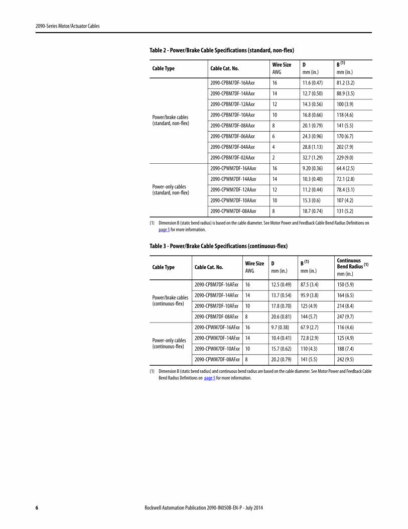
Table 2 - Power/Brake Cable Specifications (standard, non-flex)
Table 3 - Power/Brake Cable Specifications (continuous-flex)
Cable Type Cable Cat. No.Wire SizeAWG
Dmm (in.)
B (1)
mm (in.)
(1) Dimension B (static bend radius) is based on the cable diameter. See Motor Power and Feedback Cable Bend Radius Definitions on page 5 for more information.
Power/brake cables(standard, non-flex)
2090-CPBM7DF-16AAxx 16 11.6 (0.47) 81.2 (3.2)
2090-CPBM7DF-14AAxx 14 12.7 (0.50) 88.9 (3.5)
2090-CPBM7DF-12AAxx 12 14.3 (0.56) 100 (3.9)
2090-CPBM7DF-10AAxx 10 16.8 (0.66) 118 (4.6)
2090-CPBM7DF-08AAxx 8 20.1 (0.79) 141 (5.5)
2090-CPBM7DF-06AAxx 6 24.3 (0.96) 170 (6.7)
2090-CPBM7DF-04AAxx 4 28.8 (1.13) 202 (7.9)
2090-CPBM7DF-02AAxx 2 32.7 (1.29) 229 (9.0)
Power-only cables(standard, non-flex)
2090-CPWM7DF-16AAxx 16 9.20 (0.36) 64.4 (2.5)
2090-CPWM7DF-14AAxx 14 10.3 (0.40) 72.1 (2.8)
2090-CPWM7DF-12AAxx 12 11.2 (0.44) 78.4 (3.1)
2090-CPWM7DF-10AAxx 10 15.3 (0.6) 107 (4.2)
2090-CPWM7DF-08AAxx 8 18.7 (0.74) 131 (5.2)
Cable Type Cable Cat. No.Wire SizeAWG
Dmm (in.)
B (1)
mm (in.)
(1) Dimension B (static bend radius) and continuous bend radius are based on the cable diameter. See Motor Power and Feedback Cable Bend Radius Definitions on page 5 for more information.
ContinuousBend Radius (1)
mm (in.)
Power/brake cables(continuous-flex)
2090-CPBM7DF-16AFxx 16 12.5 (0.49) 87.5 (3.4) 150 (5.9)
2090-CPBM7DF-14AFxx 14 13.7 (0.54) 95.9 (3.8) 164 (6.5)
2090-CPBM7DF-10AFxx 10 17.8 (0.70) 125 (4.9) 214 (8.4)
2090-CPBM7DF-08AFxx 8 20.6 (0.81) 144 (5.7) 247 (9.7)
Power-only cables(continuous-flex)
2090-CPWM7DF-16AFxx 16 9.7 (0.38) 67.9 (2.7) 116 (4.6)
2090-CPWM7DF-14AFxx 14 10.4 (0.41) 72.8 (2.9) 125 (4.9)
2090-CPWM7DF-10AFxx 10 15.7 (0.62) 110 (4.3) 188 (7.4)
2090-CPWM7DF-08AFxx 8 20.2 (0.79) 141 (5.5) 242 (9.5)
6 Rockwell Automation Publication 2090-IN050B-EN-P - July 2014

2090-Series Motor/Actuator Cables
Table 4 - Power/Brake Cable Pinouts (10, 8, 6, 4, and 2 AWG)
Power/Brake Cable Type Cable Cat. No. Description
Power/brake cables(standard, non-flex)
2090-CPBM7DF-10AAxx, 2090-CPBM7DF-08AAxx, 2090-CPBM7DF-06AAxx
Power/brake cables(continuous-flex)
2090-CPBM7DF-10AFxx, 2090-CPBM7DF-08AFxx
Power-only cables(standard, non-flex)
2090-CPWM7DF-10AAxx, 2090-CPWM7DF-08AAxx
Power-only cables(continuous-flex)
2090-CPWM7DF-10AFxx, 2090-CPWM7DF-08AFxx
Power/brake cables(standard, non-flex)
2090-CPBM7DF-04AAxx, 2090-CPBM7DF-02AAxx
UVWPE
MBRK+MBRK–
UVW
+–
W21
+ –
V
U
Twisted Wire Pair360° shield-to-ground connections required.
To Motor
ConnectorBackshell
Shielded 360°Shield Wire Connection
To Drive
18 AWG White18 AWG Black
Shield
BrownBlackBlue
Green/Yellow
UVW
UVWPE
W21
+ –V
U
360° shield-to-ground connections required.
To Motor
ConnectorBackshell
Shielded 360°
Shield
Wire Connection
To Drive
BrownBlackBlue
Green/Yellow
Shield
UVW
+–
UVW
MBRK+MBRK–
V –
12
U
+
W
360° shield-to-ground connections required.
To Motor
ConnectorBackshell
Shielded 360°Shield Wire Connection
To Drive
Twisted Wire Pair
Brown
BlueGreen/Yellow
WhiteBlack
Shield
Black
Rockwell Automation Publication 2090-IN050B-EN-P - July 2014 7

2090-Series Motor/Actuator Cables
Table 5 - Power/Brake Cable Pinouts (16, 14, and 12 AWG)
Power/Brake Cable Type Cable Cat. No. Description
Power/brake cables (standard, non-flex)
2090-CPBM7DF-16AAxx, 2090-CPBM7DF-14AAxx, 2090-CPBM7DF-12AAxx
Power/brake cables (continuous-flex)
2090-CPBM7DF-16AFxx, 2090-CPBM7DF-14AFxx
Power-only cables(standard, non-flex)
2090-CPWM7DF-16AAxx, 2090-CPWM7DF-14AAxx, 2090-CPWM7DF-12AAxx
Power-only cables(continuous-flex)
2090-CPWM7DF-16AFxx, 2090-CPWM7DF-14AFxx
ABCD
FG
C B
A
EF
G
HL
D
UVWPE
MBRK+MBRK-
Twisted Wire Pair360° shield-to-ground connections required.
To Motor
Connector Backshell Shielded 360°
Shield
Wire Connection
To Drive
BrownBlackBlue
Green/Yellow
18 AWG White18 AWG Black
Shield
ABCD
C B
A
EF
G
HL
D
UVWPE
360° shield-to-ground connection required.
To Motor
Shield Wire Connection
To Drive
Connector Backshell Shielded 360°
Brown
BlueGreen/Yellow
Shield
Black
8 Rockwell Automation Publication 2090-IN050B-EN-P - July 2014
2090-Series Motor/Actuator Cables
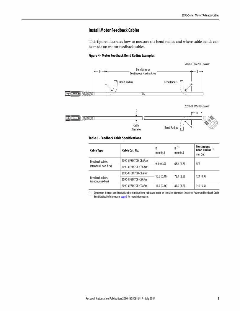
Install Motor Feedback Cables
This figure illustrates how to measure the bend radius and where cable bends can be made on motor feedback cables.
Figure 4 - Motor Feedback Bend Radius Examples
Table 6 - Feedback Cable Specifications
2090-CFBM7DD-xxxxxx
B B
BD
Bend Area orContinuous Flexing Area
Bend RadiusBend Radius
CableDiameter Bend Radius
2090-CFBM7DF-xxxxxx
Cable Type Cable Cat. No.Dmm (in.)
B (1)
mm (in.)
(1) Dimension B (static bend radius) and continuous bend radius are based on the cable diameter. See Motor Power and Feedback Cable Bend Radius Definitions on page 5 for more information.
ContinuousBend Radius (1)
mm (in.)
Feedback cables(standard, non-flex)
2090-CFBM7DD-CEAAxx9.8 (0.39) 68.6 (2.7) N/A
2090-CFBM7DF-CEAAxx
Feedback cables (continuous-flex)
2090-CFBM7DD-CEAFxx10.3 (0.40) 72.1 (2.8) 124 (4.9)
2090-CFBM7DF-CEAFxx
2090-CFBM7DF-CDAFxx 11.7 (0.46) 81.9 (3.2) 140 (5.5)
Rockwell Automation Publication 2090-IN050B-EN-P - July 2014 9

2090-Series Motor/Actuator Cables
2090-CFBM7DD-CEAAxx feedback cables (-CE designation) have fewer conductors and are designed for motors with high-resolution absolute-position encoders.
Table 7 - Feedback Cable Pinouts (premolded cable connectors)
Feedback Cable Type Cable Cat. No. Description
Feedback cable(standard, non-flex) 2090-CFBM7DD-CEAAxx
Feedback cable(continuous-flex) 2090-CFBM7DD-CEAFxx
12345
101467
11
1234569
1011131412
SIN+/AM+SIN-/AM-COS+/BM+COS-/BM-DATA+/IM+/R1DATA-/IM-/R2EPWR 5VECOM EPWR 9VTS+TS-ECOM
SIN+/AM+SIN-/AM-
COS+/BM+COS-/BM-
DATA+/IM+/R1DATA-/IM-/R2
EPWR 5VECOM
EPWR 9VTS+
12
3
4
5
16
1514
1312
1110
9
8
76
17 1
510
15
116
22 AWG Black22 AWG White/Black22 AWG Red22 AWG White/Red22 AWG Green22 AWG White/Green22 AWG Gray
22 AWG White/Gray22 AWG Orange22 AWG White/Orange
36 AWG Shield
Motor Plug Drive Plug
Twisted Wire PairConnector Backshell Shielded 360°
Wire ConnectionShield Connector Backshell Shielded 360°
10 Rockwell Automation Publication 2090-IN050B-EN-P - July 2014

2090-Series Motor/Actuator Cables
Table 8 - Feedback Cable Pinouts (flying leads)
Feedback Cable Type Cable Cat. No. Description
Feedback cable(standard, non-flex) 2090-CFBM7DF-CEAAxx
Feedback cable(continuous-flex) 2090-CFBM7DF-CEAFxx
1234569
1011131412
SIN+/AM+SIN-/AM-COS+/BM+COS-/BM-DATA+/IM+/R1DATA-/IM-/R2EPWR 5VECOM EPWR 9VTS+TS-ECOM
12
3
4
5
16
1514
1312
1110
9
876
17
Motor Plug
22 AWG Black22 AWG White/Black22 AWG Red22 AWG White/Red22 AWG Green22 AWG White/Green22 AWG Gray22 AWG White/Gray22 AWG Orange22 AWG White/Orange
36 AWG Shield
To Drive
Twisted Wire PairConnector Backshell Shielded 360°
Wire ConnectionShield Connect Cable Shield to Ground
Rockwell Automation Publication 2090-IN050B-EN-P - July 2014 11

2090-Series Motor/Actuator Cables
2090-CFBM7DF-CDAFxx feedback cables (-CD designation) include Hall signal conductors and are designed for motors with incremental encoders.
Table 9 - Feedback Cable Pinouts (flying-leads with Hall signals)
Install Continuous-flex Extension Cables
This figure illustrates how to measure the bend radius and where cable bends can be made on continuous-flex extension cables.
Figure 5 - Continuous-flex Extension Cable Bend Radius Example
Feedback Cable Type Cable Cat. No. Description
Feedback cable(continuous-flex) 2090-CFBM7DF-CDAFxx
N/C N/C
1234569
1011131415161778
12
SIN+/AM+SIN-/AM-COS+/BM+COS-/BM-DATA+/IM+DATA-/IM-EPWR 5VECOM EPWR 9VTS+TS-S1 S2 S3 Spare ABSECOM
N/C
12
3
4
5
16
1514
1312
1110
9
8
76
17
Twisted Wire Pair
Motor Plug
Connector Backshell Shielded 360°Wire Connection
To Drive
Shield Connect Cable Shield to Ground
26 AWG Black26 AWG White/Black26 AWG Red26 AWG White/Red26 AWG Green26 AWG White/Green16 AWG Gray16 AWG White/Gray22 AWG Orange22 AWG White/Orange26 AWG Blue26 AWG White/Blue26 AWG Yellow26 AWG White/Yellow26 AWG Brown26 AWG White/Brown
36 AWG Shield
B
BD
Bend Area or Continuous Flexing Area 2090-CPBM7E7-xxAFxx cable is shown.Continuous
Bend Radius CableDiameter
12 Rockwell Automation Publication 2090-IN050B-EN-P - July 2014

2090-Series Motor/Actuator Cables
Extension Power Cable Pinout Diagrams and Specifications
Table 10 - Extension Power/Brake Cable Pinouts
Table 11 - Extension Power/Brake Cable Specifications
Extension Cable Type Cable Cat. No. Description
Extension power/brake cable(continuous-flex)
2090-CPBM7E7-16AFxx, 2090-CPBM7E7-14AFxx, 2090-CPBM7E7-10AFxx, 2090-CPBM7E7-08AFxx
C B
A
E
F
H L
CB
AF
U
VW
U
V
W
A
BC
A
B
C
F
G
E
H
L
F
G
E
H
L
MBRK+
MBRK-
MBRK+
MBRK-+
–
1
2
+
–
1
2
VV–
–WW
22 11
UU
++
G G
L EH
2090-CPBM7E7-16AFxx 2090-CPBM7E7-14AFxx
2090-CPBM7E7-10AFxx 2090-CPBM7E7-08AFxx
Brown
Black
Blue
Green/Yellow
18 AWG White
18 AWG Black
Shield
Motor Plug Extension Plug
Twisted Wire PairConnector Backshell Shielded 360°
Wire ConnectionShield Connect Cable Shield to Ground
Cable Type Cable Cat. No.Wire SizeAWG
Dmm (in.)
B (1)
mm (in.)
ContinuousBend Radius (1)
mm (in.)
Extension power/brake cables (continuous-flex)
2090-CPBM7E7-16AFxx 16 12.5 (0.49) 87.5 (3.4) 150 (5.9)
2090-CPBM7E7-14AFxx 14 13.7 (0.54) 95.9 (3.8) 164 (6.4)
2090-CPBM7E7-10AFxx 10 17.8 (0.70) 125 (4.9) 214 (8.4)
2090-CPBM7E7-08AFxx 8 20.6 (0.81) 144 (5.7) 247 (9.7)
(1) Dimension B (static bend radius) and continuous bend radius are based on the cable diameter. See Motor Power and Feedback Cable Bend Radius Definitions on page 5 for more information.
Rockwell Automation Publication 2090-IN050B-EN-P - July 2014 13

2090-Series Motor/Actuator Cables
Extension Feedback Cable Pinout Diagrams and Specifications
2090-CFBM7E7-CEAFxx feedback cables (-CE designation) have fewer conductors and are designed for motors with high-resolution absolute-position encoders.
2090-CFBM7E7-CDAFxx feedback cables (-CD designation) include Hall signal conductors and are designed for motors with incremental encoders.
Table 12 - Extension Feedback Cable Pinouts
Table 13 - Extension Feedback Cable Specifications
Cable Type Cable Cat. No. Description
Extension feedback cable (continuous-flex)
2090-CFBM7E7-CEAFxx,2090-CFBM7E7-CDAFxx 1
234569
101113
15*16*17*
1234569
10111314
15*16*17*12
SIN+/AM+SIN-/AM-COS+/BM+COS-/BM-DATA+/IM+/R1DATA-/IM-/R2EPWR 5VECOM EPWR 9VTS+TS-S1 S2 S3 ECOM
SIN+/AM+SIN-/AM-
COS+/BM+COS-/BM-
DATA+/IM+DATA-/IM-
EPWR 5VECOM
EPWR 9VTS+
S1 S2 S3
12
3
4
5
16
1514
1312
1110
9
8
76
17
12
3
4
5
16
15
14
13
12
11
10
9
87 6
17
N/C N/C
N/C
26 AWG Black26 AWG White/Black26 AWG Red26 AWG White/Red26 AWG Green26 AWG White/Green16 AWG Gray16 AWG White/Gray22 AWG Orange22 AWG White/Orange
36 AWG Shield
Motor Plug Extension Plug
Twisted Wire PairConnector Backshell Shielded 360°
Wire ConnectionShield Connector Backshell Shielded 360°
26 AWG Blue26 AWG White/Blue26 AWG Yellow26 AWG White/Yellow
Cable Type Cable Cat. No.Dmm (in.)
B (1)
mm (in.)
(1) Dimension B (static bend radius) and continuous bend radius are based on the cable diameter. See Motor Power and Feedback Cable Bend Radius Definitions on page 5 for more information.
ContinuousBend Radius (1)
mm (in.)
Extension feedback cables (continuous-flex)
2090-CFBM7E7-CEAFxx 10.3 (0.40) 72.1 (2.8) 124 (4.9)
2090-CFBM7E7-CDAFxx (2)
(2) Pins 15, 16, and 17 (marked with an asterisk) for Hall signals S1, S2, and S3, apply to only this feedback cable. The other feedback cable (with the -CE designation) does not include these conductors.
11.7 (0.46) 81.9 (3.2) 140 (5.5)
14 Rockwell Automation Publication 2090-IN050B-EN-P - July 2014

2090-Series Motor/Actuator Cables
Install the Right Angle Cables Follow these steps to attach a right-angle cable connector to the motor connector.
1. Align all flat surfaces on the cable connector with the flat surface on the motor connector.
2. Push the cable connector onto the motor connector to fully seat the connection.
3. Twist the knurled front end of the cable connector clockwise approximately 60° to secure the connection.
Right-angle Power/Brake Cables
This figure illustrates how to measure the bend radius and where cable bends can be made on right-angle power/brake cables.
Figure 6 - Right-angle Power/Brake Cable Bend Radius Example
Table 14 - Right-angle Power/Brake Cable Specifications
You can reposition right-angle power cables in 90° increments. Follow these steps to reposition the power cable connector.
1. Remove the four 2 mm hex screws on the back of the cable connector.
2. Reposition the connector body to a new position by rotating the connector 90°, 180°, or 270°.
3. Secure the two parts together with the four 2 mm hex screws.
Torque screws to 0.25 N•m (2.2 lb•in), maximum.
71.0(2.8)
82.0(3.2)
150(5.9)
11.6(0.46)
81.2(3.2)
81.2(3.2) Bend Area
CableDiameterHex Screw (4x)
Cable Shields
Power/Brake Cable Type Cable Cat. No.Wire SizeAWG
Available Lengthsmm (in.)
Connector IP Rating
Right-angle power/brake cable (standard, non-flex) 2090-CPBM7DF-16RAxx
16 (power)18 (brake)
3, 6, 9, 15 m(10, 16, 30, 49 ft)
IP54(dust protected, splashing water)
Rockwell Automation Publication 2090-IN050B-EN-P - July 2014 15

2090-Series Motor/Actuator Cables
Table 15 - Right-angle Power/Brake Cable Pinouts
Right-angle Feedback Cables
This figure illustrates how to measure the bend radius and where cable bends can be made on right-angle feedback cables.
Figure 7 - Right-angle Power/Brake Cable Bend Radius Example
Table 16 - Right-angle Feedback Cable Specifications
Power/Brake Cable Type Cable Cat. No. Description
Right-angle power/brake cable (standard, non-flex) 2090-CPBM7DF-16RAxx
A
BC
D
EF
G
HL
ABC
FGEHL
UVW
MBRK+MBRK-
Wire Connection Twisted Wire Pair
Hex Screw (4x)
BrownBlackBlue
Green/YellowWhiteBlack
Shield
61.0(2.4)
81.0(3.2)
9.8(0.38)
68.6(2.7)
68.6(2.7)
Bend Area
CableDiameterRotation Point
Feedback Cable Type Cable Cat. No.Wire SizeAWG
Available Lengthsmm (in.)
Connector IP Rating
Right-angle feedback cable (standard, non-flex) 2090-CFBM7DF-CERAxx 22 3, 6, 9, 15 m
(10, 16, 30, 49 ft)IP67(dust tight, water immersion)
16 Rockwell Automation Publication 2090-IN050B-EN-P - July 2014

2090-Series Motor/Actuator Cables
The right-angle feedback cable can be rotated 124° to the left of center or 200° to the right of center. Follow these steps to rotate the feedback cable connector.
1. Mount the cable on the motor connector.
2. Use two hands to rotate the connector into position.a. Grasp the front and rear sections of the connector.b. Use one hand to stabilize the front section of the connector (the area
with the knurled locking sleeve) and the connector on the motor.c. Use your other hand to rotate the back section of the connector (the
area with the cable) into position.
Table 17 - Right-angle Feedback Cable Pinout
Feedback Cable Type Cable Cat. No. Description
Right-angle feedback cable (standard, non-flex) 2090-CFBM7DF-CERAxx
910
1112
13
14 15
16
17
2
34 5 6 7 8
1
12
34
56
910
1113
14
12
Rotation Point
Wire Connection Twisted Wire Pair
BlackWhite/Black
RedWhite/Red
GreenWhite/Green
GrayWhite/Gray
OrangeWhite/Orange
Drain
SIN+/AM+SIN-/AM-
COS+/BM+COS-/BM-
DATA+/IM+/R1DATA-/IM-/R2
EPWR 9V DCCOM
EPWR 5V DCTS+
TS-
COM
Rockwell Automation Publication 2090-IN050B-EN-P - July 2014 17

2090-Series Motor/Actuator Cables
Additional Resources These documents contain additional information concerning related products from Rockwell Automation.
You can view or download publications at http://www.rockwellautomation.com/literature/. To order paper copies of technical documentation, contact your local Allen-Bradley distributor or Rockwell Automation sales representative.
Resource Description
Kinetix Motion Control Selection Guide,publication GMC-SG001
Overview of Kinetix servo drives, motors, actuators, and motion accessories that are designed to help make initial decisions for the motion control products that are best suited for your system requirements.
Kinetix Rotary Motion Specifications,publication GMC-TD001
Product specifications for Kinetix VP (Bulletin VPL, VPF, VPS), MP-Series™ (Bulletin MPL, MPM, MPF, MPS), Kinetix 6000M (Bulletin MDF), TL-Series™, RDD-Series™, and HPK-Series™ rotary motors.
Kinetix Linear Motion Specifications,publication GMC-TD002
Product specifications for Bulletin MPAS and MPMA linear stages, Bulletin MPAR, MPAI, and TLAR electric cylinders, and LDC-Series and LDL-Series linear motors.
Kinetix Servo Drives Specifications,publication GMC-TD003
Product specifications for Kinetix Integrated Motion over the EtherNet/IP network, Integrated Motion over sercos interface, EtherNet/IP networking, and component servo drive families.
Kinetix Motion Accessories Specifications,publication GMC-TD004
Product specifications for Bulletin 2090 motor and interface cables, low-profile connector kits, drive power components, and other servo drive accessory items.
Kinetix 5500 Servo Drives User Manual,publication 2198-UM001
Provides information on installing, configuring, startup, troubleshooting, and applications for your Kinetix servo drive system.
Kinetix 6200 and Kinetix 6500 Modular Servo Drives User Manual, publication 2094-UM002
Kinetix 6000 Multi-axis Servo Drive User Manual, publication 2094-UM001
Kinetix 300 EtherNet/IP Indexing Servo Drives User Manual, publication 2097-UM001
Kinetix 350 Single-axis EtherNet/IP Servo Drives User Manual, publication 2097-UM002
Kinetix 3 Component Servo Drives User Manual, publication 2071-UM001
System Design for Control of Electrical Noise Reference Manual, publication GMC-RM001
Provides information, examples, and techniques that are designed to minimize system failures that are caused by electrical noise.
Product Certifications website, http://www.ab.com Provides declarations of conformity, certificates, and other certification details.
18 Rockwell Automation Publication 2090-IN050B-EN-P - July 2014

2090-Series Motor/Actuator Cables
Notes:
Rockwell Automation Publication 2090-IN050B-EN-P - July 2014 19

Rockwell Automation Support
Rockwell Automation provides technical information on the Web to assist you in using its products.At http://www.rockwellautomation.com/support you can find technical and application notes, sample code, and links to software service packs. You can also visit our Support Center at https://rockwellautomation.custhelp.com/ for software updates, support chats and forums, technical information, FAQs, and to sign up for product notification updates.
In addition, we offer multiple support programs for installation, configuration, and troubleshooting. For more information, contact your local distributor or Rockwell Automation representative, or visit http://www.rockwellautomation.com/services/online-phone.
Installation Assistance
If you experience a problem within the first 24 hours of installation, review the information that is contained in this manual. You can contact Customer Support for initial help in getting your product up and running.
New Product Satisfaction Return
Rockwell Automation tests all of its products to help ensure that they are fully operational when shipped from the manufacturing facility. However, if your product is not functioning and needs to be returned, follow these procedures.
Documentation Feedback
Your comments will help us serve your documentation needs better. If you have any suggestions on how to improve this document, complete this form, publication RA-DU002, available at http://www.rockwellautomation.com/literature/.
United States or Canada 1.440.646.3434
Outside United States or Canada Use the Worldwide Locator at http://www.rockwellautomation.com/rockwellautomation/support/overview.page, or contact your local Rockwell Automation representative.
United States Contact your distributor. You must provide a Customer Support case number (call the phone number above to obtain one) to your distributor to complete the return process.
Outside United States Please contact your local Rockwell Automation representative for the return procedure.
Allen-Bradley, HPK-Series, Kinetix, MP-Series, RDD-Series, Rockwell Software, Rockwell Automation, and TL-Series are trademarks of Rockwell Automation, Inc.
Trademarks not belonging to Rockwell Automation are property of their respective companies.
Rockwell Otomasyon Ticaret A.Ş., Kar Plaza İş Merkezi E Blok Kat:6 34752 İçerenköy, İstanbul, Tel: +90 (216) 5698400
Rockwell Automation maintains current product environmental information on its website at http://www.rockwellautomation.com/rockwellautomation/about-us/sustainability-ethics/product-environmental-compliance.page.
Publication 2090-IN050B-EN-P - July 2014Supersedes Publication 2090-IN050A-EN-P - April 2014 Copyright © 2014 Rockwell Automation, Inc. All rights reserved. Printed in the U.S.A.