20f3 - reliable jet maintenance trackerrjmtracker.com/files/avionics-installation-part-2.pdf ·...
TRANSCRIPT
•
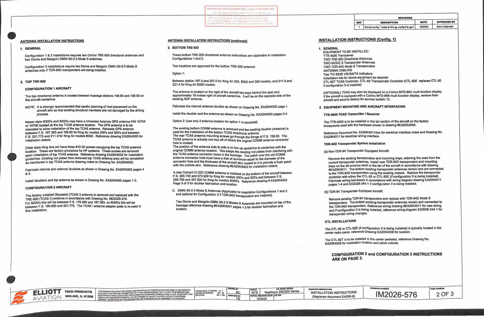
ANTENNA INSTALLATION INSTRUCTIONS
1. GENERAL
Configuration 1 & 2 installations requires two Collins TRE-920 directional antennas and two Dome and Margolin DMNI-50-2-2 Mode S antennas.
Configuration 3 installations require two Dome and Margolin DMNI-50-2-2 Mode S antennas only if TDR-94D transponders are being installed.
2. TOP TRE-920
CONFIGURATION 1 AIRCRAFT
The top directional antenna is located between fuselage stations 148.90 and 158.00 on the aircraft center1ine.
NOTE: It is strongly recommended that careful planning of rivet placement on the aircraft skin so that existing structural members are not damaged by the drilling process.
Newer style 8300's and B200's may have a Universal Avionics GPS antenna PIN 10704 or 10706 located at the top TCAS antenna location. The GPS antenna is to be relocated to allow installation of the top TCAS antenna. Relocate GPS antenna between F .S. 187.383 and 198.65 for King Air models 200's and 300's and between F.S. 201.ns and 211 .9 for King Air models 8300. Reference drawing EA20K4005 for installation details.
Older style King Airs will have three #10-32 screws occupying the top TCAS antenna location. These are factory provisions for HF systems. These screws are removed upon installation of top TCAS antenna. Reference drawing EA20K4002 for installation guidelines. Existing nut plates from removed top TCAS antenna area will be reinstalled as mentioned in top TCAS antenna drawing notes on Drawing No. EA20K4002.
Fabricate internal and external doublers as shown in Drawing No. EA20K4002 pages 4 &5.
Install doublers and top antenna as shown in Drawing No. EA20K4002 pages 1-3.
CONFIGURATION 2 AIRCRAFT
The factory installed Skywatch (TCAS I) antenna is removed and replaced with the TRE-920 (TCAS II) antenna in accordance with Drawing No. MD2026-576. For B200's this will be between F.S. 176.250 and 187.383, on B300's this will be between F.S. 190.650 and 201.n5. The TCAS I antenna adapter plate is re-used in this installation.
RESTRICTED USE OOCUI.:EI<T 0 1/LY VALID IF ~1ARKED RED
Th.> FAA ;..p;:,vvad STCt S•\0 • -11 •·JT. u"'l ~n
' - - - - • - • ~. -- - -- •. ' w
ST-. cc s • a• T c1:> • t , 1 ' 1 • rpos e re c J • • co.o:c:r:onA·.t.lcO 1 :.qct " L1.
ANTENNA INSTALLATION INSTRUCTIONS (continued)
3. BOTTOM TRE-920
These bottom TRE-920 directional antenna instructions are applicable to installation Configurations 1 and 2.
Two locations are approved for the bottom TRE-920 antenna:
Option 1:
Between station 197.5 and 207.0 for Klng Air 200, B200 and 300 models, and 211 .9 and 221.4 for King Air B300 models.
The antenna Is located on the right of the aircraft two bays behind the spar and approximately 19 inches right of aircraft center1ine. It will be on the opposite side of the existing ADF antenna.
Fabricate the internal antenna doubler as shown on Drawing No. EA20K4000 page 1.
Install the doubler and the antenna as shown on Drawing No. EA20K4000 pages 2-4.
Option 2: (use only if antenna location for option 1 is occupied)
The existing .bottom _GOMM antenna is removed and the existing doubler (massive) is used for the Installation of the bottom TCAS directional antenna. The rear TCAS antenna mounting screws go through the flange of F.S. 158.00. The TCA~ antenna is actually one bay aft of where the original COMM antenna connector hole 1s located. T~e. position of the antenna s~de to si~e is to line up centerline to centerline with ~e . ong1nal COMM antenna location. Th1s keeps the existing nut plates from interfenng With the TCAS antenna connector holes in the fuselage. The patch over the old COMM antenna connector hole must have a disk of aluminu qual to the diameter of the connector hole and the thickness of the aircraft skin ~ eted to it to provide a flush patch with the outside skin. Reference drawing #EA2oK~v; for installation details.
A naw Comant Cl-223 COMM antenna is installed on the bottom of the aircraft between F.S. 265.750 and 273.520 ~r Ki~g Air models 200's and 300's and between F.S. 299.750 and 307.520 for Ki~g Air models B300's. Reference drawing# EA20K4003 Page 3 of 3 for doubler fabncation and location.
C. DMNI~50-2-2 Mode S Ant_ennas (Applicable to installation Configurations 1 and 2 and optional for Configuration 3 if TDR-94D transponders are installed)
Two Dome and Margoli~ DMNI 50-2-2 Modes S Antennas are mounted on top of the fusel~ge reference draw1ng #EA20K4001 pages 1-3 for doubler fabrication and location.
REVISIONS
~ DeSCRIPTION I DATI! I APPROWD BY
1 Moved conllg 1 notee to this pg. cont'ig 2 to pg 3 I 10122K14 I Bmnl Cattanach
INSTALLATION INSTRUCTIONS (Config.1)
1. GENERAL EQUIPMENT TO BE INSTALLED: TIR-4000 Transceiver TWO TRE-920 Directional Antennas TWO MODE S Transponder Antennas TWO TDR-94D Mode S Transponders ANTENNA CABLING Two TVI-920D VSI/RAITA Indicators Installation kits for above equipment as required CTL-92T TCAS Controller, CTL-92 Transponder Controller (CTL·92E replaces CTL-92 if configuration 3 is installed)
(OPTIONAL) TCAS may also be displayed on a Collins MFD-85C multi-function display. If the aircraft is equipped with a Collins MFD-85B multi-function display, remove from aircraft and send to factory for service bulletin 13.
2. EQUIPMENT MOUNTING AND AIRCRAFT INTERFACING
TTR-4000 TCAS Transmitter I Receiver
The TTR-4000 is to be installed in the tail section of the aircraft on the factory honeycomb shelf with the hardware shown in drawing #EA20K4004.
Reference Document No. EA20K4011 doc for electrical interface notes and Drawing No. EA20K40 11 for electrical wiring interface.
TDR-940 Transponder System Installation
(a) Non-TDR-94 Transponder Equipped Aircraft
Remove the existing transponders and mounting trays, retaining the coax from the current transponder antennas. Install naw TDR-940 transponders and mounting trays on the aft avionics shelf in the tail of the aircraft in accordance with drawing #EA20K4011 . The bottom existing transponder antennas remain and are connected to the TOR-94D transponders using the existing coaxes. Replace the transponder controller with either the CTL-92 or CTL-92E (if configuration 3 is being installed). Fabricate wiring harnesses in accordance with wiring diagram drawing EA20K4011 pages 1-4 and ED2026-344-1 if configuration 3 is being installed.
(b) TDR-94 Transponder Equipped Aircraft:
Remove existing TDR-94 transponders and replace with TDR-94D Mode S transponders. The bottom existing transponder antennas remain and connect~ to the TDR-94D transpondem. Reference wiring drawing #EA20K4011 for new Wlnng and if configuration 3 is being installed, reference wiring diagram ED2026-344-1 for transponder wiring changes.
CTL INSTALLATIONS
The CTL-92 or CTL-92E (if configuration 3 is being installed) is typically located in the center radio panel, reference Drawing EA20K4009 for location.
The CTL-92T is to be installed in the center pedestal, reference Drawing No. EA20K4008 for installation location and panel cutouts.
CONFIGURATION 2 and CONFIGURATION 31NSTRUCTIONS ARE ON PAGE 3 .
DAAWIIIO .,._,.
20F3
•
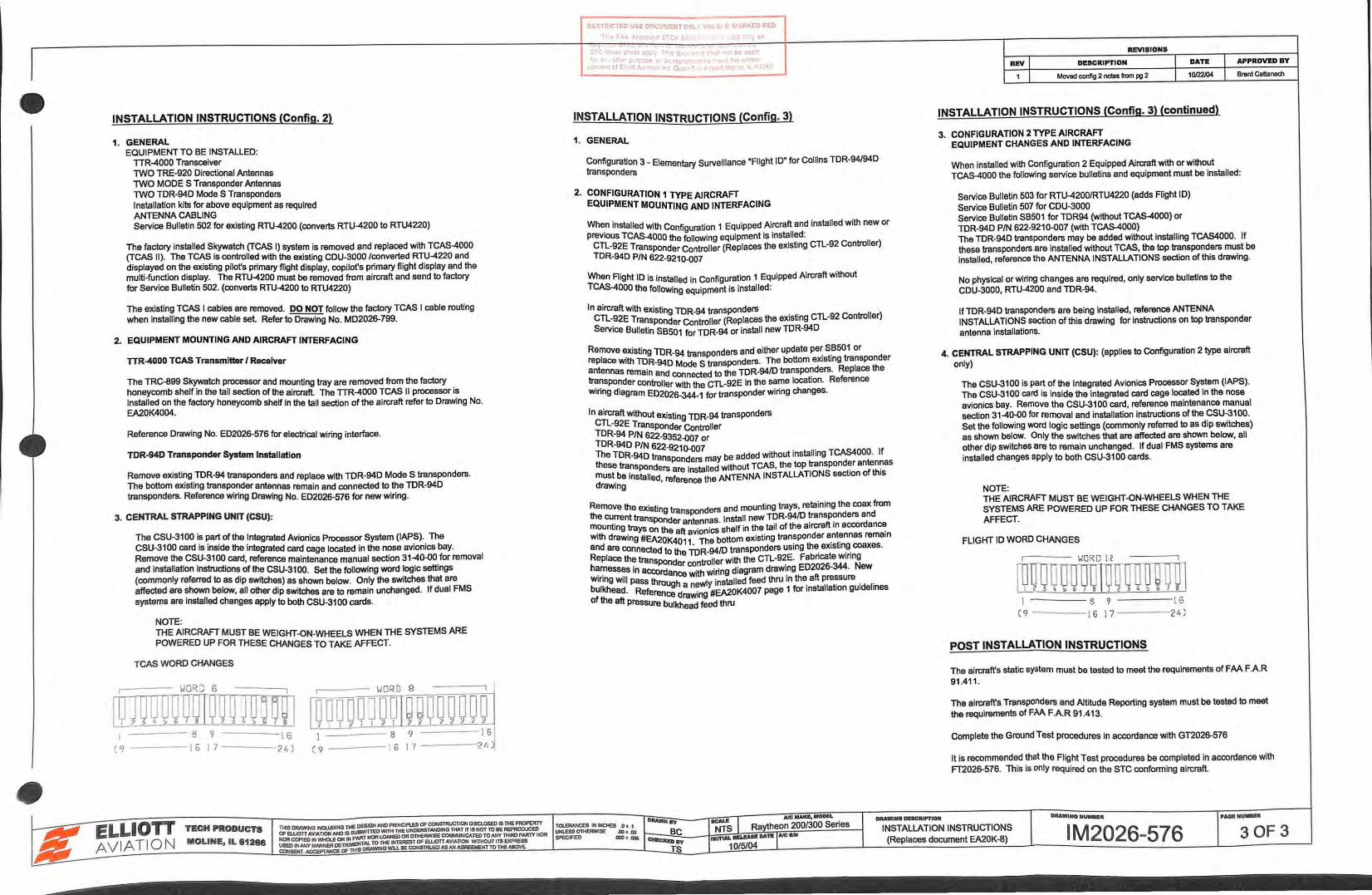
INSTALLATION INSTRUCTIONS (Config. 2)
1. GENERAL EQUIPMENT TO BE INSTALLED:
TTR-4000 Transceiver TWO TRE-920 Directional Antennas TWO MODE S Transponder Antennas TWO TDR-94D Mode S Transponders Installation kits for above equipment as required ANTENNA CABLING Service Bulletin 502 for existing RTU-4200 (converts RTU-4200 to RTU4220)
The factory installed Skywatch (TCAS I) system is removed and replaced with TCAS-4000 (TCAS II). The TCAS is controlled with the existing CDU-3000 /converted RTU-4220 and displayed on the existing pilot's primary flight display, copilot's primary flight display and the multi-function display. The RTU-4200 must be removed from aircraft and send to factory for Service Bulletin 502. (converts RTU-4200 to RTU4220)
The existing TCAS I cables are removed. DO NOT follow the factory TCAS I cable routing when Installing the new cable sel Refer to Drawing No. MD2026-799.
2.. EQUIPMENT MOUNTING AND AIRCRAFT INTERFACING
TTR-4000 TCAS Transmitter I Receiver
The TRC-899 Skywatch processor and mounting tray are removed from the factory honeycomb shelf in the tail section of the aircraft. The TTR-4000 TCAS II processor is Installed on the factory honeycomb shelf In the tall section of the aircraft refer to Drawing No. EA20K4004.
Reference Drawing No. ED2026-576 for electrical wiring interface.
TDR-94D Transponder System Installation
Remove existing TDR-94 transponders and replace with TDR-94D Mode S transponders. The bottom existing transponder antennas remain and connected to the TDR-94D transponders. Reference wiring Drawing No. ED2026-576 for new wiring.
3. CENTRAL STRAPPING UNIT (CSU):
I (9
The CSU-3100 is part of the Integrated Avionics Processor System (lAPS}. The CSU-3100 card is inside the integrated card cage located in the nose avionics bay. Remove the CSU-3100 card, reference maintenance manual section 31-40-00 for removal and installation instructions of the CSU-3100. Set the following word logic settings (commonly referred to as dip switches) as shown below. Only the switches that ara affected are shown below, all other dip switches are to remain unchanged. If dual FMS systems ara installed changes apply to both CSU-3100 cards.
NOTE: THE AIRCRAFT MUST BE WEIGHT -ON-WHEELS WHEN THE SYSTEMS ARE POWERED UP FOR THESE CHANGES TO TAKE AFFECT.
TCAS WORD CHANGES
----- 8 9 ----- 8 ---- ---1 6 17---------24) ( 9 ------; 6 I 7 -------,2 t.
RESTRICTED USE DOCUr.:EriT o;;L VAl i< ~· t.RKED RED
T • F:V. ;.J"l)fO'.-Od S'CI: ::i f. ; •c•• . c 'on . -· ~ ---' .. - " ST .. ,. . er s t a;>,. Th.., d l r : r- • be us j
to a1 • o 1 rpose "' tC' c . · ~ cor ~erE t~A;• .. =a t r·;.,~, : '' " :-IL ' . ·
INSTALLATION INSTRUCTIONS (Config. 3}
1. GENERAL
Configuration 3- Elementary Surveillance "Flight ID" for Collins TDR-94/94D transponders
2. CONFIGURATION 1 TYPE AIRCRAFT EQUIPMENT MOUNTING AND INTERFACING
When installed with Configuration 1 Equipped Aircraft and installed with new or previous TCAS-4000 the following equipment Is Installed:
CTL-92E Transponder Controller (Replaces the existing CTL-92 Controller) TDR-94D PIN 622-9210-007
When Right ID is installed in Configuration 1 Equipped Aircraft without TCAS-4000 the follOWing equipment is installed:
In aircraft with existing TDR-94 transponders CTL-92E Transponder Controller (Replaces the existing CTL-92 Controller) Service Bulletin SBso1 for TDR-94 or install new TDR-94D
Remove existing TDR-94 transponders and either update pe~ s_B501 or replace with TDR-94D Mode S transponders. The bottom eXIsting transponder antennas remain and connected to the TDR-9410 transponders. Replace the transponder controller with the CTL-g2E In the same location. Reference wiring diagram ED2026-344-1 for transponder wiring changes.
In aircraft without existing TDR-94 transponders CTL-92E Transponder Controller TDR-94 PIN 622-9352-{)07 or TDR-94D PIN 622-9210-007 The TDR-940 tra be added without installing TCAS4000. If
nsponders may tra der antennas these transponders are Installed without TCAS, the top nspon . . md ust_be installed, reference the ANTENNA INSTALLATIONS section ofth1s rawmg
Remove the existing transponders and mounting trays, retaining the coax from the current transponder antennas. Install new TDR-94/D ~nsp?nders and mounting trays on the aft . onics shelf in the tail of the a1rcraft 1n accordan~ with drawing #EA20K401 ~v'ne bottom existing transponder a_nt~nnas rama•n and are connected to the ToR-9410 transponders using the_ ex1st1n_g_ coaxes. Replace the transPDnder controller with the CTL-9~E. Fabncate w1nng h~r:nesses in aCCOrdance with wiring diagram draw1_ng ED2026-344. New w1nng will pass th h wt installed feed thru 1n the aft p~sura . _ bulkhead. Rete~ d~n/#EA20K4007 page 1 for installation gUidelines
of the aft Pressure bulkhead feed thru
llEVISIONS
uvl DESCRIPTION T DATI!
1 I Moved config 2 notes 6Qm pg 2 I 1 OI2W4
INSTALLATION INSTRUCTIONS (Config. 3) (continued}
3. CONFIGURATION 2TYPEAIRCRAFT EQUIPMENT CHANGES AND INTERFACING
I APPROWDBY
I Brenl Cattanach
When installed with Configuration 2 Equipped Aircraft with or without TCAs-4000 the following service bulletins and equipment must be installed:
service Bulletin 503 for RTU-4200/RTU4220 (adds Fflght I D) Service Bulletin 507 for CDU-3000 Service Bulletin SB501 for TDR94 (without TCAS-4000) or TDR-94D PIN 622-9210-{)07 (with TCAS-4000) The TOR-94D transponders may be added without installing TCAS4000. If these transponders are installed without TCAS, the top transponders must be installed, reference the ANTENNA INSTALLATIONS section of this drawing.
No physical or wiring changes are required, only service bulletins to the CDU-3000, RTU-4200 and TDR-94.
If TOR-940 transponders are being installed, reference ANTENNA INSTALLATIONS section of this drawing for instructions on top transponder antenna installations.
4. CENTRAL STRAPPING UNIT (CSU): (applies to Configuration 2 type aircraft only}
The CSU-3100 is part of the Integrated Avionics Processor System (lAPS). The CSU-3100 card is inside the integrated card cage locatad in the nose avionics bay. Remove the CSU-3100 card, reference maintenance manual section 31-40-00 for removal and installation instructions of the CSU-3100. Set the following word logic settings (commonly referred to as dip switches) as shown below. Only the switches that are affected are shown below, all other dip switches are to remain unchanged. If dual FMS systems ara installed changes apply to both CSU-3100 cards.
NOTE: THE AIRCRAFT MUST BE WEIGHT-ON-WHEELS WHEN THE SYSTEMS ARE POWERED UP FOR THESE CHANGES TO TAKE AFFECT.
FLIGHT ID WORD CHANGES
I 8 9 ----l 6 (9 ·----[6 17 ----24 )
POST INSTALLATION INSTRUCTIONS
The aircraft's static system must be tested to meet the requirements of FAA FAR 91 .411 .
The aircraft's Transponders and Altitude Reporting system must be tested to meet the requirements of FM FAR 91.413.
Complete the Ground Test procedures In accordance with GT2026-576
It is recommended that the Flight Test procedures be completed in accordance with FT2026-576. This is only required on the STC conforming aircraft.
•
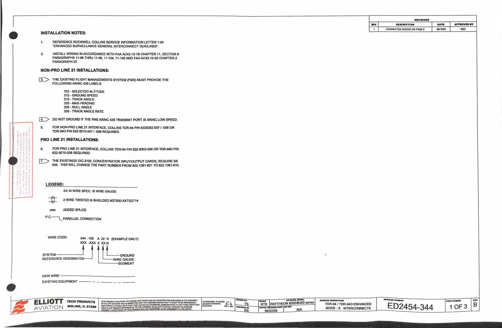
INSTALLATION NOTES:
1. REFERENCE ROCKWELL COLLINS SERVICE INFORMATION LETTER 1-<l4 "ENHANCED SURVEIUANCE GENERAL INTERCONNECT GUIDLINES".
2. INSTALL WIRING IN ACCORDANCE WITH FAA AC43.13-1 8 CHAPTER 11, SECTION 8 PARAGRAPHS 11-96 THRU 11-99, 11-104, 11-105 AND FAAAC43.13-2A CHAPTER 2 PARAGRAPH 27.
NON-PRO LINE 21 INSTALLATIONS:
lr> THE EXISTING FLIGHT MANAGEMENTS SYSTEM (FMS) MUST PROVIDE THE FOLLOWING ARINC 429 LABELS:
102- SELECTED ALTITUDE 31 2 - GROUND SPEED 313 - TRACK ANGLE 320 - MAG HEADING 325 - ROLL ANGLE 335- TRACK ANGLE RATE
[L> DO NOT GROUND IF THE FMS ARINC 429 TRANSMIT PORT IS ARINC LOW SPEED.
5. FOR NON-PRO UNE 21 INTERFACE, COLLINS TDR-94 PIN 6229352-007 /-008 OR TDR-94D PIN 622-921~7 /-008 REQUIRED.
PRO LINE 21 INSTALLATIONS:
6. FOR PRO LINE 21 INTERFACE, COLLINS TDR-94 PIN 622-9352-008 OR TDR-940 PIN 622-9210-008 REQUIRED.
[!=> THE EXISTINGS IOC-3100, CONCENTRATOR INPUT/OUTPUT CARDS, REQUIRE SB 505. THIS WILL CHANGE THE PART NUMBER FROM 822-1361-601 TO 822-1361-610.
LEGEND:
XX IN WIRE SPEC. IS WIRE GAUGE
=t:J= 2 WIRE TWISTED & SHIELDED M27500-XXTG2T14
~ ADDED SPLICE
P.C.~ PARELLEL CONNECTION
WIRE CODE: 344 -100 A 22 N (EXAMPLE ONLY)
SYSTEM T] XUkrLGROUND REFERENCE DESIGNATOR ~WIRE GAUGE
SEGMENT
NEW WIRE-- - --- ----- ----
EXISTING EQUIPMENT--- - - _ _ _ _ ---
ReVISIONS
REV DESCRIPTION APPROVED ft
CORRECTED WIRING ON PAGE 2 RSC
1 OF 3 8
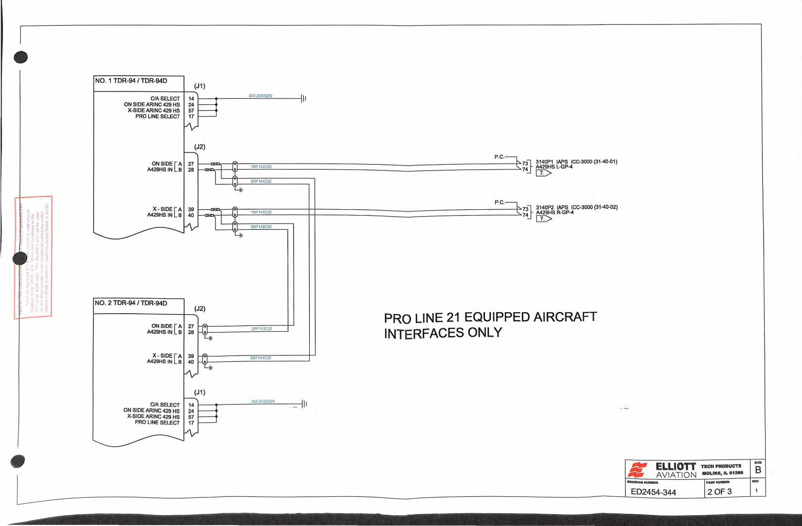
NO. 1 TOR-94/ IDR-940 (J1)
CIA SELECT 14 ON SIDE ARINC 429 HS 24 I
X-SIDE ARINC 429 HS 57 I
PRO LINE SELECT 17 1
~
(J2) 1-----
ON SIDE[ A 27 ,...,_
M29HSIN B 28 - 1-4 II X - SIDE[ A 39 r.>.
M29HSIN B 40
~ ----~ II
NO. 2 TOR-94/ IDR-940 (J2)
ON SIDE [A 27 ""' M29HSIN 8 28 ~ II
X-SIDE [A 39 __A.A
M29HSIN 8 40~ ~~~
(J1) r----..
CIA SELECT 14 ON SIDE ARINC 429 HS 24
X-51 DE ARINC 429 HS 57 PRO LINE SELECT 17
--.J~ -
•
343-200A22N :11
P.C.~
1RF142C22 .....
2RF141C22
P.C.~
1RF141C22 -~
2RF142C22
PRO LINE 21 EQUIPPE 2RF142C22
INTERFACES ONLY
2RF141C22
343203A2.2N _ _,__ 111
73l 3140P1 lAPS ICC-3000 (3140-01)
74_f M29HS L-GP-4
IT>
73l_ 3140P2 lAPS ICC-3000 (31-40-02)
74j M29HS R-GP-4
IT>
D AIRCRAFT
ELLIOTT TECH PRODUCTS
AVIATION MOLINE,IL812H
ED2454-344 2 OF3
aiD!
B
•
INSTALLATION NOTES: UNLESS OTHERWISE SPECIFIED
1.
2.
3.
5.
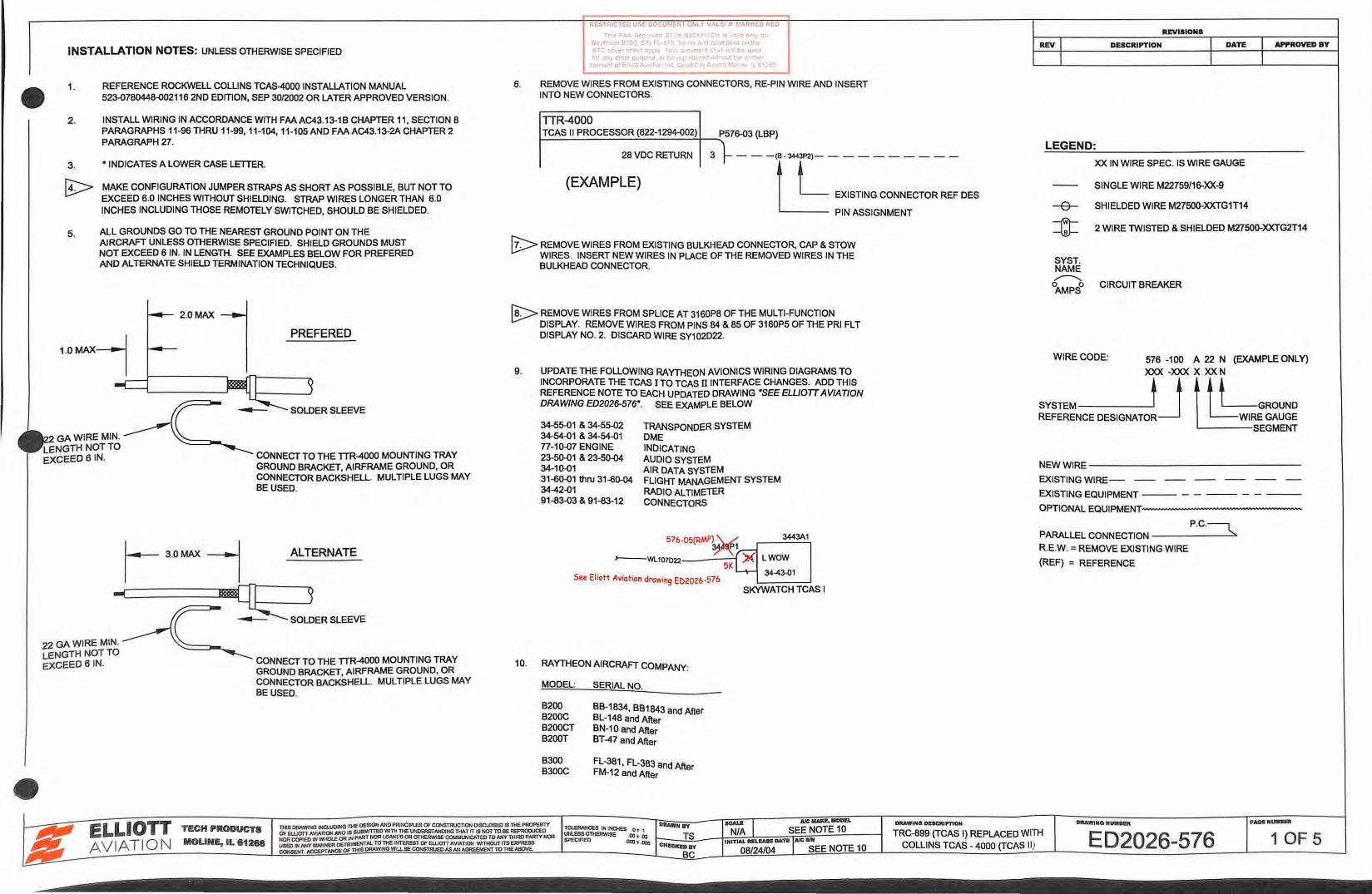
REFERENCE ROCKWELL COLLINS TCAS-4000 INSTALLATION MANUAL 523-0780448-002116 2ND EDITION, SEP 30/2002 OR LATER APPROVED VERSION.
INSTALL WIRING IN ACCORDANCE WITH FAA AC43.13-1B CHAPTER 11, SECTION 8 PARAGRAPHS 11-96 THRU 11-99,11-104, 11-105AND FAAAC43.13-2ACHAPTER2 PARAGRAPH 27.
"INDICATES A LOWER CASE LETTER.
MAKE CONFIGURATION JUMPER STRAPS AS SHORT AS POSSIBLE, BUT NOT TO EXCEED 6.0 INCHES WITHOUT SHIELDING. STRAP WIRES LONGER THAN 6.0 INCHES INCLUDING THOSE REMOTELY SWITCHED, SHOULD BE SHIELDED.
ALL GROUNDS GO TO THE NEAREST GROUND POINT ON THE AIRCRAFT UNLESS OTHERWISE SPECIFIED. SHIELD GROUNDS MUST NOT EXCEED 6 IN. IN LENGTH. SEE EXAMPLES BELOW FOR PREFERED AND ALTERNATE SHIELD TERMINATION TECHNIQUES.
2 .0MAX
1DMAX-l PRE FE RED
GAWIREMIN. NOT TO
EXCEED S IN.
22 GA WIRE MIN. LENGTH NOT TO EXCEED 6 1N.
3.0MAX
CONNECT TO THE TTR-4000 MOUNTING TRAY GROUND BRACKET, AIRFRAME GROUND, OR CONNECTOR BACKSHELL MULTIPLE LUGS MAY BE USED.
ALTERNATE
CONNECT TO THE TTR-4000 MOUNTING TRAY GROUND BRACKET, AIRFRAME GROUND, OR CONNECTOR BACKSHELL MULTIPLE LUGS MAY BE USED.
RESTRICTED USE DOCUMt.IH ONLY VI' LID IF ~~l<RKED REO
6. REMOVE WIRES FROM EXISTING CONNECTORS, RE-PJN WIRE AND INSERT INTO NEW CONNECTORS.
TIR-4000 I-T:....:C:.....A:.....S_II_P_R_O_C_E_S_S_O_R..:..(8_22_-_12_94-0 __ 02...:.)+----.:..P576-03 (LBP)
28 VDC RETURN 3 -- -(B - 3«3P2)--- -------
(EXAMPLE) t t EXISTING CONNECTOR REF CES
PIN ASSIGNMENT
[!:;::.> REMOVE WIRES FROM EXISTING BULKHEAD CONNECTOR, CAP & STOW WIRES. INSERT NEW WIRES IN PLACE OF THE REMOVED WIRES IN THE BULKHEAD CONNECTOR.
~ REMOVE WIRES FROM SPLICE AT 3160P8 OF THE MULTI-FUNCTION DISPLAY. REMOVE WIRES FROM PINS 84 & 85 OF 3160P5 OF THE PRJ FL T DISPLAY NO.2. DISCARD WIRE SY102D22.
9. UPDATE THE FOLLOWING RAYTHEON AVIONICS WIRING DIAGRAMS TO INCORPORATE THE TCAS I TO TCAS ll INTERFACE CHANGES. ADD THIS REFERENCE NOTE TO EACH UPDATED DRAWING "SEE ELUOTT AVIATION DRAWING ED2026-576". SEE EXAMPLE BELOW
34-55-01 & 34-55-02 34-54-01 & 34-54-01 n-10-07 ENGINE 23-50-01 & 23-50-04 34-10-01 31-60-01 thru 31-60-04 34-42-01 91-83-03 & 91-83-12
TRANSPONDER SYSTEM DME INDICATING AUDIO SYSTEM AIR DATA SYSTEM FLIGHT MANAGEMENT SYSTEM RADIO ALTIMETER CONNECTORS
3443A1
LWOW
See Eliott Aviation drawing ED2026-576
10. RAYTHEON AIRCRAFT COMPANY:
MODEL: SERIAL NO.
B200 B200C B200CT B200T
B300 B300C
BB-1834, BB1843 and After BL-148 and After BN-1 0 and After BT -4 7 and After
FL-381 , FL-383 and After FM-12 and After
34-43.{)1
SKYWATCH TCAS I
REVISIONS
REV DESCRIPTION
LEGEND:
XX IN WIRE SPEC. IS WIRE GAUGE
SINGLE WIRE M22759/16-XX-9
SHIELDED WIRE M27500-XXTG1T14
APPROVED BY
2 WIRE TWISTED & SHIELDED M27500-XXTG2T14
SYST. NAME ~
0AMPS
0 CIRCUIT BREAKER
WIRECODE: 576 -100 A 22 N (EXAMPLEONLY)
XXX -XXX X XX N
SYSTEM tj UkLGROUND REFERENCE DESIGNATOR l...:=WIRE GAUGE
SEGMENT
NEW WIRE--------------
EXISTING WIRE-
EXISTING EQUIPMENT--- - - -- - - --
OPTIONAL EQUIPMENT------------
P.C.~ PARALLEL CONNECTION------~
R.E.W. =REMOVE EXISTING WIRE
(REF) = REFERENCE
DIIAWINO NUIUII!R
•
RESTRICTED USE DOCUr.ldH OtiL' W l IF r,1Af<KED RED
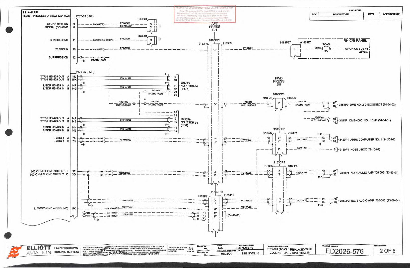
TTR-4000 REVISIONS
I-T_C_A_S_II_P_R_O_C_E_S_S_O_R-'(8_22_-1_294-{) __ 0"""'"2)T-__..,_P576-03 (L8P) APPROVED BY REV DESCRIPTION
TDC301
28 VDC RETURN SIGNAL (DC) GND
CHASSISGND
28VDC IN
SUPPRESSION
TTR-1 HS 429 OUT TTR-1 HS 429 OUT
L-TDR HS 4291N A L-TDR HS 429 IN 8
TTR-2 HS 429 OUT A TTR-2 HS 429 OUT 8
R-TDR HS 4291N A R-TDR HS 429 IN 8
L-AHC-1 A L-AHC-1 8
14A 148
14H 14J
7A 78
676-101A22 9 10
~~------------~----~~~~----------------~~11 5J6-102A22 B 12
: ~ T •. ::;:.,- -'-C ~
3455P2 N0. 1 TDR-94 ( PG 4)
L-~1~~sJ:L~G1~~-----M171113-RG316 ~ : l :7/113-RG3~ - -
25
- - - ..-(9 L--- - ---29
676-103A22
II
9 10
3455P6 NO. 2TDR-94 (PG4) I
I
I W)-- -(75 - 3443P1)- - -,FK110022 -------- - - - - --- -twh
- - (76 - 3443P1)--------------- _ __ __ _ ~
I I
FWD PRESS
BH
I 9183CP6
9183J6,...,...-'-""T"-... 9183J6 1RG1~B )--..-. _ 'l_
p.... M171113-RGm-- -+t:}-= ~~5 3454P9 DME NO. 2 DISCONNECT (34-54-02)
l ____ j)
~ _ _ 1RG~C- __ ...p. p - M17/113-RG316 D*
L 1RG104A ::'\..._ n -- M1111~RG315'i:.: ~5 3454P1 DME-4000 NO. 1 DME (34-54-01)
9163CP7
9163P7 P.C.
F* ~-- 1FK110C22-- ----{!1)-1 H.oJ- 1FK110B22 = = ---f.'lt--w--tl 78°1il._ 3420P1
w pr- - - - - --- L: : J 11t-1 u :--~ --"'-'".,-- --- - s]-o1aoP1
I I I 9163CP5
AHRS COMPUTER NO. 1 (34-20-01)
NOSE J-80X (77-1~7)
600 OHM PHONE OUTPUT HI 3F 1---4~-NIIr- - - (69 - 3443P1)- - - - - - - - - - - - - - - - - - ~ 1RZ125C22 - 1"1 11
! L _____ J. _ 9183J5
jl~l 1RZ125B22 I ----{!1)--1 H_B)-- 1RZ125A22 = = ~ ~~} 2350P1 NO. 1 AUDIO AMP 700~ (23-50-01) I i-\_B -----, - L I
I
I I I I I I I I I
I I I I I I 9183CP11 I i U-.h- --- ____ ___ ____ _ - - - -- 9183P11 U
9183J1~ _ ___ ~ _ --j'WJ ~~~==-- - - ::::-------------== B Ill V I I B}---:::: ~- B~
11
1 (2• -3443P1)- - - - - ---- - - - - - -- I U* I .-- - - - --- _j
- - - - --~ ---~ I' C:-=:J-fN't- - - (S4 - 3443P1)-1FA102G22------------ ---fN't-~ I E*
6000HM PHONEOUTPUTLO 3G - - (91 - 3443P1)- - - - --------- - - --- - a)-,
L WOW (GND = GROUND)
I .__} P.C.
I I
I I i : 1 b- 1RZ1250Zl = - =:ft= - 6
2°L 2350P2 NO. 2 AUDIO AMP 70~06 (23.50-04)
I :---\.B - -- - '-:=.7 6j" P.C.
llllAWINQ NUMIIUI
•
RESTRICTED USE DOCUr,'EIH O'ILY VALID IF ~10 RKED RED
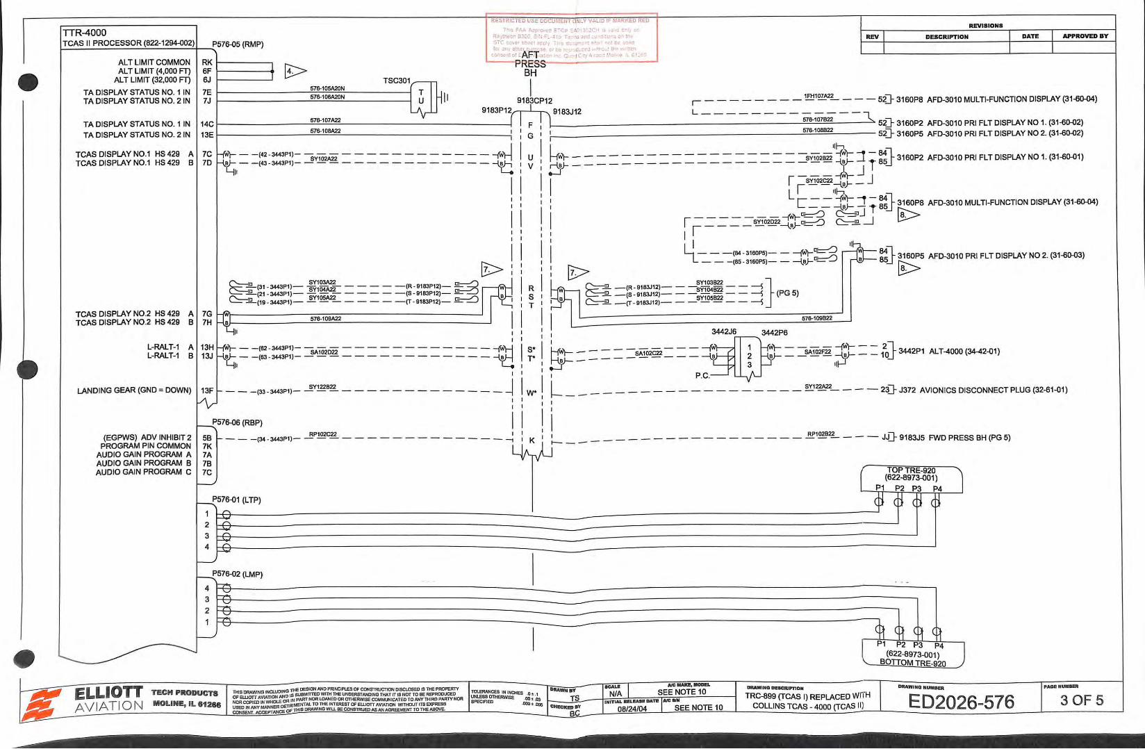
TTR-4000 REVISIONS
..) Fl..;.. f r-pro ... ~ S ... C~· .A" 3· 2 .:: J tl"l
RJJttxo.,u~OC'l:: '; F_- -1 1 T<!·nand : 0!1'
1-T_C_A_S_I_I P_R_O_C_E_S_S_O_R_,('--822_-1_2_94-0_0_2.:-.t) -....:...P571HJ5 (RMP) STCco·Jc·.-r: • ... ;:y ... hsc~~. :r. : s .. J n~·beu -· fer 'ly ct• •• r ... !,;' .. e t.! (! •• ceJ ' . th:.w ('n
c.c:"l .. : ot EA F=f :'l · ~ Cr J C ' !;.,·j)O·t ''~ ·~ Ht..L
AL T LIMIT COMMON ALT LIMIT (4,000 FT)
AL T LIMIT (32,000 FT)
TA DISPLAY STATUS NO. 1 IN TA DISPLAY STATUS NO. 2 IN
TA DISPLAY STATUS NO. 1 IN TA DISPLAY STATUS NO. 2 IN
TCAS DISPLAY N0.1 HS 429 A TCAS DISPLAY N0.1 HS 429 B
TCAS DISPLAY N0.2 HS 429 A TCAS DISPLAY N0.2 HS 429 B
L-RALT-1 A L-RALT-1 B
LANDING GEAR (GND = DOWN)
(EGPWS) ADV INHIBIT 2 PROGRAM PIN COMMON
AUDIO GAIN PROGRAM A AUDIO GAIN PROGRAM B AUDIO GAIN PROGRAM C
RK 1---------.1 SF 1-------41 6J
PRES.:> BH
TSC301~ I 7E f----------='S7~s-::..1:.::o::.5A20=N:...._ ____ ~ Tu Hll A22 7J fi76-106A20N 918fCP12 r - - - - - - - - ~1~ - - - - sD- 3160P8 AFD-3010 MULTI-FUNCTION DISPLAY (31-oo-o4)
14c l----------=fi7::.:.=..s-.:.:1o::..:7A22.=.. _______ Ltv-_______ 9_18
_3_P-1
12( I F II_9183
J12
L-------- -;;-s.;o;s;;--- "'\.. s2]- 3160P2 AFD-3010 PRI FLT DISPLAY No 1. (31-6()..{)2)
13E 1----------=07::.:.=..6-.:.:10::::BA22.=.. _______________ ~: : G I 076-108822 5:[}- 3160P5 AFD-3010 PRI FLT DISPLAY NO 2. (31-6()..{)2)
7C hWr---(42-3443P1)---------------- . . I I u i . -------- -~~~~ -Ml 7D kt;;
1
__ ,43 _3443p1, _ __§Y102A22 ____________ =ra : v 5J= = = = = = = = = = = = = _______ s~~.!: J T ss_f 3160P2 AFD-3010 PRI FLT DISPLAY NO 1. (31-6(}..{)1)
I I I ~-SY102C22-{_a}- _ j Lr llh
: : : L ~ ~ -=tJ= '"'1 t ~} 3160P8 AFD-3010 MULTI-FUNCTION DISPLAY (31-oo-o4)
II I r ~~~~-SY102022-tJ=:gg ~J_j ~ I I I I I I I I I I I I ~~-- -(84 - 3160PS)-- --jW)-~
~ L - - -(65 - 3160P5)- - -{_a}-~ t>-:: : [?> C=-:? (31 - 3443P1)- ~~= -----(R· 9183P12)-~ .A.l.. I I R l-= ~ -(R· 9183J12)- - -~~~~~- - ---s} ~2_(21- 3443P1)- SY
105A22----- -(S-9183P12)-~ ,l~.O. S ~ ~ -(S - 9183J12)-- -
5y
105822-- ---s (PG5)
C::::::-...2...(19 -3443P1)-------- -(T-9183P12)- £::--::0 I ~ T ~ -(T- 9183J12)------- ---s 7G ~ I 7H Q;.e 576-109A22 I
I LJII I I 3442J6 3442P6 I I ~
13H Hwt-- -(62 -3443P1)---------------- --tfl S* l-M- L .>. 1 -M- - ....,wr--- 2l I3J ~,-_103_,..3,1_ -""'""' ____________ 1:::! l' ty- = = = = sM== = = -s ~ ~ = ""'""" '~ __ 10_s3442P1 ALT-4000(34-42.01)
~ ~} 3160P5 AFD-3010 PRI FLT DISPLAY NO 2. (31-6()..{)3)
~
576-109822
I I P.C. '-+ 13F 1--- -(33- 3443P1)- ~y1228~------------- ~ W* l-____ -------------- ~22A22--- -23}-J372 AVIONICSDISCONNECTPLUG(32-61-01)
~ : ~571HJ6 (RBP) I
K RP102C22 I 58 1--- - (34-3443P1)----------------- -1
7K 7A 78 7C
f.--..-'
I I
I 1 RP102B22 __ JJiL 9 t- _____ - - - - - - - - - - - - - - - - - - u- 183J5 FWD PRESS BH (PG 5)
TOPTRE-920 (622-8973-001)
P1 P2 P3 P4
l P1 P2 P3 P4 (622-8973-001)
BOTIOM TRE-920
DIIAWI NQ NUIINR
j PAOII NUIIUR
•
RESTRICTED USE DOCUI.~EIIT OIILY VAI..IO I~ M.>R~-~0 ReD
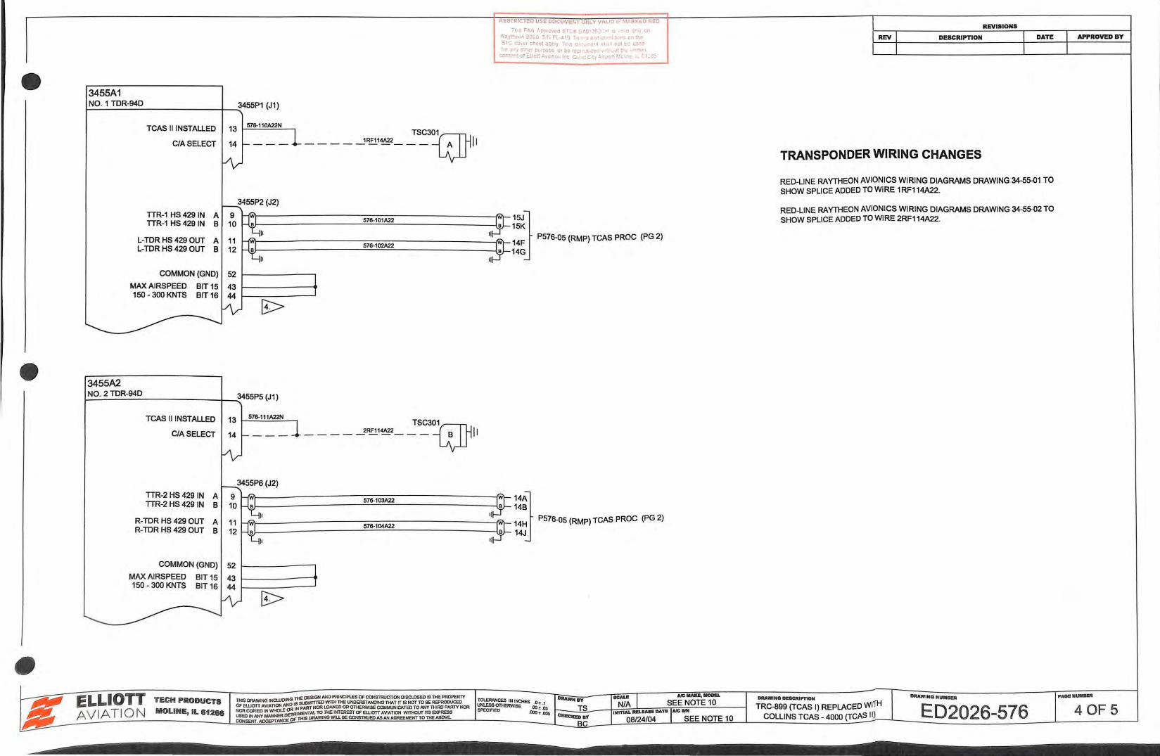
3455A1 ~N_:0:__. _1....:.T.:::..D_:R-....:.94_:D ______ ___....~3455P1 (J1)
3455A2
TCAS II INSTALLED 13 !i7S-110A22N
CIA SELECT TSC301
____ ---1~ ... , _ __ a~~
TTR-1 HS 429 IN TTR-1 HS 429 IN
L-TDR HS 429 OUT L-TDR HS 429 OUT
t--l'ill't----------::::-::::-::::--------__:_I'WI-1
1
5
4KF P576-05 (RMP) TCAS PROC (PG 2)
57S-101A22 15JJ 57S-102A22
COMMON (GND) 52 1---------.
MAX AIRSPEED BIT 15 43 1-------... 150-300 KNTS BIT 16 44 1---------'
14G
,_:.N_:0::...:.._2_TD_;__R_:-94_D ______ -+~3455P5 (J1)
TCAS II INSTALLED
CIA SELECT
13 f-=5::..:7S-:;.1:..:.1.:.::1KZ21-I==---. TSC301 ____ ___?RF114A22 ___ cy~~
TTR-2 HS 429 IN A TTR-2 HS 429 IN B
R-TOR HS 429 OUT A R-TDR HS 429 OUT B
~VI-----------::::-::::~~A22=-=---------~Q\_ :: l P576-0S (RMP) TCAS PROC (PG 2) 14Jj COMMON (GND) 52 f------.
MAX AIRSPEED BIT 15 43 150 - 300 KNTS BIT 16 44
REVISIONS
REV DESCRIPTION
TRANSPONDER WIRING CHANGES
RED-LINE RAYTHEON AVIONICS WIRING DIAGRAMS DRAWING 34-55-{)1 TO SHOW SPLICE ADDED TO WIRE 1RF114A22.
RED-LINE RAYTHEON AVIONICS WIRING DIAGRAMS DRAWING 34-55-{)2 TO SHOW SPLICE ADDED TO WIRE 2RF114A22.
APPROVED BY
RLSTRICT~D Ul>c DOCU'•l~rlT otlLY VALlO If' M'<tlK~[) I< ED
FWD T Ft.~ : CT • S<\o') "H • c J
PRESS R 's - FL ~ . 1'11'1 0 :
BH s-\ c~:. . : c ·.: :1
REVISIONS
REV I I DATE APPROVED BY DESCRIPTION
3447A1 I HONEYWELL MK VIII COMPUTER
3447P1 9183~P918~CP2 9183J2 ~18~~30 - A14~- - E-GPWS- -...:y-RH C/B PANEL I I
+28 VDC POWER CIA SELECT
~~ ~J~--- ~1~822--- C -- -----...!!!'101~ 18 ~--..£.62~~--- N0. 4 DUAL~~~ :
I ~b!_ ______________ _:j EGPWS WIRING CHANGES
I : ,--------------:=l I 9180P2 I 9180J2 TJ6 NOSE J-BOX I
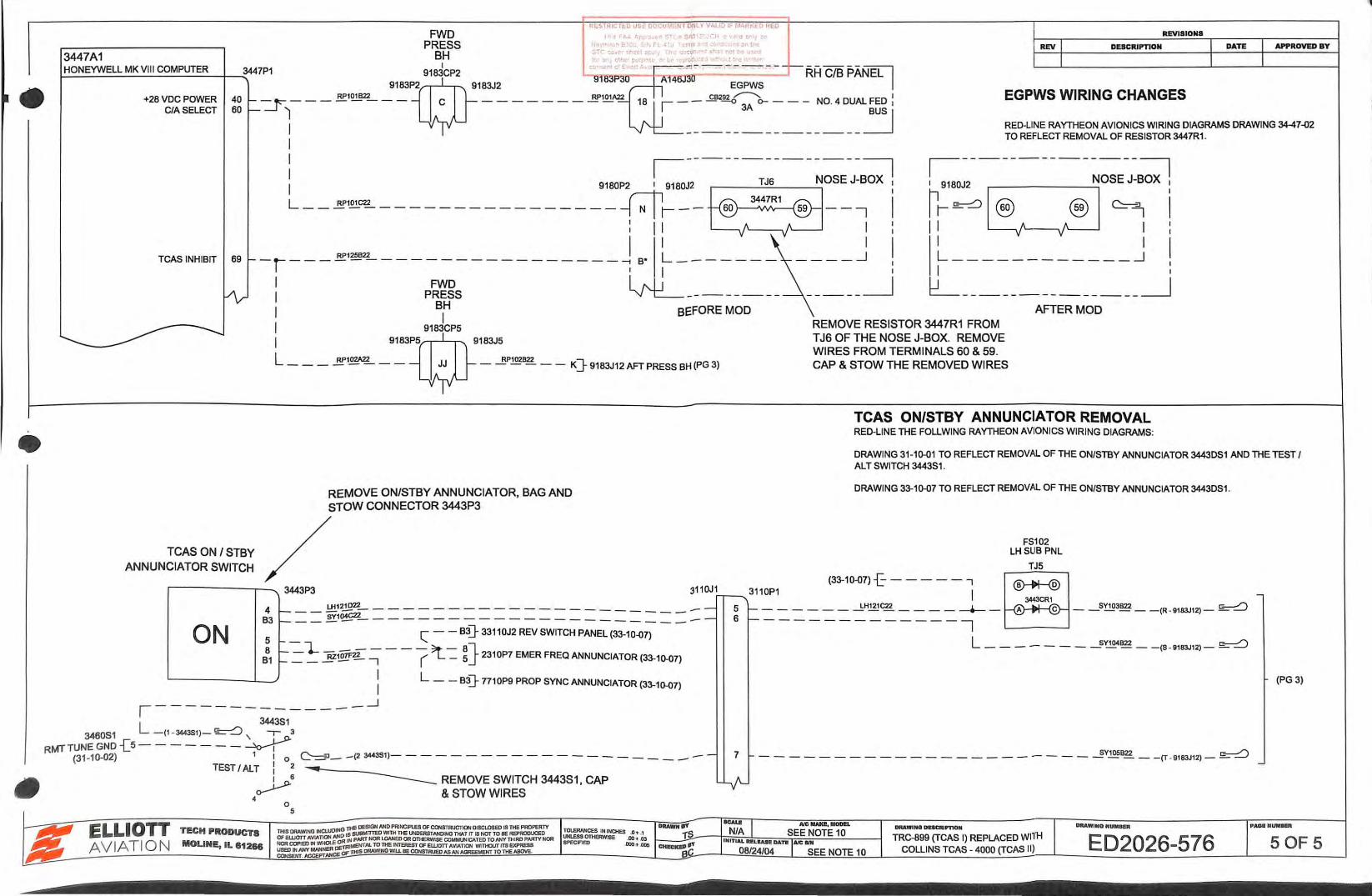
RED-LINE RAYTHEON AVIONICS WIRING DIAGRAMS DRAWING 3447-{)2 TO REFLECT REMOVAL OF RESISTOR 3447R1 .
~--------------:=l
I 9180J2 NOSE J-BOX I
L __ ~ .. ·~----------------~r--~--; !
69 --~---~'"""-----------------~ •• ~------- ____ j !
: P~Rs ~-------- -----~ TCAS INHIBIT
:r~G£ ~; j
I I I L __ _______ _ __ _j
I : b!_ ______________ ~
TCAS ON I STBY ANNUNCIATOR SWITCH
I BH BEFORE MOD I I 9183CP5
I 9183w5 9183J5
L RP102A22 RP102B22 -------- JJ ------ K]-9183J12AFTPRESSBH(PG3)
REMOVE ON/STBY ANNUNCIATOR, BAG AND STOW CONNECTOR 3443P3
REMOVE RESISTOR 3447R1 FROM T J6 OF THE NOSE J-BOX. REMOVE W IRES FROM TERMINALS 60 & 59. CAP & STOW THE REMOVED W IRES
AFTER MOD
TCAS ON/STBY ANNUNCIATOR REMOVAL RED-LINE THE FOLLWING RAYTHEON AVIONICS WIRING DIAGRAMS:
DRAWING 31-10-01 TO REFLECT REMOVAL OF THE ON/STBY ANNUNCIATOR 3443DS1 AND THE TEST I AL T SWITCH 3443S1 .
DRAWING 33-10-07 TO REFLECT REMOVAL OF THE ON/STBY ANNUNCIATOR 3443DS1.
LH SUB PNL
TJ5 /
FS102
r-----~ (33-10-07) t------, ~ --- 3443P3 3110J1 r----.. 3110P1 I B
0 -
4 ....____ LH121D22_ _ _ _ _ _ _ _ _ _ _ _ _ _ _ _ _ _ 5 L__ _ LH121C22 , ~344JCR1c SY103B22 c: _/'\ ,- -- -
104C22 ----- - r- - - - - -- - -- - - - --- - - - - - - (R-9183J12) - ~--'
~r- ~----------- - ----- - 6---- C- -B3]-33110J2REVSWITCHPANEL(33-10-Q;;---- -------------~ 5 f- - ""L * 8} L - - SY104B22 ~
:1 ~ = _ RZ107F22 ---, -- (. L-=
5 2310P7 EMERFREQANNUNCIATOR(33-10-0
7) --- ------ -(S-9183J12)--
ON
: L --B3J-7710P9 PROP SYNC ANNUNCIATOR (33-10-07) (PG 3)
, --------------~ L 3443S1
3460S1 - <1 - 344351)- ~ ' -. 3
RMTTUNEGND -(5-------~ (31-10-02) 1 I 0 ~- -(2 344351)- - -- - - - - -- - - ---____ -- -
TEST/ ALT I 2 ......_____
~6 ----- REMOVE SWITCH 3443S1, CAP
4 & STOW WIRES 0
5
7 ----------------------- _§Y105B22 --(T-9183J12) - ~ -
DIIAWINQ NUIINR PADIINUM ....
• [J
c
-.\'
• B
A
•
8
Jl 3454?2
R-DHE-1 429 A 1 I I 2RG102B22~HT R-DME-1 429 B 2 2RGI 02B22BLU
I•
I• L-CDU-S 429 A 21 2RG109A22\IHT L-CDU-6 429 B 22 2RG109A22BLU
I• RTU-1 429 A 3 2RG110A22\IHT RTU-1 429 B 4 2RG11 OA22BlU
L TUNER TAKE CMD 55 ~lllA22
DME AUDIO CHI H 25 RGI12A22\.IHT DME AUDIO CHI L 26 RG112A22BLU
I•
5 4
4 5 s 7 8 9 10
11 12 13
3140Al 31 40?5--- Jl
t--:'i':-----2RG102A22WHT-------""'frrl39 R-DME-1 429 A t-io-----2RG1 02A22BLU l~l 40 R-DME-1 429 B
L.
31-40-02
1----J 34-60-01 IRPS
~-----] 23-80-01
t----J 23-S0-04
F~D PRESS
BHD 9183CP2
3 .2
+28VDC PO\o/ER H 58 2RGI01C22 14 9183P2[8] 9183J2 3183P31 J31
I------------2RG101822----------- E 2RG101A22 11 DI-E-2 CB (2A)- REF (OPTIONAL) REF 13Q-3S0034 DESIG 24-64-03
+28VDC POWER L 59 2RGl.OGB22
130-340676-0003 HARNESS ASSY (REF)
CHASSIS GROUND S I t----2RG! 07822'----i
STRAP = NO.2 DME 56t---------.
IS NDC301
2RGI06A22---------{l!Nl
lL-:1:_- J 91-84-02
NCS301 16t-----2RG107A22--{fKl
~] 91-84-02
r----,.. J 34-54-01
-- J 91-83-02 91-83-14 C- A146 RH CB PANEL
130-340745-0018 COAX ASSY (REF) FWD ·----------------------------------------------------------------, PRESS BHD 3454PS
DME ANTENNA 3454E2 N0.2 DME ANT
I
r--------------------------, 130-340745-0020 COAX ASSY (REF) : 3454P9 345~9 L---------------------------------------------------------------------------· 3454A2
DME-4000 NO. 2 REF MOUNT GND t------~1 1/BIS----t
~------------~
----------------------------------------------~
NCS302
19t-----2RG114A18~C 20 - J 91-84-02 21 22 23 24
l--------------~6~-----------.------------~-------------r------------~-------------r---------------------------------.------------------
1
[
c
E
..,. TITlE PF(£ RIGHTS FPPt... Y
•
REVISIONS
REV I DESCRIPTION I DATE _l APPROVED BY
I I I
BELOW ~--2-8-~-~-NC-~-:-0~-~-2--2-) --------~ ~1 rf=~~--~~~~---~-f~~11
-1
~~'~JfREFLM:E~~~~:ICSBUS L!~l 11 1~1A20 IJ ,, 7 5 RH TRAY TABLE
POWER GND K I i. "\!l)-111 ' _..--
RS 232 RTS X - - · ,-:,. 7 RS232CTS S ~~~:~-----1~1~1-~00~~~------------------------------------------------------------------------------------------------------------------------------------~~ 8
A· ~E i RS 232 RX RS 232 TX MODEM GND
~· H~lr---~11~1~~3~~~------------------------------------------------------------------------------------------------------------------------------------~:it===~ ; ~ BP1 RJ45 ~
HEADSETGND HEADSET +9VDC
HEADS ETTRU HEADSETCMP
HEADSET RETURN
HEADSETTXA HEADSETRXA HEA DSETTXB HEADSETRXB
FAX DATA LINE (RING) FAX DATA LINE (TIP)
SAT ANTENNA
8 c D E
F
H J T u v w
r---------r-----~,_~l~r-l--~1 1~1~~~~~----------------------------------~~ X ~ 1 ~ 1 111~5~ W-r ~
.._+-H-t-t--1.1~ 1 111.{)()6~ ~
r = r----------t-t-HH-t--\J~I 1 1 1~1~ ~
r-~-ri-t-ri-t-t-ri-~r~~~~ --~11~1~~8~~~------------------------------------{~
BP2
yi}----'-11'-'1__:-004;::..:.:B::22=---{~ ~ 1 2
WHT r-----, r----..:..BR;.;..;N.:__ __ ~ 1
L-----{11~1 111~5822 -W-- ! X = 5
3 4
L-------{~ ~~ 11Hl06B22 .Q-- 6 X = 7
5 6
~---------I.!J ~I 111-009A22 .Q-- 8 7 8
L_ _________ j~BI}-1 _ _ .;_11'-'1--=~~8~8::22=---{.Q--12 12 13 13 11 11 14 14
lJ'-lJ'-
2 YEL GRN 3
RED BLK
ORG BLU
RED GRN BLK
YEL
4
5 6
7 8
~ 3 4 2 5
~
RJ45
LH AFT
RJ11
1 1 2 2
3 3 4 4 5 5 6 6 7 7 8 8
12 12 13 13 11 11 14 14
lJ'-lJ'-
J1
~H~~-------------------------------------~PH ~
SATELLITE A NTENNA
WHT BRN
YEL
GRN
RED BLK
ORG BLU
RED GRN BLK
YEL
-----... 1
2
3 4
5 6
7
L{-,----...,
3 4 2 5
L/y
ELLIOTT AVIATION
TECH PRODUCTS
MOLINE, IL 61266
G THE DESIGN AND PRINCIPLES OF CONSTRUCTION DISClOSED IS THE PRoPERTY THIS ORAWlNG INCLUOIN IS SUBMITTED WITH THE UNDERSTANDING THAT IT IS NOT TO BE REPROOUCED OF ELl! On AVIATION~~ IN pAftT NOR LOANED OR 011-IERVVlSE COMMIJNJCA TEO TO ANY THIRD PARTY NOR NOR COPIED IN w-iOLE RIM..-NTAl TO THE lUTER EST OF EllJOTT AVlA.nC:lr•.l V~THOUT ITS EXPRESS
~~~~7:-'~c'~~~C~~ T~IS DRAW~NG WIU BE CONSTRUED f.SAN AGREEt.ENT TO THE ABOVE
TOLERANCES IN INCHES 0: 1 UNL ESS OTHER\.'VISE 00 : 03 SPECIFIED 000: 005
CHECKED BY
SCALE I AJC MAKE, MODEL
NTS RAYTHEON 8 300 DF\AWN BY
MOO I NITIAL RELEASE DATE JA1C SIN
4/1 1/06 I FL-419 LS
RH FWD
RJ11
DRAWING DESCRI PTION
CABIN COMMUNICATIONS A IRCELL PHONE
DRAWING NUMBER
M2194-111 PAGE NUMBER
1 OF 2
• ELLIOTT AVIATIO N
TECH PRODUCTS
MOLINE, IL 61266
.. r: CABIN 2
11 1-100A22
J .. CA'I_L 3
, ,,_, o, A22N IIl :r : l ........... 11 . ······ ... ··;;~ ·;, 12 J I
6 PIC4NCEL
'- D- REF 3447P3 9 1 111 -102A22N
111-103A22
~ 5 8 111- 11\.!A??
1 Jli ~
7 10 I 11 - 10SA??
4
LMD-1
~ 7
! U j_-tiJ6A22.ti J II 1 4
_I
.c::: 9 3
t__ 6
EL 8 111-00
18 22 _'\REF AIRCELL CB
2
RELAY IS LOCATED BEHIND CABIN CALL
ANN/SWITCH
o:: QC:SIGN AND PRINCIPLES o;: CONSTRUCTtON DISCLOSED IS TI-t:E PROPERTY THIS DRAWING INC LUDING Tr!Sua;JIITTEO WlTH THE UNOERSTAJIOlNG THAT IT IS t-.'QT TO BE REPROOUCEO OF ELLIOTI AVlATION AND IS PART NOR LOAtJEO OR OTHERWISE COMMI..t>IICATED TO ANY THIRD PARTY NOR NOR COP/EO IN VMOlE OR IN ... NT A!.. TO THE INTEREST OF EUJOn AVlAllON 'MTHOUT ITS EXPRESS USED IN AllY MANNER OETRI~.I~S DRAWING Wlll BE CONSTRUED AS~ .AGREEMENT TO THE. ABOVE CONSENT ACCEPT N-ICE Of
TOLERANCES IN INCHES o. 1 UNLESS OTHER\11.1SE. OO :
03 SPECIFIED OOO ~ 00S
DRAWN Oy
Moo LS
AJC MAKE, MODEL
RAYTHEON B300 AJC SIN
FL-41 9
'\.. 7 ]-REF 3447P3
coc KPITCALL _L_
REV
A b._fl ----1111
DRAWI NG DES CRIPTION
CABIN COMMUNICATIONS
CABIN CALL
REVISIONS
DESCRIPTION APPROVED BY
DRAWING NUMBER PAGE NUMOER
M2194-111 2 OF 2
REVISIONS
REV I DESCRIPTION I DATE I APPROVED BY
I I I
• -
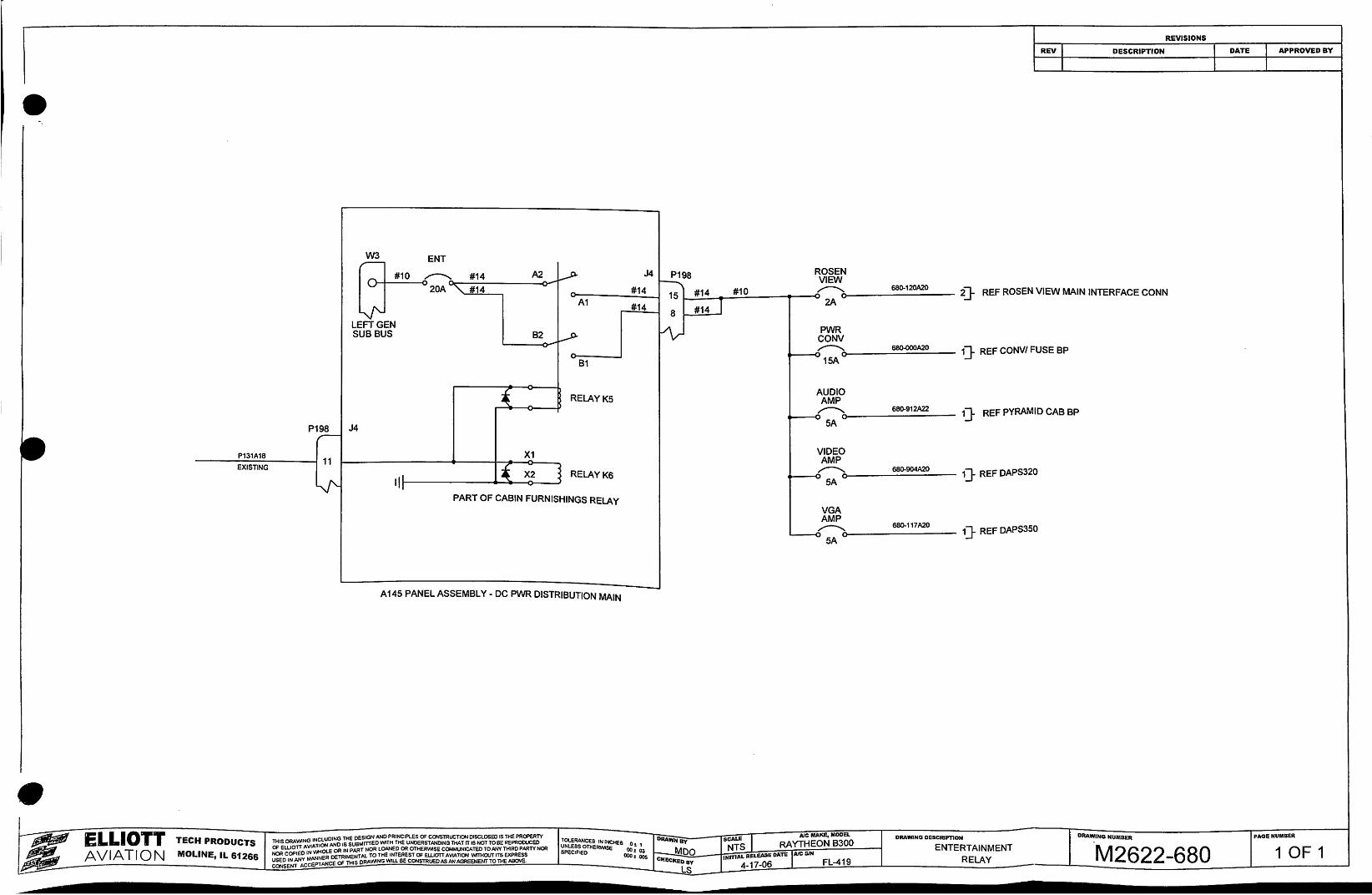
~~ #14 A2 _.P- J4 P198 ROSEN
~ VIEW 20A "' #14 -
~ 680-120A20 2]- REF ROSEN VIEW MAIN INTERFACE CONN #14 15 #14 #10
A1 #14 J 2A-8 #14
LEFTGEN ~ PWR SUB BUS B2 _,-5)- CONV ,---..... 68~A20 1} REF CONV/ FUSE BP "- ~15A.., 81
AUDIO _! RELAYK5 AMP ~ ,---..... 680-912A22 1} REF PYRAMID CAB BP -
~5A-P198 J4 r-
X1 VIDEO P131A18 AMP 11 ( ,---..... 680-904A20 1} REF DAPS320
EXISTING
II' X2 RELAYK6 ~5A-
~ 'I PART OF CABIN FURNISHINGS RELAY
VGA AMP
680-117A20 ,---..... 1} REF DAPS350 L..--6 5A-
A 145 PANEL ASSEMBLY - DC PWR DISTRIBUTION MAIN
• ~ PAGE NUMBER AJC MAKE, MODEL DRAWING DESCRIPTION DRAWING NUMBER ELLIOTT ESIGN AND PRINCIPLES OF CONSTRUCTION DISCLOSED IS THE PROPERTY
G~~~~:_:~s o~ 1 DRAWNay
scALE I RAYTHEON 8300 TECH PRODUCTS THIS ORA'MNG INC~~g ~:tfsMITIED WITH THE UNDERSTANDING THAT IT IS NOT lOBE REPROCUCEO
t---- Moo NTS ENTERTAINMENT M2622-680 1 OF1 ~ OF ELLIOTI AVIATI E OR IN PART NOR LOANED OR OTHERWISE COMMUNICATED TO ANY THIRD PARTY NOR
SPECIFIED o:; ::s INmAL RELEASE DATE lAIC SIN AVIATION MOLINE, IL 61266 NOR COPIED IN v.ti~ DETRIMENTAL TO THE INTEREST OF EWOTT A VIA nON v.ffiiOUT ITS EXPRESS
CHECkEDay FL~419 RELAY ~ ~~~~::~~ ANCE OF THIS DRAWING WILL BE CONSTRUED AS AN AGREEMENT TO THE A!IO'IE.
LS 4~17~06
•
•
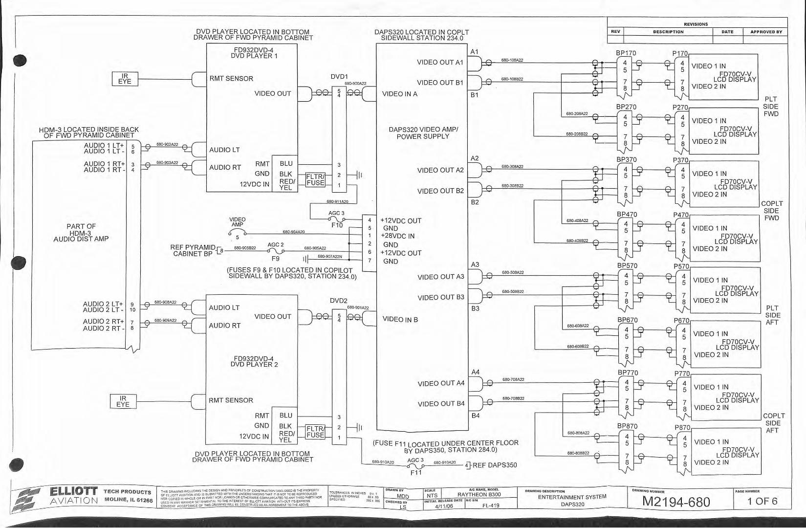
IR I
DVD PLAYER LOCATED IN BOTIOM DRAWER OF FWD PYRAMID CABINET
FD932DVD-4 DVD PLAYER 1
( RMT SENSOR DVD1
DAPS320 LOCATED IN COPLT SIDEWALL STATION 234.0
A1
REVISI ON S
REV DESCRIPTION APPROVED BY
BP170 P)l.Qr----------.., VIDEO OUT A1 rrT--=~~----------------++~~-~ 4 ~~~----4~~ 4 XJ 5 5 ~ 5 VIDEO 1 IN
FD70CV-V
~ ~ 680-108A22
~ ~£'\ 680·108822 I EYE I L ~-;;c ~~~ 5
VIDEO OUT __;-v'>.L- 4
VIDEO OUT B1 ~
VIDEO IN A B1
~ 7 ~ ~ 7 LCD DISPLAY ! 1 LJ_~ 1:_ LJ- VIDEO 2 IN
PLT SIDE FWD
HDM-3 LOCATED INSIDE BACK OF FWD PYRAMID CABINET
A UDIO 1 LT+ A UDIO 1 LT-
A UDIO 1 RT+ AUDIO 1 RT -
PART OF HDM-3
A UDIO DIST AMP
5 r"\
sl-Y
3 r"\
4 1--Y
5B0-902A22 ,...... r-~ AUDIO LT
680-903A22 ,...... r-~ AUDIORT
RMT
GND
BLU 3
BLK nFLTR/r 2 HI' REDI~FUSE~ 1 ~ YEL 12VDC IN
VIDEO AMP ~
0 5
I 680-904A20
AGC2 REF PYRAMID_r-8 _....=;s 8:..:..o.=so=58=22'---<' 68o.9o5A22
L--
680-91 1A20
F1 0
CABINET BP ~ . , F9 II f 680-907A22N
.--- 5
1
~ 2
6
7
(FUSES F9 & F10 LOCATED IN COPILOT SIDEWALL BY DAPS320, STATION 234.0)
AUDIO 2 L T + 9 ,...... 680.908A22 ,.., ,-DVD2
DAPS320 VIDEO AMP/ POWER SUPPLY
BP270 PJQQ,..----------~ 580-208A22 ~ ,.--- £'\ ,....,.
L....:..:..:....::..:.=-=:-f+-'T'---i ~ Cf 't_ ~ VIDEO 1 IN
FD70CV-V
87 1-l f..-+-Q-~~~ 7 LCD DISPLAY
1---J ~ 8 VIDEO 2 IN ~ l)'--t__ _ _J
680-208822 £'\
A2 BP370 PjQQ,..--------------~ h ~ 580-308A22 ~ ,.-- £'\ ~
VIDEO OUT A2 l--)1-+-l--===--------+'r'+l...--~ ~ 1-~f-+---.f..-4--l't._ ~ VIDEO 1 IN
f--.... 6 I FD70CV-V 1 \ ~ 580-3oee22 r--.. 7 r... ~ 7 LCD DISPLAY
VIDEO OUT B2 l--J XJ 8 I-T' y 8 VIDEO 2 IN B2 '.L ~ lJ'L__ _ _ __ ___J COPLT
+12VDC OUT GND
+28VDC IN GND
+12VDC OUT GND
SIDE ~0 PflZQ.---------------~ FWD
L....:::68:.:..0-4..:..:0.:::..8A22=-t-t-~----! 4 ~~"'----4~~ 4 1'_ 5 ~ ~ 5 VIDEO 1 IN
FD70CV-V 7 ~-!--+-"'--~~ 7 LCD DISPLAY LJ-1-J' 'E:LJ. VIDEO 2 IN
A3 B P5 70 P ,§.Z.Q .---------------__,
680-408822 ~
h ,..... 680-508A22 ~ ,.--- ~ ,....,. VIDEO OUT A3 l--)f--f...=t--==~------+'r:T~l-----< ~ 1-~f-+---y+-+--~ ~ VIDEO 1 IN
f--.... Q I FD70CV-V 1 \ ~ 680-
508822 "' 7 "' ~ LCD DISPLAY
AUDIO 2 LT - 10 1--Y ~ AUDIO LT
AUDIO 2 RT+ AUDIO 2 RT -
? ,-... 680-909A22 ,-...
VIDEO OUT B3 ~ X J L ~.~ y ~ VIDEO 2 IN
B3 '.L ~ - ~L---------~ ~0 P~.---------------~
r--- 680-901A22
VIDEO OUT I) "'"' 5 ~ _r 4 _....~ VIDEO IN B
PLT SIDE AFT
a~ ~ AUDIORT
l--------l../~
FD932DVD-4 DVD PLAYER 2
I IR 11---------ll RMT SENSOR EYE I '--
RMT
GND
12VDC IN
BLU 3
BLK DFLTRl- 2 H ll RED/ FUSE~ 1 ~ YEL
L--
~s8_o~_o_8A22 __ t+"'--~ 4 ~++~----~,....,.~ 4 'T' 5 ~ ~ 5 VIDEO 1 IN FD70CV-V
7 "' ~ 7 LCD DISPLAY 8 ¥ y VIDEO 2 IN
~~ ~LJ.~------~ 68~08822 ~
A4 B P770 P)l.Q.,..---------------. h ~ 580-708A22 r-, ~ ~
VIDEO OUT A4 ~1-Pf-.:::::::::.:.:::::::::::.:__ ______ -f:'r:M-_ ·---1 ~ ~-<_:yH----.A--J't'.= ~ VIDEO 1 1N
h ,....,. ~J FD70CV-V VIDEO OUT B4 I p 680-708822 '>.,1 I 7 I Q V 7 LCD DISPLAY
~ A J 8 f--l ~ 8 VIDEO 2 IN B4 '.L ~ L "'- COPL T '1 - L__ ____ ____, SIDE
(FUSE F11 LOCATED UNDER CENTER FLOOR BY DAPS350, STATION 284.0)
BP870 P870.---------------~ AFT 580-808A22 ~ r-'- £'\ ~
t___:_:_:_~'.L-j-----1 45 1-1 -yH---A-ly- 4 LL---1 f--l ~ 5 VIDEO 1 IN
FD70CV-V 680-808822 r.:... DVD PLAYER LOCATED IN BOTIOM
DRAWER OF FWD PYRAMID CABINET AGC3 '----=6=80..::.·91:.,:::0A2::=,0~-A"' n--_.:5:::::80:....:·9....::10.:.=A2;::...0 - DR E F DAP s 350
7 1-e-~--"'A-l 7 LCD DISPLAY 8
I 'Y y f--l ~ 8 VIDEO 2 IN
+ ~L------'
ELLIOTT AVIATIO N
TECH PRODUCTS
MOLINE, IL 61266
THIS DRAWING INCLUDING THE DESIGN AJ\10 PRINCIPLES Of CONSTRUCTION DISCLOSED IS THE PROPERTY OF ELUOTI A VIA l iON AND IS SUBMITTED WITH THE UNOERSTAN'OING THAliT IS NOT TO BE REPRODUCED NOR COPIED IN WriOtE OR IN PART NoR LOANED OR OTHERWI SE COMMUNICATED lOM'Y THIRD ?AATY NOR USED IN ~y I~ANNER OE1 RIMEN1Al TO THE INTEREST Of EUIOTT AVLt..TION WITHOUT ITS E.XFRESS CONSENT ACCEPTANCE OF THIS ORA WING WLL BE CONSTRUED AS~ AGREEMENl TO "THE ABOVE
F1 1
DRAWING DESCRJPTION
ENTERTAINMENT SYSTEM
DAPS320
DRAWING NUMBER P.a.GE NUMBER
M2194-680 1 OF 6
I -
R c
REF#
•
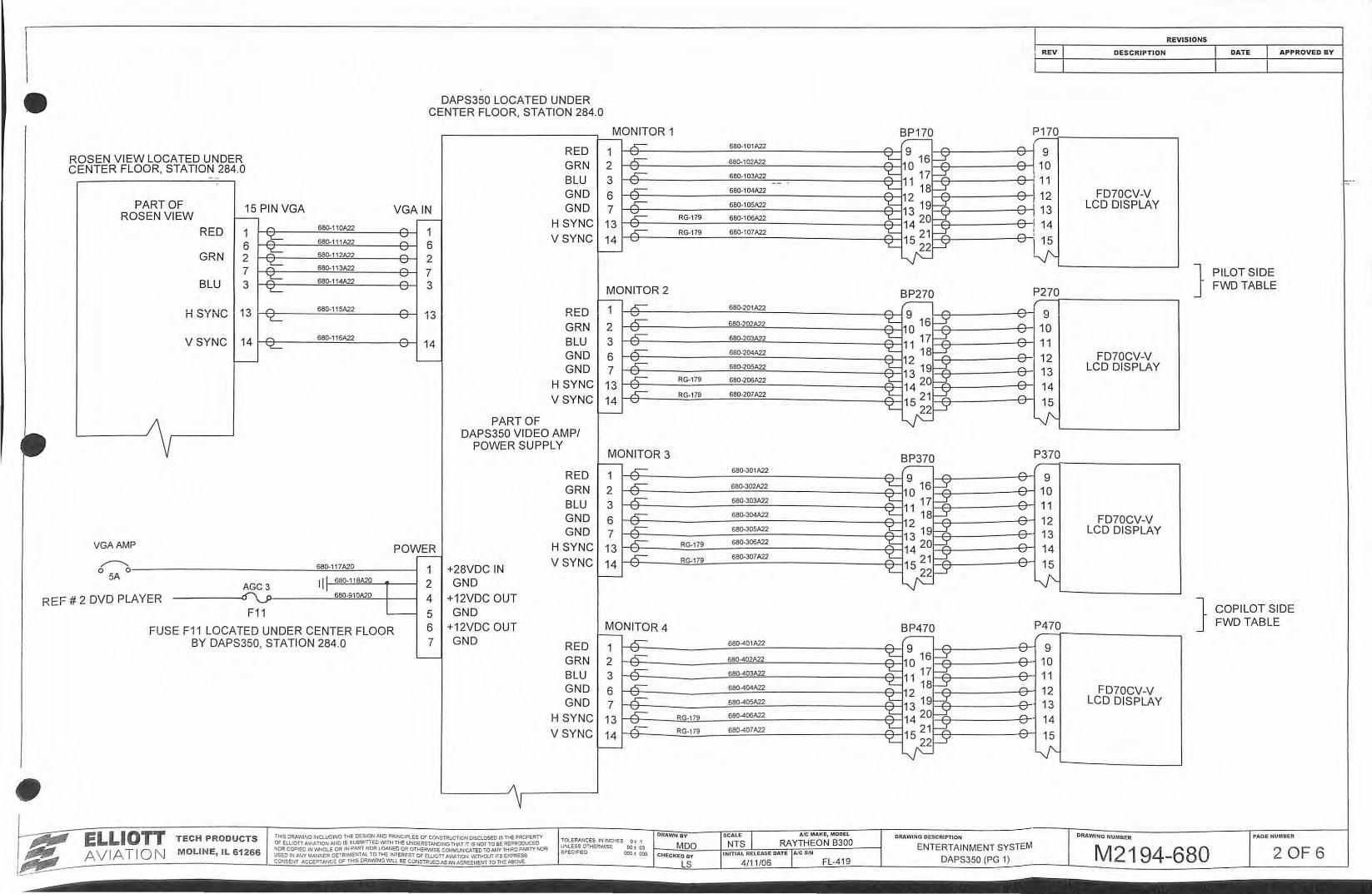
DAPS350 LOCATED UNDER CENTER FLOOR, STATION 284.0
RED OSEN VIEW LOCATED UNDER GRN ENTER FLOOR, STATION 284.0 - ., BLU '
GND PART OF 15 PIN VGA VGAIN GND
ROSEN VIEW f-- ,--- H SYNC RED /'""\ 660-110A22 /'""\ 1 k- ~
1 V SYNC 6 660-111A22 6
GRN 2 ~ 680-112A22 ~ 2 ~
v
7 660-113A22 r..
~ ~ 7
BLU 3 660-114A22 3 'L '-'
H SYNC 13 J"\ 660-115A22 ,..., RED 'L '-' 13 GRN
VSYNC 14 ,..., 680-116A22 ,..., BLU ~ '-' 14
GND I-- -
GND H SYNC VSYNC
PART OF DAPS350 VIDEO AMP/
POWER SUPPLY
RED GRN BLU GND GND
VGAAMP POWER H SYNC .---
VSYNC ~ 680-117A20 1 +28VDC IN 0 0 5A Ill 680-11 8A20 GND AGC3
I [ 680-91 OA20 2
2 DVD PLAYER ~ 4 +12VDC OUT F11 L---- 5 GND
FUSE F11 LOCATED UNDER CENTER FLOOR 6 +12VDC OUT
ELLIOTT AVIATION
BY DAPS350, STATION 284.0 7 GND
T ECH PRODUCTS
MOLIN E, IL 61266
L.___
THIS DRAWING INCLUDING THE OESIGtl AND PRINCIPLES OF CONSTRUCTION OtSCLOSEO tS THE PROPERTY OF ELLIOTI AVIATION AND IS SUBMIITEO WITH THE UNDERSTANDING THAT IT IS NOT TO BE REPRODUCED NOR COPIED IN INHOLE OR IN PARi NOR lOANED OR OTHERVII SE COM.\AUNICATEO TO AllY TH~RD PAATY tiiOR USED IN ANY MAt·mER OETRtMENlAl TO THE INTEREST OF E.Won AVIATION V~THOUT rTS EXPRESS CO"JSEIIT ACCEPTANCE Of THIS ORAVIING Vlll BE CONSi RlJEOAS J.J;J AGREEME~fl TO Tl1E ABOVE.
RED GRN BLU GND GND
H SYNC VSYNC
MONITOR 1 1--
_r:;-1 ~ 2 ~ 3 ~ 6 &-7 ~ 13 ~
14 '-'
I--
MONITOR 2 I--
,.r::;:-1 '-'
2 ,.r::;:-
K-3 ~ 6 ~ 7
13 ~ _£. 14 '-'
I--
MONITOR 3 '---- ~
1 '-' 2 ~ ~ 3 ~ 6 k 7
13 ~ _E-14 '-'
I--
MONITOR 4 1--_r::;--
1 '-' 2 _r:;-
_E.-3 ~ 6
7 k 13 .k
K_ 14 \..,J
I--
680-10 1A22
6B0-102A22
660-103A22 -
660-104A22
660-105A22
RG-179 660-106A22
RG-179 660-107A22
660-201A22
6B0-202A22
6B0-203A22
6B0-204A22
680·205A22
RG-179 660-206A22
RG-179 660·207A22
660-301A22
660-302A22
660-303A22
660-304A22
660-305A22
RG-179 660-306A22
RG-179 660-307A22
680-401A22
660-402A22
680-403A22
660-404A22
680-405A22
RG-179 680-406A22
RG-179 680-407A22
REV
BP170 P170 _,..---
_,...... 9 r- ,...,
~10 16~ '-' 9 ,...,
10 ~1117~
v _,......
11 \..,J
~ 188: ,..., 12
k 12 19~ >;:J ,...,
13 ~ 13 20h( \..,J
r-'-' 14 'L 14 ~
"' 15 21 ,..., ,
v~ 'L~P'
BP270 _,..---
r-.. 9 ,..., /'""\ \..,J
~10 16~ r-'-'
::f= 11 17cy /'""\ -= ~ 18~ r.. ~1 2 ~ 13 19hz k 1420hz ~.
\..,J
~ 15 211-t ,..., v
'L 22LY vc BP370 r--
I"'\_ _,...... 9 roo. '-'
~10 16~ I"'\_
""' ~ 11 17r=;( /'""\ . \..,J
~ 18~ ,..., 12 -v
k-13 19f-X r..
~ 14 20h( ~ \..,J
~ 15 21h!: r'i "Q
'L~P'
BP470 _,..---
n r- 9 /'""\ ~ 10 161---;(
--v £'>.
~1117~ - \...)
,..,_ ~ 18~
'Q
/'""\
~12 19hz ~ ~ 13 20hz ~ ~ 14 f-.;( \..,J
"' 1521 I"'\_
'L~~ 'Q
DRAWING DESCRIPTI ON
ENTERTAINMENT SYSTEM
DAPS350 (PG 1)
P270
9 10 11 12 13 14 15
~
P370
9 10 11 12 13 14 15
lJ'-
P470
9 10 11 12 13 14
15
lJ'-
DESCRIPTION
FD70CV-V LCD DISPLAY
FD70CV-V LCD DISPLAY
FD70CV-V LCD DISPLAY
FD70CV-V LCD DISPLAY
DRAWING NUMOER
REVISIONS
} PILOTSIDE FWD TABLE
APPROVED BY
} COPILOT SIDE FWD TABLE
PAGE NUMBER
M2194-680 2 OF 6
ELLIOTT AVIATIO N
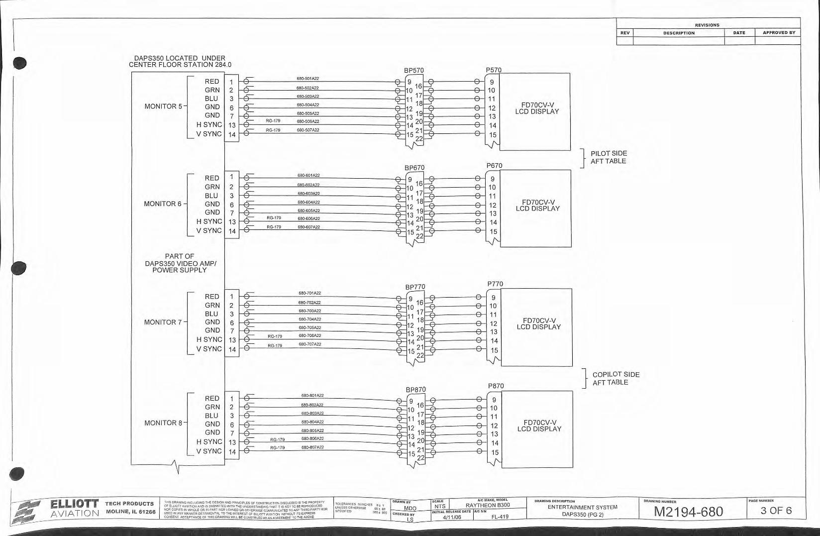
DAPS350 LOCATED UNDER CENTER FLOOR STATION 284.0
,-- r-
RED 1 GRN 2 BLU 3
MONITOR 5 - GND 6 GND 7
H SYNC 13 VSYNC 14
'---,---
I--,--RED 1
GRN 2 BLU 3
MONITOR 6- GND 6 GN D 7
H SYNC 13 VSYNC 14
'--t---
PART OF DAPS350 VIDEO AMP/
POWER SUPPLY
1----RED 1 GRN 2 BLU 3
MONITOR 7 - GND 6 GND 7
H SYNC 13 VSYNC 14
'--t---
--RED 1 GRN 2 BLU 3
MONITOR 8- GND 6 GND 7
H SYNC 13 V SYNC
'---14
1---
~ 580·501A22
~ 680·502A22
~ 680·503A22
~ 680-504A22
~ 58().505A22
~ RG-179 680-506A22
~ RG-179 68().507A22 \.../
~ 58().60 1 A22
~ 680-602A22
~ 68().603A22 '-'
~ 68Q.604A22
~ 580.SOSA22
~ RG-179 680-606A22
~ RG-179 680-607A22 \.../
,r::- 68().701A22
~ 680-702A22
~ 68().703A22 '-' ,r::- 680-704A22
~ 68().705A22
~ RG-179 68().706A22
~ RG-179 680-707A22 -=
~ 680-801A22
~ 680-802A22
~ 68().803A22
~ 680-804A22
::E-- 680-805A22
~ RG-179 680-806A22
~ RG-179 680-807A22 \.../
TECH PRODUCTS
MOLINE, IL 61266
~!S DRAWING INCLUDING THE DESIGN AND PRINCIPLES Of CONSTRUCTION DISCLOSED IS THS. PRoPERN Of EUIOTI AVIATION AND IS sumAinEO WlTH THE UNOERST ANDING mAT IT IS NOT TO BE REPRODUCED ~lOR COPIED IN WrlOLE OR IN PART NOR LOANED OR OTHERWISE COMMUNICAit:.O TO ANY THIRD PAATY NOR USEO IN ANY MANNER OETRIMEHTAl TO THE INTEREST Of ELUOTT AVlATION \NlTHOVi !TS EXPRESS CONSENT ;..cCEPT AlljCE OF THIS DRAWiNG Wlll BE CONSTRUED AS AN AGREEMENT TO THE A90VE
BP570 :;;..:--=-:--: ,..... 9 ,....,. ~1 0 16~ ~ 1 1 17=t ~ 1 8~ k- 12 191=-X ~ 13 20~ ~ 14 ~ r:; 1521 'LLJ3:-P'
~ ,....,. 9 ,....,. ~1 0 16~ ~ 1 11 7~ ;= 18~ ~ 12 19~ ~~~20~ ~ 21~ 'C 1522~
lJC
~ ,..... ,.....
~1~ 16~ ~1 1 17~ ~ 18:.;( ~12 19~ A=1 3 20~ ~14 ~ '"'1 5 21 'C 221=5'
~
~ /"'\ 9 " ~ 16~ ~10 ~ r::. 11 17 ~ 18~ ~12 19~ ~1 3 20~ ~14 21=z-'l:::: 15 22 3
~
P570 ~
\.../ 9 ~ 10 \.../ ,.....
11 \.../
,..... \.../ 12 ,....,. \.../ 13 ,....,. \.../ 14 ~
\.../ 15
lJ'--
P670 ,..... '-' 9 ,.....
10 '-' ,....,.
11 'J
~
12 ~ ~
13 '-' 14 ,....,. \.../ 15
V'-
P770 ,.....
-.:::T 9 ,....,. ~ 10 ~
'-' 11 ,....,. \.../ 12 ,....,.
13 \.../ ,....,. \.../ 14 ,..... \.../ 15
'--1'-
P870 ,....,. = 9 ,....,. \.../ 10 ,....,. \.../ 11 ,....,. \.../ 12 ,....,. \.../ 13 ,..... \.../ 14 " \.../ 15
--J'-
FD70CV-V LCD DISPLAY
FD70CV-V LCD DISPLAY
FD70CV-V LCD DISPLAY
FD70CV-V LCD DISPLAY
DRAWING DESCRIPTION
REV
} PILOT SIDE AFT TABLE
} COPILOT SIDE AFT TABLE
ENTERTAINMENT SYSTEM DAPS350 (PG 2)
REVIS IONS
DESCRIPTION APPROVE D BY
DRAWI NG NUMBER PAGE N U MBER
M2194-680 3 OF 6
\ REVISIONS
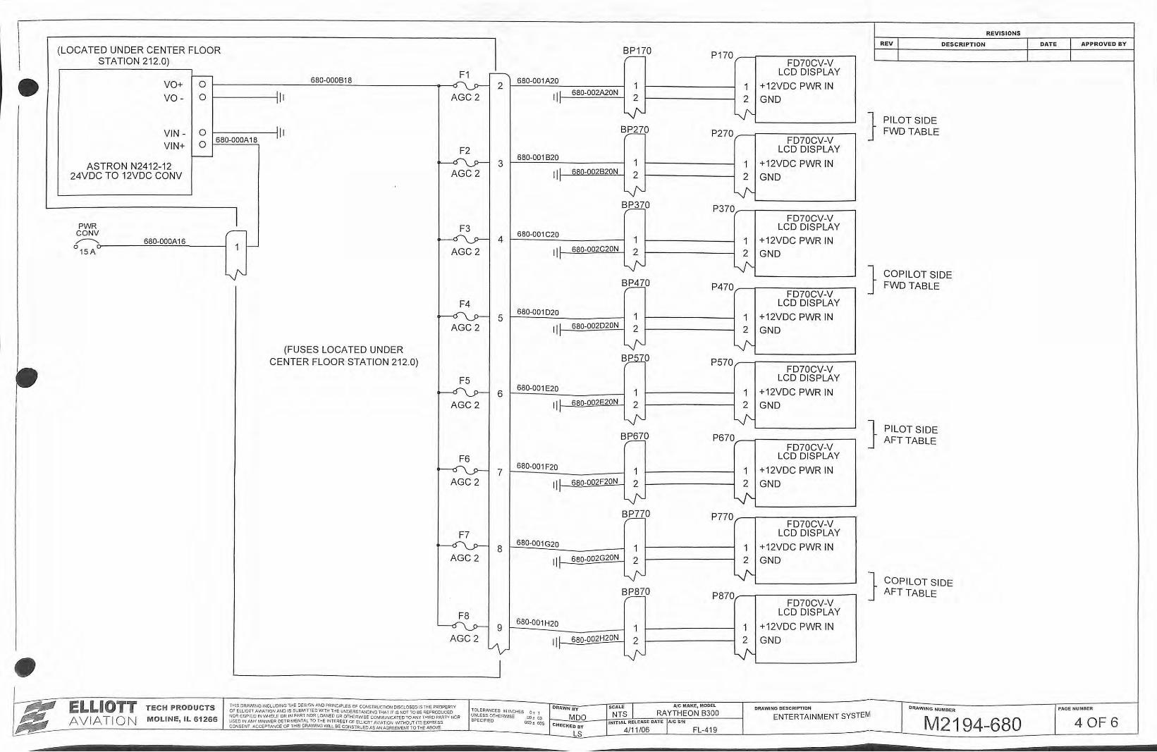
REV I DES CRIPTION I DATE l APPROVED BY I (LOCATED UNDER CENTER FLOOR BP170 P170 I I l I r-STATION 212.0) FD70CV-V F1 r-----, LCD DISPLAY c- 680-000818
0\y--- 680-001A20 - VO+ 0 2 1 1 +12VDC PWR IN 111 111 680-002A20N vo - 0 AGC2 II 2 2 GND
~ lJ'- } PILOT SIDE VIN - 0 111 Bj:llO P270 FWD TABLE
680-000A18 I FD70CV-V VIN+ 0
F2 LCD DISPLAY 1--
~ 680-001820
1 1 +12VDC PWR IN ASTRON N2412-12 3 24VDC TO 12VDC CONV AGC 2 ill 680-002820N 2 2 GND
~ lJ'-BJ.TIO P370
I FD70CV-V PWR F3 LCD DISPLAY
CONV r--~ 4
680-001C20 1 +12VDC PWR IN ,---........ 680-000A16 1
0 15A ~ 1 1--AGC2 111 680-002C20N 2 2 GND II
~ ~ '+ } COPILOT SIDE ~0 P470 FWD TABLE
FD70CV-V F4 LCD DISPLAY
~ 5 680-001020 1 1 +12VDC PWR IN
AGC2 II L 680-002D20N 2 2 GND 'I
V'- ~ (FUSES LOCATED UNDER CENTER FLOOR STATION 212.0) BP 0 P570
FD70CV-V F5 LCD DISPLAY
~ 6 680-001 E20 1 1 +12VDC PWR IN
AGC2 II L 680-002E20N 2 2 GND 'I
V'- lJ'-} PILOT SIDE
B):§.IO P670 AFT TABLE FD70CV-V
F6 LCD DISPLAY
>-----Q\_y- 7 680-001F20
1 1 +12VDC PWR IN AGC2 II L 680-002F20N 2 2 GND
' I
V'- ~ ~0 P770
FD70CV-V F7 LCD DISPLAY
~ 8 680-001G20
1 1 +12VDC PWR IN AGC2 qL 680-002G20N 2 2 GND
'I
V'- lJ'- } COPILOT SIDE ~0 P870 AFT TABLE
FD70CV-V F8 LCD DISPLAY
~ 9 680-001H20
1 1 +12VDC PWR IN AGC 2 IP 68Q-002H20N 2 2 GND vv ' I
V'- lJ' • I
~ ELLIOTT TECH PRODUCTS THIS DRAWING UlCLUOING THE DESIGN AND PRINCIPLES Of CONSTRUCTION DISCLOSED IS THE PRO?ERTV DRAWN BY SCALE I AJC MAKE, MODEL DRAWIN G DESCRIPTION D~WING NUMBER P AGE NUMBER OF ELLIOTT AVIATION AND IS SUBMITIED WlTH THE UNDERST.t.NOtNG THAT IllS NOT TOBE REPRODUCED TOLERANCES IN INCHES 0: 1 NTS RAYTHEON 8300 ENTERTAINMENT SYSTEIVI ~ NOR COPIED IN WHOLE OR IN PART NOR LOANED OR OTHERWISE COMMlJ'NtCATEO TO f:.J'JY THIRD PARTY NOR UNLESS OTHERWISE oo .
03 MOO M2194-680 4 OF 6 AVIATIO N MOLINE, IL 61266 USED IN ANY MA.tlNER DETRIMENTAl TO THE INTEREST OF ELUOTI AVlAnON 'MTHOUT liS EXPRESS SPECIFIED OOO; ~
CHec~eo ay I NITIAL RELEASE DATE lAJC SIN
~ CONSENT ACCEPTf\NCE OF THIS ORAIMNG IMU BE COJ~STRUED AS AN AGREEMENT TO THE ASOVE.. 4/11 /06 FL-419 LS
REVIS IONS
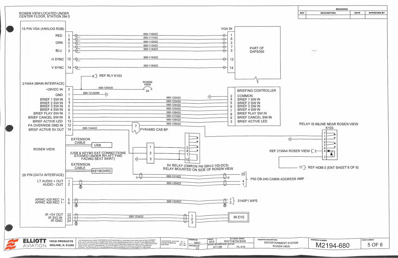
ROSEN VIEW LOCATED UNDER R EV I DES CRIPTION I DATE I APPROVED BY
CENTER FLOOR, STATION 284.0 I I I
• 15 PIN VGA (ANALOG RGB) VGA IN 1--- .---
RED 1 ,.... 680-110A22 ,.... 1
6 ~ 680-1 11A22 ;::_
6 GRN 2 ~ 680-112A22 ~ 2
~ '-'
7 680-113A22 ,.... 7
~ '-' PART OF BLU 3
680-114A22 " 3 ~ '-' DAPS350
H SYNC 13 ,.... 680-115A22
" ~ '--' 13
VSYNC 14 ,.... 680-116A22 ,.... ~ '--' 14
f--8]- REF RLY K103
'---
21WA4 (MAIN INTERFACE) ROSEN VIEW
1-- 680-120A20 ~ +28VDC IN 2 0 0
BRIEFING CONTROLLER :11
2A
GND 1 680-121A20N
II ~ 2 COMMON BRIEF 1 SW IN 3
680-1 22A22 4 BRIEF 1 SW IN BRIEF 2 SW IN 4 680-1 23A22
5 BRIEF 2 SW IN BRIEF 3 SW IN 5 680-124A22 6 BRIEF 3 SW IN BRIEF 4 SW IN 6 680-1 25A22
7 BRIEF 4 SW IN BRIEF PLAY SW IN 7 680-126A22
8 BRIEF PLAY SW IN BRIEF CANCEL SW IN 8 680-127A22
9 BRIEF CANCEL SW IN BRIEF ACTIVE LED 13 680-128A22
3 BRIEF ACTIVE LED
• PA OVERRIDE GND IN 12 ~ 680-129A22 RELAY IS INLINE NEAR ROSEN VIEW
BRIEF ACTIVE 5V OUT 14 680-134A22 ~PYRAMID CAB BP K103
- IB EXTENSION :=J I I ~ CABLE .--- ~
~8 USB I 3:=J 1 ROSEN VIEW
(USB & KEYBD EXT CONNECTIONS 2 I 4 ~ REF 21WA4 ROSEN VIEW { 2 - :~ STOWED UNDER RH AFT FWD l 1 D FACING SEAT SKIRT) II: 3 10
EXTENSION '----
CABLE 5V RELAY (OMRON PN G6H-2-100-DC5) 17} REF HDM-3 (ENT SHEET 6 OF 6)
KEYBOARD-I RELAY MOUNTED ON SIDE OF ROSEN VIEW
26 PIN (DATA INTERFACE) c.. C>.
2;} ;g 680-131A22 -GJ-:J 1--- P50 DB-240 CABIN ADDRESS AMP L T AUDIO + OUT 1 C>. c..
AUDIO- OUT 2 R 680-130A22 J ~l
ARINC 429 REC 1+ 5 ...-.. C>. 1}
ARINC 429 REC 1 - 6 ~ 680-132A22
T2 3140P1 lAPS
r--IR +5V OUT 22 -=
I I IR SIG IN 23 t1;1 680-133A22
1iE 1 IR EYE
IR GND IB 2 24 ~ 3 • t--- -= ......_
~~ ELLIOTT THIS DRAWING INCLUDING THE DESIGN AND PRINCIPLES OF CONSTRUCTIOO DISCLOSED IS THE PROPERlY DRAWN BY SCALE I AJC MAKE, MODEL DRAWING DESCRIPTION DRAWING NUMBER PAGE NUMBER
Jlld~ TECH PRODUCTS OF ELUOTI AVIATION AND IS SUBMinEO WITH THE UNDERSTANDING THAT IT IS NOT TO BE REPRODUCED TOLERANCES IN INCHES 0 :: 1
MOO NTS RAYTHEON 8300 ENTERTAINMENT SYSTEM
~ NOR CO?! EO IN V\1-iOl.E OR IN PART NOR LOANED OR OTHERWISE COMI-AUNICATEO TO ANY THIRD PARTY NOR UNlESS OTHER'MSE 00 !. 03
M2194-680 5 OF 6 AVIATION MOLINE, IL 6 1266 SPECIFIED 000 ! 005 INITIAL RELEASE DAT E AJC SIN USED IN ~y fAANNER DE TRIMENTAL TO THE INTEREST OF EUJOTI AVIATION \MTHOUT ITS EXPRESS CHECKED BY ROSEN VIEW
J£b! CONSENT ACCEPTANCE Of THIS DRAWING WIU BE CONSTRUED AS AN AGREEMaiT TO THE ABOVE LS 4/11 /06 FL-419
•
•
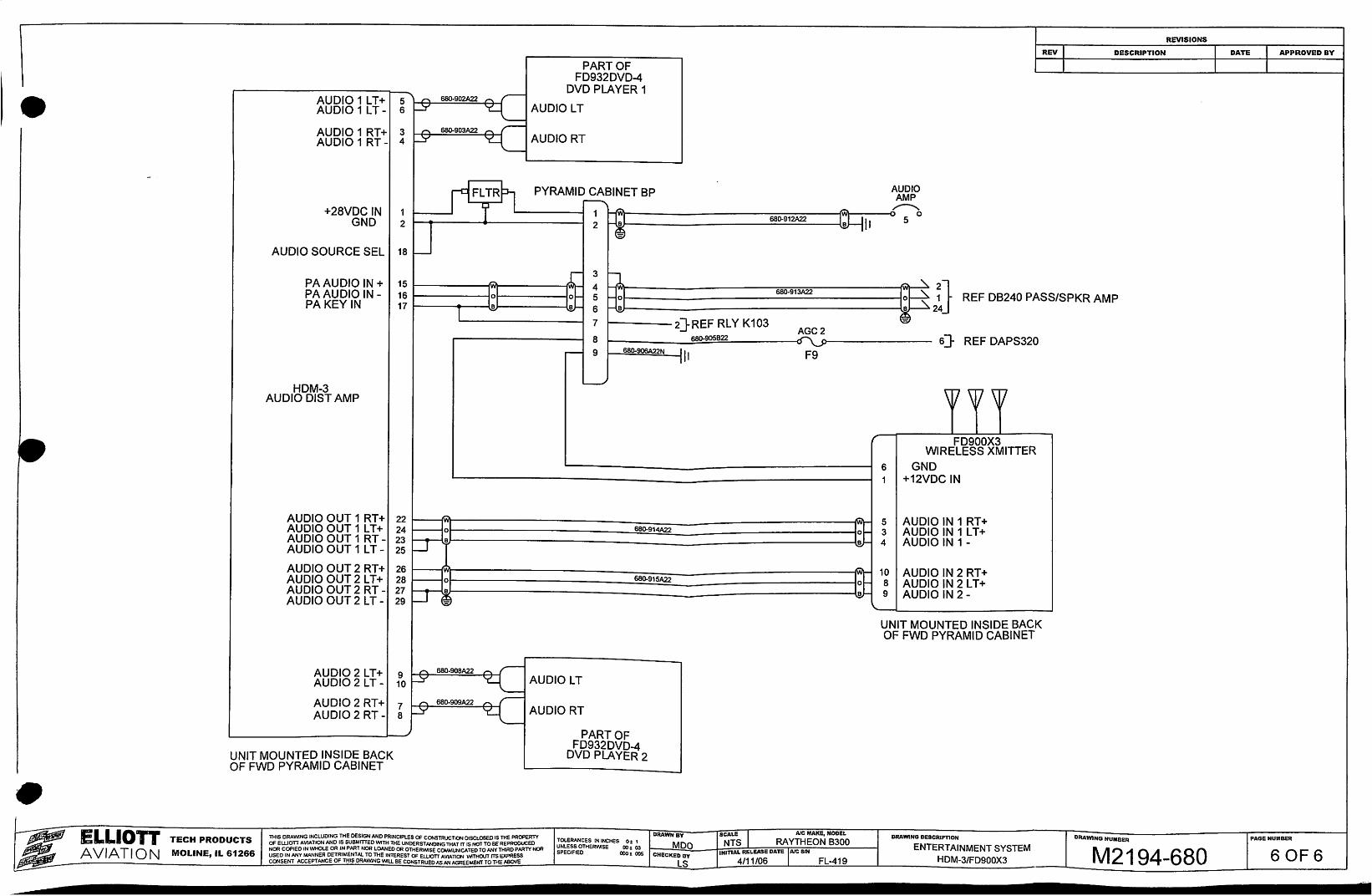
PART OF FD932DVD-4
_ DVD PLAYER 1 AUDIO 1 L T + 5"""' ___c.. sao-oo2A22 "' r AUDIO 1 L T- 6 t-_yH--==-==-~~ AUDIO L T
680-903A22 1""\. ,-
AUDIO 1 RT + 3 ~ 'C.....~ AUDIO RT AUDIO 1 RT- 4 1-Y '--
FL TR PYRAMID CABINET BP A~B~0
+28VDC IN GND
1 2
9 ~------------~~~~~----------------------~~~----~~~~--~~~5 0 1 HJ 680-912A22 J ~LJ, t----.---4-------1 2 I ®r------____;;,~...;;:::;._-----\.w-. I
AUDIO SOURCE SEL 18 ~
3
REV DESCRIPTION
-~ ~
1~1 i± l l~l
PA AUDIO IN + 15 1-------IWI-------riNI-f
PA AUDIO IN- 16 1---------1 PA KEY IN 17 t---~----1
4 5 6
7
n ~
680-913A22
2}REF RLY K103
1-------------------J:~ ~} REF DB240 PASS/SPKR AMP ~------------------------------------------------------------------------~~~24
-=~
HDM-3 AUDIO DIST AMP
AUDIO OUT 1 RT + AUDIO OUT 1 LT+ AUDIO OUT 1 RTAUDIO OUT 1 LT-
AUDIO OUT 2 RT + AUDIO OUT 2 LT+ AUDIO OUT 2 RTAUDIO OUT 2 LT-
AUDIO 2 LT+ AUDIO 2 LT-
AUD102 RT+ AUDIO 2 RT-
UNIT MOUNTED INSIDE BACK OF FWD PYRAMID CABINET
8 680-905822
,.._ 9 680-!!QSA22y II
L__....l
AGC2 ...
F9
6 1
22 ~ 10 5 24 l---Jor---------------------------~S~BD-~9~14~~~--------------------------~~~~ 3
~; b-lrB .w- 4
26 ~ 10 28 ~or---------------------------~68~0-~9~15~~~----------------------------~~~~ 8
6} REF DAPS320
FD900X3 WIRELESS XMITTER
GND +12VDC IN
AUDIO IN 1 RT + AUDIO IN 1 LT+ AUDIO IN 1-
AUDIO IN 2 RT + AUDIO IN 2 LT+ AUDIO IN 2-27 ~~ W- 9
29 ~ ~ '-~--------------------~
g ~ 660-90BA22
10 ~
? r. 6BD-909A22
sl-Y
_,-~ AUDIOLT
_,-~ AUDIORT
PART OF FD932DVD-4
DVD PLAYER 2
UNIT MOUNTED INSIDE BACK OF FWD PYRAMID CABINET
DRAWING DESCRIPnON DRAWING NUMBER
REVISIONS
ELLton TECH PRODUCTS
AVIATION MOLINE, IL 61266
THIS ORAWNG INCLUDING THE DESIGN AND PRINCIPLES OF CONSTRUCTION DISCLOSED IS THE PROPERTY OF EWOTT AVIATION AND IS SUBMITTED WITH THE UNDERSTANDING THAT IT IS NOT TO BE REF'ROOUCEO NOR COPIED IN 'MiOI.E OR IN PART NOR LOANED OR OTHERWISE COMMUNICATED TO ANY THIRD PARTY NOR USED IN ANY MANNER DETRIMENTAl. TO THE INTEREST OF ELLIOTT AVIATION v.1THOVT ITS EXPRESS CONSENT ACCEPTANCE OF THIS DRAWNG WILL BE CONSTRUED AS AN AGREEMENT TO THE ABOVE
ENTERTAINMENT SYSTEM HDM-3/FD900X3 M2194-680
APPROVED BY
PAGE NUMBER
6 OF6