2.11 mass flowmeters, coriolis - kishore … · 2.11 mass flowmeters, coriolis 227 is the rotation...
TRANSCRIPT

225
2.11 Mass Flowmeters, Coriolis
CATHY APPLE
(1995)
MARTIN ANKLIN,WOLFGANG DRAHM
(2003)
Measured Variables
Mass flow, volume flow, density and temperature
Sizes
1
/
25 to 10 in. (1 to 250 mm)
Flow Range
0 to 63,000 lb/min (0 to 28,300 kg/min)
Fluids
Liquids, slurries, gases (compressed, low-pressure, etc.), liquefied gases; not gas-liquid mixtures
Output Signal
Linear frequency, analog, digital (HART, Profibus, F
OUNDATION
fieldbus, Modbus,scaled-pulse, display, alarm outputs, manufacturer-specified protocols)
Operating Pressure
Depends on tube size and flange rating: 1400 PSIG (100 bar) typical standard rating;5000 PSIG (345 bars) typical high-pressure rating
Pressure Drop
Function of flow, viscosity, and design, varying from very low (<0.1 PSIG, 10 mbar)to moderately high (22 PSIG approximately 1.5 bar)
Operating Temperature
Depends on design:
−
60 to 400
°
F (
−
50 to 200
°
C) typical standard; 32 to 800
°
F(0 to 426
°
C) high-temperature, special versions also used for cryogenic applications
Materials of Construction
Stainless steel, Hastelloy
, titanium; special materials as tantalum, zirconium andothers are available
Inaccuracy
±
0.1% of rate
±
(zero offset/mass flow rate)
×
100%
Zero offset depends on size and design of the flowmeter; for a 1-in. (25-mm) meterwith a typical maximum flow rate of 650 lb/min (18,000 kg/h), the zero offset istypically 0.04 lb/min (0.9 kg/h), which is below 0.01% of the maximum flow value.
Typical: 0.15% within the range of 10:1 of full-scale flow rate (FS) and 1% withinthe range of 100:1 of FS
Repeatability
Typical: 0.075% within the range of 10:1 of FS and 0.5% within the range of 100:1of FS
Rangeability
Up to 100:1
Cost
Depends on size and design: 1
/
25 in. (1 mm), $5000; typical 1-in. (25-mm) meter,$7000; 6-in. (150-mm), $27,500
Partial List of Suppliers
ABB (www.abb.com)Bopp & Reuther (www.burhm.de)Danfoss A/S (www.danfoss.com)
FE
DE TE
To Receivers
Flow Sheet Symbol
DITFIT TIT
© 2003 by Béla Lipták

226
Flow Measurement
Endress
+
Hauser Inc. (www.endress.com)The Foxboro Co. (www.foxboro.com)Krohne (www.krohne.com)Micro Motion Inc. (www.emersonprocess.com)Oval (www.oval.co.jp)Rheonik (www.rheonik.de)Schlumberger Industries (www.slb.com)Smith Systems Inc. (www.smith-systems-inc.com)Yokogawa (www.yokogawa.com)
In recent decades, there has been a great deal of interest inCoriolis mass flowmeters (CMFs). The market for CMFsgrew dramatically in the late 1980s and the 1990s. Today,CMFs are widely accepted in many industrial fields, and theirperformance has improved steadily. One of the advantagesof CMFs is that they measure the true mass flow directly,whereas other types measure only volumetric flow. The highaccuracy and rangeability of CMFs is another reason for theirfast growth and acceptance in industry. The commerciallyavailable units show a broad variety of designs, such assingle-tube, dual-tube, bent-tube, and straight-tube. SinceCMFs are available that incorporate different tube materials(e.g., stainless steel, Hastelloy
, titanium, zirconium, tanta-lum, and lined tubes), they can be used for all kinds of liquidsor gases. CMFs are most common in the food and beverage,chemical and pharmaceutical, and, increasingly, oil and gasindustries.
MEASURING PRINCIPLE AND THEORY
Principle
Coriolis mass flowmeters have the proven ability to record thetotal mass flow to better than 0.1% for water at moderatevelocities. Each Coriolis instrument gets its own calibrationfactor that depends only on the geometrical data and materialproperties of the tube. Thus, the calibration factor is indepen-dent of fluid properties. The measuring principle of CMF isCoriolis force, which appears in rotating and oscillating(vibrating) systems. Such a vibrating system is shown inFigure 2.11a for a straight tube. The tube is excited by anexternal force . The excitation frequency is kept at thenatural frequency of the tube, which minimizes the energyneeded for vibration. The general expression for the Coriolisforce is , where is mass flow and
rFE
r r rF mC = ⋅ ⋅ ×2 v ω r r
q m= ⋅ v
FIG. 2.11a
Panel a) describes the movement of a straight tube conveying a fluid, which is oscillating at the excitation frequency. The oscillation ismaintained with the excitation force F
E
at location E. The measuring signal is detected with the two sensors S
1
and S
2
. When the fluid beginsto flow, the Coriolis force F
C
induces an oscillation as shown in panel b). The final lateral displacement is the superposition of both oscillations.
− yc0
s2
s2s1
E
E
y x
aE
aC
a)
b)
FE
FC
FC
v
y
x yc0
yE0 yE0
s1
© 2003 by Béla Lipták

2.11 Mass Flowmeters, Coriolis
227
is the rotation vector. When fluid is not flowing within avibrating tube, the Coriolis force is zero . When fluidbegins to flow, the Coriolis force is no longer zero ( ),and the shape of the tube is illustrated by superimposing Figure2.11a, panel (a) and panel (b). At the inlet section, the Coriolisforce tends to decelerate the movement of the oscillating tube,whereas, for the outlet section, the Coriolis force tends toaccelerate the movement. In the middle of the tube, the Cori-olis force is always zero, since either is zero for straighttubes or is parallel with for curved tubes, bringing theproduct
×
to zero. As soon as the fluid begins to flow,the Coriolis force induces a phase shift along the tube. Thisphase shift is proportional to the mass flow. The mass flowcan then be determined by measuring the phase shift betweentwo sensor positions,
S
1
and
S
2
. Since the oscillation is keptat the natural frequency of the system, the frequency changeswith changing density of the fluid in the tube; i.e., the naturalfrequency increases with decreasing density. Therefore, byknowing the actual frequency of the system, the density of thefluid can be calculated directly. Another direct measurement,in addition to mass flow and density, is the fluid temperature,which is measured by the CMF.
Theory
In the literature, there are different approaches to describethe dynamics of vibrating tube conveying a fluid or a gas(see, for example, Païdousses and Li
1
or Raszillier and Durst)
2
.The general problem is very complex, and an analytical solu-tion can only be obtained for a simple system with an idealtube conveying an incompressible and nonviscous fluid. Formore complex systems, solutions can be found only throughapproximations or using finite element methods. In this sec-tion, we derive an analytical solution to determine mass flowin a simplified system. However, by solving this simple model,we gain insight into the major physical effects of CMF.
We consider a straight tube conveying a fluid. We firstlook at the first
eigenmode
* of this system, which is shownin Figure 2.11a, panel (a). The tube is fixed at both ends, andthe velocity of the fluid shall be zero. The movement ofthe sensors
S
1
and
S
2
is described by the differential equation,
2.11(1)
where
y
E
= lateral excitation displacement at the sensor
F
E
= excitation force
M
E
= effective mass
K
E
= the stiffness of the tube for the excitation mode
=
We are looking for solutions with and
⋅
sin (
ω
t
). The eigenfrequencies of this system are
found by setting the excitation force
F
E
(
t
) to zero. Insertingthe trial function for
y
E
(
t
) in Equation 2.11(1), we get thefrequency of the first eigenmode,
2.11(2)
Aside from the tube properties,
ω
E
depends only on fluiddensity. Therefore, using Equation 2.11(2), the fluid densitycan directly be determined by measuring the frequency ofthe eigenmode. Now, we include the excitation force
F
E
(
t
) todetermine the lateral displacement at the sensors. SolvingEquation 2.11(1) with trial functions
y
E
(
t
) and
F
E
(
t
) andEquation 2.11(2), we get
2.11(3)
For commercially available instruments the amplitude for varies between 10
µ
m and 1 mm, and the frequency,
f
E
=
ω
E
/
2
π
, typically ranges from 80 Hz to 1100 Hz. Equation2.11(3) also shows that the excitation force is at a mini-mum when the driving frequency,
ω
,
is similar to the fre-quency of the eigenmode,
ω
E
. In a real system, damping willprevent the lateral movement from becoming infinite even if
ω
equals
ω
E
. When the fluid begins to flow, the second modeis induced by the Coriolis force as shown in Figure 2.11a,panel (b). For the Coriolis mode, the differential equation is
2.11(4)
where
y
C
is the lateral Coriolis displacement of the tube at
S
1
and
S
2
,
F
C
is the Coriolis force,
M
C
is the effective mass,and
K
C
represents the stiffness of the tube for the Coriolismode. The trial function for the lateral displacement of theCoriolis mode is , and the function for theCoriolis force is . Using the same proce-dure as above, we get the frequency of the Coriolis mode
, which is typically 2.7 times higher than
ω
E
.The lateral displacement at the sensors becomes
2.11(5)
The Coriolis force
F
C
is calculated by integration along thetube
2.11(6)
* Resonance frequency or the first resonance frequency.
rω
( )rFC = 0 r
FC ≠ 0
rω
rq
rω
rq
rω
rv
M y K y FE E E E E⋅ + =˙
˙y d ydt
2
2
y t y tE E( ) ˆ sin( )= ωF t FE E( ) ˆ=
ω ω ρE EE
E
K
M= =( )Fluid
ˆˆ
yF
KE
E
EE
=⋅ −
1
2
2
ωω
yE
FE
M y K y FC C C C C⋅ + =˙
y t y tC C( ) ˆ cos( )= ⋅ ωF t F tC C( ) ˆ cos( )= ⋅ ω
ωC C CK M= /
ˆˆ
yF
KC
C
CE
C
=⋅ −
1
2
2
ωω
F m y a x a x dx
F m C y
C E E C
L
C EC E
= ⋅ ⋅ ′ ⋅ ⋅
= ⋅ ⋅
∫ ˙ ˙ ( ) ( )
˙ ˙
/
0
2
© 2003 by Béla Lipták

228 Flow Measurement
where CEC is a coupling factor between the excitation and theCoriolis mode, is the mass flow, L is the length of the tube,
is the derivative of the normalized excitationmode shape, is the local rotation velocity, and aC is thenormalized Coriolis mode shape shown in Figure 2.11a, panel(b). If we define and with , we get
. Thus, Equation 2.11(6) becomes, and the lateral displacement of the sensors,
Equation 2.11(5), becomes
2.11(7)
As described before, the final lateral displacement of S1
and S2 is the superposition of excitation mode and Coriolismode. As seen in Figure 2.11a, the total lateral displacementof S1 is yS1 = yE − yC, and for S2 it is yS2 = yE + yC. The timedifference ∆τ between the two sensors becomes
2.11(8)
where ∆τ is the time lag and ∆ϕ is the phase shift betweenthe two sensors. Now, we can determine the mass flowby inserting Equation 2.11(7) into 2.11(8), producing
, where the expression is aconstant value C. Thus, by knowing ∆τ, the mass flow of aCMF can be determined through the simple equation
2.11(9)
where the constant C does not depend on fluid properties.For commercially available CMFs, this constant is deter-mined for each unit through calibration. Although we havederived the formula to determine the mass flow of this system,the model does not include effects such as axial pressure, in-line pressure, temperature, pulsation, compressibility, and soon. As mentioned before, analytical calculations includingsuch effects are very cumbersome and can be achieved onlyas approximations. The experimentally found influences ofthese effects on mass flow measurements will be describedbelow.
DESIGN OF CMF
Figure 2.11b shows the tube assembly of a CMF. Generally,it consists of two components: the flow tube assembly andthe electronics. Typically, two electrodynamic pickups gen-erate electrical signals containing the flow information. Thesignal processing unit implemented in the electronics calcu-lates the flow from these signals, which are very small inamplitude. The flow is split into two tubes as shown inFigure 2.11b. Sensors are mounted at the inlet and outletsection of the tubes, measuring the phase difference betweenthese two points. The tubes are forced into oscillation by thedriver, which is mounted between the two tubes. Thus, thetubes are automatically driven in counterphase, which is thepreferred type of motion. To vibrate the flow tubes, all com-mercially available CMFs use a magnet and a coil as thedriving mechanism. Typically, the coil is mounted on onetube, and the magnet is mounted on the opposite tube. Toprotect the measuring system from any external disturbances,the tubes are fixed into a rigid carrier housing, which is strong
m′ =a da dxE E( )/( )
y aE ⋅ ′
vE Ey= ˙ ˆ ˆvE Ey= ⋅ω yE
=ˆ cos( ) ˆ cos( )y t t
E E⋅ ⋅ ⋅=ω ω ωv
ˆ ˙ ˆF m CC EC E
= ⋅ ⋅ v
ˆ˙ ˆ
ym C
KC
EC E
CE
C
=⋅ ⋅
⋅ −
v
12
2
ωω
∆ ∆τ ϕω ω ω
= ≈⋅⋅
=⋅
= ⋅−+E
C
E E
C
E E
S S
S S
y
y
y y y
y y
2 2 2 2 1
2 1
ˆ
ˆ
ˆ
ˆ( )
( )v
m =K
CC E C
EC
⋅ −⋅
( / )12
2 2ω ω ⋅∆τ KC
C E C
EC
⋅ −⋅
( / )12
2 2ω ω
m C= ⋅ ∆τ
FIG. 2.11bTube assembly of a typical Coriolis flowmeter.
© 2003 by Béla Lipták

2.11 Mass Flowmeters, Coriolis 229
enough to isolate the system from the environment. Thiscarrier housing is not shown in Figure 2.11b.
The tubes are vibrated at their natural frequency. Asshown before, this frequency requires the least amount ofenergy to excite the system. Even large meters can be vibratedwith only a few milliamps of excitation current. The naturalfrequency depends mainly on the mass of the system and theelastic properties of the measuring tubes. The total mass ofthe system includes the mass of the tube itself, the mass ofthe fluid within the tube, and the mass of any attached itemssuch as driver and sensors. Therefore, since the materialproperties remain constant, a change in natural frequencydirectly indicates a change in the density of the fluid. Asdescribed before, this change in frequency can be used todetermine the density of the fluid.
Balancing Systems for CMF
CMF are among the most accurate flowmeters on the market.This accuracy is achieved over a wide measuring range,which is required because, for example, liquids with highviscosities do not reach high velocities and have low totalmass flow. A high turndown from maximum flow is alsoneeded for gas flow measurements because, even at highpressure and at high velocity, the total mass flow rate for gasis small in comparison to mass flow rate of fluids. The accu-racy for lower flow rates is limited by the zero-point errors.An error of 0.005% of full scale due to zero-point instabilityis typical.
In the previous section on “Theory,” it is shown that massflow induces very small displacements along the measuringtube. These displacements have to be measured accurately,even though the instruments are often mounted in a harshprocess environment. A key parameter to achieve a preciseand stable CMF reading is the decoupling of the internalmeasuring system from any environmental and external dis-turbances. If CMFs are not decoupled to near perfection, theoscillations from the measuring tube will be transmitted tothe connected process piping, which in turn begins to vibrateas well. Vibrating process piping can then cause the CMF tobe excited by undefined vibrations. Depending on the mag-nitude and the strength of such external excitations, this canlead to a disturbed reading of the CMF. Therefore, it is animportant requirement of a CMF to be a balanced system, inwhich oscillations of the measuring tube are well definedwithin the meter and are not transmitted to flanges and pro-cess piping. This requirement is also a general rule to ensurea good zero-point stability.
Dual-Tube Meters
Designs with dual tubes offer the best performance for thedecoupling of the measuring system from the process envi-ronment. Similar to a tuning fork, the two tubes vibrate incounterphase. While the oscillation is maintained, the forcesat the fixation points of the two tubes are identical in absolute
value but in counterphase directions. Ideally, this results inzero force acting on the flanges. The perfect symmetry of thetwo tubes is unaffected by changes in fluid density, temper-ature, pressure, viscosity, and so on.
The sensors shown in Figure 2.11b can be mountedbetween the two tubes and do not have to be supported bythe housing. This results in maximum common-mode rejec-tion and maximum suppression of externally induced vibra-tions. The mounting of the driver and sensors must be donein such a way that the overall mass balance of the tubes ismaintained.
If the flow is not split completely symmetrically into thetwo measuring tubes, no additional error will occur, becausethe flow signal, which is due the Coriolis forces, is composedof the displacements of each tube separately and therefore isindependent of the exact flow distribution. Thus, a well-defined flow profile is not a requirement for the design of aCMF. This also indicates that no special precautions areneeded for installations near devices that may generate flowturbulences.
The majority of the commercially available CMFs use adouble-tube design, because this offers the best performancewith regard to accuracy and insensitivity to external distur-bances. However, the dual-tube design requires flow splitters,which are not recommended for applications with fluids thatare prone to plugging. Such fluids are often used in the foodprocessing industry, where single-tube meters are required.
Single-Tube Meters
Generally, there are two different designs of single-tube flow-meters. In the first design, the tubes are bent to form a doubleloop. This design behaves similarly to the dual-tube flowme-ter with the difference that the tubes are in series rather thanparallel. Such single-tube flowmeters offer the same advan-tages as dual-tube meters, and they do not have the disad-vantage of employing flow splitters. However, with thisdesign, the tube length increases dramatically, which resultsin increased pressure loss. Furthermore, easy drainage of theinstrument is impossible with this design. The second single-tube flowmeter design contains a straight, or fairly straight,single tube. From the customer’s point of view, these designsare preferred, since they offer the best cleanability and themost prudent fluid handling. A challenge is to find a balancingmechanism for such flowmeters that allows accurate mea-surements for various process conditions and changing fluiddensities. Nevertheless, straight (or fairly straight) single-tube CMFs are available that offer comparable performanceto that of dual-tube flowmeters.
Tube Geometries
A variety of tube designs are currently available, a smallselection of which is shown in Figure 2.11c. Most designsaim to magnify the effect of the Coriolis force by the geo-metrical form of the tubes. The larger the Coriolis effect
© 2003 by Béla Lipták

230 Flow Measurement
becomes, the larger the time or phase difference between theflow sensors becomes, and the easier it is to determine themass flow. Such magnifying geometrical forms often resultin large tube loops that take up much space and have noadvantage in zero-point stability, because external distur-bances are also magnified. Thus, the signal-to-noise ratioremains the same. As electronics have become more and moreefficient, the need for such geometrical magnification of theCoriolis effect has disappeared. Therefore, the large loopscan be replaced by compact tube designs that require littlespace. An example of such a compact design is shown inFigure 2.11b. In addition, the compact design shortens thetube length, which results in higher oscillation frequenciesof about 300 to 1100 Hz. Higher oscillation frequencies havethe advantage of a better decoupling performance from pipe-line vibrations and external disturbances, which are predom-inantly in the range of about 50 to 180 Hz.
For the dual-tube design, symmetry is the key factor, soa pair of tubes are chosen that are nearly identical in termsof mechanics. The two tubes have to be assembled in such away that tube symmetry is not altered. Therefore, the produc-tion of these tube assemblies needs to be done very accurately,with a good understanding of the production process itself.
The main reason for using bent tubes is the thermalexpansion of the measuring tube. While the fluid temperaturemay change by several hundred degrees Celsius, the temper-ature of the supporting structure changes much less, due tothermal transport, convection, and radiation. This can lead tolarge temperature differences between measuring tube andhousing, which increase the axial forces of the tube. For astraight-tube CMF, the axial forces are largest and mainlydepend on the expansion coefficient of the tube material. Toprevent the tube from damage, the axial force must stay below
a certain value, which depends on the material of the tube.By choosing a material with a low expansion coefficient, theaxial forces can be kept below the critical value, even forstraight tube CMF. Unfortunately, the rather high expansioncoefficient of stainless steel, which is the most common mate-rial for measuring tubes, allows only a very restricted tem-perature range for a straight-tube design. Therefore, stainlesssteel tubes need to have a curved shape to reduce the maxi-mum stress, since the tube can expand into the curve. Allcommercially available CMFs with straight tubes use tita-nium or zirconium for the measuring tubes, since these mate-rials offer a small temperature expansion coefficient. Withthese materials, even great temperature differences betweenthe measuring tube and the housing result in only smalladditional axial stress. Moreover, titanium offers higher stresslimits than stainless steel. CMFs with single straight tubesare available for use up to 150°C.
With regard to corrosion, erosion, and pressure rating,the wall thickness of the measuring tubes should be as thickas possible. However, the sensitivity of the instrument toflow-induced Coriolis forces decreases with increasing wallthickness. Therefore, tube dimensions have to be optimizedfor several considerations, including the overall pressure loss.For a 1.5-in. (DN 40) dual-tube design, a typical size of themeasuring tube is 1 in. (25 mm) inside diameter with a wallthickness of 1/16 in. (1.5 mm).
Flowmeters are commercially available with stainlesssteel, Hastelloy, titanium, zirconium, and tantalum as tubematerial. Exotic materials such as glass or Tefzel-lined tubesare also available for special purposes.
Sensors
As shown in Figure 2.11b, two motion sensors are needed tomeasure the displacement of the tube at the inlet and outletsections. The phase difference or time lag between the twosensor signals is a measure of the mass flow. The sensor couldbe of any type that can represent the motion of the flow tubes,measuring position, velocity, or acceleration. At present, themost commonly used device is the electrodynamic sensor, inwhich a coil is mounted on one tube and a magnet on theother tube. The relative motion between the tubes induces avoltage in the coil, representing the differential velocity ofthe tubes. Electrodynamic sensors have the advantages ofoffering very good phase accuracy and high reliability.
Temperature Sensors
As described previously, mechanical properties change withtemperature. This leads to axial stress and also changes theYoung’s modulus. An increase in temperature decreases thestiffness of the tube by lowering the Young’s modulus. Tocompensate for the influence of thermal effects on CMF read-ings, each flowmeter needs to be equipped with at least onesensor to measure fluid temperature. Furthermore, because atemperature difference between the measuring tube and the
FIG. 2.11cSelection of geometries of various Coriolis flowmeters.
© 2003 by Béla Lipták

2.11 Mass Flowmeters, Coriolis 231
housing results in an axial force, a second temperature sensoris needed to adjust the reading of the flowmeter for this effect.Instead of a second temperature sensor, the axial stress can alsobe detected by a strain gauge attached to the measuring tube.
Temperature sensors have uses beyond merely accountingfor thermal effects. Because they measure the temperature ofthe fluid, temperature information is used as the third directprocess signal of a CMF, in addition to mass flow and density.
Security
The oscillation amplitude of a CMF is very small (typically,100 µm). Stress in the measuring tubes is limited to ensurereliable operation of the meter for many years and to protectthe meter from damage due to tube oscillation.
The whole vibration system, including driver and sen-sors, is fixed in a solid housing, typically constructed ofstainless steel. This housing can act as a secondary contain-ment. The more compact the CMF, the smaller the housingcan be and, possibly, the higher the pressure rating of thesecondary containment. Housings with pressure ratings up to1500 psi (100 bar) are available.
Because they employ a small excitation current, intrinsi-cally safe CMF versions are available for use in hazardousareas. The electronics must be tested for electromagneticcompatibility (EMC), fulfilling general EMC requirementsaccording to applicable guidelines.
Electronics
The drive circuit initiated the tube oscillation and maintainsthe oscillation at a certain amplitude. This circuit needs to bebuilt to provide a fast response to changing fluid properties.Air bubbles, for example, cause a sudden increase in excita-tion power. This information has to be supplied to the driverquickly so as to keep the amplitude of the oscillation constant.The driver circuit also controls the excitation frequency.
The sensor signals are very small sinusoidal signals,which have to be amplified to make them processible in thesucceeding signal processing stages of the electronics. Theseamplifiers need to have a very broad bandwidth to preventthe mass flow signal from containing additional zero-pointerrors.
The electronics can be mounted on the flowmeter directly,forming one compact flowmeter unit, or the flowmeter canbe interfaced to the electronic via a cable. This permits theelectronics to be located remotely from the sensor. The remoteassembly may be necessary for high-temperature meters, orit may be convenient if the sensor is installed in a place thatis not easily accessible.
Signal Processing
The sinusoidal signals from the two sensors are compared todetermine either the time difference or phase shift betweenthe two signals. The mass flow rate is calculated directly by
multiplying the time difference or the phase shift with thecalibration constant of the flowmeter. Furthermore, thermaleffects on the mass flow and density reading have to beincluded as well. This is commonly done with a micropro-cessor. However, analog circuitry can also be used. Today,much analog circuitry is being replaced by digital signalprocessors, which offer powerful mathematical functions toallow, for example, filtering of the flow signals. With digitalprocessing, the response time of a CMF becomes faster, andthe reproducibility of the flow reading improves. Thus, withdigital signal processors, CMFs become capable of control-ling formidable applications such as rapid batching, wherefast response and high accuracy are critical.
Communication/Output
The primary output from a CMF is mass flow. However, mostelectronic designs are also capable of providing temperature,density, and volumetric flow data. Furthermore, totalizersprovide mass or volume totals.
Most electronics are equipped with configurable alarmoutputs. Sophisticated relay functions are available wherebythe CMF directly controls a valve in a batching process.
Many digital output protocols are supported (e.g., Profi-bus, FOUNDATION fieldbus, HART, Modbus, scaled pulse,and others), allowing a choice of communication solutions.However, current (4- to 20-mA) and frequency outputs formass flow are still the preferred and most common outputsignal formats.
TECHNICAL DATA
Measuring Accuracy/Range
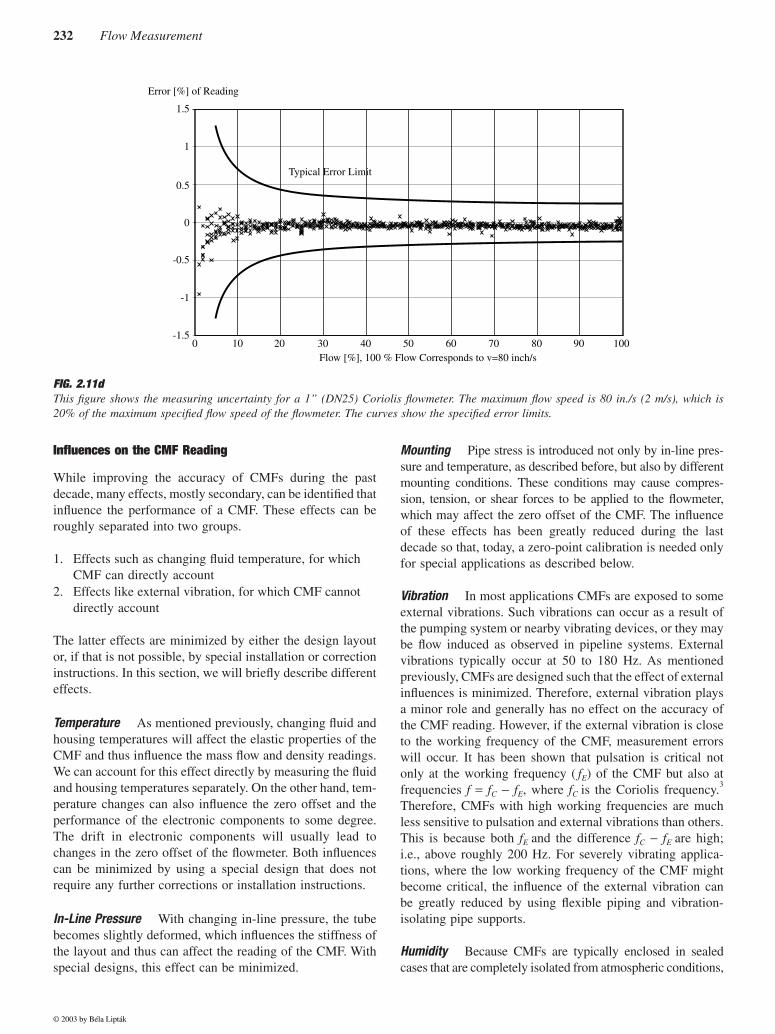
Figure 2.11d shows the excellent measuring accuracy and thelarge rangeability of CMF. During the 12-h test run, the zeropoint and the calibration factor remain stable and are wellwithin the specification of the instrument. Note that the read-ing remains accurate even at low flow rates, even below 1/100of the maximum flow rate specified for the CMF.
Pressure Drop
The pressure drop depends on tube design and mainlydepends on the length of the tube and its inner diameter. Forthe pressure drop of CMF with dual tubes, the design of theflow splitter is also important. The lowest pressure dropoccurs with single straight-tube flowmeters, where the innerdiameter of the measuring tube is identical to that of theconnected process pipe. Typical pressure drops at the maxi-mum flow speeds specified by manufacturers are 7 to 20 PSIG(0.5 to 1.5 bar) referred to water. For the measurementsshown in Figure 2.11d, the pressure drop at 80 in./sec (2 m/s)is only 0.4 PSIG (30 mbar).
© 2003 by Béla Lipták
232 Flow Measurement
Influences on the CMF Reading
While improving the accuracy of CMFs during the pastdecade, many effects, mostly secondary, can be identified thatinfluence the performance of a CMF. These effects can beroughly separated into two groups.
1. Effects such as changing fluid temperature, for whichCMF can directly account
2. Effects like external vibration, for which CMF cannotdirectly account
The latter effects are minimized by either the design layoutor, if that is not possible, by special installation or correctioninstructions. In this section, we will briefly describe differenteffects.
Temperature As mentioned previously, changing fluid andhousing temperatures will affect the elastic properties of theCMF and thus influence the mass flow and density readings.We can account for this effect directly by measuring the fluidand housing temperatures separately. On the other hand, tem-perature changes can also influence the zero offset and theperformance of the electronic components to some degree.The drift in electronic components will usually lead tochanges in the zero offset of the flowmeter. Both influencescan be minimized by using a special design that does notrequire any further corrections or installation instructions.
In-Line Pressure With changing in-line pressure, the tubebecomes slightly deformed, which influences the stiffness ofthe layout and thus can affect the reading of the CMF. Withspecial designs, this effect can be minimized.
Mounting Pipe stress is introduced not only by in-line pres-sure and temperature, as described before, but also by differentmounting conditions. These conditions may cause compres-sion, tension, or shear forces to be applied to the flowmeter,which may affect the zero offset of the CMF. The influenceof these effects has been greatly reduced during the lastdecade so that, today, a zero-point calibration is needed onlyfor special applications as described below.
Vibration In most applications CMFs are exposed to someexternal vibrations. Such vibrations can occur as a result ofthe pumping system or nearby vibrating devices, or they maybe flow induced as observed in pipeline systems. Externalvibrations typically occur at 50 to 180 Hz. As mentionedpreviously, CMFs are designed such that the effect of externalinfluences is minimized. Therefore, external vibration playsa minor role and generally has no effect on the accuracy ofthe CMF reading. However, if the external vibration is closeto the working frequency of the CMF, measurement errorswill occur. It has been shown that pulsation is critical notonly at the working frequency ( fE) of the CMF but also atfrequencies f = fC − fE, where fC is the Coriolis frequency.3
Therefore, CMFs with high working frequencies are muchless sensitive to pulsation and external vibrations than others.This is because both fE and the difference fC − fE are high;i.e., above roughly 200 Hz. For severely vibrating applica-tions, where the low working frequency of the CMF mightbecome critical, the influence of the external vibration canbe greatly reduced by using flexible piping and vibration-isolating pipe supports.
Humidity Because CMFs are typically enclosed in sealedcases that are completely isolated from atmospheric conditions,
FIG. 2.11dThis figure shows the measuring uncertainty for a 1” (DN25) Coriolis flowmeter. The maximum flow speed is 80 in./s (2 m/s), which is20% of the maximum specified flow speed of the flowmeter. The curves show the specified error limits.
Flow [%], 100 % Flow Corresponds to v=80 inch/s
Typical Error Limit
Error [%] of Reading
0 10 20 30 40 50 60 70 80 90 100
-0.5
-1
-1.5
0
0.5
1
1.5
© 2003 by Béla Lipták

2.11 Mass Flowmeters, Coriolis 233
external humidity has only a minor influence. Also, the flow-meter electronics are commonly enclosed in a housing thatprovides protection against external humidity. However, inCMFs with inadequate case seals or damaged housings,extremely humid environments can create condensation on theflow detector coils, which may lead to corrosion and compo-nent failure.
Fluid Velocity It is well known that the velocity of the fluidcan slightly influence the accuracy of the CMF reading.1 Thisis a minor effect, which is below the specified accuracy ofmost CMFs and does not necessarily require any correction.Nevertheless, given that the velocity of the fluid is known, aCMF can directly account for this effect.
Gas Measurements Only in recent years has it been shownthat the compressibility of gas can affect the accuracy of theCMF reading.4 Although this effect can be neglected for mostfluids, it becomes relevant for gases in which the speed ofsound is diminished. Knowledge about this effect allows usto correct the reading of CMF.
Two-Component Flow A CMF may be suitable for homo-geneous two-phase (solid/liquid) flows and for heterogeneousflows. Such applications include many food processes, sandin water, pulverized coal in nitrogen, water in oil, and manyothers. To measure two-phase fluids, single-tube meters maybe preferable.
Corrosion, Erosion Corrosion and erosion diminish thewall thickness and therefore change the stiffness of the tube,which can lead to faulty CMF readings. Since CMFs areavailable with different tube materials, corrosion can signif-icantly be reduced by choosing the appropriate material foreach application. To reduce erosion caused by highly abrasivemedia, it is necessary to keep the flow velocity low. Erosionalso depends on the design of CMF and is smallest in straight,single tubes.
Reynolds Number Although the accuracy of a CMF gen-erally does not depend on the flow profile, the sensitivitychanges slightly from laminar flow to eddy flow. Knowledgeof the Reynolds number allows us to determine the state ofthe flow regime and thus to account for it directly.
Installation
Some general recommendations for installations are applica-ble to all CMFs. The measuring tubes should remain full ofthe process fluid. Mixtures of gas and liquid should beavoided. For gas measurements, the tubes should be filledwith gas only, with no fluid droplets present.
The preferred installation orientation is vertical, with anupward flow direction. With this orientation, entrained sol-ids can sink downward, and gases can escape upward, whenthe medium is not flowing. This also allows the measuring
tubes to be completely drained and protects them from solidbuild up.
When measuring liquids, the CMF should not be installedat the highest point of the system, because gas may accumu-late in the flowmeter as shown in Figure 2.11e. Installationin a vertical pipeline directly upstream of a free pipe outletshould also be avoided.
With curved tubes, the CMF orientation should beadapted to type of fluid used. Figure 2.11f illustrates prob-lems with outgassing fluids and with fluids containing solidparticles.
Mechanical Installation Modern CMFs offer good balancein the vibration system and therefore have no specific instal-lation requirements. The CMF can be installed easily in apipeline. When heavy CMFs are used, mechanical supportof the pipeline has to be considered. Pipeline supports shouldnot be attached directly to the sensor, and the CMF shouldnot be used to support process piping directly.
FIG. 2.11eNot recommended mounting location of a CMF.
FIG. 2.11fOrientation of CMF with curved tubes; the orientation shown inthe left panel is not suitable for fluids with solids content; theorientation shown in the right panel is not suitable for outgassingfluids.
© 2003 by Béla Lipták
234 Flow Measurement
Zero-Point Adjustment (Static/Dynamic) After factory cal-ibration of a CMF, the calibration factor and the zero pointare stored in the electronics. CMFs that have good balance,and thus are decoupled from connected piping, are not affectedby the installation into the process piping. As a result, the zeropoint will not change, and no special zero-point adjustmentis necessary. Practical experience has shown that a zero-pointcalibration is required only in special cases; for example, toachieve the highest measuring accuracy possible in the pres-ence of very slow flow rates or in the case of extreme processconditions such as very high fluid temperatures.
Zero-point calibration is carried out using completelyfilled measuring tubes with no mass flow. During the zero-point adjustment, care has to be taken that no gas or solidsare present in the measuring tube. Keeping the in-line pres-sure high during the zero-point calibration reduces the riskof gas formation in the CMF and thus increases the accuracyof the zero-point calibration.
APPLICATIONS
CMFs are currently used in many areas, including chemical,petroleum, petrochemical, pharmaceutical, food and bever-age, and pulp and paper industries. Because of their versa-tility, CMFs are used for process control, batching, inventory,
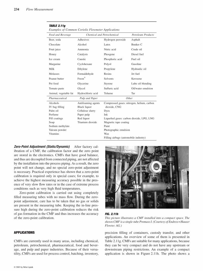
precision filling of containers, custody transfer, and otherapplications. An overview of some of them is presented inTable 2.11g. CMFs are suitable for many applications, becausethey can be very compact and do not have any upstream ordownstream piping restrictions. An example of a compactapplication is shown in Figure 2.11h. The photo shows a
TABLE 2.11gExamples of Common Coriolis Flowmeter Applications
Food and Beverage Chemical and Petrochemical Petroleum Products
Beer, soda
Chocolate
Fruit juice
Honey
Ice cream
Margarine
Milk
Molasses
Peanut butter
Pet food
Tomato paste
Animal, vegetable fat
Adhesives
Alcohol
Ammonia
Catalysts
Caustic
Cyclohexane
Ethylene
Formaldehyde
Freon
Glycerine
Glycol
Hydrochloric acid
Hydrogen peroxide
Latex
Nitric acid
Phosgene
Phosphoric acid
Polyol
Propylene
Resins
Solvents
Styrene
Sulfuric acid
Toluene
Asphalt
Bunker C
Crude oil
Diesel fuel
Fuel oil
Gasoline
Hydraulic oil
Jet fuel
Kerosene
Lube oil blending
Oil/water emulsion
Tar
Pharmaceutical Pulp and Paper Other
AlcoholsIV bag fillingPalm oilPerfumePill coatingsSoapSodium methylateTalcum powderVitamins
Antifoaming agentsBlack liquorCellulose slurryPaper pulpRed liquorTitanium dioxide
Compressed gases: nitrogen, helium, carbondioxide, CNG
DyesInkLiquefied gases: carbon dioxide, LPG, LNGMagnetic tape coatingPaintPhotographic emulsionWaxFilling airbags (automobile industry)
FIG. 2.11hThis picture illustrates a CMF installed into a compact space. Theshown CMF is a single-tube Promass I. (Courtesy of Endress+HauserFlowtec AG.)
© 2003 by Béla Lipták
2.11 Mass Flowmeters, Coriolis 235
single-tube CMF Promass I from Endress+Hauser FlowtecAG. Note that inlet and outlet parts are bent at a 90° angleand that the available room is very limited.
ADVANTAGES OF CMFs
1. One of most important advantages of CMFs is thatmass flow is measured directly. This can be per-formed with high accuracy, typically with 0.1% error.High accuracy is also maintained over wide rangesof temperatures (typically from −50 to +200°C) andin-line pressures. Furthermore, CMFs are extremelylinear over their entire flow range.
2. CMF rangeability is extremely high. Measurementscan still be performed at low flow rates, 100 timeslower than the maximum flow rate specified.
3. In addition to direct measurement of mass flow, tem-perature and density are measured directly. Knowl-edge about density allows us to convert mass flowdata into volume flow data.
4. The measuring principle is independent of the flowprofile of the fluid or gas. Therefore, no flow condi-tioner or special upstream or downstream pieces arerequired. A CMF can also be used with a pulsating flow.
5. The accuracy of a CMF is independent of fluid prop-erties such as viscosity or density. Therefore, a CMFcan measure all kinds of fluids, including Newtonianand non-Newtonian fluids, slurries, and gases.
6. CMFs do not have any moving parts that wear outand require replacement. This reduces the need forand the cost of maintenance.
7. Single-tube CMFs do not have internal obstructionsthat could be damaged or plugged.
8. CMFs are designed to measure forward and reverseflows with high accuracy.
9. Because CMFs are available based on different con-struction materials, they can be used for many dif-ferent applications, including corrosive fluids.
10. The design of CMFs allow them to operate with lowpower requirements.
LIMITATIONS OF CMFs
1. CMF prices are rather high as compared to other mea-suring device types. However, to measure mass flowwith a volumetric meter, it is often necessary to installan in-line densitometer, which brings the cost up toroughly the equivalent of a CMF alone.
2. There are no CMFs available for medium temperaturesabove 800°F (426°C).
3. CMFs cannot be used for liquids with any significantgas content. This effect can be reduced by increasingthe in-line pressure.
4. CMFs are not available for large pipelines; the largestCMF has a maximum flow rate of 63,000 lb/min(28,300 kg/min) using flanges with 10-in. (25-cm)diameters. To measure higher flow rates, two or moreCMFs must be mounted in parallel.
5. CMFs are not suitable for gas applications with lowin-line pressure, since low-pressure gases have lowdensities. To generate enough mass flow to provide asufficient Coriolis signal, the velocity of the gas mustbe quite high. This may lead to a large pressure dropacross the meter.
References
1. Païdoussis, M. P. and Li, G. X., Pipe conveying fluid: a model dynamicproblem, J. Fluids Struct., 7, 137–204, 1993.
2. Raszillier, H. and Durst, F., Coriolis effect in mass flow metering, Arch.Appl. Mech., 61, 192–214, 1991.
3. Koudal, O. et al., High frequency Coriolis meter performance underpulsating flow, in Proc. FLOMEKO 1998, 9th International Conferenceon Flow Measurement, Lund, Sweden, 239–242, 1998.
4. Anklin, M. et al., Effect of finite medium speed of sound on Coriolismass flowmeters, in Proc. FLOMEKO 2000 10th International Con-ference on Flow Measurement, Salvador, Brazil, 2000.
Bibliography
Adiletta, G. et al., Twin rigid straight pipe Coriolis mass flowmeter, Mea-surement, 11, 289–308, 1993.
Babb, M., New Coriolis meter cuts pressure drop in half, Control Eng.,October 1991.
Baker, R. C., Flow Measurement Handbook, Cambridge University Press,UK, 2000.
Baker, R. C., Coriolis flowmeters: industrial practice and published infor-mation, Flow Meas. Instrum., 5(4), 229–246, 1994.
Birker, B., Theory, design and performance of the straight tube mass flow-meter, in Mass Flow Measurements Direct and Indirect, IBC TechnicalServices Ltd., London, 1989.
Blickley, G. J., Mass flow measurement aided by coriolis methods, ControlEng., April 1991.
Blumenthal, I., Improving productivity through mass flow measurement andcontrol, enhancing productivity, in Proc. Pacific Cascade Instrumen-tation 1984 Exhibition and Symposium, 163–168, 1984.
Bugher, G., Coriolis flowmeters, Meas. Control, September 1990.Cascetta, F. et al., Experimental intercomparison of Coriolis mass flowme-
ters, Trans. Inst. Meas. Control, 14, 99–107, 1992.Corser, G. A. and Hammond, G. C., A combined effects meter, InTech, April
1993.Cheesewright, R., Clark, C. and Bisset, D., The identification of external
factors which influence the calibration of Coriolis mass flowmeters,Flow Meas. Instrum., 11, 1–10, 2000.
Cheesewright, R., Clark, C. and Bisset, D., The effect of flow pulsations onCoriolis mass flow meters, J. Fluids Struct., 1025–1039, 1998.
Cox, B. M. and Gonzales, F. A., Coriolis mass flow rate, U.S. Patent,4127028, 1978.
Drahm, W., New single straight tube Coriolis mass flowmeter without instal-lation restrictions, in Proc. FLOMEKO1998 9th International Confer-ence on Flow Measurement, Lund, Sweden, 243–248, 1998.
Durst, F. and Raszillier, H., Flow in a rotation straight pipe, with view onCoriolis mass flow meters, J. Fluids Eng., Trans. ASME, 112, 149–154,1990.
© 2003 by Béla Lipták
236 Flow Measurement
Eide, J. M. and Gwaspari, S. C., Comparison Test and Calibration of CoriolisMeters, North Sea Flow Measurement Workshop, Peebles, Scotland,1996.
Ginesi, D. and Annarummo, C., Application and installation guidelines forvolumetric and mass flowmeters, ISA Trans., 33(1), 61–72, 1994.
Grini, P. G., Maehlum, H. S. and Brendeng, E., In situ calibration of Coriolisflowmeters for high-pressure gas flow calibration, J. Meas. Instrum., 5,285–288, 1994.
Hemp, J., A theoretical investigation into the feasibility of Coriolis mass flow-meters for low density fluids, in Proc. FLOMEKO 1996 8th InternationalConference on Flow Measurement, Beijing, China, 265–270, 1996.
Hemp, J., The weight vector theory of Coriolis mass flowmeters, Flow Meas.Instrum., 5(4), 247–253, 1994.
Henry, M., On-line compensation in a digital Coriolis mass flow meter, FlowMeas. Instrum., 12, 147–161, 2001.
Kalotay, P., On-line viscosity measurement using Coriolis mass flowmeters,Flow Meas. Instrum., 5, 303–308, 1994.
Keita, N. M., Behaviour of straight type Coriolis mass flowmeters in themetering of gas: theoretical predictions with experimental verifications,Flow Meas. Instrum., 5, 289–294, 1994.
Kolahi, K., Gast, Th. and Rock, H., Coriolis mass flow measurements ofgas under normal conditions, Flow Meas. Instrum., 5, 275–283, 1994.
Medlock, R. and Furness, R. A., Mass flow measurement—a state of the artreview, Meas. Control, 23, 100–112, 1990.
Menke, D., Use of Coriolis mass flowmeters in custody transfer, in Proc.FLOMEKO 1996 8th International Conference on Flow Measurement,Beijing, China, 232–237, 1996.
Nicholson, S., Coriolis mass flow measurement, in Proc. FLOMEKO 1994Conference on Flow Measurement in the Mid 90s, NEL, Scotland, 1994.
Pawlas, G. and Patten, T., Gas measurement using Coriolis mass flowmeters,ISA Advances in Instrumentation and Control: International Confer-ence and Exhibition, 50(3), 781–790, 1995.
Plache, K., Coriolis/gyroscopic flow meter, Mech. Eng., 36, 1979.Raszillier, H. and Durst, F., Coriolis effect in mass flow metering, Arch.
Appl. Mech., 61, 192–214, 1991.
Raszillier, H., Allenborn, N. and Durst, F., Effect of a concentrated mass onCoriolis flowmetering, Arch. Appl. Mech., 64(6), 373–382, 1994.
Rezende, V. A. and Apple, C., Coriolis Meters for LGP Custody Transferat Petrobras, North Sea Flow Measurement Workshop, Kristiansand,Norway, Paper 30, 1997.
Rieder, A. and Drahm, W., A new type of single straight tube Coriolis massflowmeter, in Proc. FLOMEKO 1996 8th International Conference onFlow Measurement, Beijing, China, 250–254, 1996.
Robinson, C., Obstructionless flowmeters: smooth sailing for some, roughpassage for others, InTech, 33(12), 33–36, 1986.
Schietinger, M., Mass flow vs. volumetric flow, Meas. Control, September1990.
Sipin, A. J., Mass Flow Metering Means, U. S. Patent 3329019, July 4, 1967.Smith, J. E., Method and Structure of Flow Measurement, U. S. Patent
4187721, Feb. 12, 1980.Spitzer, D. W., Flow Measurement, Practical Guides for Measurement and
Control, ISA, Research Triangle Park, NC, 1991.Sultan, G., Single straight tube Coriolis mass flowmeter, Flow Meas.
Instrum., 3, 241–246, 1992.Tokyokeiki, K. K., Straight tube type mass flowmeter, Patent Par. Applu.
Disclosure 137 818/82, Tokyo, Japan, Aug. 25, 1982.Vetter, G. and Notzon, S., Effect of pulsating flow on Coriolis mass flow-
meters, Flow Meas. Instrum., 5, 263–273, 1994.Watt, R. M., Modelling of Coriolis mass flowmeters using ANSYS, in Proc.
ANSYS User Conference, Pittsburgh, 1990.Withers, V. R., Strang, W., and Allnutt, G., Practical Application of Coriolis
Meters for Offshore Tanker Loading from the Harding Field, NorthSea Flow Measurement Workshop, East Kilbride, NEL, Scotland,1996.
Yamashita, Y., Development of Coriolis mass flowmeter with a single straighttube as flow tube, in Proc. FLOMEKO 1996 8th International Confer-ence on Flow Measurement, Beijing, China, 265–270, 1996.
Young, A., Coriolis Flowmeters for Accurate Measurement of Liquid Prop-erties, ISA Advances in Instrumentation and Control: InternationalConference and Exhibition, 45(4), 1891–1898, 1990.
© 2003 by Béla Lipták