22-1780-13 product data - trane · tems, designed to keep you ... roof curb utility extension kit...
TRANSCRIPT
© 2012 Trane Pub. No. 22-1780-13
Product Data4WCC3018 through 4WCC3060Single Packaged Convertible Heat Pump 13 SEER 1½ - 5 TonR-410A
22-1780-13
10/12

2
It's Hard to Stop a Trane.Single Packaged Electric Heat Pump SystemTrane offers a complete family of electric heat pump heating and cooling sys-tems, designed to keep you comfortable all year long, regardless of the weath-er, while keeping your operating costs as low as possible. A heat pump oper-ates efficiently as both an air conditioner and a heater. In the summer, the heat pump cools your home just like any other air conditioner by pulling the heat from the inside and releasing it outdoors. In the winter, it captures the heat that is always present in the outdoor air and transfers it indoors.
Introducing the new TRANE Single Packaged Electric Heat Pump System.
Single Packaged Electric Heat Pump Systems are easy and versatile to install. Because cooling and heating functions are all contained in a single cabinet, a Trane packaged heat pump system is easy to install and service. It can be flush mounted beside your home at ground level or placed on the roof for horizontal or downflow installation. When connected to an optional Trane thermo-stat control and air distribution ducts, you have a highly efficient, total home comfort system.
Single Packaged Electric Heat Pump Systems provide better performance. Our single packaged cooling/heating units offer cooling/heating efficiencies that are unmatched in the industry and provide you with a product far superior in performance than the competition.
Single Packaged Electric Heat Pump Systems are unmatched in quality and reliability. All major components on these products, including the com-pressor, have been designed and manu-factured for maximum service. Every Climatuff® compressor is designed and manufactured to exacting specifications. Each design is life tested in extreme en-vironments to ensure reliable and long lasting operation in normal applications. Each compressor has internal motor protection for added reliability.
3
Contents
Optional Equipment Listing 4
General Data 5
Heater Data 9
SPEK Data 10
Performance Data
Indoor Fan 13
Typical Wiring 17
Optional Equipment 22
Dimensional Data 27
Mechanical Specifications 33
4
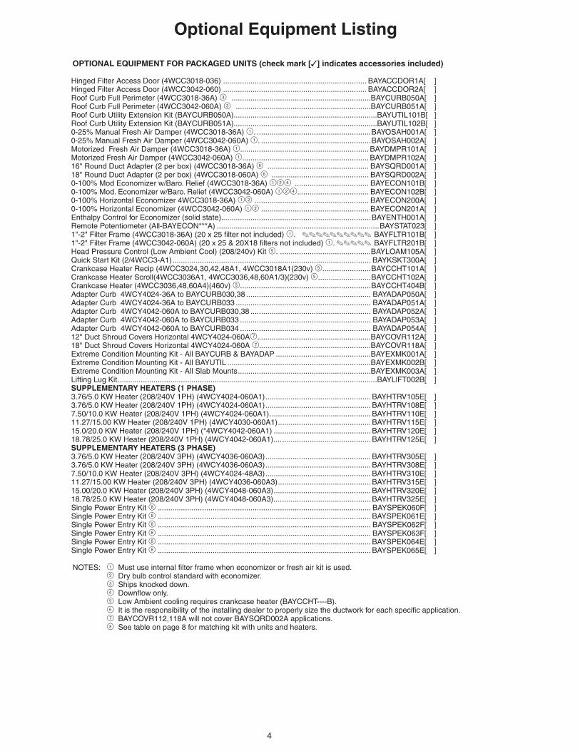
Optional Equipment Listing
OPTIONAL EQUIPMENT FOR PACKAGED UNITS (check mark [✓] indicates accessories included)
Hinged Filter Access Door (4WCC3018-036) .................................................................... BAYACCDOR1A[ ]Hinged Filter Access Door (4WCC3042-060) .................................................................... BAYACCDOR2A[ ]Roof Curb Full Perimeter (4WCC3018-36A) 3 ..................................................................BAYCURB050A[ ]Roof Curb Full Perimeter (4WCC3042-060A) 3 ................................................................BAYCURB051A[ ]Roof Curb Utility Extension Kit (BAYCURB050A)....................................................................BAYUTIL101B[ ]Roof Curb Utility Extension Kit (BAYCURB051A)....................................................................BAYUTIL102B[ ]0-25% Manual Fresh Air Damper (4WCC3018-36A) 1. ......................................................BAYOSAH001A[ ]0-25% Manual Fresh Air Damper (4WCC3042-060A) 1. ....................................................BAYOSAH002A[ ]Motorized Fresh Air Damper (4WCC3018-36A) 1. ............................................................ BAYDMPR101A[ ]Motorized Fresh Air Damper (4WCC3042-060A) 1. ........................................................... BAYDMPR102A[ ]16" Round Duct Adapter (2 per box) (4WCC3018-36A) 6 ................................................ BAYSQRD001A[ ]18" Round Duct Adapter (2 per box) (4WCC3018-060A) 6 .............................................. BAYSQRD002A[ ]0-100% Mod Economizer w/Baro. Relief (4WCC3018-36A) 124 ................................... BAYECON101B[ ]0-100% Mod. Economizer w/Baro. Relief (4WCC3042-060A) 124. ................................. BAYECON102B[ ]0-100% Horizontal Economizer 4WCC3018-36A) 12 . ..................................................... BAYECON200A[ ]0-100% Horizontal Economizer (4WCC3042-060A) 12 . .................................................. BAYECON201A[ ]Enthalpy Control for Economizer (solid state). ......................................................................BAYENTH001A[ ]Remote Potentiometer (All-BAYECON***A) .............................................................................BAYSTAT023[ ]1"-2" Filter Frame (4WCC3018-36A) (20 x 25 filter not included) 1. .......... BAYFLTR101B[ ]1"-2" Filter Frame (4WCC3042-060A) (20 x 25 & 20X18 filters not included) 1. ..... BAYFLTR201B[ ]Head Pressure Control (Low Ambient Cool) (208/240v) Kit 5. ...........................................BAYLOAM105A[ ] Quick Start Kit (2/4WCC3-A1) .............................................................................................. BAYKSKT300A[ ]Crankcase Heater Recip (4WCC3024,30,42,48A1, 4WCC3018A1(230v) 5. ......................BAYCCHT101A[ ]Crankcase Heater Scroll(4WCC3036A1, 4WCC3036,48,60A1/3)(230v) 5. ........................BAYCCHT102A[ ]Crankcase Heater (4WCC3036,48,60A4)(460v) 5. .............................................................BAYCCHT404B[ ]Adapter Curb 4WCY4024-36A to BAYCURB030,38 ........................................................... BAYADAP050A[ ] Adapter Curb 4WCY4024-36A to BAYCURB033 ................................................................ BAYADAP051A[ ] Adapter Curb 4WCY4042-060A to BAYCURB030,38 ......................................................... BAYADAP052A[ ] Adapter Curb 4WCY4042-060A to BAYCURB033 .............................................................. BAYADAP053A[ ] Adapter Curb 4WCY4042-060A to BAYCURB034 .............................................................. BAYADAP054A[ ]12" Duct Shroud Covers Horizontal 4WCY4024-060A7. .....................................................BAYCOVR112A[ ]18" Duct Shroud Covers Horizontal 4WCY4024-060A 7. ....................................................BAYCOVR118A[ ] Extreme Condition Mounting Kit - All BAYCURB & BAYADAP .............................................BAYEXMK001A[ ]Extreme Condition Mounting Kit - All BAYUTIL ....................................................................BAYEXMK002B[ ] Extreme Condition Mounting Kit - All Slab Mounts ...............................................................BAYEXMK003A[ ]Lifting Lug Kit ...........................................................................................................................BAYLlFT002B[ ]SUPPLEMENTARY HEATERS (1 PHASE)3.76/5.0 KW Heater (208/240V 1PH) (4WCY4024-060A1) .................................................. BAYHTRV105E[ ] 3.76/5.0 KW Heater (208/240V 1PH) (4WCY4024-060A1) .................................................. BAYHTRV108E[ ]7.50/10.0 KW Heater (208/240V 1PH) (4WCY4024-060A1) ................................................ BAYHTRV110E[ ]11.27/15.00 KW Heater (208/240V 1PH) (4WCY4030-060A1) ............................................ BAYHTRV115E[ ]15.0/20.0 KW Heater (208/240V 1PH) (*4WCY4042-060A1) .............................................. BAYHTRV120E[ ]18.78/25.0 KW Heater (208/240V 1PH) (4WCY4042-060A1).... .......................................... BAYHTRV125E[ ]SUPPLEMENTARY HEATERS (3 PHASE)3.76/5.0 KW Heater (208/240V 3PH) (4WCY4036-060A3) .................................................. BAYHTRV305E[ ] 3.76/5.0 KW Heater (208/240V 3PH) (4WCY4036-060A3) .................................................. BAYHTRV308E[ ] 7.50/10.0 KW Heater (208/240V 3PH) (4WCY4024-48A3) .................................................. BAYHTRV310E[ ]11.27/15.00 KW Heater (208/240V 3PH) (4WCY4036-060A3) ............................................ BAYHTRV315E[ ]15.00/20.0 KW Heater (208/240V 3PH) (4WCY4048-060A3) .............................................. BAYHTRV320E[ ]18.78/25.0 KW Heater (208/240V 3PH) (4WCY4048-060A3).... .......................................... BAYHTRV325E[ ]Single Power Entry Kit 8 . .................................................................................................... BAYSPEK060F[ ]Single Power Entry Kit 8 . .................................................................................................... BAYSPEK061E[ ]Single Power Entry Kit 8 . .................................................................................................... BAYSPEK062F[ ]Single Power Entry Kit 8 . .................................................................................................... BAYSPEK063F[ ]Single Power Entry Kit 8 . .................................................................................................... BAYSPEK064E[ ]Single Power Entry Kit 8 . .................................................................................................... BAYSPEK065E[ ]
NOTES: 1 Must use internal filter frame when economizer or fresh air kit is used. 2 Dry bulb control standard with economizer. 3 Ships knocked down. 4 Downflow only. 5 Low Ambient cooling requires crankcase heater (BAYCCHT----B). 6 It is the responsibility of the installing dealer to properly size the ductwork for each specific application. 7 BAYCOVR112,118A will not cover BAYSQRD002A applications. 8 See table on page 8 for matching kit with units and heaters.
5
MODELRATED Volts/PH/HzPerformance Cooling BTUHIndoor Airflow (CFM)Power Input (KW)EER/SEER (BTU/Watt-Hr.)Sound Power Rating [dB(A)]Performance Heating(High Temp.)BTUHPower Input (KW)(Low Temp.) BTUHPower Input (KW)HSPF (BTU / Watt-Hr.)POWER CONN.—V/Ph/HzMin. Brch. Cir. AmpacityFuse Size — Max. (amps)Fuse Size — Recmd. (amps)COMPRESSORVolts/Ph/HzR.L. Amps — L.R. AmpsOUTDOOR COIL — TYPERows/F.P.I.Face Area (sq.ft.)Tube Size (in.)Refrigerant ControlINDOOR COIL — TYPERows/F.P.I.Face Area (sq.ft.)Tube Size (in.)Refrigerant ControlDrain Conn. Size (in.)OUTDOOR FAN — TYPEDia. (in.)Drive/No. SpeedsCFM @ 0.0 in. w.g.Motor — HP/R.P.M.Volts/Ph/HzF.L. Amps/L.R. AmpsINDOOR FAN — TYPEDia x Width (in.)Drive/No. SpeedsCFM @ 0.0 in. w.g.Motor — HP/R.P.M.Volts/Ph/HzF.L. Amps/L.R. AmpsFILTER / FURNISHEDType RecommendedRecmd. Face Area (sq. ft.)REFRIGERANTCharge (lbs.)DIMENSIONSCrated (in.)WEIGHTShipping (lbs.) / Net (lbs.)
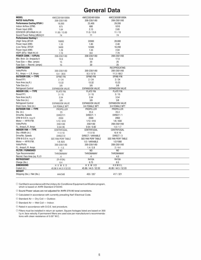
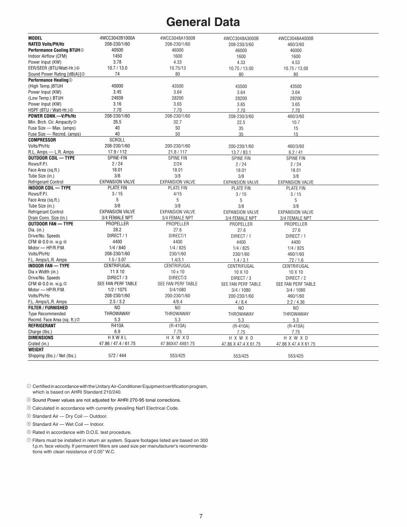
General Data
1 Certified in accordance with the Unitary Air-Conditioner Equipment certification program, which is based on AHRI Standard 210/240.
2 Sound Power values are not adjusted for AHRI 270-95 tonal corrections.
3 Calculated in accordance with currently prevailing Nat'l Electrical Code.
4 Standard Air — Dry Coil — Outdoor.
5 Standard Air — Wet Coil — Indoor.
6 Rated in accordance with D.O.E. test procedure.
7 Filters must be installed in return air system. Square footages listed are based on 300 f.p.m. face velocity. If permanent filters are used size per manufacturer's recommenda-tions with clean resistance of 0.05" W.C.
4WCC3018A1000A208-230/1/60
18,0006751.64
11.00 / 13.0074
168001.3394001.297.70
208-230/1/60 10.61515
200-230/1/60
6.4 - 38.6SPINE FIN
2 / 2413.32 3/8
EXPANSION VALVE PLATE FIN
3 / 15 3.54 3/8
EXPANSION VALVE 3/4 FEMALE NPT PROPELLER
23 DIRECT/1
2550 1/12 / 810 230/1/60 0.54/.95
CENTRIFUGAL 11 X 10
DIRECT/2 SEE FAN PERF TABLE
1/8 /825 200-230/1/60
1 - 1.5 NO
THROWAWAY4
(R-410A)6.4
H X W X D 45.86 X 44.5 X 52.03
444/348
4WCC3024B1000A208-230/1/60
23,4006802.13
11.0 / 13.071
220001.83
123001.538.0
208-230/1/6013.62020
200-230/1/608.3 / 57.8SPINE-FIN
2 / 2413.323/8
EXPANSION VALVEPLATE FIN
3 / 153.543/8
EXPANSION VALVE3/4 FEMALE NPT
PROPELLER23.4
DIRECT / 12500
1/12 / 810230/1/60
0.54 / 0.82CENTRIFUGAL
11 X 10DIRECT / VARIABLE
SEE FAN PERF TABLE1/2 / VARIABLE200-230/1/60
1.4 / 2.8NO
THROWAWAY4
R410A6.75
H X W X D45.86 / 44.5 / 52.03
453 / 357
4WCC3030B1000A208-230/1/60
29,20010102.65
11 / 1374
28,0002.40
16,2002.047.70
208-230/1/6017.02525
RECIPROCATING200-230/1/60
11.3 / 68.2SPINE-FIN
2 / 2413.233/8
EXPANSION VALVEPLATE FIN
3 / 153.543/8
EXPANSION VALVE3/4 FEMALE NPT
PROPELLER23.4
DIRECT / 12950
1/6 / 830208-230/1/60
1.0 / 1.7CENTRIFUGAL
10 X 10DIRECT / 3
SEE FAN PERF TABLE1/2/1080
208-230/1/602 / 4.4
NOTHROWAWAY
4.0R410A
6.5H X W X L
45.86 / 44.5 / 52.03
417 / 321

6
General DataMODELRATED Volts/PH/HzPerformance Cooling BTUHIndoor Airflow (CFM)Power Input (KW)EER/SEER (BTU/Watt-Hr.)Sound Power Rating [dB(A)]Performance Heating(High Temp.)BTUHPower Input (KW)(Low Temp.) BTUHPower Input (KW)HSPF (BTU / Watt-Hr.)POWER CONN.—V/Ph/HzMin. Brch. Cir. AmpacityFuse Size — Max. (amps)Fuse Size — Recmd. (amps)COMPRESSORVolts/Ph/HzR.L. Amps — L.R. AmpsOUTDOOR COIL — TYPERows/F.P.I.Face Area (sq.ft.)Tube Size (in.)Refrigerant ControlINDOOR COIL — TYPERows/F.P.I.Face Area (sq.ft.)Tube Size (in.)Refrigerant ControlDrain Conn. Size (in.)OUTDOOR FAN — TYPEDia. (in.)Drive/No. SpeedsCFM @ 0.0 in. w.g.Motor — HP/R.P.M.Volts/Ph/HzF.L. Amps/L.R. AmpsINDOOR FAN — TYPEDia x Width (in.)Drive/No. SpeedsCFM @ 0.0 in. w.g.Motor — HP/R.P.M.Volts/Ph/HzF.L. Amps/L.R. AmpsFILTER / FURNISHEDType RecommendedRecmd. Face Area (sq. ft.)REFRIGERANTCharge (lbs.)DIMENSIONSCrated (in.)WEIGHTShipping (lbs.) / Net (lbs.)
1 Certified in accordance with the Unitary Air-Conditioner Equipment certification program, which is based on AHRI Standard 210/240.
2 Sound Power values are not adjusted for AHRI 270-95 tonal corrections.
3 Calculated in accordance with currently prevailing Nat'l Electrical Code.
4 Standard Air — Dry Coil — Outdoor.
5 Standard Air — Wet Coil — Indoor.
6 Rated in accordance with D.O.E. test procedure.
7 Filters must be installed in return air system. Square footages listed are based on 300 f.p.m. face velocity. If permanent filters are used size per manufacturer's recommenda-tions with clean resistance of 0.05" W.C.
4WCC3036A1000B208-230/1/60
3500012003.18
11 / 1375
332002.81
199003.187.70
208-230/1/60 24.74040
208-230/1/60
16.7 - 79SPINE FIN
2 / 2413.32 3/8
EXPANSION VALVE PLATE FIN
4 / 15 3.54 3/8
EXPANSION VALVE 3/4 FEMALE NPT
PROPELLER 23
DIRECT / 1 3250
1/5 / 830 230/1/60 1.1 / 1.9
CENTRIFUGAL 10 X 10
DIRECT / 3 SEE FAN PERF TABLE
1/2 / 1075 200-230/1/60
2.7 /5.8 NO
THROWAWAY4.0
(R410A)7.25
H X W X D 45.86 X 44.5 X 52.03
468/372
4WCC3036A3000B208-230/3/60
3500012003.18
11.0 / 13.075
332002.81
199003.187.70
208-230/3/6016.82525
208-230/3/6010.4 / 73
SPINE-FIN2 / 2413.323/8
EXPANSION VALVEPLATE FIN
4 / 153.543/8
EXPANSION VALVE3/4 FEMALE NPT
PROPELLER23.0
DIRECT / 13250
1/5 / 830230/1/601.1 / 1.9
CENTRIFUGAL10 X 10
DIRECT / 3SEE FAN PERF TABLE
1/2 / 1075200-230/1/60
2.7 / 5.8NO
THROWAWAY4.0
R410A7.25
H X W X L45.86 / 44.5 / 52.03
468 / 372
4WCC3036A4000B460/3/60
3500012003.18
11 / 1375
332002.81
199003.187.70
460/3/60 9.61515
460/3/60 5.8 - 38
SPINE FIN 2 / 2413.32 3/8
EXPANSION VALVE PLATE FIN
4 / 15 3.54 3/8
EXPANSION VALVE 3/4 FEMALE NPT PROPELLER
23 DIRECT / 1
3250 1/5 / 830 460/1/60 0.6 - 1.3
CENTRIFUGAL 10 X 10
DIRECT / 2 SEE FAN PERF TABLE
1/2 / 1075 460/1/60
1.70 / 3.12 NO
THROWAWAY4.0
(R-410A)7.25 lbs.
H X W X D 45.86 X 44.5 X 52.03
568/372
7
General DataMODELRATED Volts/PH/HzPerformance Cooling BTUHIndoor Airflow (CFM)Power Input (KW)EER/SEER (BTU/Watt-Hr.)Sound Power Rating [dB(A)]Performance Heating(High Temp.)BTUHPower Input (KW)(Low Temp.) BTUHPower Input (KW)HSPF (BTU / Watt-Hr.)POWER CONN.—V/Ph/HzMin. Brch. Cir. AmpacityFuse Size — Max. (amps)Fuse Size — Recmd. (amps)COMPRESSORVolts/Ph/HzR.L. Amps — L.R. AmpsOUTDOOR COIL — TYPERows/F.P.I.Face Area (sq.ft.)Tube Size (in.)Refrigerant ControlINDOOR COIL — TYPERows/F.P.I.Face Area (sq.ft.)Tube Size (in.)Refrigerant ControlDrain Conn. Size (in.)OUTDOOR FAN — TYPEDia. (in.)Drive/No. SpeedsCFM @ 0.0 in. w.g.Motor — HP/R.P.M.Volts/Ph/HzF.L. Amps/L.R. AmpsINDOOR FAN — TYPEDia x Width (in.)Drive/No. SpeedsCFM @ 0.0 in. w.g.Motor — HP/R.P.M.Volts/Ph/HzF.L. Amps/L.R. AmpsFILTER / FURNISHEDType RecommendedRecmd. Face Area (sq. ft.)REFRIGERANTCharge (lbs.)DIMENSIONSCrated (in.)WEIGHTShipping (lbs.) / Net (lbs.)
1 Certified in accordance with the Unitary Air-Conditioner Equipment certification program, which is based on AHRI Standard 210/240.
2 Sound Power values are not adjusted for AHRI 270-95 tonal corrections.
3 Calculated in accordance with currently prevailing Nat'l Electrical Code.
4 Standard Air — Dry Coil — Outdoor.
5 Standard Air — Wet Coil — Indoor.
6 Rated in accordance with D.O.E. test procedure.
7 Filters must be installed in return air system. Square footages listed are based on 300 f.p.m. face velocity. If permanent filters are used size per manufacturer's recommenda-tions with clean resistance of 0.05" W.C.
4WCC3042B1000A208-230/1/60
4050014503.78
10.7 / 13.074
400003.45
249393.167.70
208-230/1/6026.54040
SCROLL208-230/1/60
17.9 / 112SPINE-FIN
2 / 2418.013/8
EXPANSION VALVEPLATE FIN
3 / 155
3/8EXPANSION VALVE3/4 FEMALE NPT
PROPELLER28.2
DIRECT / 14400
1/4 / 840208-230/1/60
1.5 / 3.07CENTRIFUGAL
11 X 10DIRECT / 3
SEE FAN PERF TABLE1/2 / 1075
208-230/1/602.5 / 3.2
NOTHROWAWAY
5.3R410A
6.9H X W X L
47.86 / 47.4 / 61.75
572 / 444
4WCC3048A1000B208-230/1/60
4600016004.33
10.75/1380
435003.64
282003.657.70
208-230/1/6032.75050
200-230/1/6021.8 / 117SPINE FIN
2/2418.013/8
EXPANSION VALVEPLATE FIN
4/155
3/8EXPANSION VALVE3/4 FEMALE NPT
PROPELLER27.6
DIRECT/14400
1/4 / 825230/1/601.4/3.1
CENTRIFUGAL10 x 10
DIRECT/3SEE FAN PERF TABLE
3/4/1080200-230/1/60
4/8.4NO
THROWAWAY5.3
(R-410A)7.75
H X W X D47.86X47.4X61.75
553/425
4WCC3048A3000B208-230/3/60
4600016004.33
10.75 / 13.0080
435003.64
282003.657.70
208-230/3/60 22.53535
200-230/1/60
13.7 / 83.1SPINE FIN
2 / 2418.013/8
EXPANSION VALVE PLATE FIN
3 / 15 5
3/8 EXPANSION VALVE 3/4 FEMALE NPT
PROPELLER 27.6
DIRECT / 1 4400
1/4 / 825 230/1/60 1.4 / 3.1
CENTRIFUGAL 10 X 10
DIRECT / 3 SEE FAN PERF TABLE
3/4 / 1080 200-230/1/60
4 / 8.4 NO
THROWAWAY5.3
(R-410A)7.75
H X W X D 47.86 X 47.4 X 61.75
553/425
4WCC3048A4000B460/3/60
4600016004.53
10.75 / 13.0080
435003.64
282003.657.70
460/3/60 10.71515
460/3/60 6.2 / 41
SPINE FIN 2 / 2418.01 3/8
EXPANSION VALVE PLATE FIN
3 / 15 5
3/8 EXPANSION VALVE 3/4 FEMALE NPT
PROPELLER 27.6
DIRECT / 1 4400
1/4 / 825 460/1/60 .72 / 1.6
CENTRIFUGAL 10 X 10
DIRECT / 2SEE FAN PERF TABLE
3/4 / 1080 460/1/60 2.2 / 4.36
NO THROWAWAY
5.3(R-410A)
7.75 H X W X D
47.86 X 47.4 X 61.75
553/425
8
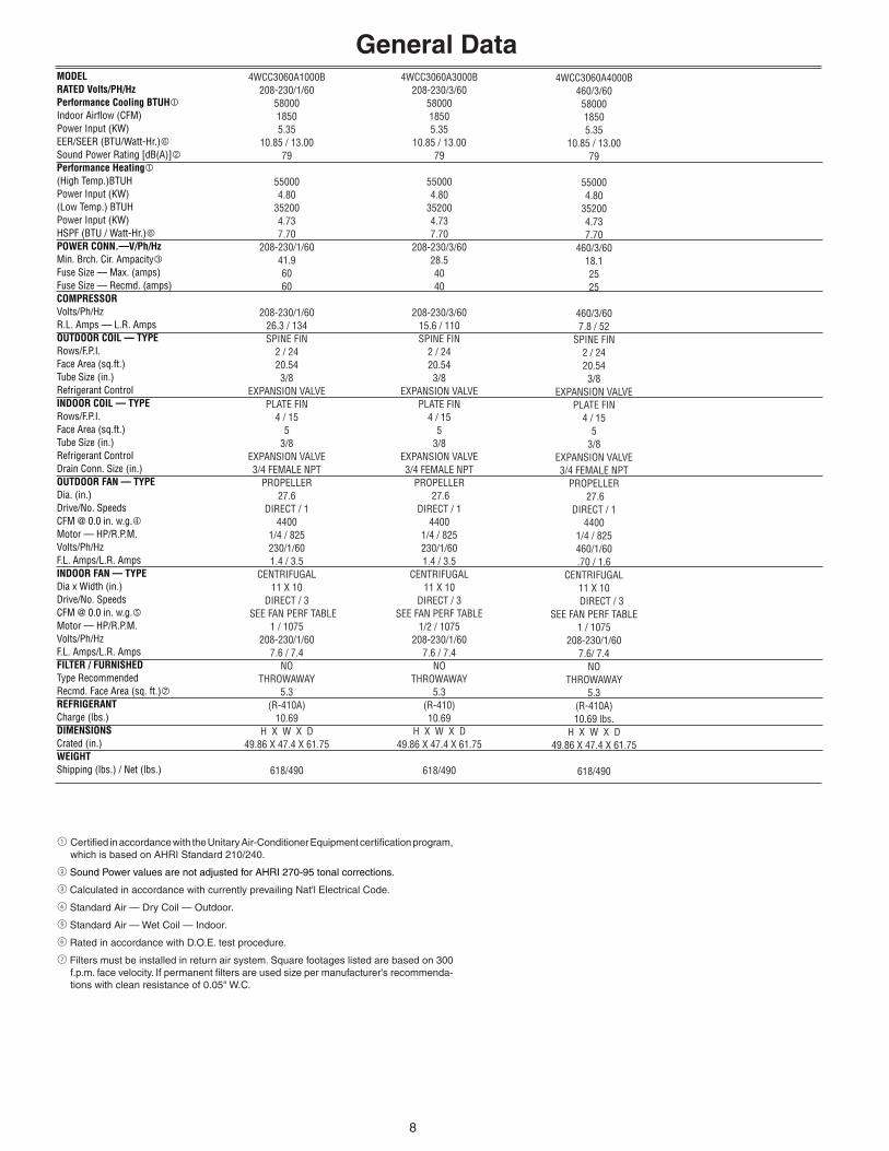
General DataMODELRATED Volts/PH/HzPerformance Cooling BTUHIndoor Airflow (CFM)Power Input (KW)EER/SEER (BTU/Watt-Hr.)Sound Power Rating [dB(A)]Performance Heating(High Temp.)BTUHPower Input (KW)(Low Temp.) BTUHPower Input (KW)HSPF (BTU / Watt-Hr.)POWER CONN.—V/Ph/HzMin. Brch. Cir. AmpacityFuse Size — Max. (amps)Fuse Size — Recmd. (amps)COMPRESSORVolts/Ph/HzR.L. Amps — L.R. AmpsOUTDOOR COIL — TYPERows/F.P.I.Face Area (sq.ft.)Tube Size (in.)Refrigerant ControlINDOOR COIL — TYPERows/F.P.I.Face Area (sq.ft.)Tube Size (in.)Refrigerant ControlDrain Conn. Size (in.)OUTDOOR FAN — TYPEDia. (in.)Drive/No. SpeedsCFM @ 0.0 in. w.g.Motor — HP/R.P.M.Volts/Ph/HzF.L. Amps/L.R. AmpsINDOOR FAN — TYPEDia x Width (in.)Drive/No. SpeedsCFM @ 0.0 in. w.g.Motor — HP/R.P.M.Volts/Ph/HzF.L. Amps/L.R. AmpsFILTER / FURNISHEDType RecommendedRecmd. Face Area (sq. ft.)REFRIGERANTCharge (lbs.)DIMENSIONSCrated (in.)WEIGHTShipping (lbs.) / Net (lbs.)
1 Certified in accordance with the Unitary Air-Conditioner Equipment certification program, which is based on AHRI Standard 210/240.
2 Sound Power values are not adjusted for AHRI 270-95 tonal corrections.
3 Calculated in accordance with currently prevailing Nat'l Electrical Code.
4 Standard Air — Dry Coil — Outdoor.
5 Standard Air — Wet Coil — Indoor.
6 Rated in accordance with D.O.E. test procedure.
7 Filters must be installed in return air system. Square footages listed are based on 300 f.p.m. face velocity. If permanent filters are used size per manufacturer's recommenda-tions with clean resistance of 0.05" W.C.
4WCC3060A1000B208-230/1/60
5800018505.35
10.85 / 13.0079
550004.80
352004.737.70
208-230/1/60 41.96060
208-230/1/60
26.3 / 134SPINE FIN
2 / 2420.54 3/8
EXPANSION VALVE PLATE FIN
4 / 15 5
3/8 EXPANSION VALVE 3/4 FEMALE NPT
PROPELLER 27.6
DIRECT / 1 4400
1/4 / 825 230/1/60 1.4 / 3.5
CENTRIFUGAL 11 X 10
DIRECT / 3 SEE FAN PERF TABLE
1 / 1075 208-230/1/60
7.6 / 7.4NO
THROWAWAY5.3
(R-410A)10.69
H X W X D 49.86 X 47.4 X 61.75
618/490
4WCC3060A3000B208-230/3/60
5800018505.35
10.85 / 13.0079
550004.80
352004.737.70
208-230/3/60 28.54040
208-230/3/60 15.6 / 110SPINE FIN
2 / 2420.54 3/8
EXPANSION VALVE PLATE FIN
4 / 15 5
3/8 EXPANSION VALVE 3/4 FEMALE NPT
PROPELLER 27.6
DIRECT / 1 4400
1/4 / 825 230/1/60 1.4 / 3.5
CENTRIFUGAL 11 X 10
DIRECT / 3SEE FAN PERF TABLE
1/2 / 1075 208-230/1/60
7.6 / 7.4 NO
THROWAWAY5.3
(R-410)10.69
H X W X D 49.86 X 47.4 X 61.75
618/490
4WCC3060A4000B460/3/60
5800018505.35
10.85 / 13.0079
550004.80
352004.737.70
460/3/60 18.12525
460/3/60 7.8 / 52
SPINE FIN 2 / 2420.54 3/8
EXPANSION VALVE PLATE FIN
4 / 15 5
3/8 EXPANSION VALVE 3/4 FEMALE NPT
PROPELLER 27.6
DIRECT / 1 4400
1/4 / 825 460/1/60 .70 / 1.6
CENTRIFUGAL 11 X 10
DIRECT / 3SEE FAN PERF TABLE
1 / 1075 208-230/1/60
7.6/ 7.4NO
THROWAWAY5.3
(R-410A)10.69 lbs.
H X W X D 49.86 X 47.4 X 61.75
618/490
9
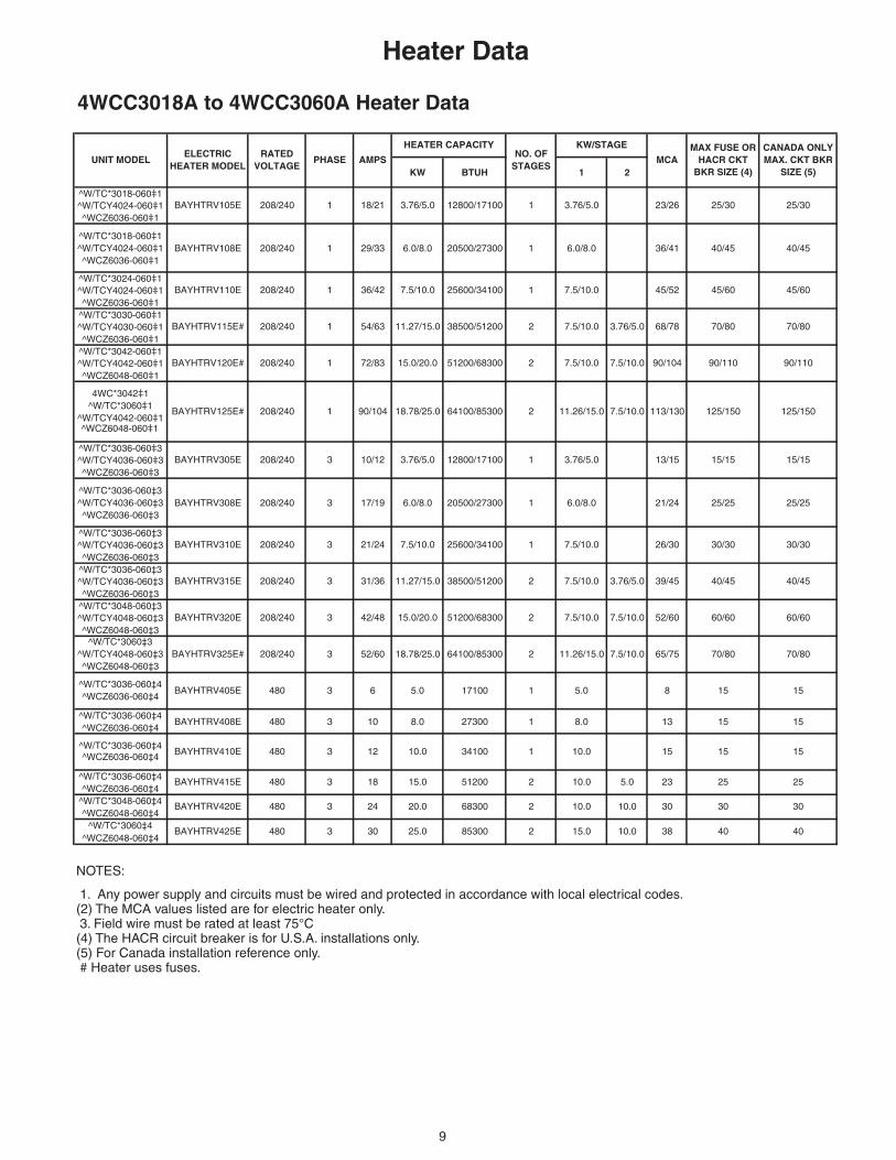
Heater Data
NOTES:
1. Any power supply and circuits must be wired and protected in accordance with local electrical codes. (2) The MCA values listed are for electric heater only. 3. Field wire must be rated at least 75°C (4) The HACR circuit breaker is for U.S.A. installations only. (5) For Canada installation reference only. # Heater uses fuses.
4WCC3018A to 4WCC3060A Heater Data
KW BTUH 1 2
^W/TC*3018-060‡1^W/TCY4024-060‡1^WCZ6036-060‡1
^W/TC*3018-060‡1^W/TCY4024-060‡1^WCZ6036-060‡1
BAYHTRV108E 208/240 1 29/33 6.0/8.0 20500/27300 1 6.0/8.0 36/41 40/45 40/45
^W/TC*3024-060‡1^W/TCY4024-060‡1^WCZ6036-060‡1
^W/TC*3030-060‡1^W/TCY4030-060‡1^WCZ6036-060‡1
^W/TC*3042-060‡1^W/TCY4042-060‡1^WCZ6048-060‡1
4WC*3042‡1^W/TC*3060‡1
^W/TCY4042-060‡1^WCZ6048-060‡1
^W/TC*3036-060‡3^W/TCY4036-060‡3^WCZ6036-060‡3
^W/TC*3036-060‡3^W/TCY4036-060‡3^WCZ6036-060‡3
BAYHTRV308E 208/240 3 17/19 6.0/8.0 20500/27300 1 6.0/8.0 21/24 25/25 25/25
^W/TC*3036-060‡3^W/TCY4036-060‡3^WCZ6036-060‡3
^W/TC*3036-060‡3^W/TCY4036-060‡3^WCZ6036-060‡3
^W/TC*3048-060‡3^W/TCY4048-060‡3^WCZ6048-060‡3
^W/TC*3036-060‡4^WCZ6036-060‡4
BAYHTRV408E 480 3 10 8.0 27300 1 8.0 13 15 15
^WCZ6036-060‡4
^W/TC*3036-060‡4^WCZ6036-060‡4
^W/TC*3048-060‡4^WCZ6048-060‡4
^W/TC*3060‡4^WCZ6048-060‡4
7.5/10.0
40/45 40/45
208/240 3 42/48 15.0/20.0 51200/68300 2 7.5/10.0
45/60
208/240 1 54/63 11.27/15.0 38500/51200 2 7.5/10.0
1 36/42 7.5/10.0 25600/34100
^W/TC*3036-060‡4
BAYHTRV115E#
BAYHTRV110E
BAYHTRV120E#
BAYHTRV305E
BAYHTRV310E
BAYHTRV315E
BAYHTRV320E
BAYHTRV325E#
MAX FUSE OR HACR CKT
BKR SIZE (4)
CANADA ONLY MAX. CKT BKR
SIZE (5)MCA AMPS
NO. OF STAGES
KW/STAGEHEATER CAPACITY
PHASEELECTRIC
HEATER MODELRATED
VOLTAGEUNIT MODEL
3
3
3
BAYHTRV105E
480
208/240 3
208/240
480 24 20.0
90/104 18.78/25.0
3
480
31/36 11.27/15.0
68300
8530025.030
5120015.018
12 10.0 34100
2
2
2
1
10.0
38
30
235.010.0
10.0
10.0 040.51
25
30
40
25
30
15
52/60 60/60
65/75
8
15
08/072
15
5.0
1 10.0
11.26/15.0 7.5/10.0
2 7.5/10.0 3.76/5.0
7.5/10.0
39/45
26/30 30/30 30/30
10/12 3.76/5.0 12800/17100 1 3.76/5.0
21/24 7.5/10.0 25600/34100 1
90/110
3.76/5.0 68/78
64100/85300 2 11.26/15.0 7.5/10.0
70/80
113/130 125/150
7.5/10.0 90/104 90/110
3.76/5.0 12800/17100 1 3.76/5.0
1 7.5/10.0
25/3023/26
45/52 45/60
25/30
70/80
208/240 1 72/83 15.0/20.0 51200/68300 2 7.5/10.0
BAYHTRV420E
BAYHTRV425E
60/60
70/80
15 15BAYHTRV405E
BAYHTRV410E
480
480
208/240 1 18/21
BAYHTRV415E
208/240
208/240 3
208/240 3
3
^W/TC*3060‡3^W/TCY4048-060‡3^WCZ6048-060‡3
^W/TC*3036-060‡4^WCZ6036-060‡4
BAYHTRV125E#
38500/51200
171006 5.0
52/60 18.78/25.0 64100/85300
125/150
208/240 3 13/15 15/15 15/15
1
10
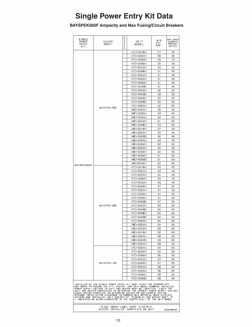
Single Power Entry Kit DataBAYSPEK060F Ampacity and Max Fusing/Circuit Breakers
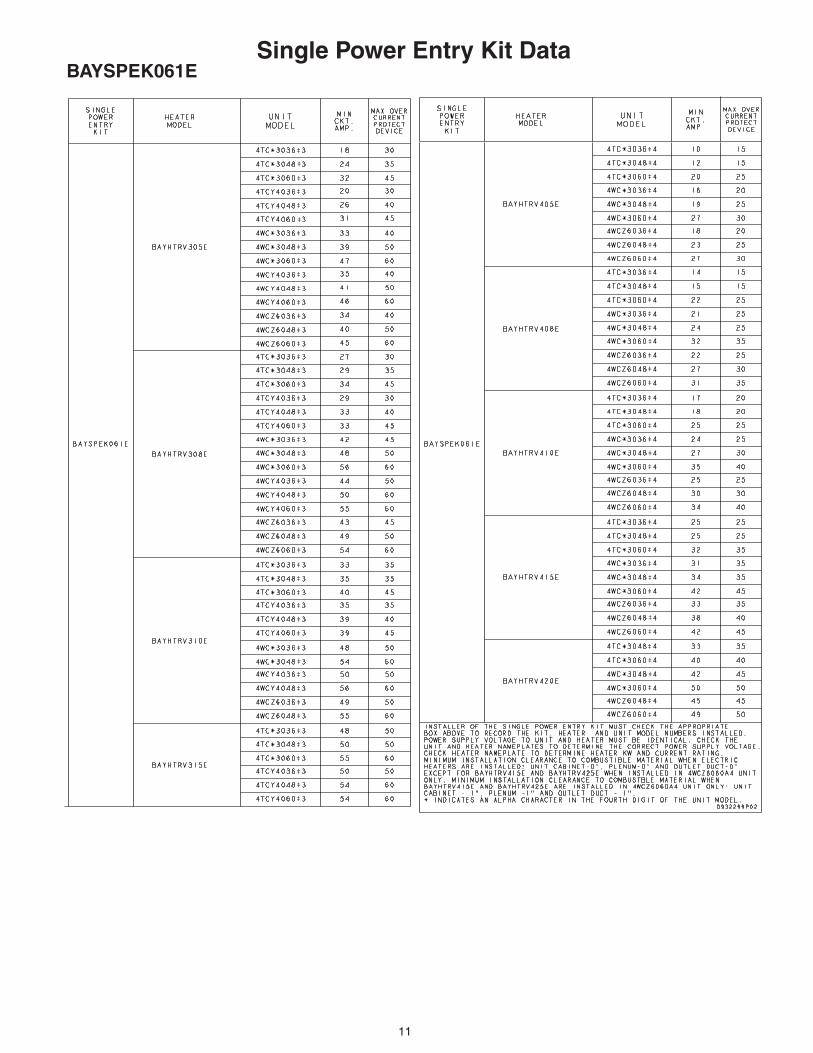
11
Single Power Entry Kit DataBAYSPEK061E
12
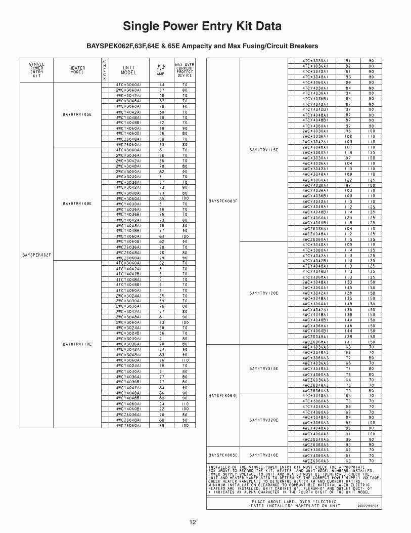
Single Power Entry Kit Data
BAYSPEK062F,63F,64E & 65E Ampacity and Max Fusing/Circuit Breakers
Horizontal Airflow
13
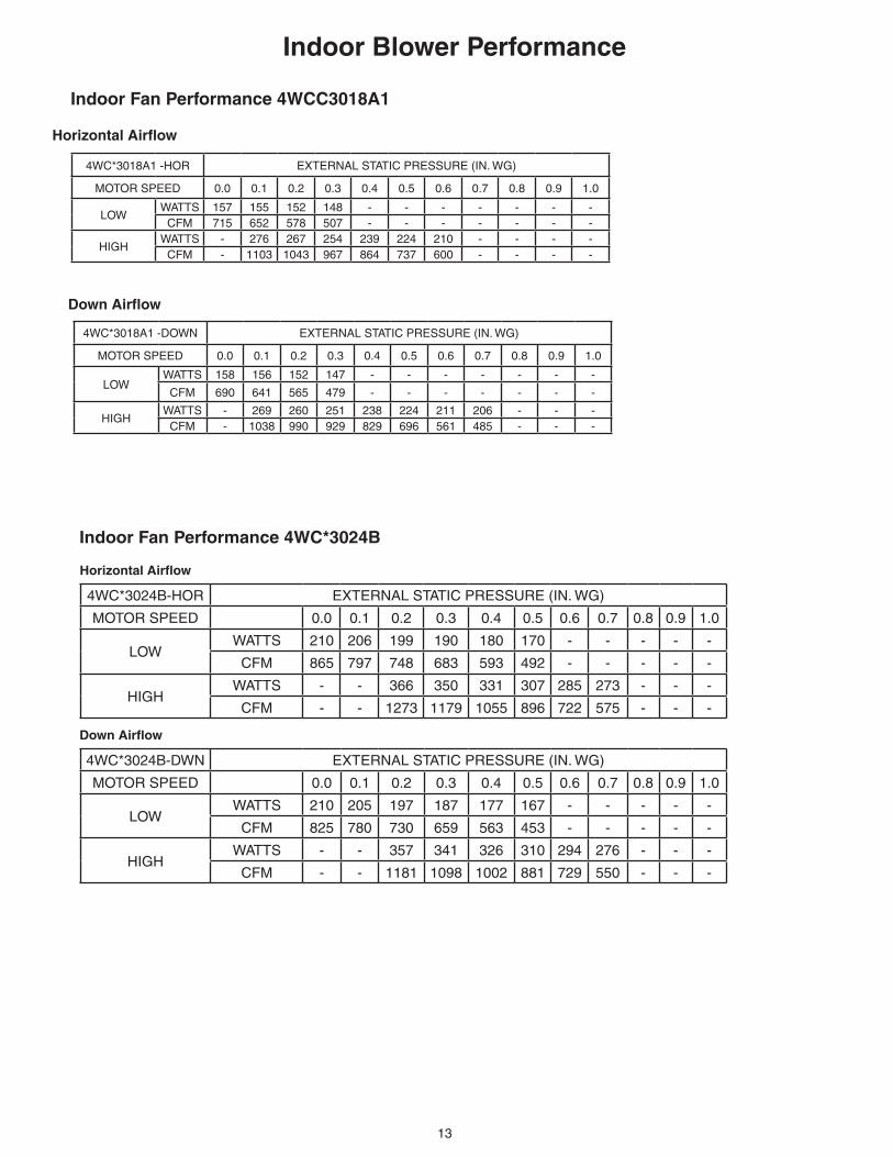
Indoor Blower Performance
Indoor Fan Performance 4WCC3018A1
Down Airflow
Horizontal Airflow
Indoor Fan Performance 4WC*3024B
Down Airflow
Horizontal Airflow
4WC*3024B-HOR EXTERNAL STATIC PRESSURE (IN. WG)
MOTOR SPEED 0.0 0.1 0.2 0.3 0.4 0.5 0.6 0.7 0.8 0.9 1.0
LOWWATTS 210 206 199 190 180 170 - - - - -
CFM 865 797 748 683 593 492 - - - - -
HIGHWATTS - - 366 350 331 307 285 273 - - -
CFM - - 1273 1179 1055 896 722 575 - - -
4WC*3024B-DWN EXTERNAL STATIC PRESSURE (IN. WG)
MOTOR SPEED 0.0 0.1 0.2 0.3 0.4 0.5 0.6 0.7 0.8 0.9 1.0
LOWWATTS 210 205 197 187 177 167 - - - - -
CFM 825 780 730 659 563 453 - - - - -
HIGHWATTS - - 357 341 326 310 294 276 - - -
CFM - - 1181 1098 1002 881 729 550 - - -
4WC*3018A1 -DOWN EXTERNAL STATIC PRESSURE (IN. WG)
MOTOR SPEED 0.0 0.1 0.2 0.3 0.4 0.5 0.6 0.7 0.8 0.9 1.0
LOWWATTS 158 156 152 147 - - - - - - -
CFM 690 641 565 479 - - - - - - -
HIGHWATTS - 269 260 251 238 224 211 206 - - -
CFM - 1038 990 929 829 696 561 485 - - -
4WC*3018A1 -HOR EXTERNAL STATIC PRESSURE (IN. WG)
MOTOR SPEED 0.0 0.1 0.2 0.3 0.4 0.5 0.6 0.7 0.8 0.9 1.0
LOWWATTS 157 155 152 148 - - - - - - -
CFM 715 652 578 507 - - - - - - -
HIGHWATTS - 276 267 254 239 224 210 - - - -
CFM - 1103 1043 967 864 737 600 - - - -

14
Indoor Blower Performance
Indoor Fan Performance 4WCC3036A
Down Airflow
Horizontal Airflow
Indoor Fan Performance 4WC*3030B
Down Airflow
Horizontal Airflow
4WC*3030B-HOR EXTERNAL STATIC PRESSURE (IN. WG)
MOTOR SPEED 0.0 0.1 0.2 0.3 0.4 0.5 0.6 0.7 0.8 0.9 1.0
LOWWATTS 275 267 263 258 248 - - - - - -
CFM 992 930 881 823 746 - - - - - -
MEDIUMWATTS 350 342 334 324 311 296 280 - - - -
CFM 1164 1120 1067 1002 921 826 720 - - - -
HIGHWATTS - - 572 558 542 523 501 473 - - -
CFM - - 1463 1390 1306 1210 1088 912 - - -
4WC*3030B-DOWN EXTERNAL STATIC PRESSURE (IN. WG)
MOTOR SPEED 0.0 0.1 0.2 0.3 0.4 0.5 0.6 0.7 0.8 0.9 1.0
LOWWATTS 275 270 264 256 245 - - - - - -
CFM 974 910 861 800 716 - - - - - -
MEDIUMWATTS 352 341 332 323 312 298 283 - - - -
CFM 1151 1096 1039 977 903 812 698 - - - -
HIGHWATTS - - 574 552 533 517 498 466 - - -
CFM - - 1434 1337 1243 1151 1036 842 - - -
4WC*3036A-HOR EXTERNAL STATIC PRESSURE (IN. WG)
MOTOR SPEED 0.0 0.1 0.2 0.3 0.4 0.5 0.6 0.7 0.8 0.9 1.0
LOWWATTS 351 342 335 327 314 - - - - - -
CFM 1154 1111 1067 1008 930 - - - - - -
MEDIUM WATTS 447 434 424 412 397 378 - - - - -
CFM 1348 1301 1251 1189 1110 1012 - - - - -
HIGHWATTS - - 675 658 640 619 594 563 - - -
CFM - - 1545 1490 1418 1311 1169 1012 - - -
4WC*3036A-DOWN EXTERNAL STATIC PRESSURE (IN. WG)
MOTOR SPEED 0.0 0.1 0.2 0.3 0.4 0.5 0.6 0.7 0.8 0.9 1.0
LOWWATTS 349 341 331 319 305 - - - - - -
CFM 1138 1083 1017 948 878 - - - - - -
MEDIUM WATTS 450 433 420 407 392 374 - - - - -
CFM 1325 1263 1200 1133 1058 970 - - - - -
HIGHWATTS - - 669 652 631 605 579 562 - - -
CFM - - 1517 1436 1336 1219 1095 980 - - -
15
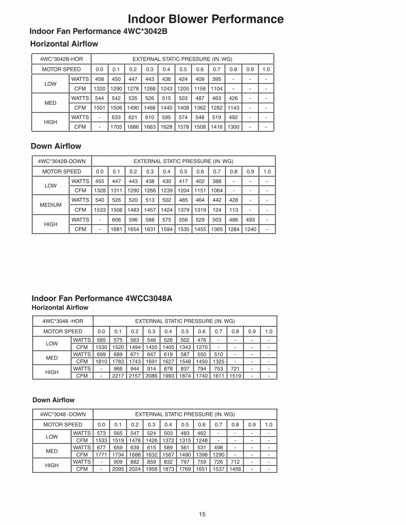
Indoor Fan Performance 4WCC3048A
Down Airflow
Horizontal Airflow
Indoor Blower PerformanceIndoor Fan Performance 4WC*3042B
Down Airflow
Horizontal Airflow
4WC*3042B-HOR EXTERNAL STATIC PRESSURE (IN. WG)
MOTOR SPEED 0.0 0.1 0.2 0.3 0.4 0.5 0.6 0.7 0.8 0.9 1.0
LOWWATTS 458 450 447 443 436 424 409 395 - - -
CFM 1320 1290 1278 1266 1243 1205 1156 1104 - - -
MEDWATTS 544 542 535 526 515 503 487 463 426 - -
CFM 1501 1506 1490 1466 1440 1408 1362 1282 1143 - -
HIGHWATTS - 633 621 610 595 574 548 519 492 - -
CFM - 1705 1686 1663 1628 1578 1508 1416 1300 - -
4WC*3042B-DOWN EXTERNAL STATIC PRESSURE (IN. WG)
MOTOR SPEED 0.0 0.1 0.2 0.3 0.4 0.5 0.6 0.7 0.8 0.9 1.0
LOWWATTS 455 447 443 438 430 417 402 388 - - -
CFM 1328 1311 1290 1266 1239 1204 1151 1064 - - -
MEDIUMWATTS 540 526 520 513 502 485 464 442 428 - -
CFM 1533 1506 1483 1457 1424 1379 1319 124 113 - -
HIGHWATTS - 606 596 588 575 556 529 503 486 493 -
CFM - 1681 1654 1631 1594 1535 1455 1365 1284 1240 -
4WC*3048 -HOR EXTERNAL STATIC PRESSURE (IN. WG)
MOTOR SPEED 0.0 0.1 0.2 0.3 0.4 0.5 0.6 0.7 0.8 0.9 1.0
LOWWATTS 585 575 563 546 526 502 476 - - - -
CFM 1530 1520 1494 1455 1405 1343 1270 - - - -
MEDWATTS 699 689 671 647 619 587 550 510 - - -
CFM 1810 1783 1743 1691 1627 1548 1450 1325 - - -
HIGHWATTS - 966 944 914 878 837 794 753 721 - -
CFM - 2217 2157 2086 1993 1874 1740 1611 1519 - -
4WC*3048 -DOWN EXTERNAL STATIC PRESSURE (IN. WG)
MOTOR SPEED 0.0 0.1 0.2 0.3 0.4 0.5 0.6 0.7 0.8 0.9 1.0
LOWWATTS 573 565 547 524 503 483 462 - - - -
CFM 1533 1519 1478 1426 1372 1315 1248 - - - -
MEDWATTS 677 659 639 615 589 561 531 498 - - -
CFM 1771 1734 1688 1632 1567 1490 1398 1290 - - -
HIGHWATTS - 909 882 859 832 797 759 726 712 - -
CFM - 2095 2024 1956 1873 1769 1651 1537 1456 - -
16
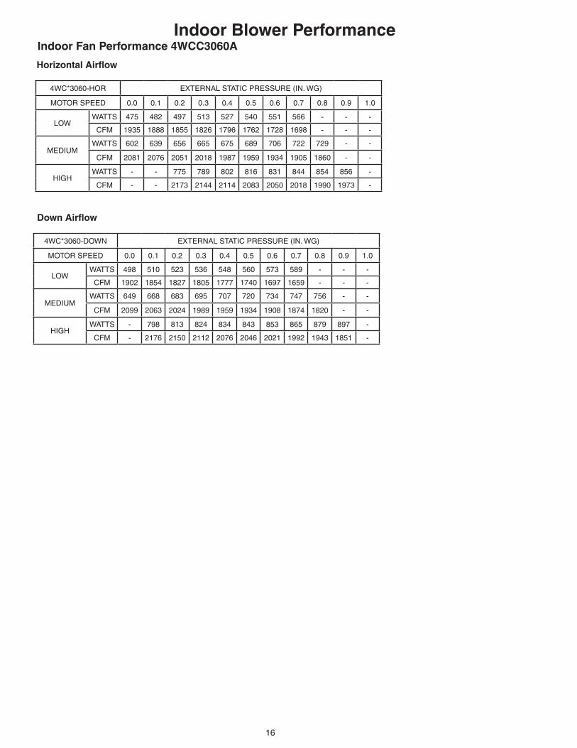
Indoor Fan Performance 4WCC3060A
Down Airflow
Horizontal Airflow
Indoor Blower Performance
4WC*3060-HOR EXTERNAL STATIC PRESSURE (IN. WG)
MOTOR SPEED 0.0 0.1 0.2 0.3 0.4 0.5 0.6 0.7 0.8 0.9 1.0
LOWWATTS 475 482 497 513 527 540 551 566 - - -
CFM 1935 1888 1855 1826 1796 1762 1728 1698 - - -
MEDIUMWATTS 602 639 656 665 675 689 706 722 729 - -
CFM 2081 2076 2051 2018 1987 1959 1934 1905 1860 - -
HIGHWATTS - - 775 789 802 816 831 844 854 856 -
CFM - - 2173 2144 2114 2083 2050 2018 1990 1973 -
4WC*3060-DOWN EXTERNAL STATIC PRESSURE (IN. WG)
MOTOR SPEED 0.0 0.1 0.2 0.3 0.4 0.5 0.6 0.7 0.8 0.9 1.0
LOWWATTS 498 510 523 536 548 560 573 589 - - -
CFM 1902 1854 1827 1805 1777 1740 1697 1659 - - -
MEDIUMWATTS 649 668 683 695 707 720 734 747 756 - -
CFM 2099 2063 2024 1989 1959 1934 1908 1874 1820 - -
HIGHWATTS - 798 813 824 834 843 853 865 879 897 -
CFM - 2176 2150 2112 2076 2046 2021 1992 1943 1851 -

17
COMMONFAN
COMPRSSOR1ST STAGE ELECTRIC HEAT
2ND STAGE ELECTRIC HEATSWITCHOVER VALVE
DEFROST CONTROL 'T' SIGNAL
24 VOLTS
BGY
W1W2OTR
UNIT LOW VOLTAGE AREA
TYPICAL THERMOSTAT
UNIT HEATER AREA
ELECTRICHEATERCONTROLBOX
POLARIZEDPLUG
UNIT CONTROL BOX
3 PHPOWERUNIT
NOTE 1,8
3 PHPOWERHEATER
1 PHPOWER
1 PHPOWER
UNIT CONTROLBOX
UNIT HEATER AREA
FACTORY PROVIDEDFIELD CONNECTEDWIRES
(BL)
(YL)
(GR)
(PR)
(OR)
(OR)
B
G
Y
W1W2
O
T
R
(BR)
(RD)
(GR)
(BL)
(WH)(WH)
(YL)
(OR)
1 PHPOWER
3 PHPOWER
GROUNDWIRE
SINGLE POWR ENTRY
W1W2
(WH)(WH)
W1
W2
(WH)
(WH)
HEATER SECOND STAGE AMBIENTTEMPERATURE LOCKOUTNOTE 7,8
UNIT LOWVOLTAGEAREA
OUTDOORTHERMOSTATACCESSORYBAYSTAT033A
NOTE 10
HEATER AMBIENTTEMPERATURE LOCKOUTNOTE 7,8
UNIT LOWVOLTAGEAREA
OUTDOORTHERMOSTATACCESSORYBAYSTAT033A
NOTE 10
TYPICAL THERMOSTATTYPICAL THERMOSTAT
TYPICAL 2-STAGE THERMOSTAT
UNIT LOWVOLTAGE AREA
UNIT LOWVOLTAGE AREA
TO COMPR.CONTACTOR
ELECTRICHEATERCONTROLBOX
HEATERFUSES
UNITFUSES
SPEACCESSORYKIT
TO ECONOMIZERFACTORY PROVIDEDFIELD INSTALLED WIRES
NOTE 9
(NOT APPLICABLE TO THE WCM---F MODELS)
FIG. 3 OUTDOOR THERMOSTAT ACCESSORY CONNECTIONS
FIG. 1 SINGLE POWER ENTRY ACCESSORY CONNECTIONS FIG. 2 ECONOMIZER ACCESSORYCONNECTIONS
GROUNDWIRE
SEE SPEK INSTALLER'S GUIDEFOR ALL OTHER EXAMPLES
NOTES:
1. FUSED DISCONNECT SIZE, POWER WIRING AND GROUNDING OF EQUIPMENT MUST COMPLY WITH CODES.
2. BE SURE POWER SUPPLY AGREES WITH EQUIP-MENT AND HEATER NAMEPLATE.
3. LOW VOLTAGE WIRING TO BE 18 AWG MINIMUM CONDUCTOR.
4. SEE HEATER NAMEPLATE FOR CURRENT RATING OF HEATER USED.
5. SEE UNIT AND HEATER DIAGRAM FOR ELECTRICAL CONNECTION DETAILS.
6. IF ELECTRIC HEATER ACCESSORY IS NOT INSTALLED OMIT THE ELECTRIC HEATER, AS-SOCIATED POWER WIRES AND THE ‘W’ AND ‘X2’ THERMOSTAT WIRES.
7. FIG. 3 DEMONSTRATES CONNECTION OF THE OUTDOOR THERMOSTAT ACCESSORY ONLY. FOR FURTHER UNIT CONNECTION DETAILS REFER TO THE OTHER FIGURES.
8. THE 41A(BR) WIRE IS FIRST STAGE ELECTRIC HEAT. IF THE ELECTRIC HEATER ACCESSORY HAS TWO HEATING STAGES THE 41C(BR) WIRE IS SECOND STAGE ELECTRIC HEAT.
9. WHEN THE BAYECON054A OR –055A ECONO-MIZER IS INSTALLED THE BAYRLAY003 RELAY ACCESSORY KIT IS REQUIRED TO INTERFACE THE ECONOMIZER TO THE HEAT PUMP FOR PROPER SYSTEM OPERATION. WHEN THE BAYECON054B OR –055B OR 073A ECONOMIZER IS INSTALLED, THE BAYRLAY004A RELAY ACCESSORY KIT IS RE-QUIRED TO INTERFACE THE ECONOMIZER TO THE HEAT PUMP FOR PROPER SYSTEM OPERATION.
10. THE BAYSTAT033A OUTDOOR THERMOSTAT AC-CESSORY KIT CONTAINS A THERMOSTAT AND A RELAY. THE RELAY IS NOT REQUIRED TO BE USED IN THIS APPLICATION.
Field Wiring Diagram
18
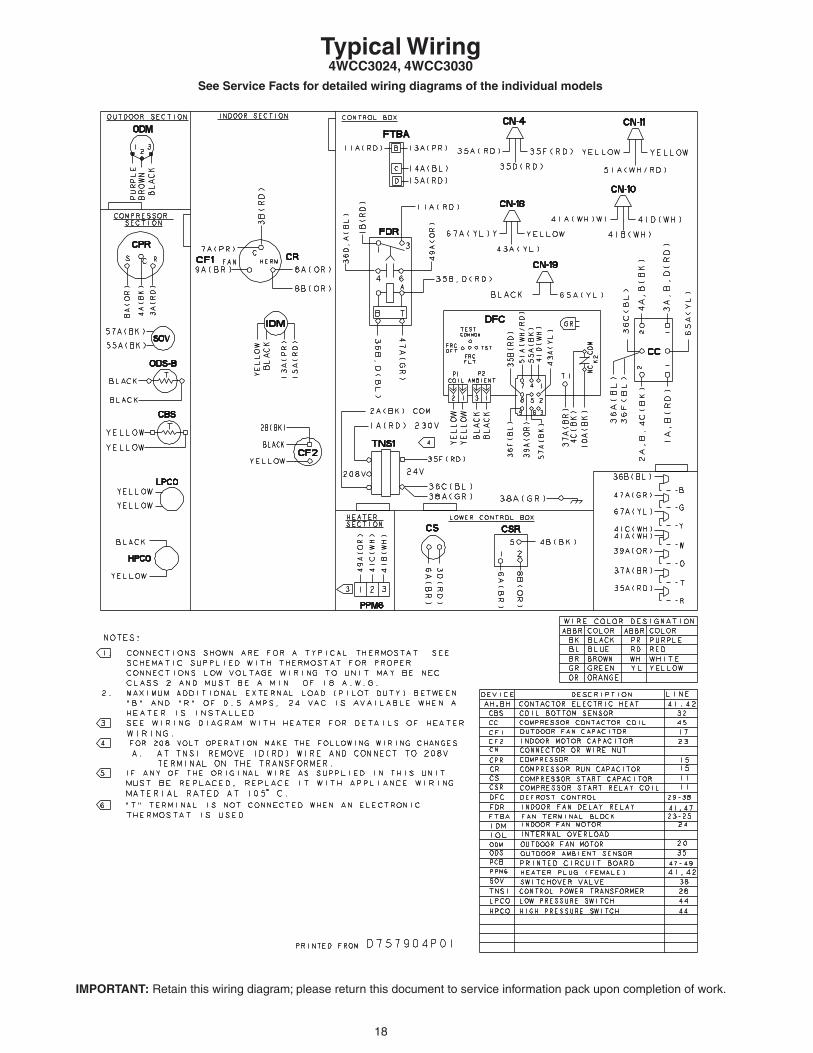
Typical Wiring4WCC3024, 4WCC3030
IMPORTANT: Retain this wiring diagram; please return this document to service information pack upon completion of work.
See Service Facts for detailed wiring diagrams of the individual models

19
WARNING: Do NOT connect 24 VAC to T1 terminal on DFC. ODS-B thermister WILL BE BLOWN.
IMPORTANT: Retain this wiring diagram; please return this document to service information pack upon completion of work.
Typical Wiring4WCC3024, 4WCC3030
See Service Facts for detailed wiring diagrams of the individual models
20
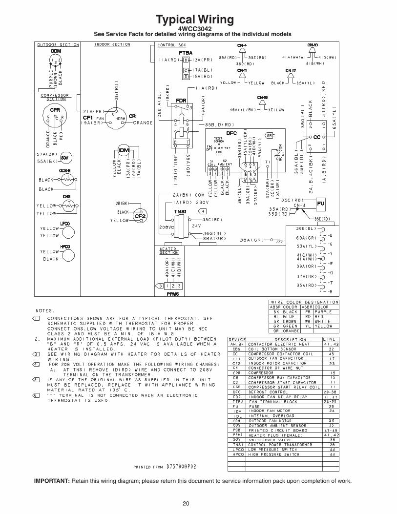
IMPORTANT: Retain this wiring diagram; please return this document to service information pack upon completion of work.
Typical Wiring4WCC3042
See Service Facts for detailed wiring diagrams of the individual models

21
WARNING: Do NOT connect 24 VAC to T1 terminal on DFC. ODS-B thermister WILL BE BLOWN.
IMPORTANT: Retain this wiring diagram; please return this document to service information pack upon completion of work.
Typical Wiring4WCC3042
See Service Facts for detailed wiring diagrams of the individual models
22
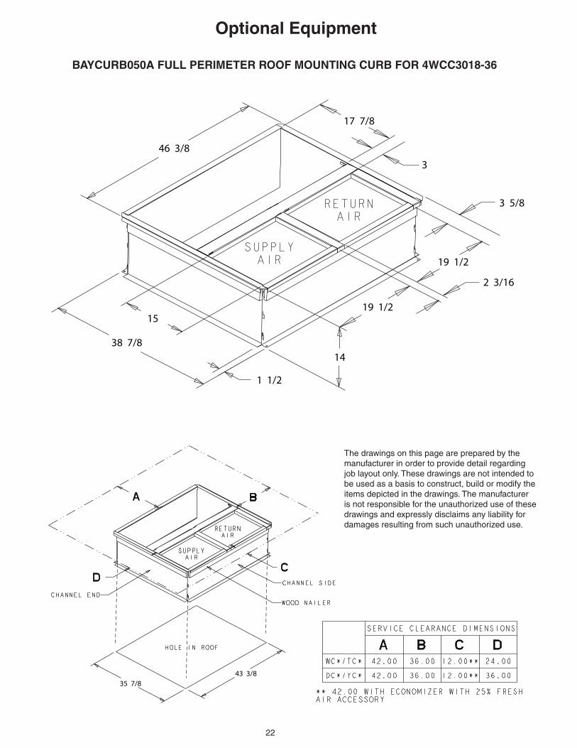
Optional Equipment
BAYCURB050A FULL PERIMETER ROOF MOUNTING CURB FOR 4WCC3018-36
46 3/8
17 7/8
3
3 5/8
19 1/2
2 3/16
19 1/2
14
1 1/2
38 7/8
15
35 7/843 3/8
The drawings on this page are prepared by the manufacturer in order to provide detail regarding job layout only. These drawings are not intended to be used as a basis to construct, build or modify the items depicted in the drawings. The manufacturer is not responsible for the unauthorized use of these drawings and expressly disclaims any liability for damages resulting from such unauthorized use.

23
Optional Equipment
BAYCURB051A Full Perimeter Roof Mounting Curb for 4WCC3042-60
56 1/8
15 7/8
3
10 7/819 1/2
4 3/4
19 1/2
14
41 7/8
20
1 1/2
38 7/8 53 1/8
The drawings on this page are prepared by the manufacturer in order to provide detail regarding job layout only. These drawings are not intended to be used as a basis to construct, build or modify the items depicted in the drawings. The manufacturer is not responsible for the unauthorized use of these drawings and expressly disclaims any liability for damages resulting from such unauthorized use.
24
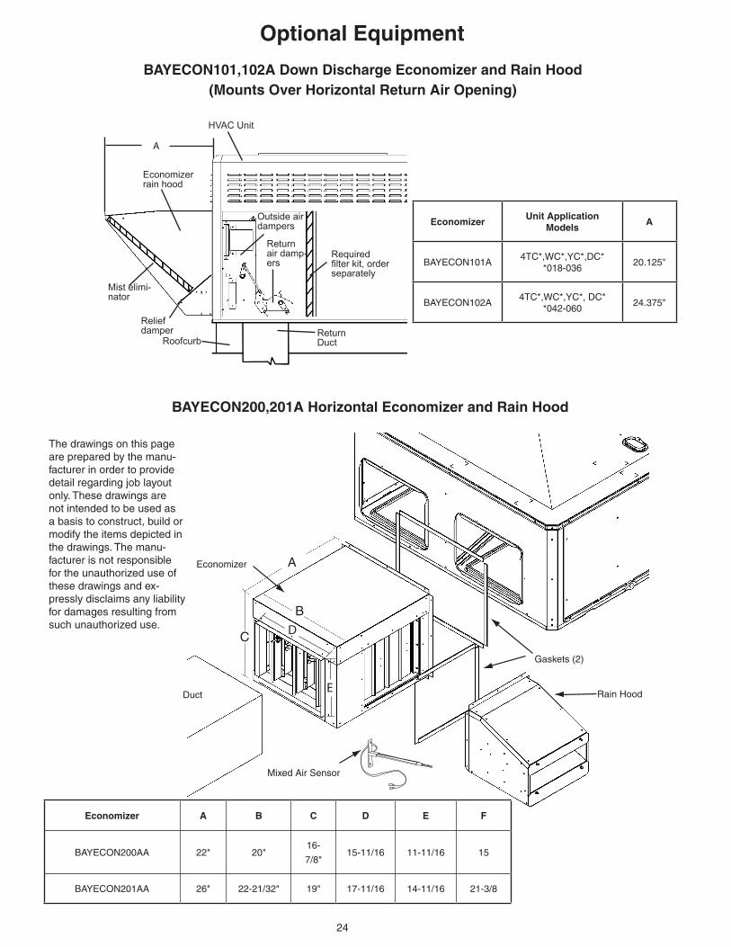
BAYECON101,102A Down Discharge Economizer and Rain Hood(Mounts Over Horizontal Return Air Opening)
A
B
C D
E
BAYECON200,201A Horizontal Economizer and Rain Hood
Return DuctRoofcurb
Relief damper
Mist elimi-nator
Economizer rain hood
HVAC Unit
Outside air dampers
Return air damp-ers
Required filter kit, order separately
A
Optional Equipment
Economizer
Gaskets (2)
Rain HoodDuct
The drawings on this page are prepared by the manu-facturer in order to provide detail regarding job layout only. These drawings are not intended to be used as a basis to construct, build or modify the items depicted in the drawings. The manu-facturer is not responsible for the unauthorized use of these drawings and ex-pressly disclaims any liability for damages resulting from such unauthorized use.
Mixed Air Sensor
EconomizerUnit Application
ModelsA
BAYECON101A4TC*,WC*,YC*,DC*
*018-03620.125"
BAYECON102A4TC*,WC*,YC*, DC*
*042-06024.375"
Economizer A B C D E F
BAYECON200AA 22" 20"16-
7/8"15-11/16 11-11/16 15
BAYECON201AA 26" 22-21/32" 19" 17-11/16 14-11/16 21-3/8
25
A
B
CD
FULLYOPEN
2/31/3
FULLYCLOSED
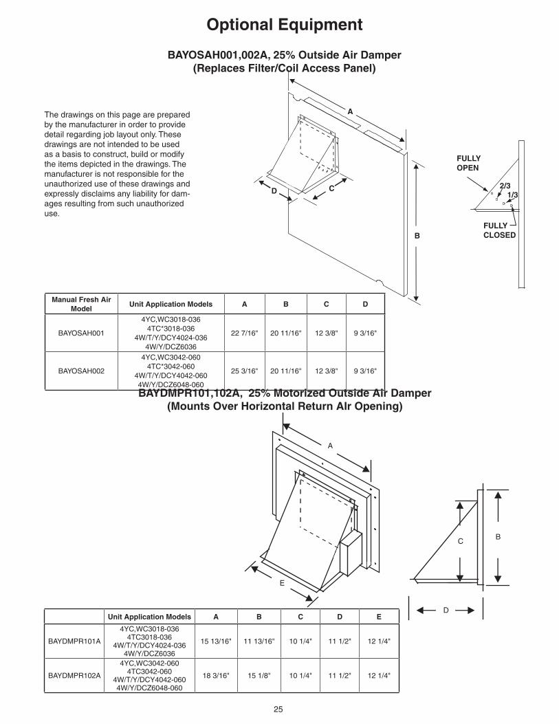
BAYDMPR101,102A, 25% Motorized Outside Air Damper(Mounts Over Horizontal Return AIr Opening)
BAYOSAH001,002A, 25% Outside Air Damper(Replaces Filter/Coil Access Panel)
Optional Equipment
The drawings on this page are prepared by the manufacturer in order to provide detail regarding job layout only. These drawings are not intended to be used as a basis to construct, build or modify the items depicted in the drawings. The manufacturer is not responsible for the unauthorized use of these drawings and expressly disclaims any liability for dam-ages resulting from such unauthorized use.
D
C B
A
E
Manual Fresh Air Model
Unit Application Models A B C D
BAYOSAH001
4YC,WC3018-0364TC*3018-036
4W/T/Y/DCY4024-0364W/Y/DCZ6036
22 7/16" 20 11/16" 12 3/8" 9 3/16"
BAYOSAH002
4YC,WC3042-0604TC*3042-060
4W/T/Y/DCY4042-0604W/Y/DCZ6048-060
25 3/16" 20 11/16" 12 3/8" 9 3/16"
Unit Application Models A B C D E
BAYDMPR101A
4YC,WC3018-0364TC3018-036
4W/T/Y/DCY4024-0364W/Y/DCZ6036
15 13/16" 11 13/16" 10 1/4" 11 1/2" 12 1/4"
BAYDMPR102A
4YC,WC3042-0604TC3042-060
4W/T/Y/DCY4042-0604W/Y/DCZ6048-060
18 3/16" 15 1/8" 10 1/4" 11 1/2" 12 1/4"

26
Optional Equipment
The drawings on this page are prepared by the manufacturer in order to provide detail regarding job layout only. These drawings are not intended to be used as a basis to construct, build or modify the items depicted in the drawings. The manufacturer is not respon-sible for the unauthorized use of these drawings and expressly disclaims any liability for damages resulting from such unauthorized use.
BAYFLTR101, 201B, 1" - 2" Filter Rack(Mounts in Filter/Coil Section)
BAYACCDOR1A & BAYACCDOR2A Hinged Filter Access DoorReplaces Filter/Coil Access Panel
Filter
27
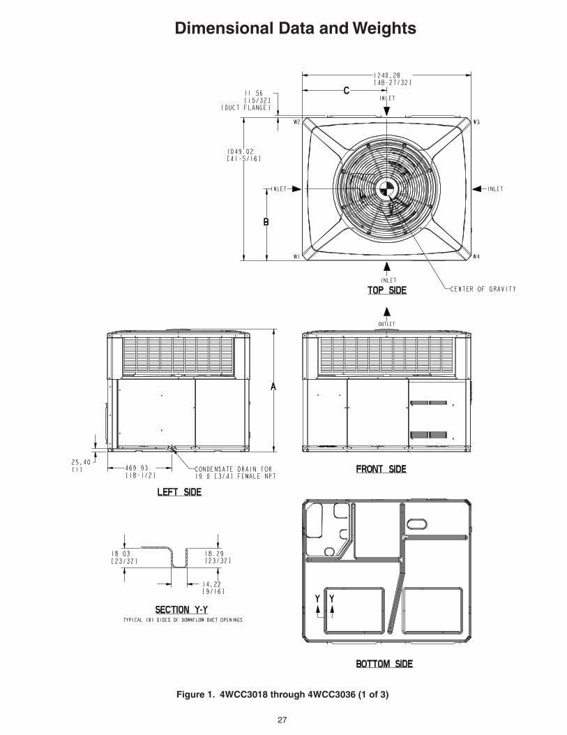
Dimensional Data and Weights
Figure 1. 4WCC3018 through 4WCC3036 (1 of 3)
28
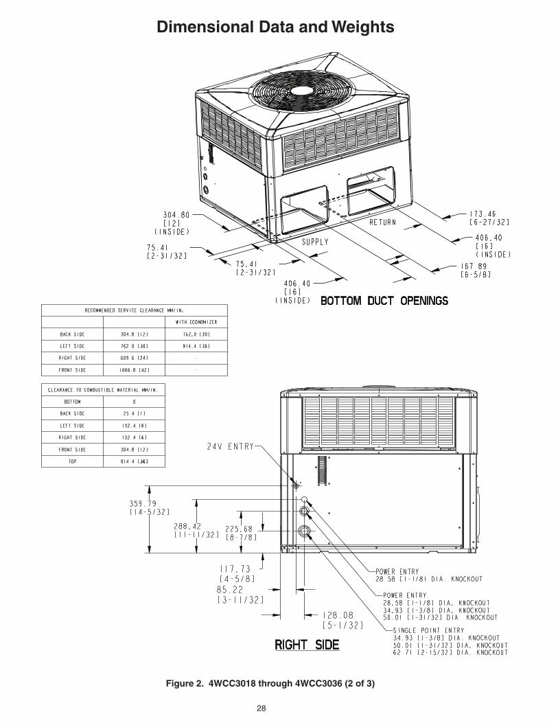
Dimensional Data and Weights
Figure 2. 4WCC3018 through 4WCC3036 (2 of 3)
29
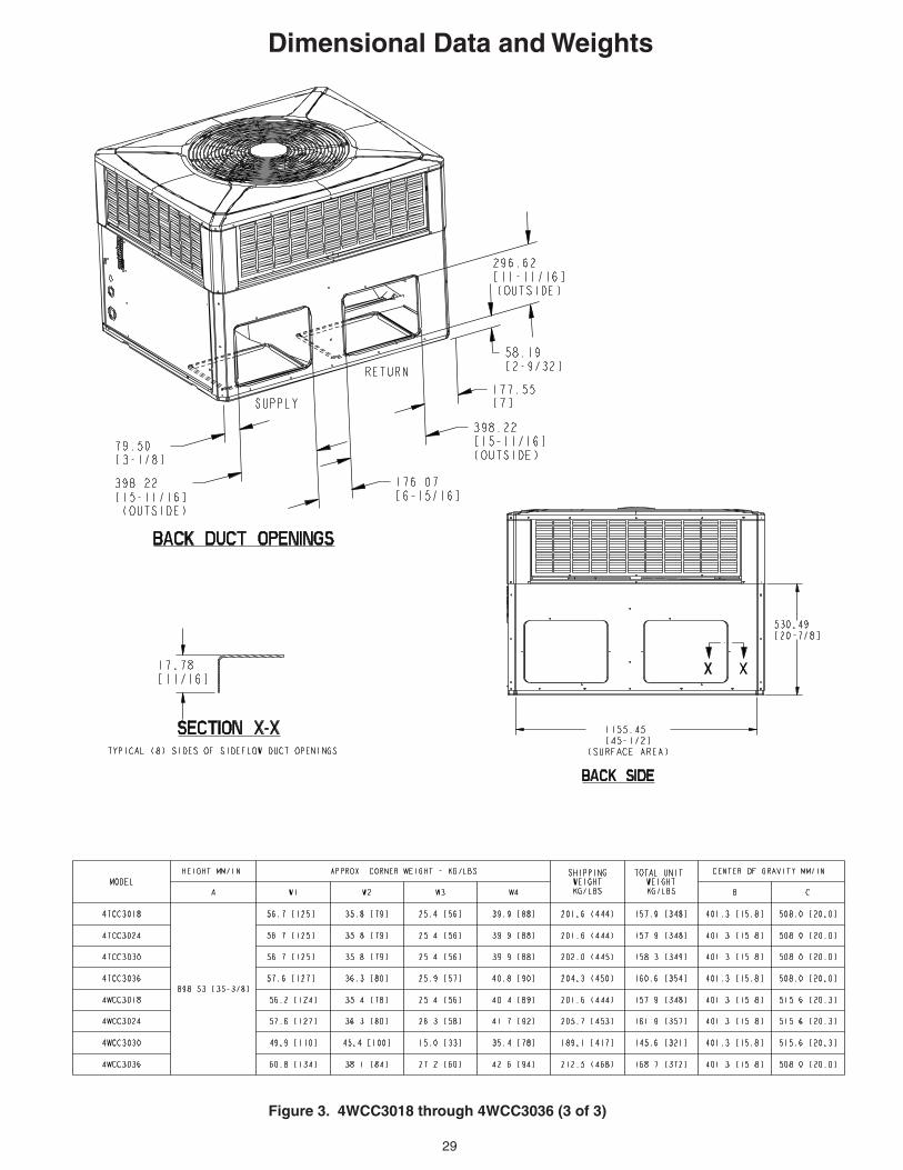
Dimensional Data and Weights
Figure 3. 4WCC3018 through 4WCC3036 (3 of 3)
30
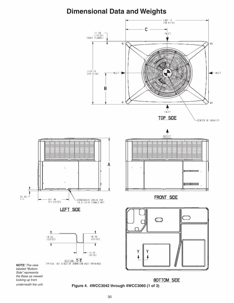
Figure 4. 4WCC3042 through 4WCC3060 (1 of 3)
Dimensional Data and Weights
NOTE: The view labeled “Bottom Side” represents the Base as viewed looking up from
underneath the unit.
31
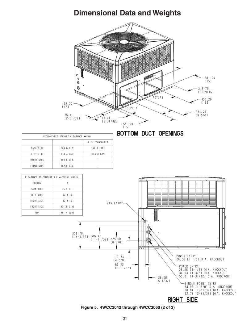
Dimensional Data and Weights
Figure 5. 4WCC3042 through 4WCC3060 (2 of 3)

32
Figure 6. 4WCC3042A through 4WCC3060A (3 of 3)
Dimensional Data and Weights

33
Mechanical Specifications
GeneralThe units shall be horizontal airflow as shipped and convertible to downflow. All units shall be factory assembled, piped, internally wired and fully charged with refrigerant. Units shall be certified to UL Standard 1995. All units shall be factory run tested to check cooling operation, fan and blower rotation, and control or TXV opera-tion. Units shall be designed to operate at ambient temperatures between 115°F and 55°F in cooling as manufactured. Cooling performance shall be rated in accordance with AHRI standards.
Unit CasingAll components shall be mounted in a weather-resistant steel cabinet with an enamel finish. Access panels shall be pro-vided for unit controls and indoor coil and fans. Indoor air section compartment shall be completely insulated with fireproof, permanent, odorless glass fiber material. Knockouts shall be provided for utility and control connections. Drain connections shall be provided to accommodate indoor water runoff.
CompressorThe compressor shall be hermetically sealed, high efficiency compressors. In-ternal overcurrent and over temperature protection, internal pressure relief shall be standard. Crankcase heaters shall be stan-dard on all models.
Refrigeration SystemAll units shall have TXV in cooling and TXV in heating. Service pressure tap ports, and a refrigerant line filter dryer shall be stan-dard.
Indoor CoilCoils shall be internally finned or smooth bore 3/8" copper tubes mechanically bonded to configured aluminum plate fin as standard. Evaporator coil leak and pressure tested to 200 psig; condenser coil tested to 450 psig.
Condenser Coil — The Spine Fin™ condenser coil shall be continuously wrapped, corrosion resistant all aluminum with minimum brazed joints. This coil is 3/8 inch O.D. seamless alumi-num tubing glued to a continuous alumi-num fin. Coils are lab tested to withstand 2,000 pounds of pressure per square inch. The outdoor coil provides low airflow resistance and efficient heat transfer. The coil is protected on all four sides by louvered panels.
Indoor Air Fan — Direct-drive, forward-curved, centrifugal wheel in a Composite Vortica® Blower housing. Motor shall have thermal overload protection. Perma-nently lubricated motor bearings. Motor/blower assembly isolated from unit with rubber mounts.
Condenser Fan — Direct-drive, draw thru propeller type. Weather-proofed perma-nent split capacitor fan motor shall have built-in thermal overload and permanently lubricated motor bearings.
System ControlsSystem controls include condenser fan, evaporator fan and compressor contactors.
AccessoriesRoof Curb — The roof curb shall be de-signed to mate with the unit and provide support and complete weathertight instal-lation when properly installed. Adhesive back polyurethane sealing strips shall be provided to ensure an airtight seal between supply and return openings of the curb and unit. The roof curb design allows field fabri-cated ductwork to be connected directly to the curb. Curb ships knocked down for field assembly, and includes factory-installed wood nailer strips.
Electric Heaters — Each heater assembly shall include power supply fusing if over 48 amps, automatic resetting limit switches and heat limiters for thermal protection. Heaters shall be provided with polarized plugs for quick connection to unit low volt-age wiring. Electric heat modules shall be UL listed.
Single Source Power Entry — This ac-cessory when used with electric heat accessory shall allow single source power connection to unit and heater combina-tion. Single source power entry kits shall have specific matching heater(s). Kit shall include high voltage terminal blocks, fuse blocks and fuses, cut-to-length in-terconnecting wiring, and junction box (if required) to provide power sources with fuse protection as required for both the unit and accessory heater. Kit compo-nents shall install within the unit cabinet in the heater access section. Single source branch power circuit shall be protected and wired in accordance with local codes.
Fully Modulating Economizer — This accessory shall be field installed and be composed of the following items: 0-100% fresh air damper, damper drive motor, fixed dry bulb enthalpy control, and low voltage wiring plug for electrical connections. Solid state enthalpy or differential enthalpy con-trol is optional. Economizer operations shall be controlled by the preset position of the enthalpy control. A barometic relief damper shall be standard with the econo-mizer and provide a pressure operated damper that shall be gravity closing and prohibit entrance of outside air on equip-ment “off” cycle. Economizer requires BAYRLAY004A relay kit to interface the economizer to the heat pump.
Manual Outside Air Dampers — Rain hood and screen shall be field installed. Suitable for up to 25% outside air.
Start Kit — Extra compressor starting ca-pacity for single phase equipment.
Control OptionsStandard Indoor Thermostats — Two stage heating/cooling or one stage heat-ing/cooling thermostats shall be available in either manual or automatic changeover.
Programmable Electronic Night Set-back Thermostat — Programmable electronic thermostat shall provide heat-ing setback and cooling setup with 7-day, programming capability. 1H/1C or 2H/2C models available.
Trane6200 Troup HighwayTyler, TX 75707-9010
The manufacturer has a policy of continuous product and product data improvement. It reserves the right to change design and speci-fication without notice.