25500643 rev. a2 0321 safety message to installers of
TRANSCRIPT

Safety Message to Installers of Siren Speakers
People’s lives depend on your proper installation and servicing of Federal Signal products. It is important to read and follow all instructions shipped with this product. Listed below are some other important safety instructions and precautions you should follow.
• To properly install or service this equipment, you must have a good understanding of automotive mechanical and electrical procedures and systems, along with proficiency in the installation and service of safety warning equipment. Always refer to the vehicle’s service manuals when performing equipment installations on a vehicle.
• To be an effective warning device, this product produces bright light that can be hazardous to your eyesight when viewed at a close range. Do not stare directly into this lighting product at a close range, or permanent damage to your eyesight may occur.
• Do not install the light system in an area that would block, impair, or blind the driver’s vision. Ensure that the light system is mounted in a position that is outside the driver’s field of vision so the driver can safely operate the vehicle.
• A light system is a high current system. For the system to function properly, a separate negative (–) connection and positive (+) connection must be made. All negative connections should be connected to the negative battery terminal, and a suitable fuse should be installed on the positive battery terminal connection as close to the battery as possible. Ensure that all wires and fuses are rated correctly to handle the device and system amperage requirements.
• Never attempt to install aftermarket equipment that connects to the vehicle wiring without reviewing a vehicle wiring diagram available from the vehicle manufacturer. Ensure that your installation will not affect vehicle operation or mandated safety functions or circuits. Always check the vehicle for proper operation after installation.
• The lighting system components, especially the outer housing, get hot during operation. Disconnect power to the system and allow the system to cool down before handling any components of the system.
• Do not mount a radio antenna within 18 inches (45.7 cm) of the lighting system. Placing the antenna too close to the lighting system could cause the lighting system to malfunction or be damaged by strong radio fields. Mounting the antenna too close to the lighting system may also cause the radio noise emitted from the lighting system to interfere with the reception of the radio transmitter and reduce radio reception.
• Do not attempt to wash any unsealed electrical device while it is connected to its power source.
• DO NOT connect this system to the vehicle battery until ALL other electrical connections are made, mounting of all components is complete, and you have verified that no shorts exist. If the wiring is shorted to the vehicle body or frame, high current conductors can cause hazardous sparks, resulting in electrical fires or flying molten metal.
• DO NOT install equipment or route wiring (or the plug-in cord) in the deployment path of an airbag.
MicroPulse® MPSxxU Manual
25500643 Rev. A2 0321

MicroPulse MPSxxU Manual
2MPSxxU Light Head
Federal Signal www.fedsig.com
• Before drilling into a vehicle structure, ensure that both sides of the surface are clear of anything that could be damaged. Remove all burrs from drilled holes. To prevent electrical shorts, grommet all drilled holes through which wiring passes. Ensure that the mounting screws do not cause electrical or mechanical damage to the vehicle.
• Because vehicle roof construction and driving conditions vary, do not drive a vehicle with a magnetically mounted warning light installed. The light could fly off the vehicle, causing injury or damage. Repair of damage incurred because of ignoring this warning shall be the sole responsibility of the user.
• Locate the light system controls so the VEHICLE and CONTROLS can be operated safely under all driving conditions.
• After installation, test the light system to ensure that it is operating properly.
• Test all vehicle functions, including horn operation, vehicle safety functions, and vehicle light systems to ensure proper operation. Ensure that the installation has not affected the vehicle operation or changed any vehicle safety function or circuit.
• Scratched or dull reflectors or lenses will reduce the effectiveness of the lighting system. Avoid heavy pressure and the use of caustic or petroleum-based products when cleaning the lighting system.
• Replace any optical components that may have been scratched or crazed during system installation.
• Do not attempt to activate or deactivate the light system controls while driving in a hazardous situation.
• Frequently inspect the light system to ensure that it is operating properly and that it is securely attached to the vehicle.
• After installation and testing are complete, provide a copy of these instructions to instructional staff and all operating personnel.
• File these instructions in a safe place and refer to them when maintaining and/or reinstalling the product. Failure to follow all safety precautions and instructions may result in property damage, serious injury, or death.
IntroductionThe light head uses an LED light source to provide a reliable signal with 25 selectable flash patterns. The light head may be flush mounted or attached to brackets. The light can operate on a nominal 12 or 24 Vdc power source. A five-conductor cable protrudes from the base. This light head features FSLink™. It can be synchronized with up to eight other FSLink products.
Table 1 Specifications
Input Voltage 11 TO 28 VdcNominal Current Draw MPS3U 0.4 A at 12 V, 0.2 A at 24 V
MPS6U 0.8 A at 12 V, 0.4 A at 24 VMPS12U 1.5 A at 12 V, 0.8 A at 24 V
Dimensions (With Bezel) MPS3U 3.5 x 1.3 x 0.4 inches (8.89 x 3.30 x 1.02 cm)MPS6U 5.2 x 1.3 x 0.4 (13.21 x 3.30 x 1.02 cm)MPS12U 5.3 x 1.9 x 0.4 (13.46 x 4.83 x 1.02 cm)
Product Weight MPS3U 0.10 lb (0.05 kg)MPS6U 0.13 lb (0.06 kg)MPS12U 0.20 lb (0.09 kg)

MicroPulse MPSxxU Manual
3MPSxxU Light Head Federal Signal www.fedsig.com
Unpacking the KitAfter unpacking the kit, inspect it for damage that may have occurred in transit. If it has been damaged, do not attempt to install or operate it. File a claim immediately with the carrier, stating the extent of the damage. Carefully check all envelopes, shipping labels, and tags before removing or destroying them. Ensure that the parts in the Table 2 are included in the package. If you are missing any parts, contact Customer Support at 1-800-264-3578, 7 a.m. to 5 p.m., Monday through Friday (CT).
Table 2 Kit contents
Qty. Description Part Number2 #6 Phillips Pah Head Stainless Steel Screw 7011205-121 MPS3U Gasket 861302855
MPS6U Gasket 861302587MPS12U Gasket 861302850
1 MPS3U Bezel, Black 861302854-BMPS6U Bezel, Black 861302130-BMPS12U Bezel, Black 861302849-B
Figure 1 Exploded viewRed
WhiteBlack
GreenBrown
Gasket
Light Head
Screw (2)
Bezel
MicroPulse MPSxxU Manual
4MPSxxU Light Head
Federal Signal www.fedsig.com
Mounting the Light Heads
AIRBAG DEPLOYMENT: Do not install equipment or route wiring in the deployment path of an airbag. Failure to observe this warning will reduce the effectiveness of the airbag or potentially dislodge the equipment, causing serious injury or death.
To mount the light head:
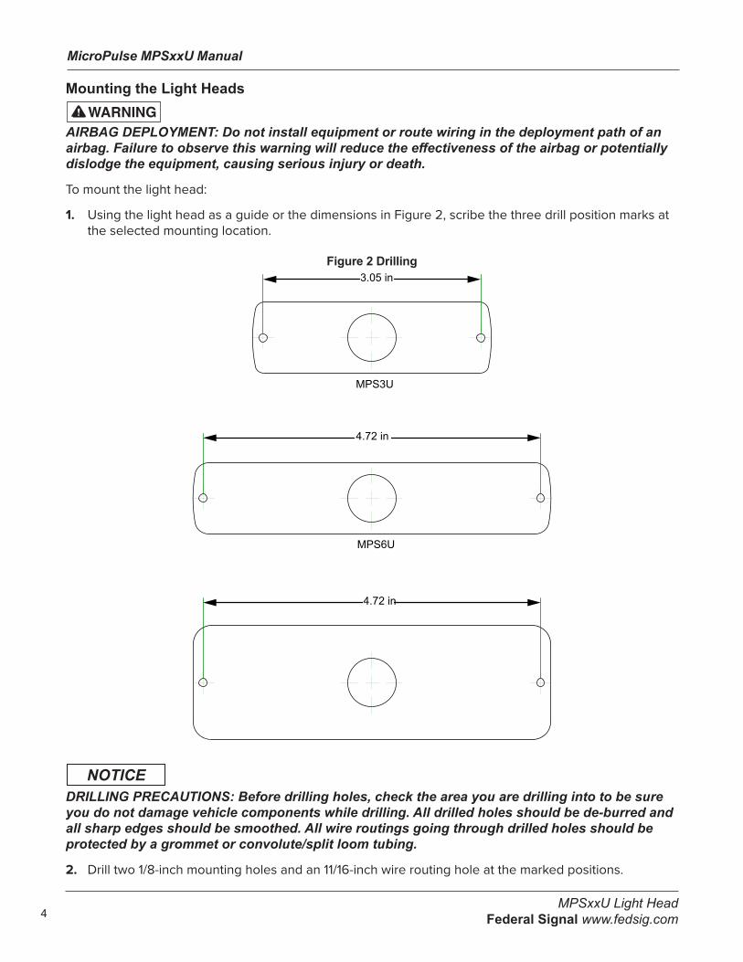
1. Using the light head as a guide or the dimensions in Figure 2, scribe the three drill position marks at the selected mounting location.
Figure 2 Drilling3.05 in
MPS3U
4.72 in
MPS6U
4.72 in
MPS12U
DRILLING PRECAUTIONS: Before drilling holes, check the area you are drilling into to be sure you do not damage vehicle components while drilling. All drilled holes should be de-burred and all sharp edges should be smoothed. All wire routings going through drilled holes should be protected by a grommet or convolute/split loom tubing.
2. Drill two 1/8-inch mounting holes and an 11/16-inch wire routing hole at the marked positions.

MicroPulse MPSxxU Manual
5MPSxxU Light Head Federal Signal www.fedsig.com
Installing and Maintaining the Light HeadWiring the Light Head
REVERSE POLARITY/MISWIRING: To avoid damage to the light, ensure that the input voltage is the same as the voltage rating of the light. Ensure that correct polarity is observed.The unit must be properly fused with a 2 A fuse.
To wire the light head:
1. Determine the required functions and the length of wires needed to access them. A five-conductor cable can be selected for a full-featured installation. For lengths up to 15 feet (5 m), use a minimum of 18 AWG (1 mm2) wire. For lengths over 15 feet, use a minimum of 16 AWG (1.5 mm2) wire. Before wiring the light head, refer to Table 3 for the function of each wire.
Table 3 Wire connections
Color Description Connection Point Black Ground Battery Negative Red Mode 1 Switched Positive 12-24 Vdc White Mode 2 Switched Positive 12-24 Vdc Brown Mode 3 Switched Positive 12-24 Vdc Green Program/FSLink 12-24 Vdc (for Programming Only)
2. Strip 1/4 inch (5 mm) of insulation from the ends of the installer-supplied wires.
3. Use insulated butt connectors to connect the wires to the power cable of the light head. Ensure that the connectors are securely crimped and properly insulated.
4. Connect the end of the fuse holder to the positive (+) terminal of the voltage source.
5. Connect the black wire from the light head to a known good vehicle ground as close to the light head as practical.
6. The black wire is ground and must be connected to a suitable chassis ground if it cannot be taken directly to the negative terminal of the battery.
7. The green wire has multiple functions: If using the light head with an external flasher, this wire is tied directly to chassis ground. This allows an external flasher to control each color independently via the Mode wires. If using the light head’s internal flasher, it is the runner wire that synchronizes FSLink™ equipped products, and it serves as the function/pattern programming wire.
8. The red wire powers the light head in Mode 1 when connected to a fused, positive voltage.
9. The white wire powers the light head in Mode 2 when connected to a fused, positive voltage.
10. The brown wire powers the light head in Mode 3 when connected to a fused, positive voltage.
NOTE: Mode 3 overrides Mode 2, which overrides Mode 1.

MicroPulse MPSxxU Manual
6MPSxxU Light Head
Federal Signal www.fedsig.com
Configuring the Light Head If the light head’s operating functions are to be changed from the default perform the following steps.
Selecting a Flash Pattern
LIGHT HAZARD: To be an effective warning device, this product produces a bright light that can be hazardous to your eyesight when viewed at a close range. Do not stare directly into this lighting product at a close range or permanent damage to your eyesight may occur.
For available flash patterns, see Table 4 on page 9.
To select a flash pattern:
1. Select Mode 1 (red wire), Mode 2 (white wire), or Mode 3 (brown wire).
2. Apply power (+12-24 Vdc) to that wire.
3. To activate FSLink™, tap the green wire to + 12-24 Vdc until the desired pattern is reached.
NOTE: When tapping the green wire to change patterns, do not hold power for longer than one second, or other features of the light head can change.
Selecting FSLINK Sync or Alt FlashThe light head can synchronize with other light heads. It will either flash with or alternate the timing of the flashes with other light heads. Select this feature separately for each mode.
To synchronize your selected flash pattern:
1. Activate a Mode.
2. Connect and hold the green wire to the positive voltage source until the light head pulses twice, and then release it. The light head switches from its initial setting to its opposite. “Sync Flash” becomes “Alternate Flash” or vice versa.
3. To synchronize, after setup, connect the green wires together.
For this feature to operate, permanently connect all green wires after all light heads in the system are configured.
NOTE: For sync to work properly, all light heads connected via FSLink must have the same pattern selected for all modes used.
Selecting Flash Color(s) (if equipped with more than one color) The light head can be made to either flash a single, dual, or triple color. This is done separately for each Mode.
To select the number of colors for a mode’s flash pattern:
1. Activate the mode for which this color feature is to be set.
2. Connect and hold the green wire to the power until the light head pulses three times, and then release it.

MicroPulse MPSxxU Manual
7MPSxxU Light Head Federal Signal www.fedsig.com
3. The light head switches from its initial setting to add the next available number of colors.
4. Repeat until the desired color(s) are flashing.
NOTE: Changing the Flash Color(s) also resets the Color Order (see below).
Selecting the Color Order (if “Flash Colors” is set to flash more than one color)You can set the order in which a light head flashes the colors. The order is selected separately for each Mode.
To select the color order:
1. Activate the Mode for which this color feature is to be set.
2. Hold the green wire to the positive voltage source until the light head pulses four times, and then release the wire. The light head switches color from the initial setting to the next color. For example, a dual-color, amber-red light head set to flash amber and then red will change to flashing red and then amber.
Selecting the Split Zone Flash Settings (MPS6U and MPS12U Only)You can set whether the light head flashes all zones together or alternates them. The split zone setting is selected separately for each Mode.
To select the split zone settings:
1. Activate the Mode for which this split zone feature is to be set.
2. Hold the green wire to the positive voltage source until the light head pulses five times, and then release the wire. The light head switches zone settings from the initial setting to the next available split zone setting. For example, the MPS6U can switch from all zones simultaneous flashing to vertical split flashing. The MPS12U includes vertical, horizontal, and quad-x split zone settings.
Selecting the BrightnessYou can set one of three brightness settings for each mode (Full, Dim, and Cruise).
To select the brightness setting:
1. Activate the Mode for which this feature is to be set.
2. Hold the green wire to the positive voltage source until the light head pulses six times, and then release the wire. The light head switches intensity from the initial setting to the next available intensity setting.
Resetting the Light Head to the Default Settings To reset the light head mode to the default settings, apply power to the green wire while any Mode is powered.
Hold the wire to the power source until the light head pulses seven times and then remove power. All Modes and options will reset to the default configuration.
NOTE: If the green wire is held for more than 8 seconds, no change occurs and the light head will

MicroPulse MPSxxU Manual
8MPSxxU Light Head
Federal Signal www.fedsig.com
resume normal operation.
Cleaning the Light HeadsPeriodically cleaning the light heads using proper procedures and compatible cleaners will prolong their service life.
CRAZING/CLEANING SOLUTIONS: The use of cleaning solutions, such as strong detergents, solvents, and petroleum products, can cause crazing (cracking) of the light bar lens and reflectors. To clean the reflectors, use a soft, damp cloth. To clean the lens, use a soft cloth and a solution of water and a mild detergent.
CRAZING/CHEMICALS: Crazed, cracked or faded lenses or reflectors reduce the light output and the effectiveness of the lighting system. A lens or reflectors showing this type of aging must be replaced. Failure to follow this warning may result in bodily injury or death.

MicroPulse MPSxxU Manual
9MPSxxU Light Head Federal Signal www.fedsig.com
Quick ReferenceTable 4 Light Head Wiring
Wire Internal Flasher Mode External Flasher ModeRed To +VDC for Mode 1 To +VDC for Color 1 SteadyWhite To +VDC for Mode 2 To +VDC for Color 2 SteadyBrown To +VDC for Mode 3 To +VDC for Color 3 SteadyGreen FSLink Sync To - Chassis Ground
+VDC for Programming
Black To - Chassis Ground To - Chassis Ground
Table 5 Programming Quick Reference
Program Wire Held Feedback Programming Sel.Less than 1 Second 1 Flash Pattern SelectBetween 1-2 Seconds 2 Flashes FSLink Sync or Alt Between 2-3 Seconds 3 Flashes Flash Color(s) SelectBetween 3-4 Seconds 4 Flashes Color Order SelectBetween 4-5 Seconds 5 Flashes Split Flash SelectBetween 5-6 Seconds 6 Flashes Brightness SelectBetween 6-7 Seconds 7 Flashes Default ALL Modes
Table 6 Internal Flasher Mode Defaults
Mode 1 - Flash Pattern #10 Steady Burn, Cruise IntensityMode 2 - Flash Pattern #1 Triple 92.3 FPM, All ColorsMode 3 - Flash Pattern #10 Steady Burn, Full Intensity
Table 7 Flash Patterns
No. Description Flash Pattern Compliance1 Triple 92.3 SAE/NFPA/TRIPLE-K2 Triple 90 SAE/NFPA/TRIPLE-K3 Single 122 SAE/R65/NFPA/TRIPLE-K4 Single 75 SAE/TITLE13/NFPA/TRIPLE-K5 Single 90 SAE/TITLE13/NFPA/TRIPLE-K6 Single 113 SAE/TITLE13/NFPA/TRIPLE-K7 Cruise Flicker n/a8 Mega 375 -9 Random SAE/TITLE1310 Steady Burn n/a11 Single 75 SAE/TITLE13/NFPA/TRIPLE-K12 Single 120 SAE/TITLE13/NFPA/TRIPLE-K13 Double 80 SAE/TITLE13/NFPA/TRIPLE-K14 Double 120 SAE/TITLE13/R65/NFPA/
TRIPLE-K15 Triple 80 SAE/TITLE13/NFPA/TRIPLE-K16 Triple 120 SAE/TITLE13/NFPA/TRIPLE-K17 Quad 60 SAE/TITLE1318 Quad 75 SAE/TITLE13/NFPA/TRIPLE-K19 Quad 95 SAE/TITLE13/NFPA/TRIPLE-K20 FedPulse 75 SAE/TITLE1321 Quint 75 SAE/TITLE13/NFPA/TRIPLE-K22 Seven X 80 SAE/TITLE13/NFPA/TRIPLE-K23 SingleQuad 120 SAE/TITLE13/NFPA/TRIPLE-K24 Decelerating 60 SAE/TITLE1325 Accelerating 60 SAE/TITLE13

MicroPulse MPSxxU Manual
10MPSxxU Light Head
Federal Signal www.fedsig.com
Getting Technical SupportFor technical support, please contact:
Federal Signal Corporation Service Department Phone: 1-800-433-9132 Fax: 1-800-343-9706 Email: [email protected]
Getting Repair ServiceThe Federal Signal factory provides technical assistance with any problems that cannot be handled locally. Any product returned to Federal Signal for service, inspection, or repair must be accompanied by a Return Material Authorization (RMA). Obtain a RMA from a local Distributor or Manufacturer’s Representative. Provide a brief explanation of the service requested, or the nature of the malfunction.
Address all communications and shipments to the following:
Federal Signal Corporation Service Department 2645 Federal Signal Dr. University Park, IL 60484-3167

MicroPulse MPSxxU Manual
11MPSxxU Light Head Federal Signal www.fedsig.com
Limited Warranty This product is subject to and covered by a limited warranty, a copy of which can be found at www.fedsig.com/SSG-Warranty. A copy of this limited warranty can also be obtained by written request to Federal Signal Corporation, 2645 Federal Signal Drive, University Park, IL 60484, email to [email protected] or call +1 708-534-3400.
This limited warranty is in lieu of all other warranties, express or implied, contractual or statutory, including, but not limited to the warranty of merchantability, warranty of fitness for a particular purpose and any warranty against failure of its essential purpose.

2645 Federal Signal DriveUniversity Park, Illinois 60484-3167
www.fedsig.com
Customer SupportPolice/Fire-EMS: 800-264-3578 • +1 708 534-3400 Work Truck: 800-824-0254 • +1 708 534-3400 Technical Support: 800-433-9132 • +1 708 534-3400
© Copyright 2020-2021 Federal Signal Corporation
All product names or trademarks are properties of their respective owners.