26 e fields & cond cr 3/98 - physics2000 - relativity...
TRANSCRIPT

CHAPTER26 ELECTRIC FIELDSAND CONDUCTORS
In this chapter we will first discuss the behavior ofelectric fields in the presence of conductors, and thenapply the results to three practical devices, the Van deGraaff generator, the electron gun, and the parallelplate capacitor. Each of these examples provides notonly an explanation of a practical device, but also helpsbuild an intuitive picture of the concept of electricvoltage.
Chapter 26Electric Fieldsand Conductors
ELECTRIC FIELDINSIDE A CONDUCTORIf we have a piece of metal a few centimeters across asillustrated in Figure (1), and suddenly turn on anelectric field, what happens? Initially the field goesright through the metal. But within a few pico seconds(1 pico second = 10–12 seconds) the electrons in themetal redistribute themselves inside the metal creatingtheir own field that soon cancels the external appliedelectric field, as indicated in Figure (2).
metal
E = ?
Figure 2If you place a chunk of metal in anexternal electric field, the electrons moveuntil there is no longer a force on them.
––––
++++
Figure 1What is the electric field inside a chunk of metal?Metals have conduction electrons that are free to move.If there were an electric field inside the metal, theconduction electrons would be accelerated by the field.

26-2 Electric Fields and Conductors
The very concept of an electrical conductor requiresthat, in the steady state, there be no electric field inside.To see why, imagine that there is a field inside. Sinceit is a conductor, the electrons in the conductor are freeto move. If there is a field inside, the field will exert aforce on the electrons and the electrons will move.They will continue to move until there is no force onthem, i.e., until there is no field remaining inside. Theelectrons must continue to move until the field theycreate just cancels the external field you applied.
Surface ChargesWhere does the redistributed charge have to go in orderto create an electric field that precisely cancels theapplied electric field? Gauss’ law provides a remark-ably simple answer to this question. The redistributedcharge must reside on the surface of the conductor.This is because Gauss’ law requires that there be no netcharge inside the volume of a conductor.
To see why, let us assume that a charge Q is inside aconductor as shown in Figure (3). Draw a smallGaussian surface around Q. Then by Gauss’ law theflux Φ = E⋅A coming out through the Gaussian sur-face must be equal to Qin ε0Qin ε0 where Qin is the net chargeinside the Gaussian surface. But if there is no fieldinside the conductor, if E = 0, then the flux E⋅A outthrough the Gaussian surface must be zero, and there-fore the charge Qin must be zero.
If there is no charge inside the conductor, then the onlyplace any charge can exist is in the surface. If there isa redistribution of charge, the redistributed charge mustlie on the surface of the conductor.
Figure (4) is a qualitative sketch of how surface chargecan create a field that cancels the applied field.
Figure 4cInside the block of metal the fields cancel. Theresult is that the external field on the left stops onthe negative surface charge. The field on the rightstarts again on the positive surface charge.
––––
++++
E + E' = 0 EE
–
+
Figure 4bIn response to the electric field, the electrons move tothe left surface of the metal, leaving behind positivecharge on the right surface. These two surface chargeshave their own field E ′′ that is oppositely directed to E.
– +
EE'– +
– +– +
metalappliedelectricfield E
Figure 4aAn external field is applied to a block of metal.
Figure 3Is there any electric charge inside a conductor? Tofind out, draw a Gaussian surface around thesuspected charge. Since there is no electric fieldinside the conductor, there is no flux out throughthe surface, and therefore no charge inside.
+Q

26-3
Gauss’ law can be used to calculate how much chargemust be at the surface if a field of strength E isimpinging as shown in Figure (5). In that figure wehave drawn a small pill box shaped Gaussian surface,with one end in the conductor and the other outside inthe field E . If the area of the end of the pill box is dA,then the flux out of the pill box on the right is
Φout = EdA.
Let σ coulombs/meter2 be the charge density on thesurface. The amount of the conductor’s surface sur-rounded by the pill box is dA, thus the amount of chargeinside the pill box is
Amount of chargeinside the
Gaussian surface≡ Qin = σdA
By Gauss’ law, the flux Φout = EdA must equal 1/ε0times the total charge inside the Gaussian surface andwe get
Φout =
Qin
ε0=
σdAε0
= EdA
The dA's cancel and we are left with
E =
σ
ε0
E = electric field at the conductor
σ = charge densityat the surface (1)
Equation (1) gives a simple relation between the strengthof the electric field at the surface of a conductor, and thesurface charge density σ at that point. Just rememberthat the field E must be perpendicular to the surface ofthe conductor. (If the applied field was not originallyperpendicular to the surface, surface charges will slidealong the surface, reorienting the external field to makeit perpendicular.)
To appreciate how far we have come with the conceptsof fields and Gauss’ law, just imagine trying to deriveEquation (1) from Coulomb’s law. We wouldn’t evenknow how to begin.
We will now work an example and assign a fewexercises to build an intuition for the behavior of fieldsand conductors. Then we will apply the results to somepractical devices.
In Figure (4a) we see the electric field just after it hasbeen turned on. Since the electrons in the metal arenegatively charged (q = -e), the force on the electronsF = (-e) E is opposite to E and directed to the left.
In Figure (4b), electrons have been sucked over to theleft surface of the metal, leaving positive charge on theright surface. The negative charge on the left surfacecombined with the positive charge on the right pro-duced the left directed field E′ shown by the dottedlines. The oppositely directed fields E and E′ cancel inFigure (4c) giving no net field inside the metal.
Surface Charge DensityWhen a field E impinges on the surface of a conductor,it must be oriented at right angles to the conductor asshown in Figure (5). The reason for this is that if E hada component E| | parallel to the surface, E| | would pullthe movable charge along the surface and change thecharge distribution. The only direction the surfacecharge cannot be pulled is directly out of the surface ofthe conductor, thus for a stable setup the electric fieldat the surface must be perpendicular as shown.
+
E
E
surfacechargeσ coul/m 2
areadA
++++++++
metal
Charged surface inside pillbox. The amount of charge on this surface is σdA
Figure 5To calculate the surface charge density, we draw asmall cylindrical pill box of cross-sectional areadA. We then equate the flux of electric field outthrough the right surface of the pill box to
1/εεotimes the charge inside the pill box.
26-4 Electric Fields and Conductors
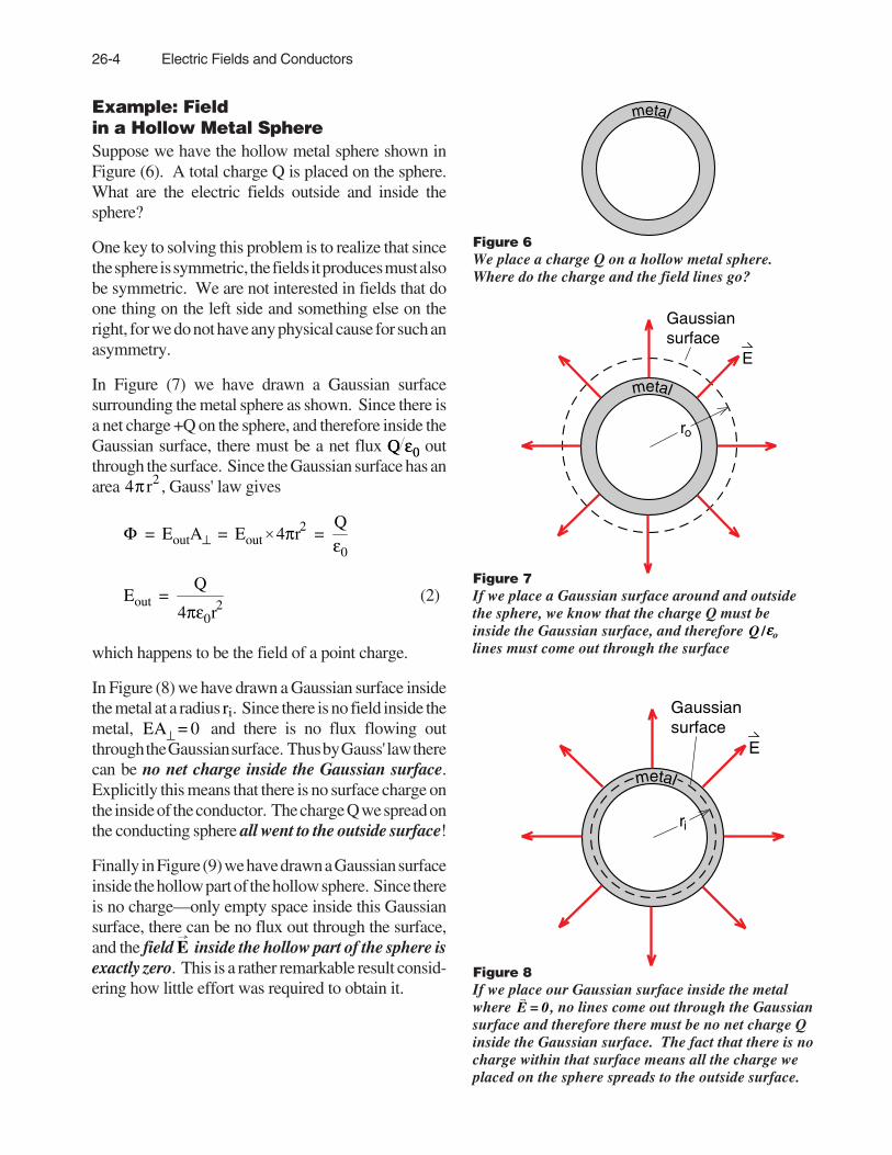
Example: Fieldin a Hollow Metal SphereSuppose we have the hollow metal sphere shown inFigure (6). A total charge Q is placed on the sphere.What are the electric fields outside and inside thesphere?
One key to solving this problem is to realize that sincethe sphere is symmetric, the fields it produces must alsobe symmetric. We are not interested in fields that doone thing on the left side and something else on theright, for we do not have any physical cause for such anasymmetry.
In Figure (7) we have drawn a Gaussian surfacesurrounding the metal sphere as shown. Since there isa net charge +Q on the sphere, and therefore inside theGaussian surface, there must be a net flux Q ε0Q ε0 outthrough the surface. Since the Gaussian surface has anarea 4π r2 , Gauss' law gives
Φ = EoutA⊥ = Eout × 4πr2 =Qε0
Eout =Q
4πε0r2(2)
which happens to be the field of a point charge.
In Figure (8) we have drawn a Gaussian surface insidethe metal at a radius ri. Since there is no field inside themetal, EA⊥ = 0 and there is no flux flowing outthrough the Gaussian surface. Thus by Gauss' law therecan be no net charge inside the Gaussian surface.Explicitly this means that there is no surface charge onthe inside of the conductor. The charge Q we spread onthe conducting sphere all went to the outside surface!
Finally in Figure (9) we have drawn a Gaussian surfaceinside the hollow part of the hollow sphere. Since thereis no charge—only empty space inside this Gaussiansurface, there can be no flux out through the surface,and the field E inside the hollow part of the sphere isexactly zero. This is a rather remarkable result consid-ering how little effort was required to obtain it.
E
ro
Gaussiansurface
metal
metal
Figure 7If we place a Gaussian surface around and outsidethe sphere, we know that the charge Q must beinside the Gaussian surface, and therefore Q /εεo
lines must come out through the surface
Figure 8If we place our Gaussian surface inside the metalwhere E = 0, no lines come out through the Gaussiansurface and therefore there must be no net charge Qinside the Gaussian surface. The fact that there is nocharge within that surface means all the charge weplaced on the sphere spreads to the outside surface.
E
ri
Gaussiansurface
metal
Figure 6We place a charge Q on a hollow metal sphere.Where do the charge and the field lines go?

26-5
Exercise 2A chunk of metal has an irregularly shaped cavity insideas shown in Figure (11). There are no holes and thecavity is completely surrounded by metal.
The metal chunk is struck by lightning which produceshuge electric fields and deposits an unknown amount ofcharge on the metal, but does not burn a hole into thecavity. Show that the lightning does not create anelectric field inside the cavity. (For a time on the order ofpico seconds, an electric field will penetrate into the metal, butif the metal is a good conductor like silver or copper, thedistance will be very short.)
(What does this problem have to do with the advice tostay in a car during a thundershower?)
metal
cavity
Figure 11A chunk of metal with a completely enclosed hollowcavity inside is struck by lightning.
Exercise 3A positive charge +Q placedon a conducting sphere of ra-dius R, produces the electricfield shown.
a) What is the charge densityσ on the surface of the sphere?
b) Use Equation (1) to find a formula for the magnitudeof the electric field E produced by the surface chargedensity σ .
c) How does the field calculated in part b) compare withthe strength of the electric field a distance R from a pointcharge Q?
Exercise 4
Repeat Exercise 1 assuming that the conducting spherehas a net charge of – Q. Does the charge on theconducting sphere have any effect on the fields insidethe sphere? Why is there no field outside the sphere?
E
ri
Gaussiansurface
metal
Figure 9If the Gaussian surface is drawn inside the hollow cavityas shown, then there is no charge inside the Gaussiansurface. Thus no field lines emerge through theGaussian surface, and E must be zero inside the cavity.
Exercise 1A positive charge +Q is surrounded concentrically by aconducting sphere with an inner radius ra and outerradius rb as shown in Figure (10). The conductingsphere has no net charge. Using Gauss’ law, find theelectric field inside the hollow section (r < ra) , inside theconducting sphere (ra <r <rb) and outside the sphere
(r > rb). Also calculate the surface charge densities onthe inner and outer surfaces of the conducting sphere.Show that Equation (1) applies to the charge densitiesyou calculate.
+Qrb
ra
Figure 10Start with an uncharged hollow metal sphere and placea charge +Q inside. Use Gauss' law to determine theelectric field and the surface charges throughout theregion.
E
R
26-6 Electric Fields and Conductors
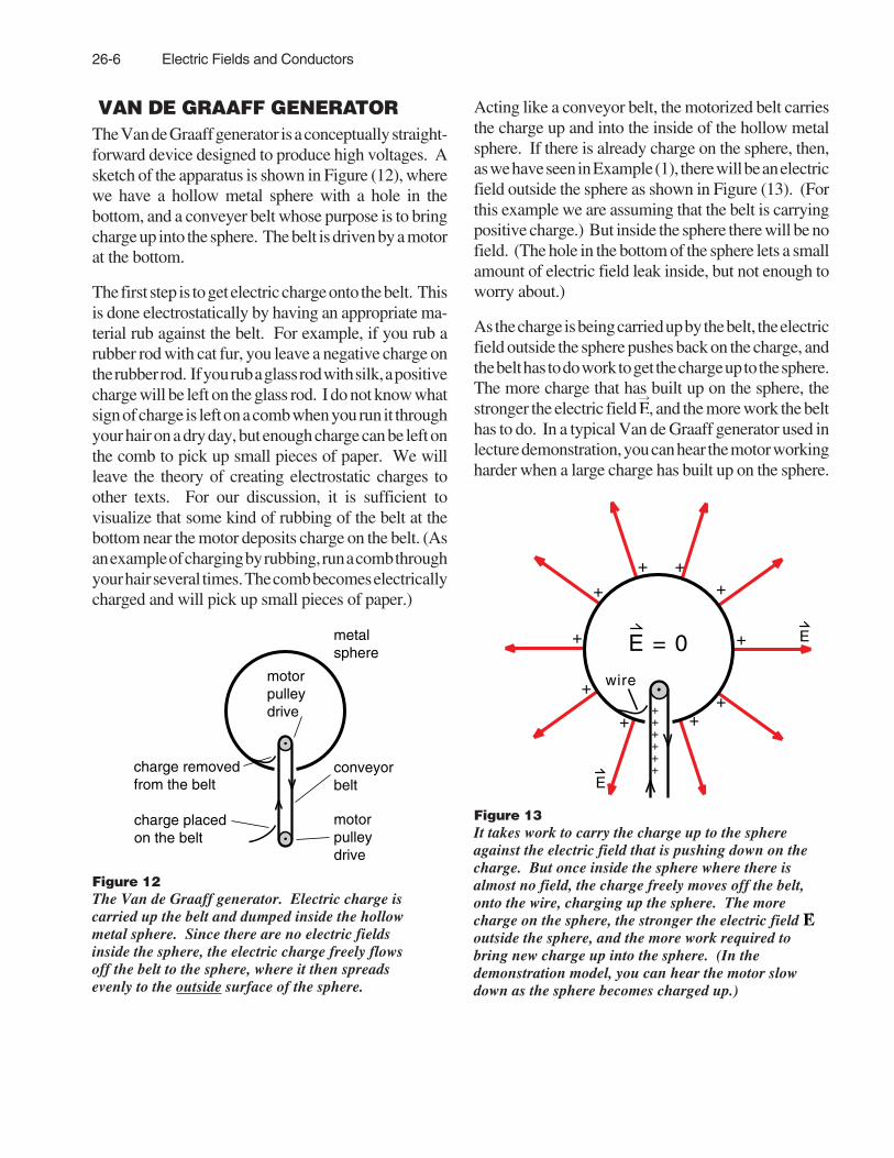
VAN DE GRAAFF GENERATORThe Van de Graaff generator is a conceptually straight-forward device designed to produce high voltages. Asketch of the apparatus is shown in Figure (12), wherewe have a hollow metal sphere with a hole in thebottom, and a conveyer belt whose purpose is to bringcharge up into the sphere. The belt is driven by a motorat the bottom.
The first step is to get electric charge onto the belt. Thisis done electrostatically by having an appropriate ma-terial rub against the belt. For example, if you rub arubber rod with cat fur, you leave a negative charge onthe rubber rod. If you rub a glass rod with silk, a positivecharge will be left on the glass rod. I do not know whatsign of charge is left on a comb when you run it throughyour hair on a dry day, but enough charge can be left onthe comb to pick up small pieces of paper. We willleave the theory of creating electrostatic charges toother texts. For our discussion, it is sufficient tovisualize that some kind of rubbing of the belt at thebottom near the motor deposits charge on the belt. (Asan example of charging by rubbing, run a comb throughyour hair several times. The comb becomes electricallycharged and will pick up small pieces of paper.)
Acting like a conveyor belt, the motorized belt carriesthe charge up and into the inside of the hollow metalsphere. If there is already charge on the sphere, then,as we have seen in Example (1), there will be an electricfield outside the sphere as shown in Figure (13). (Forthis example we are assuming that the belt is carryingpositive charge.) But inside the sphere there will be nofield. (The hole in the bottom of the sphere lets a smallamount of electric field leak inside, but not enough toworry about.)
As the charge is being carried up by the belt, the electricfield outside the sphere pushes back on the charge, andthe belt has to do work to get the charge up to the sphere.The more charge that has built up on the sphere, thestronger the electric field E, and the more work the belthas to do. In a typical Van de Graaff generator used inlecture demonstration, you can hear the motor workingharder when a large charge has built up on the sphere.
+
+ ++
+
+++
+
+
wire
E = 0 E
++++++
E
metalsphere
conveyorbelt
motorpulleydrive
motorpulleydrive
charge placedon the belt
charge removedfrom the belt
Figure 12The Van de Graaff generator. Electric charge iscarried up the belt and dumped inside the hollowmetal sphere. Since there are no electric fieldsinside the sphere, the electric charge freely flowsoff the belt to the sphere, where it then spreadsevenly to the outside surface of the sphere.
Figure 13It takes work to carry the charge up to the sphereagainst the electric field that is pushing down on thecharge. But once inside the sphere where there isalmost no field, the charge freely moves off the belt,onto the wire, charging up the sphere. The morecharge on the sphere, the stronger the electric field Eoutside the sphere, and the more work required tobring new charge up into the sphere. (In thedemonstration model, you can hear the motor slowdown as the sphere becomes charged up.)

26-7
When the charge gets to the sphere how do we get it offthe belt onto the sphere? When the sphere already hasa lot of positive charge on it, why would the positivecharge on the belt want to flow over to the sphere?Shouldn’t the positive charge on the belt be repelled bythe positive sphere?
Here is where our knowledge of electric fields comesin. As illustrated in Figure (13), there may be verystrong electric fields outside the sphere, but inside thereare none. Once the conveyor belt gets the charge insidethe sphere, the charge is completely free to run off to thesphere. All we need is a small wire that is attached tothe inside of the sphere that rubs against the belt. In fact,the neighboring + charge on the belt helps push thecharge off the belt onto the wire.
Once the charge is on the wire and flows to the insideof the sphere, it must immediately flow to the outsideof the sphere where it helps produce a stronger field Eshown in Figure (13).
Electric DischargeWhen a large amount of charge has accumulated on themetal sphere of the Van de Graaff generator, we canproduce some very strong fields and high voltages. Wecan estimate the voltage by bringing a grounded sphereup to the Van de Graaff generator as shown in Figure(14). A voltage of about 100,000 volts is required tomake a spark jump about an inch through air. Thus ifwe get a spark about 2 inches long between the Van deGraaff generator and the grounded sphere, we havebrought enough charge onto the generator sphere tocreate a voltage of about 200,000 volts. (The length ofthe sparks acts as a crude voltmeter!)
As an exercise, let us estimate how many coulombs ofcharge must be on the Van de Graaff generator sphereto bring it up to a voltage of 200,000 volts.
Outside the Van de Graaff generator sphere, the electricfield is roughly equal to the electric field of a pointcharge. Thus the voltage or electric potential of thesphere should be given by Equation (25-4) as
V = Q
4πε0r (25-4)
where r is the radius of the Van de Graaff generatorsphere. (Remember that r is not squared in the formulafor potential energy or voltage.)
Let us assume that r = 10 cm or .1 m, and that the voltageV is up to 200,000 volts. Then Equation (25-4) gives
Q = 4πε0rV
= 4π × 9 × 10-12 × .1 × 200,000
Q ≈ 2 × 10⁻⁶ coulombs
A couple millionth’s of a coulomb of charge is enoughto create 200,000 volt sparks. As we said earlier, awhole coulomb is a huge amount of charge!
Figure 14We can discharge the Van de Graaff generatorby bringing up a grounded sphere as shown.Since about 100,000 volts are required to make aspark one inch long, we can use the maximumlength of sparks to estimate the voltage producedby the Van de Graaff generator.
motor
metal grounding plate
wire to water pipe
groundingwire
spark
insulatedsupport
groundedmetal sphere

26-8 Electric Fields and Conductors
GroundingThe grounded sphere in Figure (14) that we used toproduce the sparks, provides a good example of theway we use conductors and wires.
Beneath the Van de Graaff generator apparatus wehave placed a large sheet of aluminum called a ground-ing plane that is attached to the metal pipes and theelectrical ground in the room. (Whenever we haveneglected to use this grounding plane during a demon-stration we have regretted it.) We have attached acopper wire from the grounding plane to the “grounded”sphere as shown.
Thus in Figure (14), the grounding plane, the room’smetal pipes and electrical ground wires, and thegrounded sphere are all attached to each other via aconductor. Now there can be no electric field inside aconductor, therefore all these objects are at the sameelectric potential or voltage. (If you have a voltagedifference between two points, there must be an electricfield between these two points to produce the voltagedifference.) It is common practice in working withelectricity to define the voltage of the water pipes (or ametal rod stuck deeply into the earth) as zero volts or“ground”. (The ground wires in most home wiring areattached to the water pipes.) Any object that is con-nected by a wire to the water pipes or electrical groundwire is said to be grounded. The use of the earth as thedefinition of the zero of electric voltage is much likeusing the floor of a room as the definition of the zero ofthe gravitational potential energy of an object.
In Figure (14), when the grounded sphere is brought upto the Van de Graaff generator and we get a 2 inch longspark, the spark tells us that the Van de Graaff spherehad been raised to a potential of at least 200,000 voltsabove ground.
Van de Graaff generators are found primarily in twoapplications. One is in science museums and lecturedemonstration to impress visitors and students. Theother is in physics research. Compared to modernaccelerators, the 200,000 volts or up to 100 millionvolts that Van de Graaff generators produce is small.But the voltages are very stable and can be preciselycontrolled. As a result the Van de Graaff’s makeexcellent tools for studying the fine details of thestructure of atomic nuclei.
THE ELECTRON GUNIn Figure (15) we have a rough sketch of a televisiontube with an electron gun at one end to create a beamof electrons, deflection plates to move the electronbeam, and a phosphor screen at the other end to producea bright spot where the electrons strike the end of thetube.
Figure (16) illustrates how a picture is drawn on atelevision screen. The electron beam is swept horizon-tally across the face of the tube, then the beam is moveddown one line and swept horizontally again. AnAmerican television picture has about 500 horizontallines in one picture.
As the beam is swept across, the brightness of the spotcan be adjusted by changing the intensity of the elec-tron beam. In Figure (16), line 3, the beam starts outbright, is dimmed when it gets to the left side of theletter A, shut off completely when it gets to the blackline, then turned on to full brightness to complete theline. In a standard television set, one sweep across thetube takes about 60 microseconds. To draw the finedetails you see on a good television set requires that theintensity of the beam can be turned up and down in littlemore than a tenth of a microsecond.
Figure 15Cathode ray tubes, like the one shown above, arecommonly used in television sets, oscilloscopes, andcomputer monitors. The electron beam (otherwiseknown as a "cathode ray") is created in the electrongun, is aimed by the deflection plates, and produces abright spot where it strikes the phosphor screen.
brightspot
electron beamdeflectionplates
electrongun
phosphorscreen

26-9
The FilamentAs shown in Figure (17), the source of the electrons inan electron gun is the filament, a piece of wire that hasbeen heated red-hot by the passage of an electriccurrent. At these temperatures, some of the electronsin the filament gain enough thermal kinetic energy toevaporate out through the surface of the wire. Thewhite coating you may see on a filament reduces theamount of energy an electron needs to escape outthrough the metal surface, and therefore helps producea more intense beam of electrons. At standard tempera-ture and pressure, air molecules are about 10- molecu-lar diameters apart as indicated in Figure (18). There-fore if the filament is in air, an electron that hasevaporated from the filament can travel, at most, a fewhundred molecular diameters before striking an airmolecule. This is why the red-hot burner on an electricstove does not emit a beam of electrons. The only waywe can get electrons to travel far from the filament is toplace the filament in a vacuum as we did in Figure (17).The better the vacuum, the farther the electrons cantravel.
The heart of this system is the electron gun whichcreates the electron beam. The actual electron gun ina television tube is a complex looking device withindirect heaters and focusing rings all mounted on thebasic gun. What we will describe instead is a student-built gun which does not produce the fine beam of acommercial gun, but which is easy to build and easy tounderstand.
Figure 16The letter A on a TV screen. To construct animage the electron beam is swept horizontally, andturned up where the picture should be bright andturned down when dark. The entire image consistsof a series of these horizontal lines, evenly spaced,one below the other.
•••
•• •
••••
•• • •
•• •• •
vacuum
glass testtube
heatedfilament
electrons boiledoff surface offilament
to sourceof heating current
Figure 18Whenever we heat a metal to a high enoughtemperature, electrons boil out of the surface. But ifthere is air at standard pressure around, the electronsdo not get very far before striking an air molecule.
filament surface
airmoleculeelectron
Figure 17Source of the electrons. The tungsten filamentis heated by an electric current. When itbecomes red-hot, electrons boil out through thesurface. The white coating on the filamentmakes it easier for the electrons to escape.

26-10 Electric Fields and Conductors
Accelerating FieldOnce the electrons are out of the filament we use anelectric field to accelerate them. This is done by placinga metal cap with a hole in the end over the end of thefilament as shown in Figure (19). The filament and capare attached to a battery as shown in Figure (20) so thatthe cap is positively charged relative to the filament.
Intuitively the gun works as follows. The electrons arerepelled by the negatively charged filament and areattracted to the positively charged cap. Most of theelectrons rush over, strike, and are absorbed by the capas shown in Figure (21). But an electron headed for thehole in the cap discovers too late that it has missed thecap and goes on out to form the electron beam.
A picture of the resulting electron beam is seen inFigure (22). The beam is visible because some airremains inside the tube, and the air molecules glowwhen they are struck by an electron.
A Field PlotA field plot of the electric field lines inside the electrongun cap gives a more precise picture of what is happen-ing. Figure (23) is a computer plot of the field lines fora cylindrical filament inside a metal cap. We chose acylindrical filament rather than a bent wire filamentbecause it has the cylindrical symmetry of the cap andis therefore much easier to calculate and draw. But thefields for a wire filament are not too different.
First notice that the field lines are perpendicular to bothmetal surfaces. This agrees with our earlier discussionthat an electric field at the surface of a conductor cannothave a parallel component for that would move thecharge in the conductor. The second thing to note is thatdue to the unfortunate fact that the charge on theelectron is negative, the electric field points oppositelyto the direction of the force on the electrons. The forceis in the direction of -E.
Figure 20We then attach a battery to the metal cap so that thecap has a positive voltage relative to the filament.
+ + + + ++
+ + + + ++
– – – ––– – – ––
– +
beam ofelectrons
filament
metal capFigure 19To create a beam of electrons, we start by placing ametal cap with a hole in it, over the filament.
Figure 22Resulting electron beam.
Figure 21Electrons flow from the negative filamentto the positive cap. The beam of electronsis formed by the electrons that miss the capand go out through the hole.
+ +–
+ + + +++
++
+ + + + + +
– – – – –––––
––––––beam of electrons that missed the cap and went outthrough the hole
negative filament
positive cap
flow of electrons +
+

26-11
Equipotential PlotOnce we know the field lines, we can plot the equipo-tential lines as shown in Figure (24). The lines arelabeled assuming that the filament is grounded (0 volts)and that the cap is at 100 volts . The shape of theequipotentials, shown by dashed lines, does not changewhen we use different accelerating voltages, only thenumerical value of the equipotentials changes.
The reason that the equipotential lines are of suchinterest in Figure (24) is that they can also be viewed asa map of the electron’s kinetic energy.
Remember that the voltage V is the potential energy ofa unit positive test charge. A charge q has a potentialenergy qV, and an electron, with a charge – e , has anelectric potential energy – eV .
In our electron gun, the electrons evaporate from thefilament with very little kinetic energy, call it zero. Bythe time the electrons get to the 10-volt equipotential,their electric potential energy has dropped to (–e×10)joules, and by conservation of energy, their kineticenergy has gone up to (+e×10) joules. At the 50 voltequipotential the electron’s kinetic energy has risen to(e×50) joules, and when the electrons reach the 100volt cap, their energy is up to (e×100) joules. Thus theequipotential lines in Figure (24) provide a map of thekinetic energy of the electrons.
The electrons, however, do not move along the -E fieldlines. If they boil out of the filament with a negligiblespeed they will start moving in the direction -E. But asthe electrons gain momentum, the force -eE has lessand less effect. (Remember, for example, that for asatellite in a circular orbit, the force on the satellite isdown toward the center of the earth. But the satellitemoves around the earth in an orbit of constant radius.)In Figure (23), the dotted lines show a computer plot ofthe trajectories of the electrons at several points. Themost important trajectories for our purposes are thosethat pass through the hole in the cap and go out and formthe electron beam.
Exercise 5
Describe two other examples where an object does notmove in the direction of the net force acting on it.
equipotential lines
80 V50 V20 V
Figure 24Equipotential plot. We see that by the time theelectrons have reached the hole in the cap, theyhave crossed the same equipotential lines andtherefore have gained as much kinetic energy asthe electrons that strike the cap. (From a studentproject by Daniel Leslie and Elad Levy.)
trajectories ofindividual electrons
cylindricalfilament
electricfield
capFigure 23Plot of the electric field in the region between thefilament and the cap. Here we assume that we havea cylindrical filament heated by a wire inside.

26-12 Electric Fields and Conductors
ELECTRON VOLTAS A UNIT OF ENERGYWhat is perhaps most remarkable about the electrongun is that every electron that leaves the filament andstrikes the cap gains precisely the same kinetic energy.If we use a battery that produces 100 volt acceleratingvoltage, then every electron gains precisely (e×100)joules of kinetic energy. This is also true of theelectrons that miss the cap and go out and form theelectron beam.
The amount of energy gained by an electron that fallsthrough a 1 volt potential is (e×1 volt) = 1.6 x 10⁻¹⁹
joules. This amount of energy is called an electron voltand designated by the symbol eV.
1eV =
energy gained by an electronfalling through a 1 volt potential
= (e coulombs) × (1 volt)
= 1.6 x 10⁻¹⁹ joules
(3)
The dimensions in Equation (3) make a bit more sensewhen we realize that the volt has the dimensions ofjoule/coulomb, so that
1eV = e coulombs × 1
joulecoulomb
= (e) joules (3a)
The electron volt is an extremely convenient unit fordescribing the energy of electrons produced by anelectron gun. If we use a 100 volt battery to acceleratethe electrons, we get 100 eV electrons. Two hundredvolt batteries produce 200 eV electrons, etc.
To solve problems like calculating the speed of a 100eV electron, you need to convert from eV to joules. Theconversion factor is
1.6 × 10⁻¹⁹ joules
eVconversionfactor (4)
For example, if we have a 100 eV electron, its kineticenergy 1 21 2 mv2 is given by
KE = 1 21 2 mv2
= 100 eV × 1.6 × 10-19 jouleseV
(5)
Using the value m = 9.11 × 10⁻³¹ kg for the electronmass in Equation (5) gives
v =
2 × 100 × 1.6 × 10-19
9.11 × 10-31
= 6 × 10⁶ meterssec
(6)
which is 2% the speed of light.
In studies involving atomic particles such as electronsand protons, the electron volt is both a convenient andvery commonly used unit. If the electron volt is toosmall, we can measure the particle energy in MeV(millions of electron volts) or GeV (billions of electronvolts or Gigavolts).
1 MeV ≡ 106 eV
1 GeV ≡ 109 eV (6)
For example, if you work the following exercises, youwill see that the rest energies m0c2 of an electron and aproton have the values
electron rest energy = .51 MeV
proton rest energy = .93 GeV (7)
The reason that it is worth remembering that an electron’srest energy is about .5 MeV and a proton’s about 1 GeV,is that when a particle’s kinetic energy gets up towardits rest energy, the particle’s speed becomes a signifi-cant fraction of the speed of light and nonrelativisticformulas like 1/2 mv2 for kinetic energy no longerapply.

26-13
ExampleCalculate the rest energy of an electron in eV.
Solution:
E =
m0c2 joules
1.6 × 10⁻¹⁹ jouleseV
=9.11 × 10–31 × 3 × 108 2
1.6 × 10-19
= .51 × 106 eV
Exercise 6Calculate the rest energy of a proton in eV and GeV.
Exercise 7
What accelerating voltage must be used in an electrongun to produce electrons whose kinetic energy equalstheir rest energy?
About Computer PlotsOne final note in our discussion of the electron gun.You might feel that by using the computer plots inFigures (23) and (24) we have cheated a bit. Wehaven’t done the work ourselves, we let somebody (orsomething) else do the calculations for us and we arejust using their answers. Yes and no!
First of all, with a little bit of practice you can learn todraw sketches that are quite close to the computer plots.Use a trick like noting that field lines must be perpen-dicular to the surface of a conductor where they touchthe conductor. If two conductors have equal andopposite charge – if they were charged by a battery – allthe field lines that start on the positive conductor willstop on the negative one. Use any symmetry you canfind to help sketch the field lines and then sketch theequipotential lines perpendicular to the field lines.Some places it is easier to visualize the equipotentiallines, e.g., near the surface of a conductor, and thendraw in the perpendicular field lines.
The other point is that, for a number of practicalproblems the geometry of the conductors is compli-cated enough that only by using a computer can weaccurately plot the field lines and equipotentials. Butonce a computer plot is drawn, we do not have to worryabout how it was calculated. Like a hiker in a newterritory, we can use the computer plot as our contourmap to tell us the shape and important features of theterrain. For example in our field plots of the electrongun, we see that there is virtually no field out in front ofthe hole where the electrons emerge, therefore from thetime the electrons leave the hole they coast freely atconstant speed and energy down the tube.
Figure 24aAnother field plot by Leslie and Levy, showing theelectric field and equipotential lines in a gun with ashorter cap.
100 V80 V
50 V
20 V
0 V
equipotential lines

26-14 Electric Fields and Conductors
THE PARALLEL PLATE CAPACITOROur final example in this chapter of fields and conduc-tors is the parallel plate capacitor. Here we will workwith a much simpler field structure than for the electrongun, and will therefore be able to calculate field strengthsand voltages. The parallel plate capacitor serves as theprototype example of a capacitor, a device used through-out physics and electrical engineering for storing elec-tric fields and electric energy.
Suppose we take two circular metal plates of area A,separate them by a distance d, and attach a battery asshown in Figure (25). This setup is called a parallelplate capacitor, and the field lines and equipotential forthis setup are shown in the computer plot of Figure (26).
Except at the edges of the plates, the field lines gostraight down from the positive to the negative plate,and the equipotentials are equally spaced horizontallines parallel to the plates. If the plate separation d issmall compared to the diameter D of the plates, then wecan neglect the fringing of the field at the edge of theplates. The result is what we will call an ideal parallelplate capacitor whose field structure is shown in Figure(27). The advantage of working with this ideal capaci-tor is that we can easily derive the relationship betweenthe charging voltage V, and the charge Q.
Let us take a close look at what we have in Figure (27).The electric field lines E leave the positively chargedtop plate and go straight down to the negatively chargedbottom plate. Since all the lines starting at the top platestop at the bottom one, there must be an equal andopposite charge +Q and -Q on the two plates. There isno net charge on the capacitor, only a separation ofcharge. And because the field lines go straight down,nowhere do they get closer together or farther apart, thefield must have a uniform strength E between theplates.
We can use Gauss’ law to quickly calculate the fieldstrength E. The top plate has a charge Q, therefore thetotal flux out of the top plate must be Φ = Q/ε0 . But wealso have a field of strength E flowing out of a plate ofarea A. Thus flux of E flowing between the plates is
Φ = EA. Equating these two formulas for flux gives
Φ = EA =
Qε0
E =
Qε0A
(8)
We can relate the voltage V and the field strength E byremembering that E is the force on a unit test chargeand V is the potential energy of a unit test charge. IfI lift a unit positive test charge from the bottom platea distance d up to the top one, I have to exert anupward force of strength E for a distance d andtherefore do an amount of work E×d. This work isstored as the electric potential energy of the unit testcharge, and is therefore the voltage V:
V = E d (9)
Figure 26The electric field between and aroundthe edge of the capacitor plates.
+
––
+ +
–
+
–
+
–
+
–
+
–
+
–
+
–
+
–
+
– –
+ +
–
Figure 25The parallel plate capacitor. The capacitor is chargedup by connecting a battery across the plates as shown.
A d
battery
+
–
capacitor plates
Figure 27In our idealized parallel plate capacitor the fieldlines go straight from the positive to the negativeplate, and the field is uniform between the plates.
+
–
plate of area A
d
+
–
+
–
+
–
+
–
+
–
+
–
+
–
+
–
+
–
+
–
+
–
+
–

26-15
It may seem surprising, but V is also the voltage of thebattery (see Figure 25) used to charge up the capacitor.
There is also a simple relationship between the chargeQ on the capacitor plates and the voltage difference Vbetween them. Substituting the value of E fromEquation (8) into Equation (9) gives
V =
dε0A
Q (10)
Equation (10) makes an interesting prediction. If wehave a fixed charge Q on the capacitor (say we chargedup the capacitor and removed the battery), then if weincrease the separation d between the plates, the volt-age V will increase.
One problem with trying to measure this increase involtage is that if we attach a common voltmeter be-tween the plates to measure V, the capacitor willquickly discharge through the voltmeter. In order to seethis effect we must use a special voltmeter called anelectrometer that will not allow the capacitor to dis-charge. The classic electrometer, used in the 1800's, isthe gold leaf electrometer shown in Figures (28) and(29). When the top plate of the electrometer is charged,some of the charge flows to the gold leaves, forcing theleaves apart. The greater the voltage, the greater thecharge and the greater the force separating the leaves.Thus the separation of the leaves is a rough measure ofthe voltage.
In Figure (28), we see a gold leaf electrometer attachedto two metal capacitor plates. When the plates arecharged, the gold leaves separate, indicating that thereis a voltage difference between the plates.
In Figures (29a,b), we are looking through the elec-trometer at the edge of the capacitor plates. In goingfrom (29a) to (29b), we moved the plates apart withoutchanging the charge on the plates. We see that when theplates are farther apart, the gold leaves are moreseparated, indicating a greater voltage as predicted byequation (10).
Figure 28Gold leaf electrometer attachedto a parallel plate capacitor.
Figure 29bWithout changing the charge, the platesare moved further apart. The increasedseparation of the gold leaves shows thatthe voltage difference between thecapacitor plates has increased.
Figure 29aLooking through the electrometer at theedge of the charged capacitor plates.
g o l dleaves
26-16 Electric Fields and Conductors
Exercise 8
Two circular metal plates of radius 10 cm are separatedby microscope slide covers of thickness d = . 12 mm. Avoltage difference of 5 volts is set up between the platesusing a battery as shown in Figure (25). What is thecharge Q on the plates?
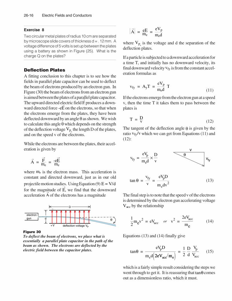
Deflection PlatesA fitting conclusion to this chapter is to see how thefields in parallel plate capacitor can be used to deflectthe beam of electrons produced by an electron gun. InFigure (30) the beam of electrons from an electron gunis aimed between the plates of a parallel plate capacitor.The upward directed electric field E produces a down-ward directed force -eE on the electrons, so that whenthe electrons emerge from the plates, they have beendeflected downward by an angle θ as shown. We wishto calculate this angle θ which depends on the strengthof the deflection voltage Vp, the length D of the plates,and on the speed v of the electrons.
While the electrons are between the plates, their accel-eration is given by
A = Fme
= -eEme
where me is the electron mass. This acceleration isconstant and directed downward, just as in our old
projectile motion studies. Using Equation (9) E = V/dfor the magnitude of E, we find that the downwardacceleration A of the electrons has a magnitude
A = eEme
= eVp
med
where Vp, is the voltage and d the separation of thedeflection plates.
If a particle is subjected to a downward acceleration fora time T, and initially has no downward velocity, itsfinal downward velocity vfy is from the constant accel-eration formulas as
vfy = AyT = eVp
med T
(11)
If the electrons emerge from the electron gun at a speedv, then the time T it takes them to pass between theplates is
T = Dv (12)
The tangent of the deflection angle θ is given by theratio vfy/v which we can get from Equations (11) and(12):
vfy =
eVp
med×
Dv
v
vfy
θ
tan θ =
vfy
v=
eVpD
medv2(13)
The final step is to note that the speed v of the electronsis determined by the electron gun accelerating voltageVacc by the relationship
12
mev2 = eVacc or v2 =2eVacc
me(14)
Equations (13) and (14) finally give
tanθ =
eVpD
med 2eVacc me2eVacc me
=12
Dd
Vp
Vacc(15)
which is a fairly simple result considering the steps wewent through to get it. It is reassuring that tanθ comesout as a dimensionless ratio, which it must.
D–
+
θelectrongun
deflection voltage VPV
d
Figure 30To deflect the beam of electrons, we place what isessentially a parallel plate capacitor in the path of thebeam as shown. The electrons are deflected by theelectric field between the capacitor plates.

26-17
Exercise 9In an electron gun, deflection plates 5 cm long areseparated by a distance d = 1.2 cm. The electron beamis produced by a 75 volt accelerating voltage. Whatdeflection voltage Vp is required to bend the beam 10degrees?
Exercise 10In what is called the Millikan oil drop experiment, shownin Figure (31), a vapor of oil is sprayed between twocapacitor plates and the oil drops are electricallycharged by radioactive particles.
Consider a particular oil drop of mass m that has lost oneelectron and therefore has an electric charge q = + e.(The mass m of the drop was determined by measuringits terminal velocity in free fall in the air. We will not worryabout that part of the experiment, and simply assumethat the drop's mass m is known.) To measure thecharge q on the oil drop, and thus determine theelectron charge e, an upward electric field Eis appliedto the oil drop. The strength of the field E is adjusted untilthe upward electric force just balances the downwardgravitational force. When the forces are balanced, thedrop, seen through a microscope, will be observed tocome to rest due to air resistance.
The electric field E that supports the oil drop is pro-duced by a parallel plate capacitor and power supplythat can be adjusted to the desired voltage V. Theseparation between the plates is d.
a) Reproduce the sketch of Figure (31), Then put a +sign beside the positive battery terminal and a – signbeside the negative one.
b) Find the formula for the voltage V required toprecisely support the oil drop against the gravitationalforce. Express your answer in terms of the geometry ofthe capacitor (plate separation d, area A, etc.) thedrop's mass m, the acceleration due to gravity g, andthe electron charge e.
m EFe
Fgd
power supplyof voltage Vmicroscope
Figure 31Millikan oil drop apparatus

26-18 Electric Fields and Conductors
IndexAAccelerating field in electron gun 26-10
CCapacitor
Parallel plateDeflection plates 26-16Introduction to 26-14Voltage in 26-15
ChargeOn electron, Millikan oil drop experiment 26-17Surface 26-2
CircuitsGrounding 26-8
ComputerPlot of electric fields
In electron gun 26-13Conductors
And electric fields, chapter on 26-1Electric field in hollow metal sphere 26-4Electric field inside of 26-1Surface charge density 26-3
DDeflection plates in electron gun 26-16
EElectric circuits
Grounding 26-8Electric discharge of Van de Graaff generator 26-7Electric field
And conductors 26-1Inside a conductor 26-1Van de Graaff generator 26-6
Electric voltageVan de Graaff generator 26-6
ElectronRest energy in electron volts 26-12
Electron gunAccelerating field 26-10Electron volt 26-12Equipotential plot 26-11, 26-13Filament 26-9Introduction to 26-8X. See Experiments II: - 2- The Electron Gun
Electron voltAs a Unit of Energy 26-12Electron gun used to define 26-12
EnergyElectron volt as a unit of energy 26-12Rest energy of electron and proton 26-12
Equipotential plot for electron gun 26-11Experiments II
- 2- The electron gun 26-8
FField
ElectricInside a conductor 26-1Inside hollow metal sphere 26-4Van de Graaff generator 26-6
Filament, electron gun 26-9
GGrounding, electrical circuits 26-8Gun, electron. See Electron gun
MMillikan oil drop experiment 26-17
PParallel plate capacitor 26-14
voltage in 26-15Plates, electron gun deflection 26-16Proton
Rest energy in electron volts 26-12
RRest energy of proton and electron in eV 26-12
SSphere
Electric field inside of 26-4Surface charges 26-2
VVan de Graaff generator 26-6Volt
Electron 26-12
XX-Ch26
Exercise 1 26-5Exercise 2 26-5Exercise 3 26-5Exercise 4 26-5Exercise 5 26-11Exercise 6 26-13Exercise 7 26-13Exercise 8 26-16Exercise 9 26-17Exercise 10 Millikan oil drop experiment 26-17