281738 idronics#4 feat.indd - dan davis sales
TRANSCRIPT

Caleffi North America, Inc. 9850 South 54th Street Franklin, WI 53132 T: 414.421.1000 F: 414.421.2878
Dear Hydronic Professional,
Welcome to the 2nd edition of idronics – Caleffi’s semi-annual design journal for hydronic professionals.
The 1st edition of idronics was released in January 2007 and distributed to over 80,000 people in North America. It focused on the topic hydraulic separation. From the feedback received, it’s evident we attained our goal of explaining the benefits and proper application of this modern design technique for hydronic systems.
If you haven’t yet received a copy of idronics #1, you can do so by sending in the attached reader response card, or by registering online at www.caleffi.us. The publication will be mailed to you free of charge. You can also download the complete journal as a PDF file from our Web site.
This second edition addresses air and dirt in hydronic systems. Though not a new topic to our industry, the use of modern high-efficiency equipment demands a thorough understanding of the harmful effects of air and dirt, as well as knowledge on how to eliminate them. Doing so helps ensure the systems you design will operate at peak efficiency and provide long trouble-free service.
We trust you will find this issue of idronics a useful educational tool and a handy reference for your future hydronic system designs. We also encourage you to send us feedback on this issue of idronics using the attached reader response card or by e-mailing us at [email protected].
Sincerely,
Mark Olson General Manager, Caleffi North America, Inc.
A Technical Journalfrom
Caleffi Hydronic Solutions
CALEFFI NORTH AMERICA, INC3883 W. Milwaukee Rd
Milwaukee, Wisconsin 53208 USA
Tel: 414-238-2360FAX: 414-238-2366
E-mail: idronics@caleffi .comWebsite: www.caleffi .us
© Copyright 2008Caleffi North America, Inc.
Printed:Milwaukee, Wisconsin USA
INDEX
Dear Hydronic Professional,
Welcome to the 4th edition of idronics, Caleffi ’s semi-annual design journal for hydronic professionals.
Most hydronic professionals are familiar with how the availability of PEX and PEX-Al-PEX tubing rejuvenated the radiant heating market here in North America. When combined with the numerous energy saving and health benefi ts associated with radiant heating, these products helped the market grow over twenty fold since 1990.
However, many designers and contractors still think of PEX and PEX-Al-PEX tubing as only for use in radiant panel applications, and are not familiar with the advantages of using this tubing along with manifolds for panel radiators, baseboards, fan coils or other type of hydronic heat emitters.
This edition of idronics addresses state-of-the-art design techniques for applying manifold technology in a wide variety of hydronic heating (and cooling) applications. It explains why these approaches deliver both superior performance and cost effectiveness.
We trust you will fi nd this issue a useful educational tool and a handy reference for your future system designs. We encourage you to send us feedback on this issue using the attached reader response card or by e-mailing us at idronics@caleffi .com.
Finally, if you are interested in previous editions of idronics, please go to www.caleffi .us where they can be freely downloaded. You can also register to receive future issues either online or by fi lling out the attached reader response card.
3 THE EVOLUTION OF HYDRONIC DISTRIBUTION SYSTEMS IN NORTH AMERICA
5 TRADITIONAL HYDRONIC DISTRIBUTION SYSTEMS DESIGNED FOR RIGID PIPING Series Loop Systems One-Pipe (Diverter Tee) Systems “2-Pipe” Direct Return Systems “2-Pipe” Reverse Return Systems Zone Circulator Systems Zone Valve Systems Series Primary / Secondary Systems Parallel Primary / Secondary (P/S) Systems
9 MANIFOLD-BASED DISTRIBUTION SYSTEMS
10 ADVANTAGES OF MANIFOLD-BASED DISTRIBUTION SYSTEMS Same water temperature supplied to each circuit Room-By-Room Comfort Control Ability To Adjust Flow In Each Circuit Installation Flexibility Adaptability to Variable Speed Pressure-regulated Circulators Lower Operating Cost
14 EXAMPLES OF MANIFOLD-BASED DISTRIBUTION SYSTEMS Radiant Panel Heating Using Manifolds Fin-Tube baseboard Systems Using Manifolds
Panel Radiator Systems Using Manifolds Fan-Coil Systems Using Manifolds Chilled Water Cooling Supplied Using Manifolds Combined Heating and Cooling Using Air Handlers and Manifolds
20 6. MANIFOLD CONFIGURATION AND PIPING OPTIONS Valveless Manifolds Extended Manifold Systems Manifolds with Integral Valves Zoning Options for Manifold Systems Multiple Manifold Stations Operating at Different Supply Temperatures Selecting A Manifold Size Manifold Mounting Options Other Manifold Mounting Tips
31 7. DIFFERENTIAL PRESSURE CONTROL IN MANIFOLD SYSTEMS Differential Pressure Bypass Valves Variable Speed Pressure-Regulated Circulators
36 8. FILLING AND PURGING MANIFOLD DISTRIBUTION SYSTEMS Purging A Valved Manifold Station Purging A Valveless Manifold Station Purging At The System Level
39 SUMMARY
40 APPENDIX 1: Schematic Symbols
Caleffi North America, Inc.3883 W. Milwaukee RdMilwaukee, Wisconsin 53208T: 414.238.2360 F: 414.238.2366
3
1. THE EVOLUTION OF HYDRONIC DISTRIBUTION SYSTEMS IN NORTH AMERICA
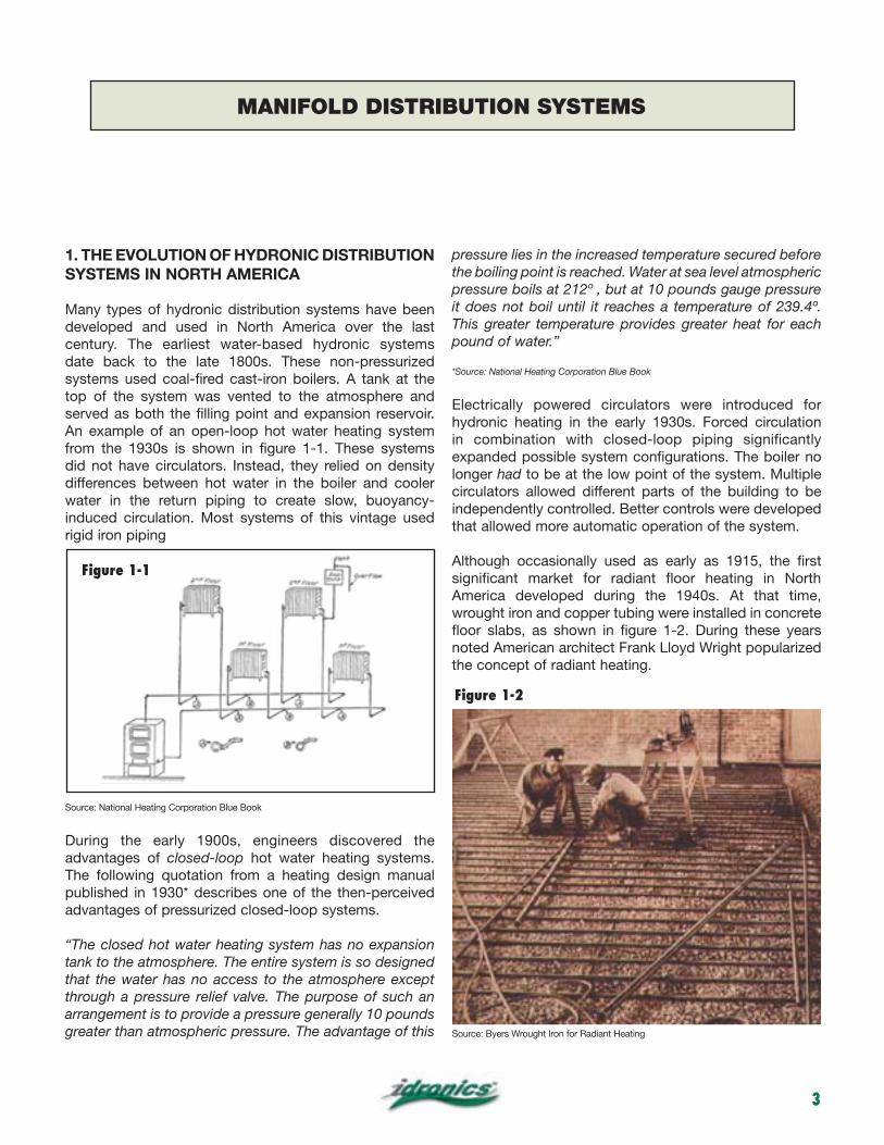
Many types of hydronic distribution systems have been developed and used in North America over the last century. The earliest water-based hydronic systems date back to the late 1800s. These non-pressurized systems used coal-fired cast-iron boilers. A tank at the top of the system was vented to the atmosphere and served as both the filling point and expansion reservoir. An example of an open-loop hot water heating system from the 1930s is shown in figure 1-1. These systems did not have circulators. Instead, they relied on density differences between hot water in the boiler and cooler water in the return piping to create slow, buoyancy-induced circulation. Most systems of this vintage used rigid iron piping
Source: National Heating Corporation Blue Book
During the early 1900s, engineers discovered the advantages of closed-loop hot water heating systems. The following quotation from a heating design manual published in 1930* describes one of the then-perceived advantages of pressurized closed-loop systems.
“The closed hot water heating system has no expansion tank to the atmosphere. The entire system is so designed that the water has no access to the atmosphere except through a pressure relief valve. The purpose of such an arrangement is to provide a pressure generally 10 pounds greater than atmospheric pressure. The advantage of this
pressure lies in the increased temperature secured before the boiling point is reached. Water at sea level atmospheric pressure boils at 212º , but at 10 pounds gauge pressure it does not boil until it reaches a temperature of 239.4º. This greater temperature provides greater heat for each pound of water.”
*Source: National Heating Corporation Blue Book
Electrically powered circulators were introduced for hydronic heating in the early 1930s. Forced circulation in combination with closed-loop piping significantly expanded possible system configurations. The boiler no longer had to be at the low point of the system. Multiple circulators allowed different parts of the building to be independently controlled. Better controls were developed that allowed more automatic operation of the system.
Although occasionally used as early as 1915, the first significant market for radiant floor heating in North America developed during the 1940s. At that time, wrought iron and copper tubing were installed in concrete floor slabs, as shown in figure 1-2. During these years noted American architect Frank Lloyd Wright popularized the concept of radiant heating.
Source: Byers Wrought Iron for Radiant Heating
MANIFOLD DISTRIBUTION SYSTEMS
Figure 1-1
Figure 1-2
4
The years following World War II brought rapid growth in all sectors of the construction market. This fueled the demand for better heating systems. The concept of centralheating was quickly establishing itself as preferable to the standard practice of tending multiple coal stoves or other types of area heaters located throughout a building.
Copper tubing steadily gained market share due to lower weight, resistance to corrosion, and relative ease of installation. It soon became the default piping material for residential and light commercial hydronic systems. Research at various universities investigated how copper tubing could be used for central home heating. Although some manifold-type distribution systems using 1/2” copper tubing as the supply and return to each radiator were studied in the early 1940s, so were alternative distribution concepts that favored reduced amount of piping and high operating temperatures in the interest of lowering cost. The following quotes from a 1942 trade publication* revealed the mindset of the time:
“Another promising innovation in the low cost field has been the connecting of several radiators or convectors in series. This is made possible by the positive head provided by the circulator, and in the future the idea may be used more extensively in larger homes.”
“The use of higher water temperatures, in the neighborhood of 240ºF gives greater heat output per square foot of surface, and permits the installation of smaller radiators and convectors.”
* Trends in Heating Development, published by Coal-Heat Magazine, July 1942
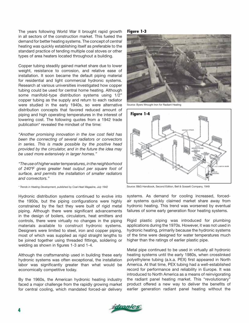
Hydronic distribution systems continued to evolve into the 1950s, but the piping configurations were highly constrained by the fact they were built of rigid metal piping. Although there were significant advancements in the design of boilers, circulators, heat emitters and controls, there were virtually no changes in the piping materials available to construct hydronic systems. Designers were limited to steel, iron and copper piping, most of which was supplied as rigid straight lengths to be joined together using threaded fittings, soldering or welding as shown in figures 1-3 and 1-4.
Although the craftsmanship used in building these early hydronic systems was often exceptional, the installation labor was significantly greater than what would be economically competitive today.
By the 1960s, the American hydronic heating industry faced a major challenge from the rapidly growing market for central cooling, which mandated forced-air delivery
systems. As demand for cooling increased, forced-air systems quickly claimed market share away from hydronic heating. This trend was worsened by eventual failures of some early generation floor heating systems.
Rigid plastic piping was introduced for plumbing applications during the 1970s. However, it was not used in hydronic heating, primarily because the hydronic systems of the time were designed for water temperatures much higher than the ratings of earlier plastic pipe.
Metal pipe continued to be used in virtually all hydronic heating systems until the early 1980s, when crosslinked polyethylene tubing (a.k.a. PEX) first appeared in North America. At that time, PEX tubing had a well-established record for performance and reliability in Europe. It was introduced to North America as a means of reinvigorating the radiant panel heating market. This “revolutionary” product offered a new way to deliver the benefits of earlier generation radiant panel heating without the
Source: Byers Wrought Iron for Radiant Heating
Source: B&G Handbook, Second Edition, Bell & Gossett Company, 1949
Figure 1-3
Figure 1-4
5
complications of joining metal pipe, or the concern over potential leaks from hundreds of joints that were literally cast in concrete.
PEX tubing, perhaps more than any other product over the last 25 years, enabled the North American hydronic heating industry to transition from decline to growth. Indeed, since 1990 the use of PEX tubing and similar products such as PEX-AL-PEX has driven the North American radiant panel heating market to grow by more than 2,000 percent!
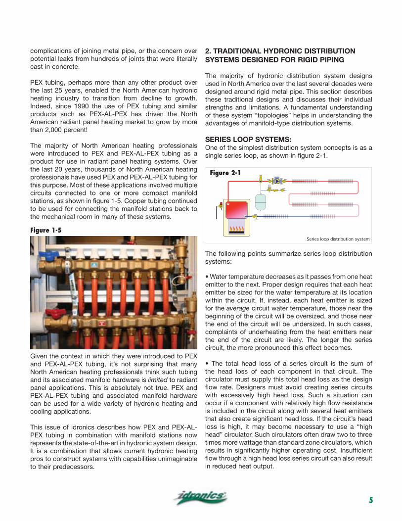
The majority of North American heating professionals were introduced to PEX and PEX-AL-PEX tubing as a product for use in radiant panel heating systems. Over the last 20 years, thousands of North American heating professionals have used PEX and PEX-AL-PEX tubing for this purpose. Most of these applications involved multiple circuits connected to one or more compact manifold stations, as shown in figure 1-5. Copper tubing continued to be used for connecting the manifold stations back to the mechanical room in many of these systems.
Given the context in which they were introduced to PEX and PEX-AL-PEX tubing, it’s not surprising that many North American heating professionals think such tubing and its associated manifold hardware is limited to radiant panel applications. This is absolutely not true. PEX and PEX-AL-PEX tubing and associated manifold hardware can be used for a wide variety of hydronic heating and cooling applications.
This issue of idronics describes how PEX and PEX-AL-PEX tubing in combination with manifold stations now represents the state-of-the-art in hydronic system design. It is a combination that allows current hydronic heating pros to construct systems with capabilities unimaginable to their predecessors.
2. TRADITIONAL HYDRONIC DISTRIBUTION SYSTEMS DESIGNED FOR RIGID PIPING
The majority of hydronic distribution system designs used in North America over the last several decades were designed around rigid metal pipe. This section describes these traditional designs and discusses their individual strengths and limitations. A fundamental understanding of these system “topologies” helps in understanding the advantages of manifold-type distribution systems.
SERIES LOOP SYSTEMS:One of the simplest distribution system concepts is as a single series loop, as shown in figure 2-1.
The following points summarize series loop distribution systems:
emitter to the next. Proper design requires that each heat emitter be sized for the water temperature at its location within the circuit. If, instead, each heat emitter is sized for the average circuit water temperature, those near the beginning of the circuit will be oversized, and those near the end of the circuit will be undersized. In such cases, complaints of underheating from the heat emitters near the end of the circuit are likely. The longer the series circuit, the more pronounced this effect becomes.
the head loss of each component in that circuit. The circulator must supply this total head loss as the design flow rate. Designers must avoid creating series circuits with excessively high head loss. Such a situation can occur if a component with relatively high flow resistance is included in the circuit along with several heat emitters that also create significant head loss. If the circuit’s head loss is high, it may become necessary to use a “high head” circulator. Such circulators often draw two to three times more wattage than standard zone circulators, which results in significantly higher operating cost. Insufficient flow through a high head loss series circuit can also result in reduced heat output.
Series loop distribution system
Figure 1-5
Figure 2-1
6
heat output. It is not possible to zone on a room-by-room basis using a series loop. Changing the flow rate or supply water temperature affects the heat output of all heat emitters on the loop. For this reason, all rooms served by a series circuit should be considered as a single zone. If some rooms experience significant internal heat gains and others do not, a series circuit should not be used. In general, series circuits are limited to relatively open floor plans where all areas are to be maintained at the same comfort level.
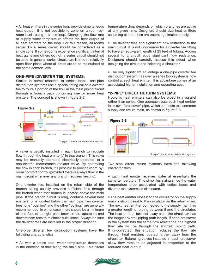
ONE-PIPE (DIVERTER TEE) SYSTEMS:Similar in some respects to series loops, one-pipe distribution systems use a special fitting called a divertertee to route a portion of the flow in the main piping circuit through a branch path containing one or more heat emitters. The concept is shown in figure 2-2.
A valve is usually installed in each branch to regulate flow through the heat emitter(s) in that branch. This valve may be manually operated, electrically operated, or a non-electric thermostatic radiator valve. By controlling the flow in each branch, it’s possible to provide room-by-room comfort control (provided there is always flow in the main circuit whenever any branch requires heating).
One diverter tee, installed on the return side of the branch piping usually provides sufficient flow through the branch when that branch is located above the main pipe. If the branch circuit is long, contains several heat emitters, or is located below the main pipe, two diverter tees, one “pushing” and the other “pulling,” are generally recommended. In either case, there should be a minimum of one foot of straight pipe between the upstream and downstream tees to minimize turbulence. Always be sure the diverter tees are installed in the proper direction.
One-pipe diverter tee distribution systems have the following characteristics:
in the direction of flow along the main pipe. This circuit
temperature drop depends on which branches are active at any given time. Designers should size heat emitters assuming all branches are operating simultaneously.
main circuit. It is not uncommon for a diverter tee fitting to have an equivalent length of 25 feet of tubing. Adding several to a circuit adds significant flow resistance. Designers should carefully assess this effect when designing the circuit and selecting a circulator.
distribution system has over a series loop system is flow control at each heat emitter. This advantage comes at an associated higher installation and operating cost.
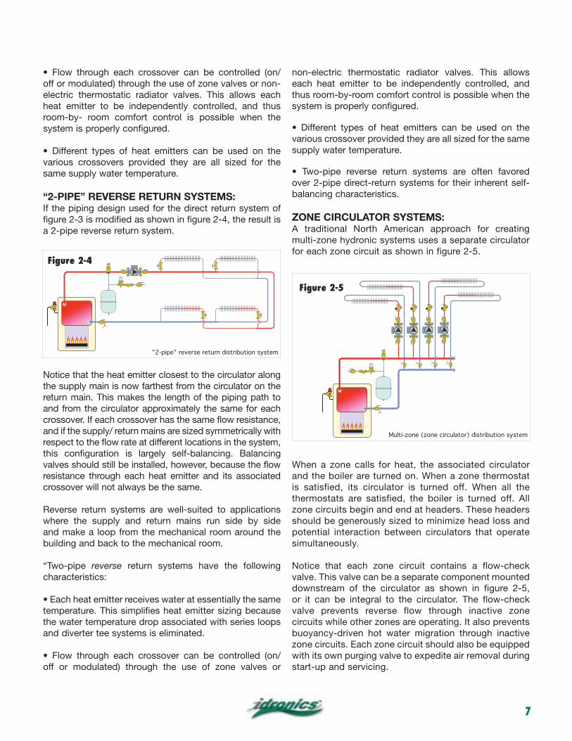
“2-PIPE” DIRECT RETURN SYSTEMS:Hydronic heat emitters can also be piped in a parallel rather than series. One approach puts each heat emitter in its own “crossover” pipe, which connects to a common supply and return main, as shown in figure 2-3.
Two-pipe direct return systems have the following characteristics:
same temperature. This simplifies sizing since the water temperature drop associated with series loops and diverter tee systems is eliminated.
main is also closest to the circulator on the return main. The next heat emitter connected to the supply main has a greater length of piping between it and the circulator. The heat emitter farthest away from the circulator has the longest overall piping path length. If each crossover in the system has the same flow resistance, the highest flow rate will be through the shortest piping path. If uncorrected, this situation reduces the flow rate through heat emitters located farther away from the circulator. Balancing valves installed in each crossover allow flow rates to be adjusted in proportion to the required heat output.
"1-pipe" diverter tee distribution system
diverter tee
diverter teediverter tee
diverter tee
diverter tee
"2-pipe" direct return distribution system
Figure 2-2
Figure 2-3
7
off or modulated) through the use of zone valves or non-electric thermostatic radiator valves. This allows each heat emitter to be independently controlled, and thus room-by- room comfort control is possible when the system is properly configured.
various crossovers provided they are all sized for the same supply water temperature.
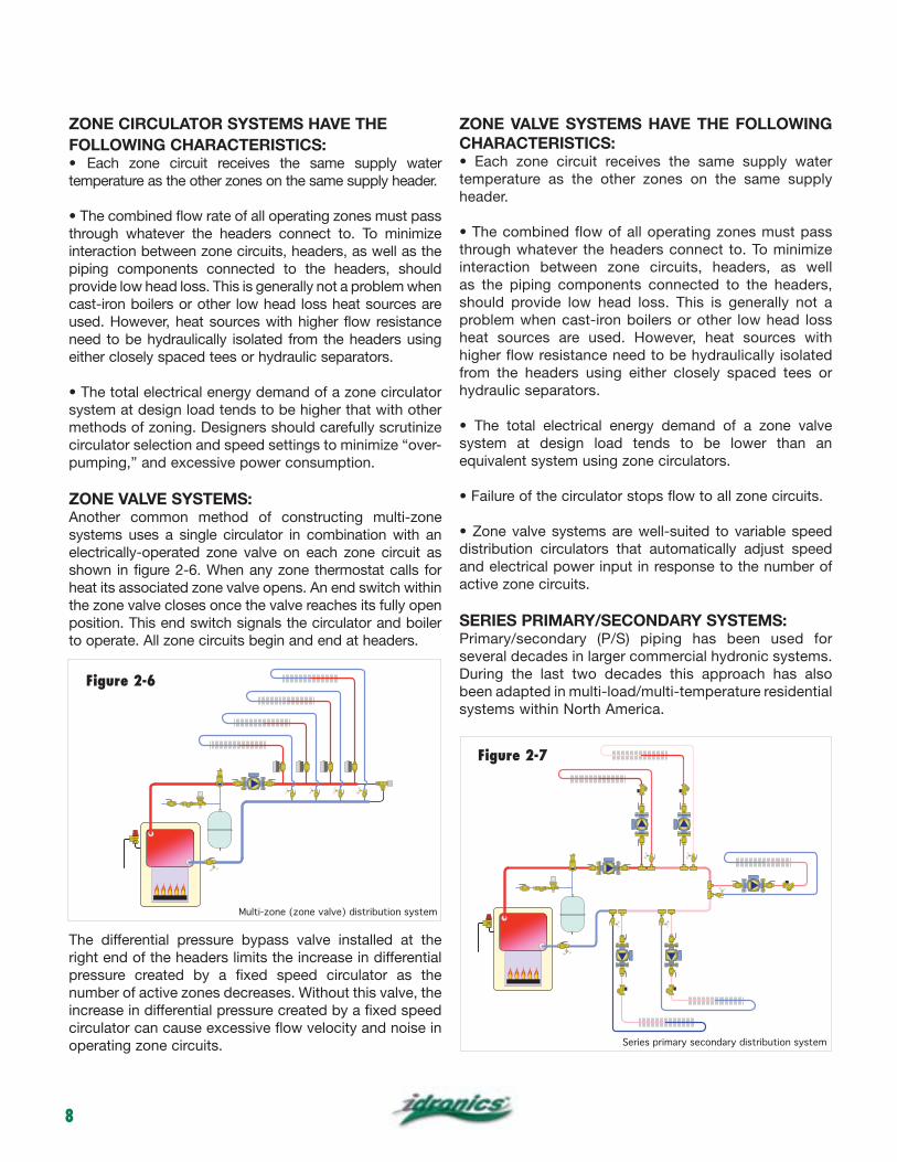
“2-PIPE” REVERSE RETURN SYSTEMS:If the piping design used for the direct return system of figure 2-3 is modified as shown in figure 2-4, the result is a 2-pipe reverse return system.
Notice that the heat emitter closest to the circulator along the supply main is now farthest from the circulator on the return main. This makes the length of the piping path to and from the circulator approximately the same for each crossover. If each crossover has the same flow resistance, and if the supply/ return mains are sized symmetrically with respect to the flow rate at different locations in the system, this configuration is largely self-balancing. Balancing valves should still be installed, however, because the flow resistance through each heat emitter and its associated crossover will not always be the same.
Reverse return systems are well-suited to applications where the supply and return mains run side by side and make a loop from the mechanical room around the building and back to the mechanical room.
“Two-pipe reverse return systems have the following characteristics:
temperature. This simplifies heat emitter sizing because the water temperature drop associated with series loops and diverter tee systems is eliminated.
off or modulated) through the use of zone valves or
non-electric thermostatic radiator valves. This allows each heat emitter to be independently controlled, and thus room-by-room comfort control is possible when the system is properly configured.
various crossover provided they are all sized for the same supply water temperature.
over 2-pipe direct-return systems for their inherent self-balancing characteristics.
ZONE CIRCULATOR SYSTEMS:A traditional North American approach for creating multi-zone hydronic systems uses a separate circulator for each zone circuit as shown in figure 2-5.
When a zone calls for heat, the associated circulator and the boiler are turned on. When a zone thermostat is satisfied, its circulator is turned off. When all the thermostats are satisfied, the boiler is turned off. All zone circuits begin and end at headers. These headers should be generously sized to minimize head loss and potential interaction between circulators that operate simultaneously.
Notice that each zone circuit contains a flow-check valve. This valve can be a separate component mounted downstream of the circulator as shown in figure 2-5, or it can be integral to the circulator. The flow-check valve prevents reverse flow through inactive zone circuits while other zones are operating. It also prevents buoyancy-driven hot water migration through inactive zone circuits. Each zone circuit should also be equipped with its own purging valve to expedite air removal during start-up and servicing.
"2-pipe" reverse return distribution system
Multi-zone (zone circulator) distribution system
Figure 2-4
Figure 2-5
8
ZONE CIRCULATOR SYSTEMS HAVE THEFOLLOWING CHARACTERISTICS:
temperature as the other zones on the same supply header.
through whatever the headers connect to. To minimize interaction between zone circuits, headers, as well as the piping components connected to the headers, should provide low head loss. This is generally not a problem when cast-iron boilers or other low head loss heat sources are used. However, heat sources with higher flow resistance need to be hydraulically isolated from the headers using either closely spaced tees or hydraulic separators.
system at design load tends to be higher that with other methods of zoning. Designers should carefully scrutinize circulator selection and speed settings to minimize “over-pumping,” and excessive power consumption.
ZONE VALVE SYSTEMS:Another common method of constructing multi-zone systems uses a single circulator in combination with an electrically-operated zone valve on each zone circuit as shown in figure 2-6. When any zone thermostat calls for heat its associated zone valve opens. An end switch within the zone valve closes once the valve reaches its fully open position. This end switch signals the circulator and boiler to operate. All zone circuits begin and end at headers.
The differential pressure bypass valve installed at the right end of the headers limits the increase in differential pressure created by a fixed speed circulator as the number of active zones decreases. Without this valve, the increase in differential pressure created by a fixed speed circulator can cause excessive flow velocity and noise in operating zone circuits.
ZONE VALVE SYSTEMS HAVE THE FOLLOWINGCHARACTERISTICS:
temperature as the other zones on the same supply header.
through whatever the headers connect to. To minimize interaction between zone circuits, headers, as well as the piping components connected to the headers, should provide low head loss. This is generally not a problem when cast-iron boilers or other low head loss heat sources are used. However, heat sources with higher flow resistance need to be hydraulically isolated from the headers using either closely spaced tees or hydraulic separators.
system at design load tends to be lower than an equivalent system using zone circulators.
distribution circulators that automatically adjust speed and electrical power input in response to the number of active zone circuits.
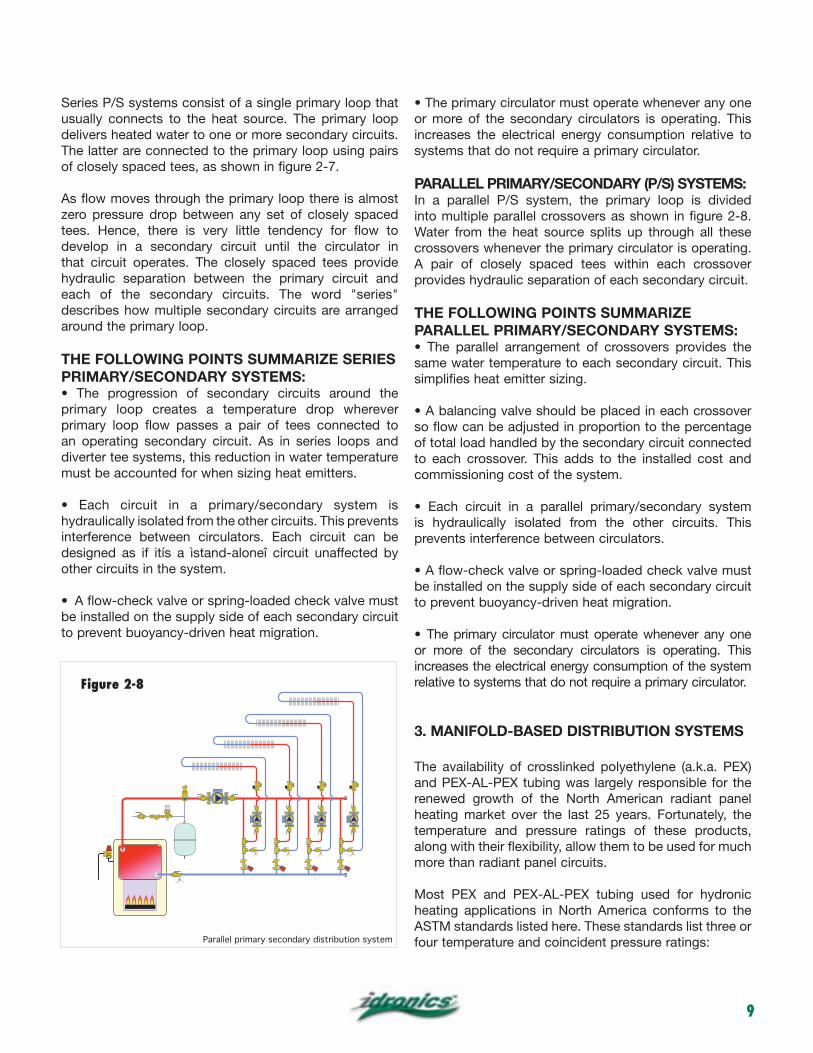
SERIES PRIMARY/SECONDARY SYSTEMS:Primary/secondary (P/S) piping has been used for several decades in larger commercial hydronic systems. During the last two decades this approach has also been adapted in multi-load/multi-temperature residential systems within North America.
Multi-zone (zone valve) distribution system
Series primary secondary distribution system
Figure 2-6
Figure 2-7
9
Series P/S systems consist of a single primary loop that usually connects to the heat source. The primary loop delivers heated water to one or more secondary circuits. The latter are connected to the primary loop using pairs of closely spaced tees, as shown in figure 2-7.
As flow moves through the primary loop there is almost zero pressure drop between any set of closely spaced tees. Hence, there is very little tendency for flow to develop in a secondary circuit until the circulator in that circuit operates. The closely spaced tees provide hydraulic separation between the primary circuit and each of the secondary circuits. The word "series" describes how multiple secondary circuits are arranged around the primary loop.
THE FOLLOWING POINTS SUMMARIZE SERIESPRIMARY/SECONDARY SYSTEMS:
primary loop creates a temperature drop wherever primary loop flow passes a pair of tees connected to an operating secondary circuit. As in series loops and diverter tee systems, this reduction in water temperature must be accounted for when sizing heat emitters.
hydraulically isolated from the other circuits. This prevents interference between circulators. Each circuit can be designed as if itís a ìstand-aloneî circuit unaffected by other circuits in the system.
be installed on the supply side of each secondary circuit to prevent buoyancy-driven heat migration.
or more of the secondary circulators is operating. This increases the electrical energy consumption relative to systems that do not require a primary circulator.
PARALLEL PRIMARY/SECONDARY (P/S) SYSTEMS:In a parallel P/S system, the primary loop is divided into multiple parallel crossovers as shown in figure 2-8. Water from the heat source splits up through all these crossovers whenever the primary circulator is operating. A pair of closely spaced tees within each crossover provides hydraulic separation of each secondary circuit.
THE FOLLOWING POINTS SUMMARIZEPARALLEL PRIMARY/SECONDARY SYSTEMS:
same water temperature to each secondary circuit. This simplifies heat emitter sizing.
so flow can be adjusted in proportion to the percentage of total load handled by the secondary circuit connected to each crossover. This adds to the installed cost and commissioning cost of the system.
is hydraulically isolated from the other circuits. This prevents interference between circulators.
be installed on the supply side of each secondary circuit to prevent buoyancy-driven heat migration.
or more of the secondary circulators is operating. This increases the electrical energy consumption of the system relative to systems that do not require a primary circulator.
3. MANIFOLD-BASED DISTRIBUTION SYSTEMS
The availability of crosslinked polyethylene (a.k.a. PEX) and PEX-AL-PEX tubing was largely responsible for the renewed growth of the North American radiant panel heating market over the last 25 years. Fortunately, the temperature and pressure ratings of these products, along with their flexibility, allow them to be used for much more than radiant panel circuits.
Most PEX and PEX-AL-PEX tubing used for hydronic heating applications in North America conforms to the ASTM standards listed here. These standards list three or four temperature and coincident pressure ratings:Parallel primary secondary distribution system
Figure 2-8
10
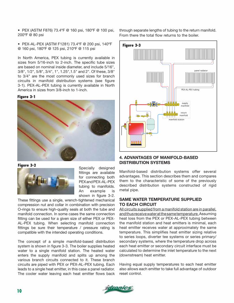
In North America, PEX tubing is currently available in sizes from 5/16-inch to 2-inch. The specific tube sizes are based on nominal inside diameter, and include 5/16", 3/8", 1/2", 5/8", 3/4", 1", 1.25",1.5" and 2". Of these, 3/8" to 3/4" are the most commonly used sizes for branch circuits in manifold distribution systems (see figure 3-1). PEX-AL-PEX tubing is currently available in North America in sizes from 3/8-inch to 1-inch.
Specially designed fittings are available for connecting both PEX and PEX-AL-PEX tubing to manifolds. An example is shown in figure 3-2.
These fittings use a single, wrench-tightened mechanical compression nut and collar in combination with precision O-rings to ensure high-quality seals at both the tube and manifold connection. In some cases the same connection fitting can be used for a given size of either PEX or PEX-AL-PEX tubing. When selecting manifold connection fittings be sure their temperature / pressure rating is compatible with the intended operating conditions.
The concept of a simple manifold-based distribution system is shown in figure 3-3. The boiler supplies heated water to a single manifold station. The heated water enters the supply manifold and splits up among the various branch circuits connected to it. These branch circuits are piped with PEX or PEX-AL-PEX tubing. Each leads to a single heat emitter, in this case a panel radiator. The cooler water leaving each heat emitter flows back
through separate lengths of tubing to the return manifold. From there the total flow returns to the boiler.
4. ADVANTAGES OF MANIFOLD-BASED DISTRIBUTION SYSTEMS
Manifold-based distribution systems offer several advantages. This section describes them and compares them to the characteristic of some of the previously described distribution systems constructed of rigid metal pipe.
SAME WATER TEMPERATURE SUPPLIEDTO EACH CIRCUITAll circuits supplied from a manifold station are in parallel, and thus receive water at the same temperature. Assuming heat loss from the PEX or PEX-AL-PEX tubing between the manifold station and heat emitters is minimal, each heat emitter receives water at approximately the same temperature. This simplifies heat emitter sizing relative to series loops, diverter tee systems or series primary/secondary systems, where the temperature drop across each heat emitter or secondary circuit interface must be calculated to determine the inlet temperature to the next (downstream) heat emitter.
Having equal supply temperatures to each heat emitter also allows each emitter to take full advantage of outdoor reset control.
PEX-AL-PEX tubing
supply
manifold
return
manifold
manifold station
panel radiator
Figure 3-1
Figure 3-2
Figure 3-3
11
ROOM-BY-ROOM COMFORT CONTROLWhen each heat emitter is served by its own circuit the heat output of that emitter can be regulated by varying the flow rate through it. This can be accomplished in a number of ways.
One approach is to turn the flow through the heat emitter on or off using a manually-operated valve, or more typically, an electrically operated valve. Zone valves, or manifold valve actuators operated by low-voltage ( 24 VAC) room thermostats are the most common type of controller in such systems.
Another method for regulating the heat output of each heat emitter is called modulating flow control. It differs from on/off control in that flow is fully adjustable from zero to some full design rate. Modulating flow control can be accomplished using electrically operated proportional valves at each heat emitter or proportional valve actuators mounted directly to some types of manifolds. The characteristic of this type of control will be covered in later sections.
ABILITY TO ADJUST FLOW IN EACH CIRCUITIn most manifold-based distribution systems the flow resistance of each circuit is different. This can be the result of different circuit lengths or tube sizes. It can also be caused by use of different heat emitters on the various circuits.
When such systems are commissioned, there’s no guarantee the flow through each circuit will deliver the proper heat output from each heat emitter. It’s often necessary to adjust the flow resistance of the circuits to accomplish this. That process is called “balancing.”
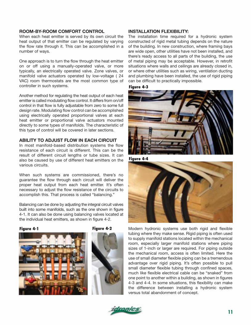
Balancing can be done by adjusting the integral circuit valves built into some manifolds, such as the one shown in figure 4-1. It can also be done using balancing valves located at the individual heat emitters, as shown in figure 4-2.
INSTALLATION FLEXIBILITY:The installation time required for a hydronic system constructed of rigid metal tubing depends on the nature of the building. In new construction, where framing bays are wide open, other utilities have not been installed, and there’s ready access to all parts of the building, the use of metal piping may be acceptable. However, in retrofit situations where walls and ceilings are already closed in, or where other utilities such as wiring, ventilation ducting and plumbing have been installed, the use of rigid piping can be difficult to practically impossible.
Modern hydronic systems use both rigid and flexible tubing where they make sense. Rigid piping is often used to supply manifold stations located within the mechanical room, especially larger manifold stations where piping sizes of 1-inch or larger are required. For piping outside the mechanical room, access is often limited. Here the use of small diameter flexible piping can be a tremendous advantage over rigid piping. It’s often possible to pull small diameter flexible tubing through confined spaces, much like flexible electrical cable can be “snaked” from one point to another within a building, as shown in figures 4-3 and 4-4. In some situations, this flexibility can make the difference between installing a hydronic system versus total abandonment of concept.
Figure 4-1 Figure 4-2
Figure 4-3
Figure 4-4
12
ADAPTABILITY TO VARIABLE SPEED PRESSURE-REGULATED CIRCULATORSAll manifold systems that use valves to regulate flow through branch circuits need a means of differential pressure control. It can be provided by a differential pressure bypass valve or use of a pressure-regulated circulator. The latter scenario is becoming increasingly popular as new ECM (Electronically Commutated Motor) circulators become available in North America. Such circulators are ideal for manifold-type distribution systems. They automatically control differential pressure and significantly reduce electrical power consumption under partial load conditions.
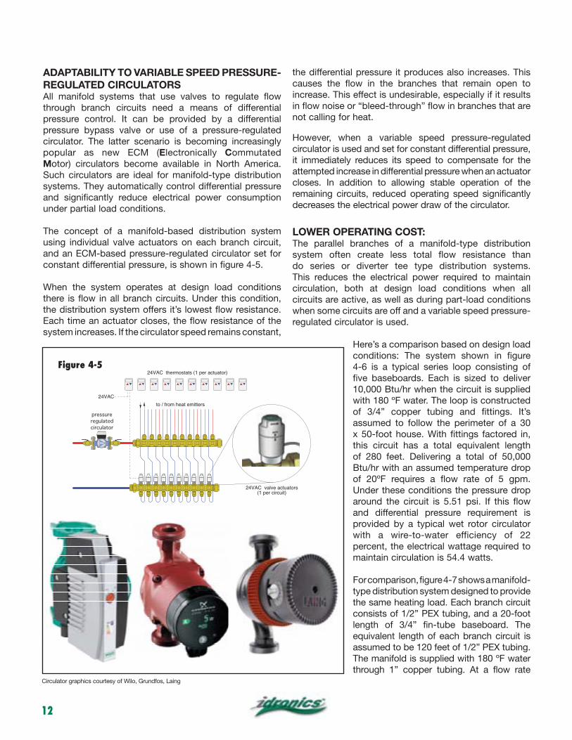
The concept of a manifold-based distribution system using individual valve actuators on each branch circuit, and an ECM-based pressure-regulated circulator set for constant differential pressure, is shown in figure 4-5.
When the system operates at design load conditions there is flow in all branch circuits. Under this condition, the distribution system offers it’s lowest flow resistance. Each time an actuator closes, the flow resistance of the system increases. If the circulator speed remains constant,
the differential pressure it produces also increases. This causes the flow in the branches that remain open to increase. This effect is undesirable, especially if it results in flow noise or “bleed-through” flow in branches that are not calling for heat.
However, when a variable speed pressure-regulated circulator is used and set for constant differential pressure, it immediately reduces its speed to compensate for the attempted increase in differential pressure when an actuator closes. In addition to allowing stable operation of the remaining circuits, reduced operating speed significantly decreases the electrical power draw of the circulator.
LOWER OPERATING COST:The parallel branches of a manifold-type distribution system often create less total flow resistance than do series or diverter tee type distribution systems. This reduces the electrical power required to maintain circulation, both at design load conditions when all circuits are active, as well as during part-load conditions when some circuits are off and a variable speed pressure-regulated circulator is used.
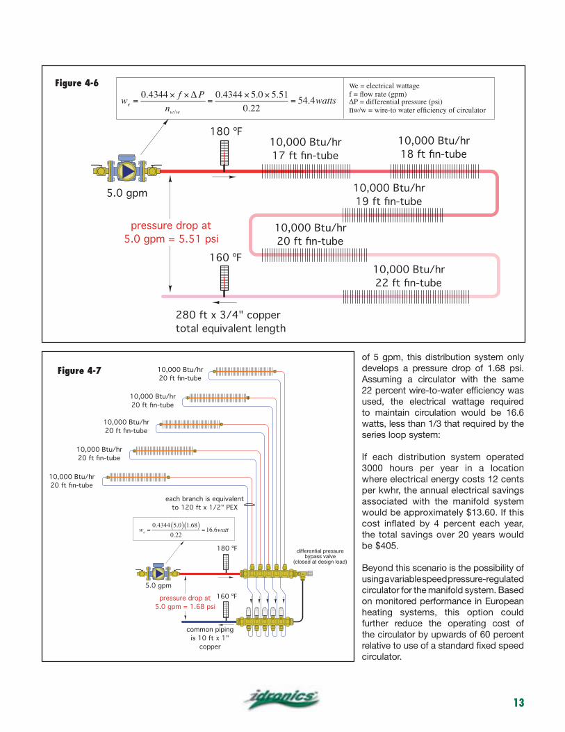
Here’s a comparison based on design load conditions: The system shown in figure 4-6 is a typical series loop consisting of five baseboards. Each is sized to deliver 10,000 Btu/hr when the circuit is supplied
of 3/4” copper tubing and fittings. It’s assumed to follow the perimeter of a 30 x 50-foot house. With fittings factored in, this circuit has a total equivalent length of 280 feet. Delivering a total of 50,000 Btu/hr with an assumed temperature drop
Under these conditions the pressure drop around the circuit is 5.51 psi. If this flow and differential pressure requirement is provided by a typical wet rotor circulator with a wire-to-water efficiency of 22 percent, the electrical wattage required to maintain circulation is 54.4 watts.
For comparison, figure 4-7 shows a manifold-type distribution system designed to provide the same heating load. Each branch circuit consists of 1/2” PEX tubing, and a 20-foot length of 3/4” fin-tube baseboard. The equivalent length of each branch circuit is assumed to be 120 feet of 1/2” PEX tubing.
through 1” copper tubing. At a flow rate
24VAC thermostats (1 per actuator)
24VAC
pressure
regulated
circulator
24VAC valve actuators(1 per circuit)
to / from heat emitters
Circulator graphics courtesy of Wilo, Grundfos, Laing
Figure 4-5
13
of 5 gpm, this distribution system only develops a pressure drop of 1.68 psi. Assuming a circulator with the same 22 percent wire-to-water efficiency was used, the electrical wattage required to maintain circulation would be 16.6 watts, less than 1/3 that required by the series loop system:
If each distribution system operated 3000 hours per year in a location where electrical energy costs 12 cents per kwhr, the annual electrical savings associated with the manifold system would be approximately $13.60. If this cost inflated by 4 percent each year, the total savings over 20 years would be $405.
Beyond this scenario is the possibility of using a variable speed pressure-regulated circulator for the manifold system. Based on monitored performance in European heating systems, this option could further reduce the operating cost of the circulator by upwards of 60 percent relative to use of a standard fixed speed circulator.
10,000 Btu/hr 10,000 Btu/hr
10,000 Btu/hr
10,000 Btu/hr
10,000 Btu/hr
180 ºF
160 ºF
5.0 gpm
we =0.4344 f P
nw/w
=0.4344 5.0 5.51
0.22= 54.4watts
we = electrical wattage
n
Figure 4-6
180 ºF
160 ºF
differential pressurebypass valve
(closed at design load)
10,000 Btu/hr
10,000 Btu/hr
10,000 Btu/hr
10,000 Btu/hr
10,000 Btu/hr
5.0 gpm
to 120 ft x 1/2" PEX
we =0.4344 5.0( ) 1.68( )
0.22=16.6watt
Figure 4-7
14
Manifold distribution systems also reduce electrical demand relative to primary/secondary systems since they do not require a primary circulator. If the primary circulator eliminated was assumed to operate at 80 watts for 3,000 hours per heating system in a location where electrical energy costs 12 cents per kwhr, the annual savings would be $28.80. If this cost was inflated at 4 percent per year for 20 years, the total savings associated would be about $858. Keep in mind that these amounts are based on the circulators used in small- to medium-size residential systems. Larger systems would have proportionally higher savings.
5. EXAMPLES OF MANIFOLD-BASED DISTRIBUTION SYSTEMS
The previously discussed advantages of manifold-based distribution systems hold true for a wide variety of systems. This section gives some examples of how manifold-based distribution systems can be applied with a wide variety of heat emitters.
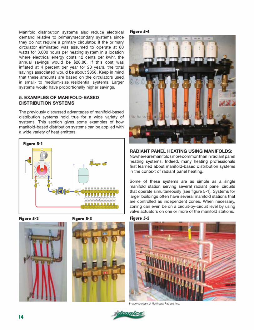
RADIANT PANEL HEATING USING MANIFOLDS:Nowhere are manifolds more common than in radiant panel heating systems. Indeed, many heating professionals first learned about manifold-based distribution systems in the context of radiant panel heating.
Some of these systems are as simple as a single manifold station serving several radiant panel circuits that operate simultaneously (see figure 5-1). Systems for larger buildings often have several manifold stations that are controlled as independent zones. When necessary, zoning can even be on a circuit-by-circuit level by using valve actuators on one or more of the manifold stations.
Figure 5-2 Figure 5-3
Figure 5-4
Figure 5-5
Image courtesy of Northeast Radiant, Inc.
VENT
Figure 5-1
15
The manifold stations used in radiant panel heating systems can vary from small two-circuit manifold stations that might serve a single room, to a large central manifold station in a commercial building. The hardware can be as simple as a T-drilled® copper header, to sophisticated assemblies with balancing valves, flow meters and temperature indicators for every circuit, as well as purging and isolating valves. Figures 5-2 through 5-5 show some of the variations used in manifold stations for radiant panel heating systems.
FIN-TUBE BASEBOARD SYSTEMSUSING MANIFOLDSFin-tube baseboard convectors, such as shown in figure 5-6, are very common in North American residential and light commercial hydronic systems. For decades, they have been installed using rigid copper pipe to connect several baseboards into a series loop, such as shown in figure 2-1. Although such traditional systems have worked, they do not provide the technical and economic advantages of manifold systems.
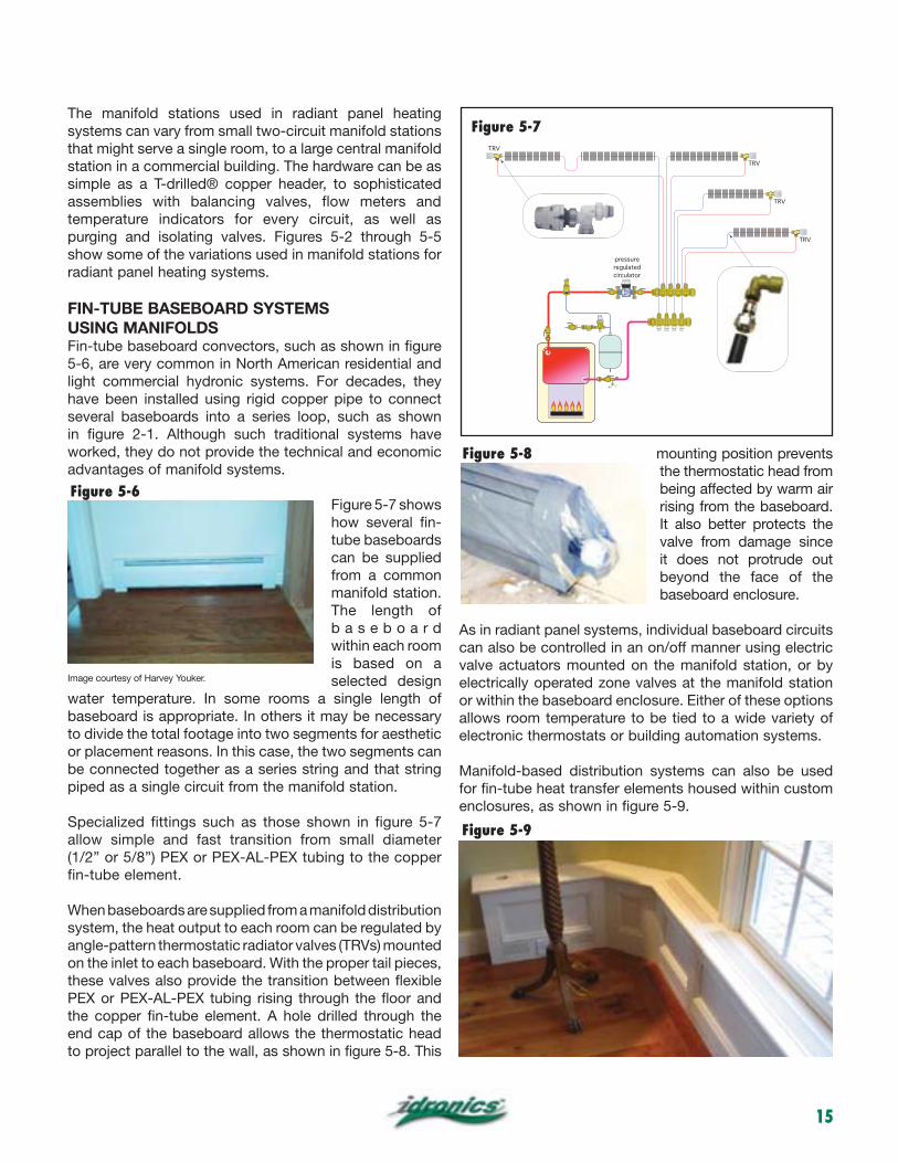
Figure 5-7 shows how several fin-tube baseboards can be supplied from a common manifold station. The length of b a s e b o a r d within each room is based on a selected design
water temperature. In some rooms a single length of baseboard is appropriate. In others it may be necessary to divide the total footage into two segments for aesthetic or placement reasons. In this case, the two segments can be connected together as a series string and that string piped as a single circuit from the manifold station.
Specialized fittings such as those shown in figure 5-7 allow simple and fast transition from small diameter (1/2” or 5/8”) PEX or PEX-AL-PEX tubing to the copper fin-tube element.
When baseboards are supplied from a manifold distribution system, the heat output to each room can be regulated by angle-pattern thermostatic radiator valves (TRVs) mounted on the inlet to each baseboard. With the proper tail pieces, these valves also provide the transition between flexible PEX or PEX-AL-PEX tubing rising through the floor and the copper fin-tube element. A hole drilled through the end cap of the baseboard allows the thermostatic head to project parallel to the wall, as shown in figure 5-8. This
mounting position prevents the thermostatic head from being affected by warm air rising from the baseboard. It also better protects the valve from damage since it does not protrude out beyond the face of the baseboard enclosure.
As in radiant panel systems, individual baseboard circuits can also be controlled in an on/off manner using electric valve actuators mounted on the manifold station, or by electrically operated zone valves at the manifold station or within the baseboard enclosure. Either of these options allows room temperature to be tied to a wide variety of electronic thermostats or building automation systems.
Manifold-based distribution systems can also be used for fin-tube heat transfer elements housed within custom enclosures, as shown in figure 5-9.
Figure 5-6
Figure 5-9
Figure 5-8
Image courtesy of Harvey Youker.
TRV
pressure
regulated
circulator
TRV
TRV
TRV
Figure 5-7
16
PANEL RADIATOR SYSTEMS USING MANIFOLDSPanel radiators are used extensively in residential and commercial hydronic systems in Europe, and are gaining in popularity in North America. These radiators are available in a wide variety of shapes and sizes. An example of a small panel radiator equipped with an integral thermostatic radiator valve is shown in figure 5-10. The two small white PEX-AL-PEX tubes at the bottom right of the radiator connect it to a manifold station.
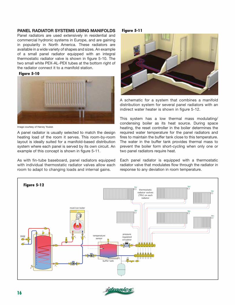
A panel radiator is usually selected to match the design heating load of the room it serves. This room-by-room layout is ideally suited for a manifold-based distribution system where each panel is served by its own circuit. An example of this concept is shown in figure 5-11.
As with fin-tube baseboard, panel radiators equipped with individual thermostatic radiator valves allow each room to adapt to changing loads and internal gains.
A schematic for a system that combines a manifold distribution system for several panel radiators with an indirect water heater is shown in figure 5-12.
This system has a low thermal mass modulating/condensing boiler as its heat source. During space heating, the reset controller in the boiler determines the required water temperature for the panel radiators and fires to maintain the buffer tank close to this temperature. The water in the buffer tank provides thermal mass to prevent the boiler form short-cycling when only one or two panel radiators require heat.
Each panel radiator is equipped with a thermostatic radiator valve that modulates flow through the radiator in response to any deviation in room temperature.
Figure 5-10
Figure 5-11
buffer tank
temperature
sensorDHW
mod/con boiler
thermostatic
radiator vavlves
(TRV) on each
radiator
pressure
regulated
circulator
TRV
TRV
TRV
TRV
TRV
TRV
VENT
Figure 5-12
Image courtesy of Harvey Youker.
17
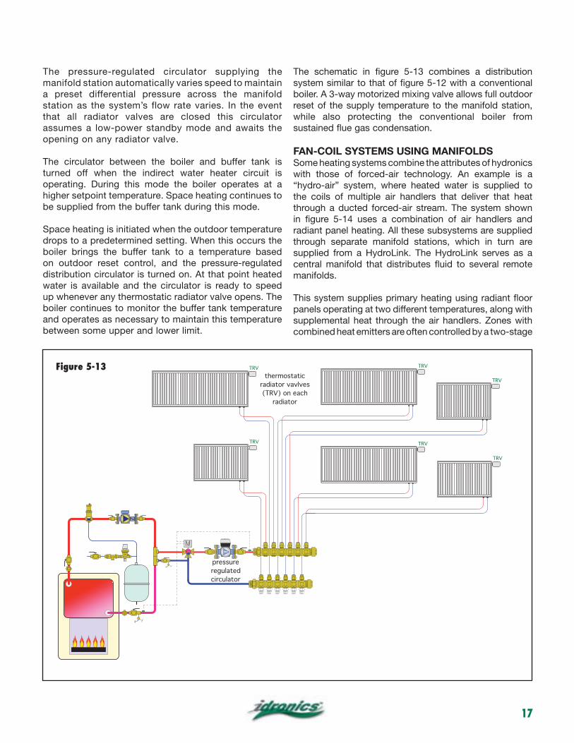
The pressure-regulated circulator supplying the manifold station automatically varies speed to maintain a preset differential pressure across the manifold station as the system’s flow rate varies. In the event that all radiator valves are closed this circulator assumes a low-power standby mode and awaits the opening on any radiator valve.
The circulator between the boiler and buffer tank is turned off when the indirect water heater circuit is operating. During this mode the boiler operates at a higher setpoint temperature. Space heating continues to be supplied from the buffer tank during this mode.
Space heating is initiated when the outdoor temperature drops to a predetermined setting. When this occurs the boiler brings the buffer tank to a temperature based on outdoor reset control, and the pressure-regulated distribution circulator is turned on. At that point heated water is available and the circulator is ready to speed up whenever any thermostatic radiator valve opens. The boiler continues to monitor the buffer tank temperature and operates as necessary to maintain this temperature between some upper and lower limit.
The schematic in figure 5-13 combines a distribution system similar to that of figure 5-12 with a conventional boiler. A 3-way motorized mixing valve allows full outdoor reset of the supply temperature to the manifold station, while also protecting the conventional boiler from sustained flue gas condensation.
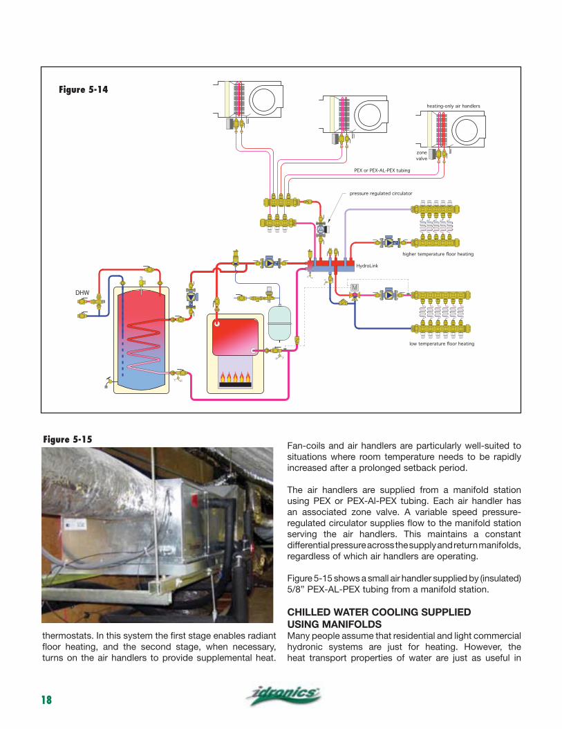
FAN-COIL SYSTEMS USING MANIFOLDSSome heating systems combine the attributes of hydronics with those of forced-air technology. An example is a “hydro-air” system, where heated water is supplied to the coils of multiple air handlers that deliver that heat through a ducted forced-air stream. The system shown in figure 5-14 uses a combination of air handlers and radiant panel heating. All these subsystems are supplied through separate manifold stations, which in turn are supplied from a HydroLink. The HydroLink serves as a central manifold that distributes fluid to several remote manifolds.
This system supplies primary heating using radiant floor panels operating at two different temperatures, along with supplemental heat through the air handlers. Zones with combined heat emitters are often controlled by a two-stage
thermostatic
radiator vavlves
(TRV) on each
radiator
pressure
regulated
circulator
TRV
TRV
TRV
TRV
TRV
TRVFigure 5-13
18
thermostats. In this system the first stage enables radiant floor heating, and the second stage, when necessary, turns on the air handlers to provide supplemental heat.
Fan-coils and air handlers are particularly well-suited to situations where room temperature needs to be rapidly increased after a prolonged setback period.
The air handlers are supplied from a manifold station using PEX or PEX-Al-PEX tubing. Each air handler has an associated zone valve. A variable speed pressure-regulated circulator supplies flow to the manifold station serving the air handlers. This maintains a constant differential pressure across the supply and return manifolds, regardless of which air handlers are operating.
Figure 5-15 shows a small air handler supplied by (insulated) 5/8” PEX-AL-PEX tubing from a manifold station.
CHILLED WATER COOLING SUPPLIEDUSING MANIFOLDSMany people assume that residential and light commercial hydronic systems are just for heating. However, the heat transport properties of water are just as useful in
DHW
valve
Figure 5-15
Figure 5-14
19
cooling applications. Chilled water cooling systems using manifold distribution systems provide several advantages over other methods of cooling. These include:
cooling zones as necessary without the complications associated with forced-air systems using motorized dampers.
building and supply those units using relatively small flexible tubing.
air handler in the event the air flow across the coil is lower than specified.
cooled condensers, geothermal water-to-water heat pumps, and small gas-fired absorption chillers.
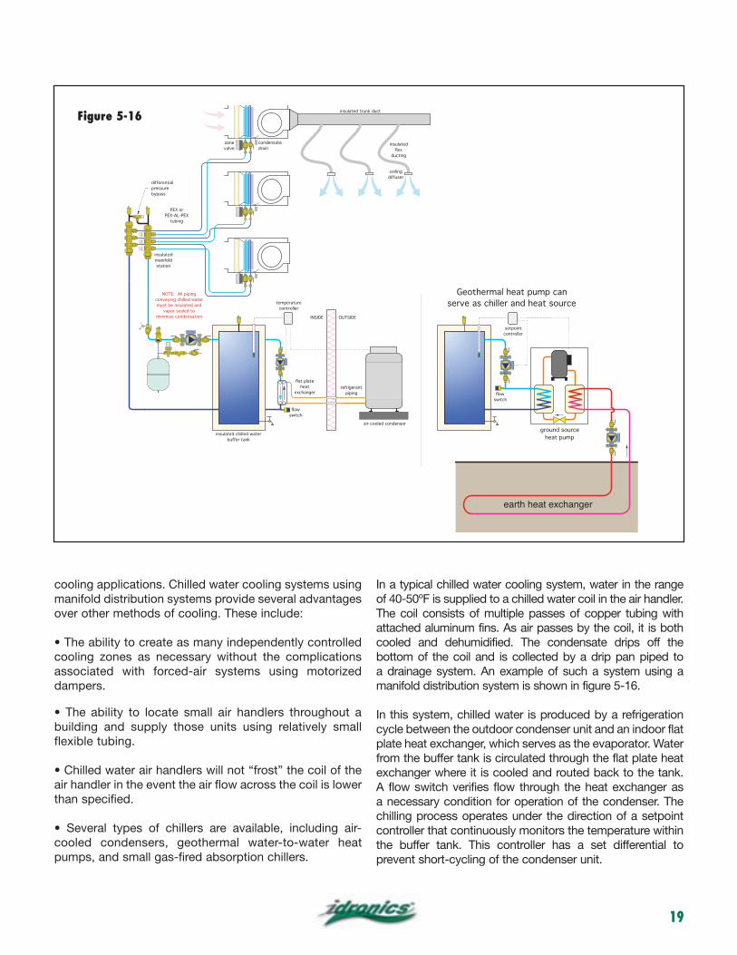
In a typical chilled water cooling system, water in the range
The coil consists of multiple passes of copper tubing with attached aluminum fins. As air passes by the coil, it is both cooled and dehumidified. The condensate drips off the bottom of the coil and is collected by a drip pan piped to a drainage system. An example of such a system using a manifold distribution system is shown in figure 5-16.
In this system, chilled water is produced by a refrigeration cycle between the outdoor condenser unit and an indoor flat plate heat exchanger, which serves as the evaporator. Water from the buffer tank is circulated through the flat plate heat exchanger where it is cooled and routed back to the tank. A flow switch verifies flow through the heat exchanger as a necessary condition for operation of the condenser. The chilling process operates under the direction of a setpoint controller that continuously monitors the temperature within the buffer tank. This controller has a set differential to prevent short-cycling of the condenser unit.
PEX or
PEX-AL-PEX
tubing
insulated trunk duct
insulated
ducting
ceiling
diffuser
air-cooled condensor
insulated chilled water
buffer tank
refrigerant
piping
INSIDE OUTSIDE
temperature
controller
condensate
drain
differential
pressure
bypass
insulated
manifold
station
zone
valve
NOTE: All piping
conveying chilled water
must be insulated and
vapor sealed to
minimize condensation
ground source
heat pump
earth heat exchanger
setpoint
controller
Geothermal heat pump can
serve as chiller and heat source
switch
switch
heat
Figure 5-16
20
When a zone thermostat calls for cooling, the blower in the associated air handler is turned on, and the zone valve for that air handler opens. The end switch in the zone valve signals the distribution circulator to operate, and chilled water is circulated through the coil in the air handler.
As in other manifold systems with valve-type circuit zoning, differential pressure must be regulated to provide stable and quiet system operation. In systems with a fixed speed distribution circulator, this can be done using a differential pressure bypass valve (see figure 5-16). An alternative is a variable speed pressure-regulated circulator, as discussed in previous heating applications.
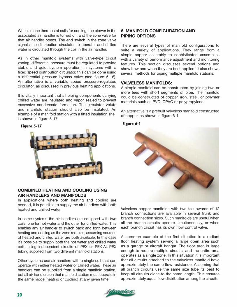
It is vitally important that all piping components carrying chilled water are insulated and vapor sealed to prevent excessive condensate formation. The circulator volute and manifold station should also be insulated. An example of a manifold station with a fitted insulation shell is shown in figure 5-17.
COMBINED HEATING AND COOLING USINGAIR HANDLERS AND MANIFOLDSIn applications where both heating and cooling are needed, it is possible to supply the air handlers with both heated and chilled water.
In some systems the air handlers are equipped with two coils: one for hot water and the other for chilled water. This enables any air handler to switch back and forth between heating and cooling as the zone requires, assuming sources of heated and chilled water are both available. In this case it’s possible to supply both the hot water and chilled water coils using independent circuits of PEX or PEX-AL-PEX tubing supplied from two different manifold stations.
Other systems use air handlers with a single coil that can operate with either heated water or chilled water. These air handlers can be supplied from a single manifold station, but all air handlers on that manifold station must operate in the same mode (heating or cooling) at any given time.
6. MANIFOLD CONFIGURATION AND PIPING OPTIONS
There are several types of manifold configurations to suite a variety of applications. They range from a simple copper assembly to sophisticated assemblies with a variety of performance adjustment and monitoring features. This section discusses several options and show how and when they are best applied. It also shows several methods for piping multiple manifold stations.
VALVELESS MANIFOLDS:A simple manifold can be constructed by joining two or more tees with short segments of pipe. The manifold could be constructed of copper, iron, steel, or polymer materials such as PVC, CPVC or polypropylene.
An alternative is a prebuilt valveless manifold constructed of copper, as shown in figure 6-1.
Valveless copper manifolds with two to upwards of 12 branch connections are available in several trunk and branch connection sizes. Such manifolds are useful when all the branch circuits operate simultaneously, or when each branch circuit has its own flow control valve.
A common example of the first situation is a radiant floor heating system serving a large open area such as a garage or aircraft hangar. The floor area is large enough to require multiple circuits, and the entire area operates as a single zone. In this situation it is important that all circuits attached to the valveless manifold have approximately the same flow resistance. Assuming that all branch circuits use the same size tube its best to keep all circuits close to the same length. This ensures approximately equal flow distribution among the circuits.
Figure 5-17 Figure 6-1
21
If circuits of significantly different lengths are attached to a valveless manifold, there will be significant differences in flow rate among them. The shorter the branch circuit, the greater its flow rate relative to the total flow entering the manifold. This can lead to inadequate heat delivery by some circuits, and surplus heat delivery in others.
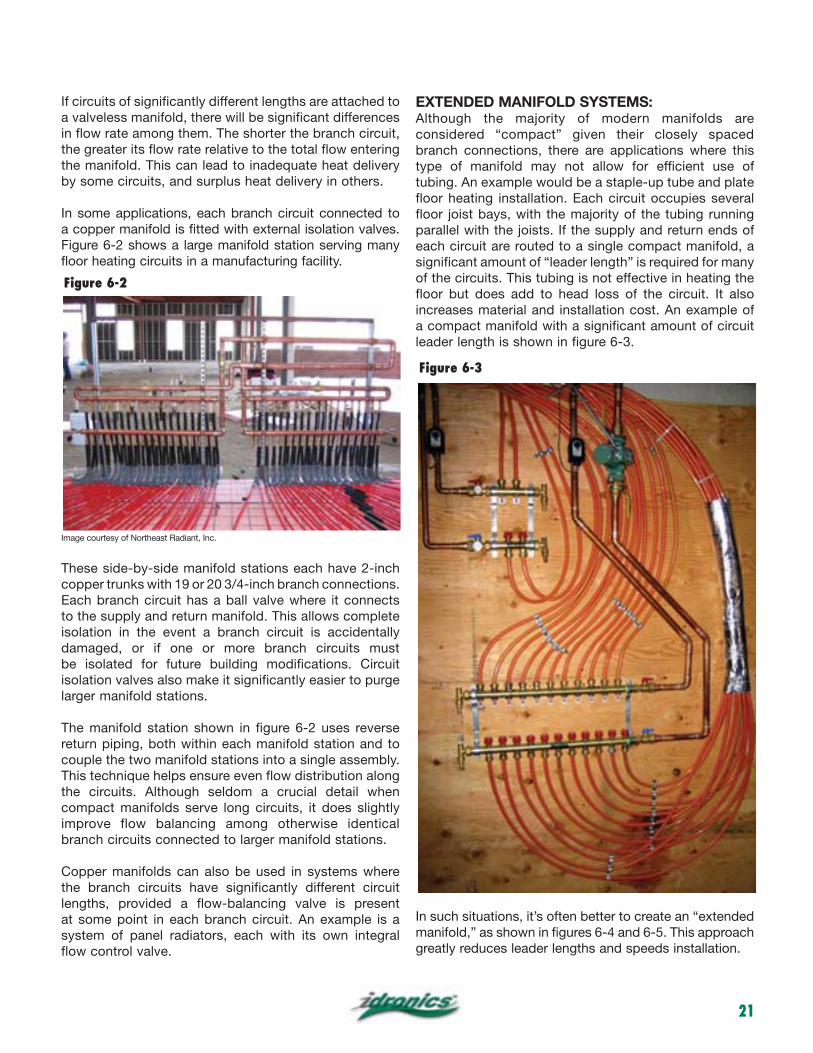
In some applications, each branch circuit connected to a copper manifold is fitted with external isolation valves. Figure 6-2 shows a large manifold station serving many floor heating circuits in a manufacturing facility.
Image courtesy of Northeast Radiant, Inc.
These side-by-side manifold stations each have 2-inch copper trunks with 19 or 20 3/4-inch branch connections. Each branch circuit has a ball valve where it connects to the supply and return manifold. This allows complete isolation in the event a branch circuit is accidentally damaged, or if one or more branch circuits must be isolated for future building modifications. Circuit isolation valves also make it significantly easier to purge larger manifold stations.
The manifold station shown in figure 6-2 uses reverse return piping, both within each manifold station and to couple the two manifold stations into a single assembly. This technique helps ensure even flow distribution along the circuits. Although seldom a crucial detail when compact manifolds serve long circuits, it does slightly improve flow balancing among otherwise identical branch circuits connected to larger manifold stations.
Copper manifolds can also be used in systems where the branch circuits have significantly different circuit lengths, provided a flow-balancing valve is present at some point in each branch circuit. An example is a system of panel radiators, each with its own integral flow control valve.
EXTENDED MANIFOLD SYSTEMS:Although the majority of modern manifolds are considered “compact” given their closely spaced branch connections, there are applications where this type of manifold may not allow for efficient use of tubing. An example would be a staple-up tube and plate floor heating installation. Each circuit occupies several floor joist bays, with the majority of the tubing running parallel with the joists. If the supply and return ends of each circuit are routed to a single compact manifold, a significant amount of “leader length” is required for many of the circuits. This tubing is not effective in heating the floor but does add to head loss of the circuit. It also increases material and installation cost. An example of a compact manifold with a significant amount of circuit leader length is shown in figure 6-3.
In such situations, it’s often better to create an “extended manifold,” as shown in figures 6-4 and 6-5. This approach greatly reduces leader lengths and speeds installation.
Figure 6-2
Figure 6-3

22
An extended manifold is usually built of copper tubing, with tees and isolation valves at both ends of each circuit. Other piping materials could also be used provided they match the temperature, pressure and other technical requirements of the application.
The circuit isolation valves allow for efficient filling and purging, as previously described.
When needed, zone valves could be added to control the flow through individual circuits.
Extended manifold systems can be direct return, reverse return or center feed. Center feeding, when possible, reduces flow rates in the manifolds and thus allows for small pipe sizes. Keeping the head loss along the length of an extended manifold low minimizes head loss and helps naturally balance the branch circuits. It is suggested that piping for an extended manifold be sized for flow velocities of approximately 2 feet per second when all circuits served by the manifold are operating at full design flow rate.
MANIFOLDS WITH INTEGRAL VALVESAlthough it’s possible to add external valves to so-called “valveless” manifolds, it’s not always the most efficient strategy in terms of time, cost and use of space in close confines. To address this, many manifolds are available with built-in valves. Some of these valves are well-suited to simple on/off flow control, while others are best when heat output will be regulated by varying the flow rate through a heat emitter.
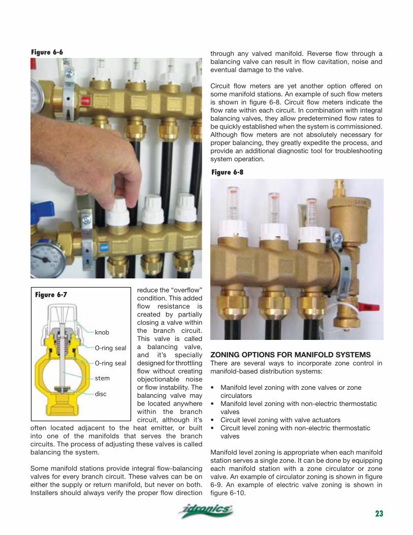
Some manifolds are available with integral valves intended to operate as either fully open or fully closed. These are referred to as isolation valves or shut-off valves. In normal service, these valves are fully open to provide a high Cv and very little flow resistance. If a circuit needs to be isolated for purging or service, the isolation valve would be fully closed using a knob. An example of a return manifold with integral isolation valves is shown in figure 6-6. A cross-section of the valve is shown in figure 6-7.
In some cases, isolation valves also allow for the attachment of an electric valve actuator. Because of their service requirements, these valves often use a flat disc to close off over the valve seat.
Because manifold stations often serve branch circuits with significantly different flow resistance, it’s unlikely that each branch circuit will automatically stabilize at its target flow rate when the system is first put into service. Instead, some of the circuits, those with flow rates higher than necessary, will require added flow resistance to
Figure 6-5
leader lengths back to manifold
with circuits routed to extended manifold
extended manifold, with valves at each end of circuits
Figure 6-4
23
reduce the “overflow” condition. This added flow resistance is created by partially closing a valve within the branch circuit. This valve is called a balancing valve, and it’s specially designed for throttling flow without creating objectionable noise or flow instability. The balancing valve may be located anywhere within the branch circuit, although it’s
often located adjacent to the heat emitter, or built into one of the manifolds that serves the branch circuits. The process of adjusting these valves is called balancing the system.
Some manifold stations provide integral flow-balancing valves for every branch circuit. These valves can be on either the supply or return manifold, but never on both. Installers should always verify the proper flow direction
through any valved manifold. Reverse flow through a balancing valve can result in flow cavitation, noise and eventual damage to the valve.
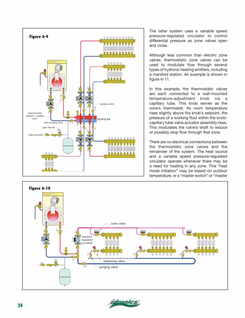
Circuit flow meters are yet another option offered on some manifold stations. An example of such flow meters is shown in figure 6-8. Circuit flow meters indicate the flow rate within each circuit. In combination with integral balancing valves, they allow predetermined flow rates to be quickly established when the system is commissioned. Although flow meters are not absolutely necessary for proper balancing, they greatly expedite the process, and provide an additional diagnostic tool for troubleshooting system operation.
ZONING OPTIONS FOR MANIFOLD SYSTEMSThere are several ways to incorporate zone control in manifold-based distribution systems:
circulators
valves
valves
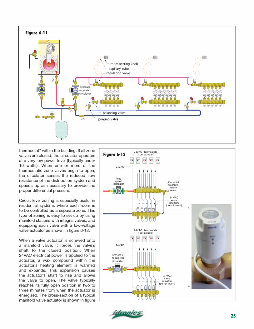
Manifold level zoning is appropriate when each manifold station serves a single zone. It can be done by equipping each manifold station with a zone circulator or zone valve. An example of circulator zoning is shown in figure 6-9. An example of electric valve zoning is shown in figure 6-10.
Figure 6-6
Figure 6-8
knob
stem
O-ring seal
O-ring seal
disc
Figure 6-7
24
The latter system uses a variable speed pressure-regulated circulator to control differential pressure as zone valves open and close.
Although less common than electric zone valves, thermostatic zone valves can be used to modulate flow through several types of hydronic heating emitters, including a manifold station. An example is shown in figure 6-11.
In this example, the thermostatic valves are each connected to a wall-mounted temperature-adjustment knob via a capillary tube. This knob serves as the zone’s thermostat. As room temperature rises slightly above the knob’s setpoint, the pressure of a working fluid within the knob-capillary tube-valve actuator assembly rises. This modulates the valve’s shaft to reduce or possibly stop flow through that zone.
There are no electrical connections between the thermostatic zone valves and the remainder of the system. The heat source and a variable speed pressure-regulated circulator operate whenever there may be a need for heating in any zone. This “heat mode initiation” may be based on outdoor temperature, or a “master switch” or “master
VENT
HydroLink
purging valves
boiler purging valve
make-up water
optional boiler
isolation / purging
valve
Figure 6-9
zone valve
balancing valve
purging valveVENT
pressure
regulated
circulator
Figure 6-10
25
thermostat” within the building. If all zone valves are closed, the circulator operates at a very low power level (typically under 10 watts). When one or more of the thermostatic zone valves begin to open, the circulator senses the reduced flow resistance of the distribution system and speeds up as necessary to provide the proper differential pressure.
Circuit level zoning is especially useful in residential systems where each room is to be controlled as a separate zone. This type of zoning is easy to set up by using manifold stations with integral valves, and equipping each valve with a low-voltage valve actuator as shown in figure 6-12.
When a valve actuator is screwed onto a manifold valve, it forces the valve’s shaft to the closed position. When 24VAC electrical power is applied to the actuator, a wax compound within the actuator’s heating element is warmed and expands. This expansion causes the actuator’s shaft to rise and allows the valve to open. The valve typically reaches its fully open position in two to three minutes from when the actuator is energized. The cross-section of a typical manifold valve actuator is shown in figure
differentialpressurebypassvalve
24 VACvalve
actuators(do not invert)
24VAC thermostats(1 per actuator)
24VAC
speedcirculator
24 VACvalve
actuators(do not invert)
24VAC thermostats(1 per actuator)
24VAC
pressure
regulated
circulator
balancing valve
purging valveVENT
pressure
regulated
circulator
purging valve
room setting knob
capillary tube
regulating valve
Figure 6-11
Figure 6-12
26
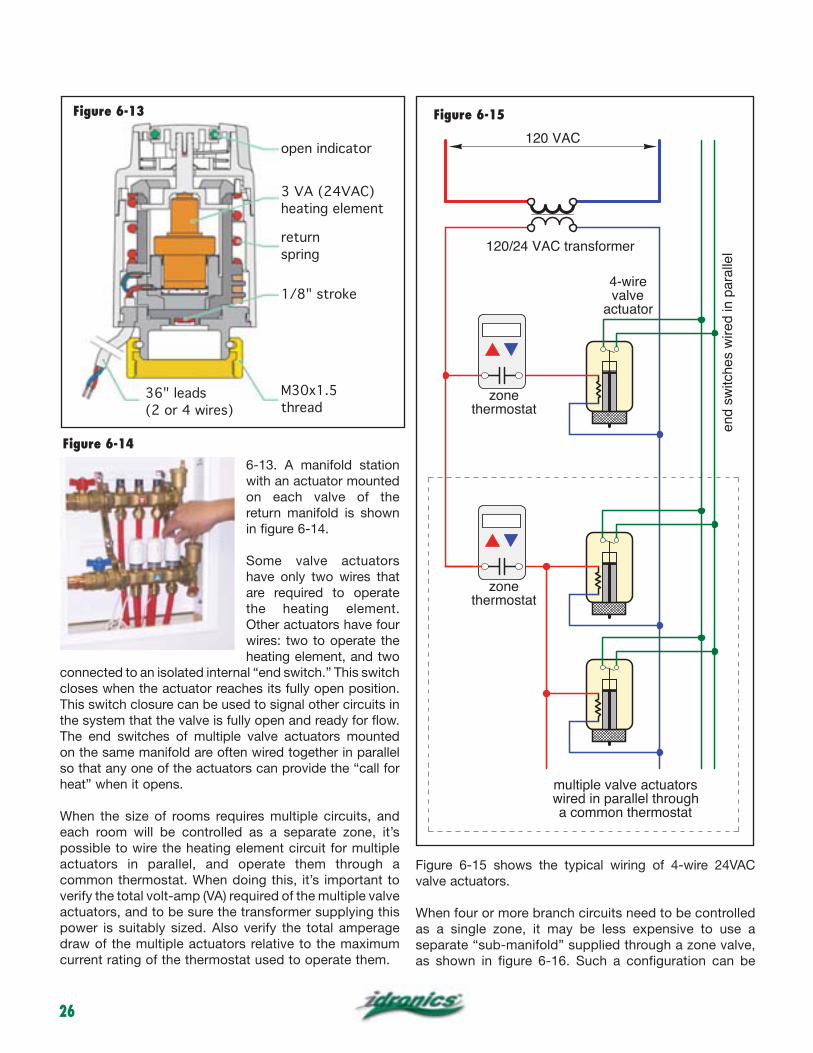
6-13. A manifold station with an actuator mounted on each valve of the return manifold is shown in figure 6-14.
Some valve actuators have only two wires that are required to operate the heating element. Other actuators have four wires: two to operate the heating element, and two
connected to an isolated internal “end switch.” This switch closes when the actuator reaches its fully open position. This switch closure can be used to signal other circuits in the system that the valve is fully open and ready for flow. The end switches of multiple valve actuators mounted on the same manifold are often wired together in parallel so that any one of the actuators can provide the “call for heat” when it opens.
When the size of rooms requires multiple circuits, and each room will be controlled as a separate zone, it’s possible to wire the heating element circuit for multiple actuators in parallel, and operate them through a common thermostat. When doing this, it’s important to verify the total volt-amp (VA) required of the multiple valve actuators, and to be sure the transformer supplying this power is suitably sized. Also verify the total amperage draw of the multiple actuators relative to the maximum current rating of the thermostat used to operate them.
Figure 6-15 shows the typical wiring of 4-wire 24VAC valve actuators.
When four or more branch circuits need to be controlled as a single zone, it may be less expensive to use a separate “sub-manifold” supplied through a zone valve, as shown in figure 6-16. Such a configuration can be
zonethermostat
4-wirevalve
actuator
120/24 VAC transformer
120 VAC
end
switc
hes
wire
d in
par
alle
l
multiple valve actuators wired in parallel through a common thermostat
zonethermostat
Figure 6-14
open indicator
3 VA (24VAC)
heating element
return
spring
1/8" stroke
M30x1.5
thread36" leads
(2 or 4 wires)
Figure 6-13 Figure 6-15
27
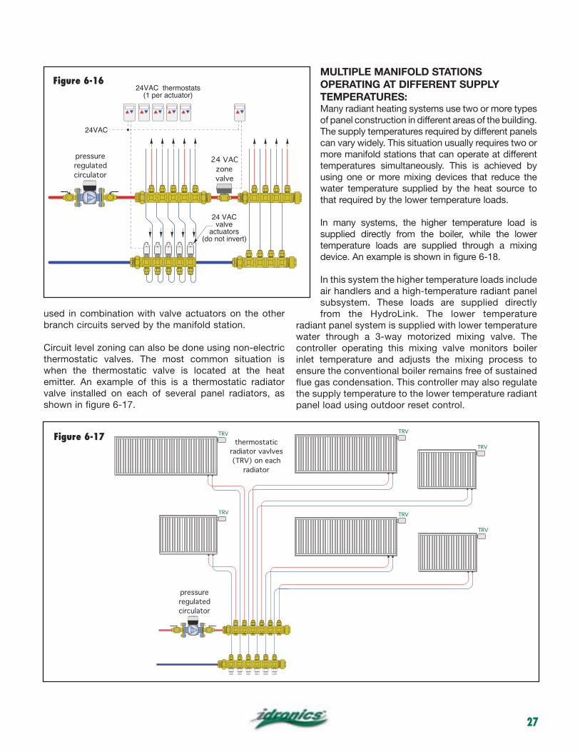
used in combination with valve actuators on the other branch circuits served by the manifold station.
Circuit level zoning can also be done using non-electric thermostatic valves. The most common situation is when the thermostatic valve is located at the heat emitter. An example of this is a thermostatic radiator valve installed on each of several panel radiators, as shown in figure 6-17.
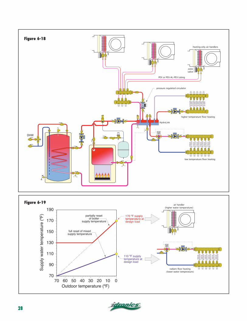
MULTIPLE MANIFOLD STATIONSOPERATING AT DIFFERENT SUPPLYTEMPERATURES:Many radiant heating systems use two or more types of panel construction in different areas of the building. The supply temperatures required by different panels can vary widely. This situation usually requires two or more manifold stations that can operate at different temperatures simultaneously. This is achieved by using one or more mixing devices that reduce the water temperature supplied by the heat source to that required by the lower temperature loads.
In many systems, the higher temperature load is supplied directly from the boiler, while the lower temperature loads are supplied through a mixing device. An example is shown in figure 6-18.
In this system the higher temperature loads include air handlers and a high-temperature radiant panel subsystem. These loads are supplied directly from the HydroLink. The lower temperature
radiant panel system is supplied with lower temperature water through a 3-way motorized mixing valve. The controller operating this mixing valve monitors boiler inlet temperature and adjusts the mixing process to ensure the conventional boiler remains free of sustained flue gas condensation. This controller may also regulate the supply temperature to the lower temperature radiant panel load using outdoor reset control.
thermostatic
radiator vavlves
(TRV) on each
radiator
pressure
regulated
circulator
TRV
TRV
TRV
TRV
TRV
TRV
24VAC thermostats(1 per actuator)
24VAC
pressure
regulated
circulator
24 VAC
zone
valve
24 VACvalve
actuators(do not invert)
Figure 6-16
Figure 6-17
28
DHW
valve
Sup
ply
wat
er te
mpe
ratu
re (
ºF)
Outdoor temperature (ºF)
70
90
110
130
150
170
190
70 60 50 40 30 20 10 0
partially resetof boiler
supply temperature
110 ºF supplytemperature atdesign load
170 ºF supplytemperature atdesign load
full reset of mixedsupply temperature
Figure 6-18
Figure 6-19
29
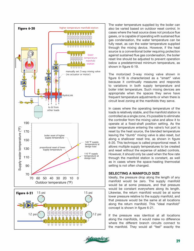
The water temperature supplied by the boiler can also be varied based on outdoor reset control. In cases where the heat source does not produce flue gases, or is capable of operating with sustained flue gas condensation, the water temperature can be fully reset, as can the water temperature supplied through the mixing device. However, if the heat source is a conventional boiler requiring protection against sustained flue gas condensation, the boiler reset line should be adjusted to prevent operation below a predetermined minimum temperature, as shown in figure 6-19.
The motorized 3-way mixing valve shown in figure 6-18 is characterized as a “smart” valve because it continually measures and responds to variations in both supply temperature and boiler inlet temperature. Such mixing devices are appropriate when the spaces they serve have frequent temperature adjustments or when there is circuit level zoning at the manifolds they serve.
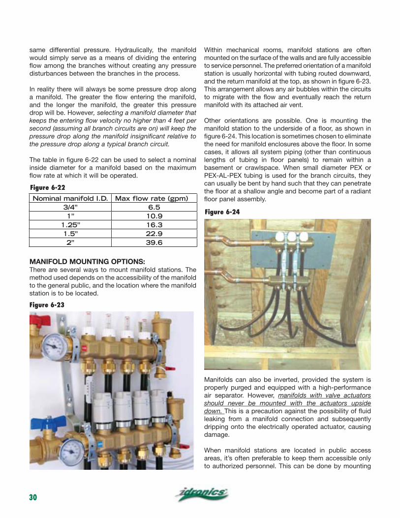
In cases where the operating temperature of the loads is relatively stable, and the manifold station is controlled as a single zone, it’s possible to eliminate the controller from the mixing valve and allow it to operate at a fixed-shaft position setting. As the water temperature entering the valve’s hot port is reset by the heat source, the blended temperature leaving the “dumb” mixing valve is also reset, but along a shallower reset line, as shown in figure 6-20. This technique is called proportional reset. It allows multiple supply temperatures to be created and reset without the expense of added controls. However, it should only be used when the flow rate through the manifold station is constant, as well as in cases where the space-heating thermostat setting is not often changed.
SELECTING A MANIFOLD SIZEIdeally, the pressure drop along the length of any manifold would be zero. The supply manifold would be at some pressure, and that pressure would be constant everywhere along its length. Likewise, the return manifold would be at some lower pressure relative to the supply manifold, and that pressure would be the same at all locations along the return manifold. This “ideal manifold” concept is shown in figure 6-21.
If the pressure was identical at all locations along the manifolds, it would make no difference where the different branch circuits connect to the manifold. They would all “feel” exactly the
Sup
ply
wat
er te
mpe
ratu
re (
ºF)
Outdoor temperature (ºF)
70
90
110
130
150
170
190
70 60 50 40 30 20 10 0
110 ºF supplytemperature atdesign load
140 ºF supplytemperature atdesign loadproportional reset of lower
supply temperature
boiler reset of highersupply temperature
VENT
HydroLink
lower
temperature
manifold
station
higher temperature manifold station
manually set 3-way mixing valve
(no actuator or motor)
to & from
other loads
15 psi 15 psi
12 psi 12 psi
Figure 6-20
Figure 6-21
30
same differential pressure. Hydraulically, the manifold would simply serve as a means of dividing the entering flow among the branches without creating any pressure disturbances between the branches in the process.
In reality there will always be some pressure drop along a manifold. The greater the flow entering the manifold, and the longer the manifold, the greater this pressure drop will be. However, selecting a manifold diameter that keeps the entering flow velocity no higher than 4 feet per second (assuming all branch circuits are on) will keep the pressure drop along the manifold insignificant relative to the pressure drop along a typical branch circuit.
The table in figure 6-22 can be used to select a nominal inside diameter for a manifold based on the maximum flow rate at which it will be operated.
MANIFOLD MOUNTING OPTIONS:There are several ways to mount manifold stations. The method used depends on the accessibility of the manifold to the general public, and the location where the manifold station is to be located.
Within mechanical rooms, manifold stations are often mounted on the surface of the walls and are fully accessible to service personnel. The preferred orientation of a manifold station is usually horizontal with tubing routed downward, and the return manifold at the top, as shown in figure 6-23. This arrangement allows any air bubbles within the circuits to migrate with the flow and eventually reach the return manifold with its attached air vent.
Other orientations are possible. One is mounting the manifold station to the underside of a floor, as shown in figure 6-24. This location is sometimes chosen to eliminate the need for manifold enclosures above the floor. In some cases, it allows all system piping (other than continuous lengths of tubing in floor panels) to remain within a basement or crawlspace. When small diameter PEX or PEX-AL-PEX tubing is used for the branch circuits, they can usually be bent by hand such that they can penetrate the floor at a shallow angle and become part of a radiant floor panel assembly.
Manifolds can also be inverted, provided the system is properly purged and equipped with a high-performance air separator. However, manifolds with valve actuators should never be mounted with the actuators upside down. This is a precaution against the possibility of fluid leaking from a manifold connection and subsequently dripping onto the electrically operated actuator, causing damage.
When manifold stations are located in public access areas, it’s often preferable to keep them accessible only to authorized personnel. This can be done by mounting
Figure 6-22
Nominal manifold I.D. Max flow rate (gpm)3/4” 6.51” 10.9
1.25” 16.31.5” 22.92” 39.6
Figure 6-23
Figure 6-24
31
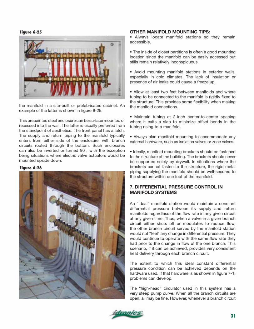
the manifold in a site-built or prefabricated cabinet. An example of the latter is shown in figure 6-25.
This prepainted steel enclosure can be surface mounted or recessed into the wall. The latter is usually preferred from the standpoint of aesthetics. The front panel has a latch. The supply and return piping to the manifold typically enters from either side of the enclosure, with branch circuits routed through the bottom. Such enclosures
being situations where electric valve actuators would be mounted upside down.
OTHER MANIFOLD MOUNTING TIPS:
accessible.
location since the manifold can be easily accessed but stills remain relatively inconspicuous.
especially in cold climates. The lack of insulation or presence of air leaks could cause a freeze up.
tubing to be connected to the manifold is rigidly fixed to the structure. This provides some flexibility when making the manifold connections.
where it exits a slab to minimize offset bends in the tubing rising to a manifold.
external hardware, such as isolation valves or zone valves.
to the structure of the building. The brackets should never be supported solely by drywall. In situations where the brackets cannot fasten to the structure, the rigid metal piping supplying the manifold should be well-secured to the structure within one foot of the manifold.
7. DIFFERENTIAL PRESSURE CONTROL IN MANIFOLD SYSTEMS
An “ideal” manifold station would maintain a constant differential pressure between its supply and return manifolds regardless of the flow rate in any given circuit at any given time. Thus, when a valve in a given branch circuit either shuts off or modulates to reduce flow, the other branch circuit served by the manifold station would not “feel” any change in differential pressure. They would continue to operate with the same flow rate they had prior to the change in flow of the one branch. This scenario, if it can be achieved, provides very consistent heat delivery through each branch circuit.
The extent to which this ideal constant differential pressure condition can be achieved depends on the hardware used. If that hardware is as shown in figure 7-1, problems can develop.
The “high-head” circulator used in this system has a very steep pump curve. When all the branch circuits are open, all may be fine. However, whenever a branch circuit
Figure 6-26
Figure 6-25
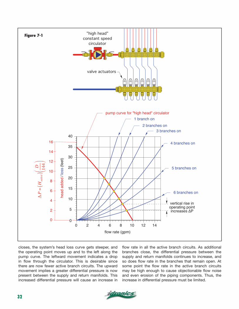
32
closes, the system’s head loss curve gets steeper, and the operating point moves up and to the left along the pump curve. The leftward movement indicates a drop in flow through the circulator. This is desirable since there are now fewer active branch circuits. The upward movement implies a greater differential pressure is now present between the supply and return manifolds. This increased differential pressure will cause an increase in
flow rate in all the active branch circuits. As additional branches close, the differential pressure between the supply and return manifolds continues to increase, and so does flow rate in the branches that remain open. At some point the flow rate in the active branch circuits may be high enough to cause objectionable flow noise and even erosion of the piping components. Thus, the increase in differential pressure must be limited.
0 2 4 6 8 10 12 14
P
"high head"
constant speed
circulator
valve actuators
5
10
15
20
25
30
35
40
00
8
6
4
2
0
10
12
14
16
P=H
added
()
D 144
Figure 7-1
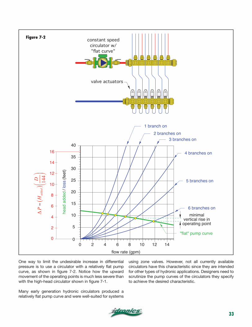
33
One way to limit the undesirable increase in differential pressure is to use a circulator with a relatively flat pump curve, as shown in figure 7-2. Notice how the upward movement of the operating points is much less severe than with the high-head circulator shown in figure 7-1.
Many early generation hydronic circulators produced a relatively flat pump curve and were well-suited for systems
using zone valves. However, not all currently available circulators have this characteristic since they are intended for other types of hydronic applications. Designers need to scrutinize the pump curves of the circulators they specify to achieve the desired characteristic.
2 4 6 8 10 12 14
constant speed
circulator w/
5
10
15
20
25
30
35
40
00
8
6
4
2
0
10
12
14
16
P=H
added
()
D 144
Figure 7-2
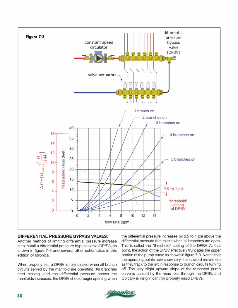
34
DIFFERENTIAL PRESSURE BYPASS VALVES:Another method of limiting differential pressure increase is to install a differential pressure bypass valve (DPBV), as shown in figure 7-3 and several other schematics in this edition of idronics.
When properly set, a DPBV is fully closed when all branch circuits served by the manifold are operating. As branches start closing, and the differential pressure across the manifolds increases, the DPBV should begin opening when
the differential pressure increases by 0.5 to 1 psi above the differential pressure that exists when all branches are open. This is called the “threshold” setting of the DPBV. At that point, the action of the DPBV effectively truncates the upper portion of the pump curve as shown in figure 7-3. Notice that the operating points now show very little upward movement as they track to the left in response to branch circuits turning off. The very slight upward slope of the truncated pump curve is caused by the head loss through the DPBV, and typically is insignificant for properly sized DPBVs.
constant speed
circulator
valve actuators
differential
pressure
bypass
valve
(DPBV)
2 4 6 8 10 12 14
0.5 to 1 psi
5
10
15
20
25
30
35
40
00
8
6
4
2
0
10
12
14
16
P=H
added
()
D 144
Figure 7-3
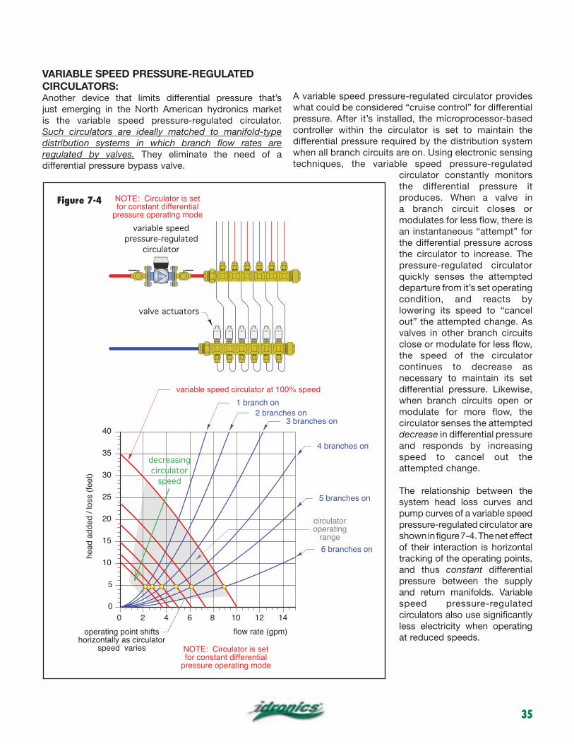
35
VARIABLE SPEED PRESSURE-REGULATEDCIRCULATORS:Another device that limits differential pressure that’s just emerging in the North American hydronics market is the variable speed pressure-regulated circulator. Such circulators are ideally matched to manifold-type distribution systems in which branch flow rates are regulated by valves. They eliminate the need of a differential pressure bypass valve.
A variable speed pressure-regulated circulator provides what could be considered “cruise control” for differential pressure. After it’s installed, the microprocessor-based controller within the circulator is set to maintain the differential pressure required by the distribution system when all branch circuits are on. Using electronic sensing techniques, the variable speed pressure-regulated
circulator constantly monitors the differential pressure it produces. When a valve in a branch circuit closes or modulates for less flow, there is an instantaneous “attempt” for the differential pressure across the circulator to increase. The pressure-regulated circulator quickly senses the attempted departure from it’s set operating condition, and reacts by lowering its speed to “cancel out” the attempted change. As valves in other branch circuits close or modulate for less flow, the speed of the circulator continues to decrease as necessary to maintain its set differential pressure. Likewise, when branch circuits open or modulate for more flow, the circulator senses the attempted decrease in differential pressure and responds by increasing speed to cancel out the attempted change.
The relationship between the system head loss curves and pump curves of a variable speed pressure-regulated circulator are shown in figure 7-4. The net effect of their interaction is horizontal tracking of the operating points, and thus constant differential pressure between the supply and return manifolds. Variable speed pressure-regulated circulators also use significantly less electricity when operating at reduced speeds.
operating point shifts horizontally as circulator
speed varies
variable speed
pressure-regulated
circulator
valve actuators
NOTE: Circulator is set for constant differential
pressure operating mode
NOTE: Circulator is set for constant differential
pressure operating mode
0
5
10
15
20
25
30
35
40
0 2 4 6 8 10 12 14
variable speed circulator at 100% speed
1 branch on2 branches on
3 branches on
4 branches on
5 branches on
6 branches on
decreasing
circulator
speed
circulatoroperating
range
Figure 7-4
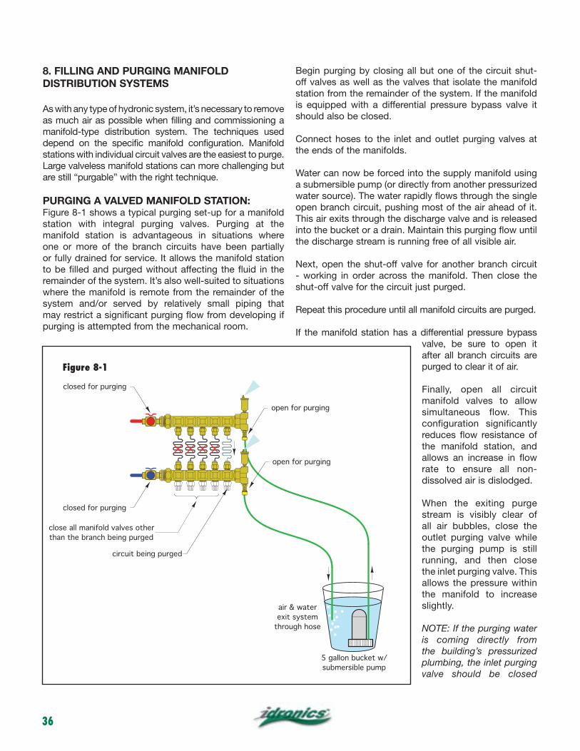
36
8. FILLING AND PURGING MANIFOLD DISTRIBUTION SYSTEMS
As with any type of hydronic system, it’s necessary to remove as much air as possible when filling and commissioning a manifold-type distribution system. The techniques used depend on the specific manifold configuration. Manifold stations with individual circuit valves are the easiest to purge. Large valveless manifold stations can more challenging but are still “purgable” with the right technique.
PURGING A VALVED MANIFOLD STATION:Figure 8-1 shows a typical purging set-up for a manifold station with integral purging valves. Purging at the manifold station is advantageous in situations where one or more of the branch circuits have been partially or fully drained for service. It allows the manifold station to be filled and purged without affecting the fluid in the remainder of the system. It’s also well-suited to situations where the manifold is remote from the remainder of the system and/or served by relatively small piping that may restrict a significant purging flow from developing if purging is attempted from the mechanical room.
Begin purging by closing all but one of the circuit shut-off valves as well as the valves that isolate the manifold station from the remainder of the system. If the manifold is equipped with a differential pressure bypass valve it should also be closed.
Connect hoses to the inlet and outlet purging valves at the ends of the manifolds.
Water can now be forced into the supply manifold using a submersible pump (or directly from another pressurized water source). The water rapidly flows through the single open branch circuit, pushing most of the air ahead of it. This air exits through the discharge valve and is released into the bucket or a drain. Maintain this purging flow until the discharge stream is running free of all visible air.
Next, open the shut-off valve for another branch circuit - working in order across the manifold. Then close the shut-off valve for the circuit just purged.
Repeat this procedure until all manifold circuits are purged.
If the manifold station has a differential pressure bypass valve, be sure to open it after all branch circuits are purged to clear it of air.
Finally, open all circuit manifold valves to allow simultaneous flow. This configuration significantly reduces flow resistance of the manifold station, and allows an increase in flow rate to ensure all non-dissolved air is dislodged.
When the exiting purge stream is visibly clear of all air bubbles, close the outlet purging valve while the purging pump is still running, and then close the inlet purging valve. This allows the pressure within the manifold to increase slightly.
NOTE: If the purging water is coming directly from the building’s pressurized plumbing, the inlet purging valve should be closed
5 gallon bucket w/
submersible pump
air & water
exit system
through hose
close all manifold valves other
than the branch being purged
closed for purging
closed for purging
circuit being purged
open for purging
open for purging
Figure 8-1
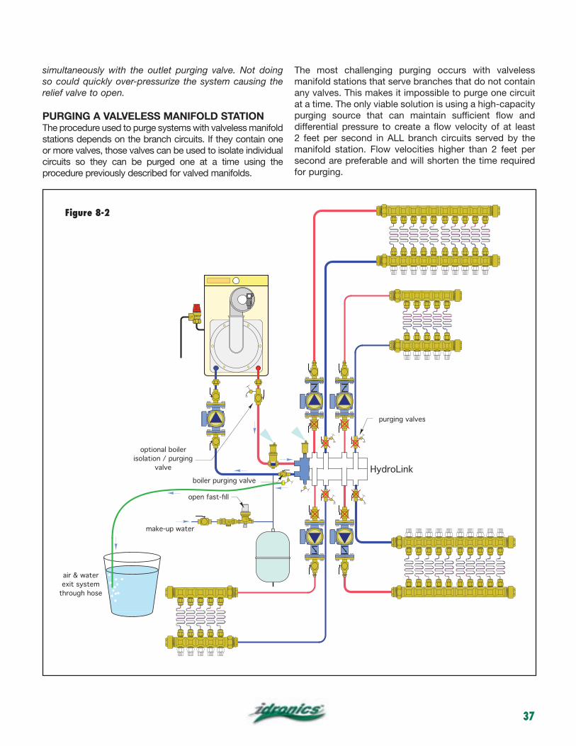
37
simultaneously with the outlet purging valve. Not doing so could quickly over-pressurize the system causing the relief valve to open.
PURGING A VALVELESS MANIFOLD STATIONThe procedure used to purge systems with valveless manifold stations depends on the branch circuits. If they contain one or more valves, those valves can be used to isolate individual circuits so they can be purged one at a time using the procedure previously described for valved manifolds.
The most challenging purging occurs with valveless manifold stations that serve branches that do not contain any valves. This makes it impossible to purge one circuit at a time. The only viable solution is using a high-capacity purging source that can maintain sufficient flow and differential pressure to create a flow velocity of at least 2 feet per second in ALL branch circuits served by the manifold station. Flow velocities higher than 2 feet per second are preferable and will shorten the time required for purging.
VENT
HydroLink
purging valves
boiler purging valve
make-up water
optional boiler
isolation / purging
valve
air & water
exit system
through hose
Figure 8-2
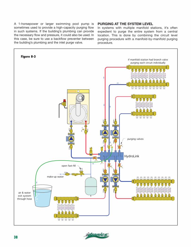
38
A 1-horsepower or larger swimming pool pump is sometimes used to provide a high-capacity purging flow in such systems. If the building’s plumbing can provide the necessary flow and pressure, it could also be used. In this case, be sure to use a backflow preventer between the building’s plumbing and the inlet purge valve.
PURGING AT THE SYSTEM LEVELIn systems with multiple manifold stations, it’s often expedient to purge the entire system from a central location. This is done by combining the circuit level purging procedure with a manifold-by-manifold purging procedure.
VENT
HydroLink
purging valves
make-up water
air & water
exit system
through hose
if manifold station had branch valve
purging each circuit individually
Figure 8-3
39
Consider the system shown in figure 8-2. It consists of a HydroLink manifold serving four zone manifold stations used for radiant panel heating. The return pipe from each manifold station is equipped with a purging valve before it connects to the HydroLink.
Purging can begin at the boiler subcircuit. Close the inline ball in the purging valve where the boiler inlet pipe enters the HydroLink. Connect the discharge hose to the hose bib on this purging valve and open the hose bib. Close the isolation flanges on the zone circulators and the purging valves on the return pipe from each zone. Enable the fast fill mode on the system’s feed valve to allow maximum flow through the make-up water assembly. Air will be pushed through the boiler and eventually out the purging hose. Continue purging until the exiting stream is free of visible air.
Next, purge one of the zone circuits served by the HydroLink as shown in figure 8-3.
Move the purging hose to the discharge connection on the zone purging valve. Close the inline ball valve within the purging valve. Be sure the circulator isolation flanges and all other valves, including all the manifold valves, are open. Next, enable the fast fill mode on the feed water valve to force flow through the zone circuit, including all the manifold circuits. Continue this mode until the stream leaving the discharge hose is free of visible water.
If the manifold being purged has individual circuit valves additional steps can be taken. Go to the manifold station and close all but one of the branch circuit shut-off valves. This forces purging flow through one branch circuit. If additional air exits the discharge hose continue purging until the stream is free of air. Open the next manifold valve and close the previous one. Repeat this procedure across the manifold station, one branch at a time, until each circuit has been individually purged. Finally, open all valves on the manifold, and close the zone purging valve.
Repeat this procedure for each manifold station in the system.
SUMMARY Although rigid metal piping has served a vital role in the development of hydronics technology, the advent of PEX and PEX-AL-PEX tubing has significantly expanded the possibilities for present and future hydronic system design. Manifold distribution systems using PEX or PEX-AL-PEX tubing provide new opportunities for creative design of hydronic heating and cooling systems.
Manifold-based distribution systems deliver the desirable operating characteristics of consistent delivery temperature to heat emitters while still allowing individual circuit level control. This makes them ideal for use with outdoor reset control, and even chilled water cooling applications.
They also provide installation flexibility that goes far beyond that available with rigid tubing. This is especially appreciated in retrofit applications.
Manifold-based distribution can be used with contemporary systems such as hydronic radiant floor heating, as well as with traditional heat emitters such as fin-tube baseboard, fan-coils and even cast-iron radiators. They are ideally suited for use with variable speed pressure-regulated circulators.
The electrical operating cost of a manifold distribution system is often lower than with other systems of comparable heat delivery capability.
Given these advantages and benefits, it’s clear that manifold-based distribution systems define the state-of-the-art in hydronics technology.
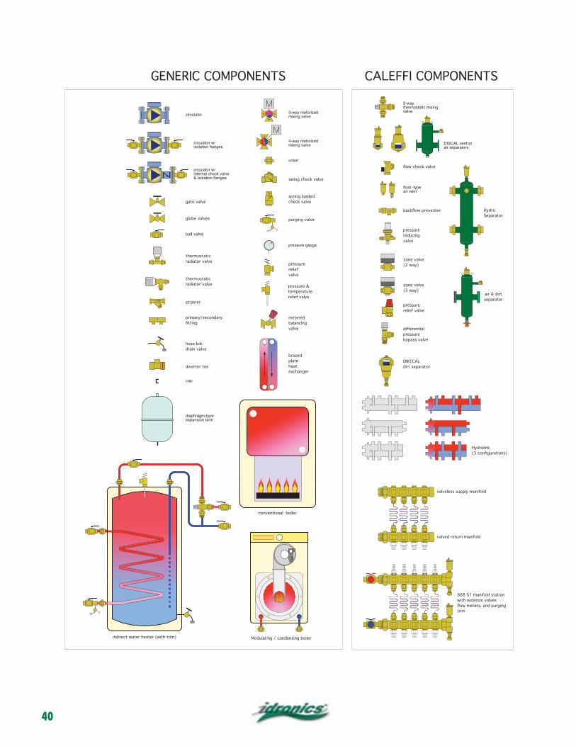
40
circulator
circulator w/
circulator w/
gate valve
globe valves
ball valve
valve
union
check valve
valve
valve
heat
VENT
GENERIC COMPONENTS CALEFFI COMPONENTS
DIRTCAL
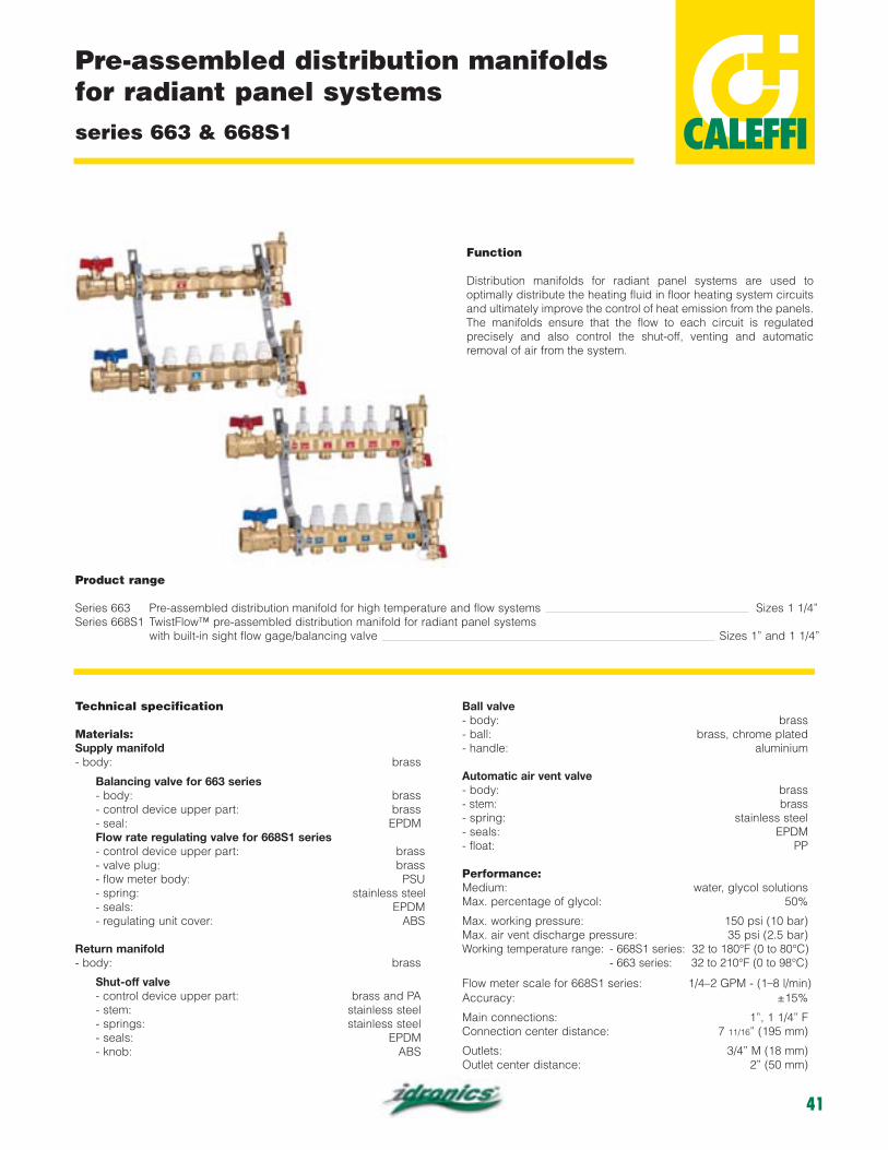
41

42
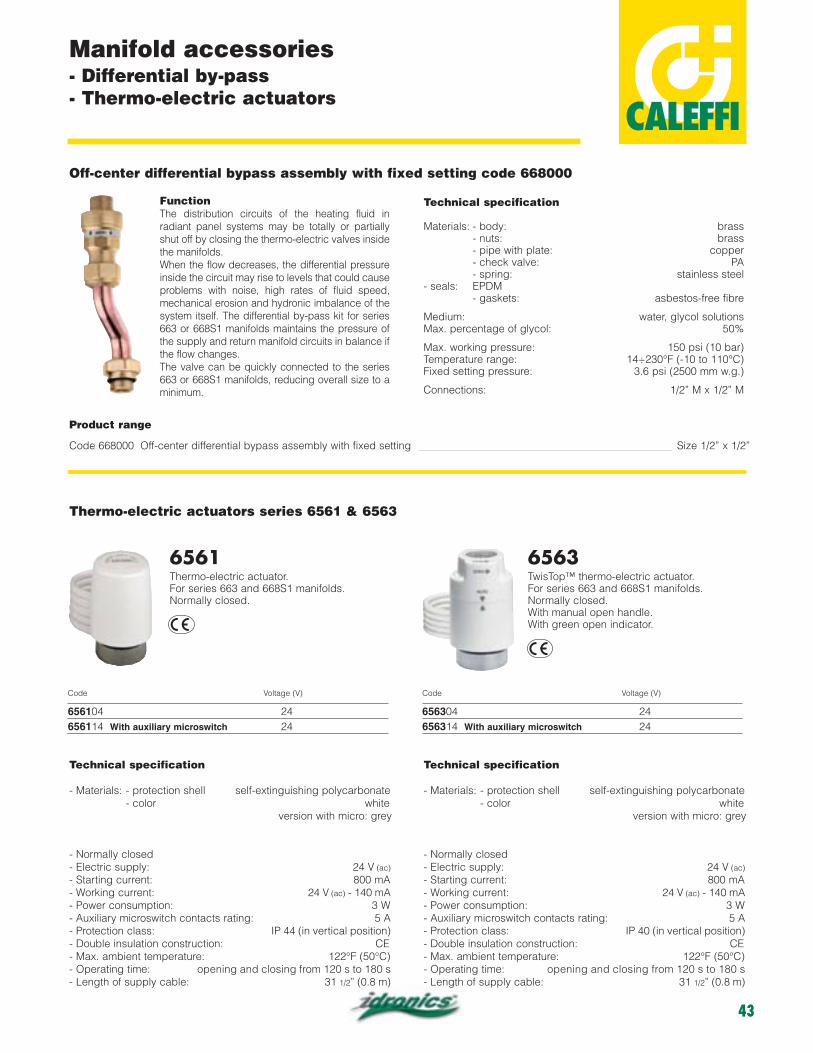
43
