2d fringe probing of liquid film dynamics of a plug...
TRANSCRIPT

14th Int Symp on Applications of Laser Techniques to Fluid Mechanics Lisbon, Portugal, 07-10 July, 2008
- 1 -
2D Fringe Probing of Liquid Film Dynamics of a Plug Bubble in a Micropipe
Haifeng Ji1 and Huihe Qiu2 1: Department of Mechanical Engineering, Hong Kong University of Science & Technology, Hong Kong SAR, China,
[email protected] 2: Department of Mechanical Engineering, Hong Kong University of Science & Technology, Hong Kong SAR, China,
[email protected] Abstract Research on bubble dynamics and heat transfer in micropipe two-phase flows is an important area in micro electronic cooling, microfluidics and non-invasive laser/ultrasound microsurgery. For example, a pulsating heat pipe (PHP) is a very effective heat transfer device which made of a relatively long and thin sealed pipe containing both phases of the working fluid. The inner diameter of the pipe must be sufficiently small so that vapor bubbles can grow to vapor plugs in the tube. The optical diagnostic technique developed by Wang and Qiu (2005) has been further extended to probe 2D interfacial film thickness in micro capillary two-phase flows. Similar to single point measurements, the spatial frequencies from the multi-scattering measured by CCD camera are used to determine the film thickness but whole fringe image is divided into N columns for determining the special frequencies. The spatial frequency of each image column can be used to calculate the interfacial film thickness of the segment of the plug bubble. By integrating all the measured film thickness along the bubble, the interfacial film surround the whole bubble can be determined. The very fine parallel fringes are projected onto the liquid/gas-bubble interface. The scattered fringe pattern can be imaged at a proper orientation angle where the spatial frequency of the fringe pattern can be measured. To determine the spatial frequency variations during the plug/slug pulsating, a highly accurate signal processing technique for continuously evaluation of signal phases utilizing a modified fast Fourier transform algorithm was used. Through geometrical optics approach, the curvature of the cross-section of a plug can be derived from the spatial frequency of the scattering pattern on the screen. Capillary tubes, with inner diameters of 1.0mm and 0.3mm, and a length of 65mm, are used. A gas plug bubble, 5mm~20mm long, is introduced and moves through the testing part of tube, which is filled with water as the working fluid. The interference fringes produced by two incident laser sheets are scattered from the interface between gas and water, and captured by high speed camera at the speed of up to 2000 frames per second. The experimental results show that the improved method can obtain the liquid film thickness profile at the different time and can be used to analyze the status of plug bubble movement in a micropipe. Introduction Recent progress in micro- and nano-technologies has yielded a rapidly emerging area in studying fluid dynamics and heat transfer in microchannels, which have promising applications in the lab-on-a-chip devices, μTAS, DNA separation and analysis, electrokinetic micro pumps, micro heat pipes, microfuel cells and micro fluidic research, etc. Many important new technologies involve multiphase flows in mini/micro channels. Examples include a high efficient gas-liquid-solid micro fluidics hydrogenation reactor (Kobayashi et al. 2004), a promising technique utilizing air-bubble method of catheter locking with anticoagulant at the catheter tip and bactericidal properties at the catheter hub for hemodialysis access (Moore and Twardowski, 2003), prevention of gas embolism damage in surgery caused by intravascular air bubbles carried in the bloodstream (Branger and Eckmann 1999, Ayyaswamy 2004), manipulating microbubbles by ultrasonic waves (Yamakoshi 2001), cooling of electronics devices using mini/micro heat pipes (Cotter, 1984, Groll et al., 1998, Kang and Huang, 2002, Berre et al. 2003 and Groll and Khandekar 2004). Research on interfacial film dynamics, heat and mass transfer, and the dynamics characteristics of plugs/slugs in mini/microchannels are important in understanding and optimizing aforementioned processes and applications. The physical behavior of multiphase flows in mini/microchannels is

14th Int Symp on Applications of Laser Techniques to Fluid Mechanics Lisbon, Portugal, 07-10 July, 2008
- 2 -
complex because it involves interfacial transport phenomena coupled with the dynamics of thin liquid, the disjoining pressure of the phases, stability and phase change at such an interface in microscale fluids (Kobayashi et al. 2004, Moore and Twardowski, 2003, Branger and Eckmann 1999, Ayyaswamy 2004). In the direct methanol fuel cells (DMFC), the behavior of generated CO2 plugs have significant impact on the mass transfer coefficient of the fuel, which limits the performance of DMFC. A particularly interesting phenomenon associated with multiphase flows in mini/microchannels is, therefore, the interfacial film dynamics caused by the liquid surface tension, the surface energy of the wall, the flow and plug/slug velocities, the gas property and the geometry of the groove structures. Progress in understanding the interfacial film dynamics, heat and mass transfer and fluid flows of plug/slug bubbles in a mini/microchannel has relied on experimental investigation due to the complexity of the process. Since the interfacial film thickness between a plug/slug bubble in a mini/microfluidic device has length scales of 1-100μm, traditional flow diagnostic tools cannot be used. Most measurements in two-phase microfluidic devices have been limited to the qualitative visualization techniques or bulk property measurements of two-phase flows. Recently, advances in micro-resolution particle image velocimetry (PIV) have become available for microflow field measurements (Meihart et al. 1999, Tian and Qiu 2002). Many techniques have been developed to measure the liquid film thickness, such as optical method (Xishi Wang, Huihe Qiu, 2005; Wali M. Nozhat, 1997; S. C. M. Yu, C. P. Tso and R. Liew, 1996), microwave method (R.P. Roy, J. Ku, B.Kaufman, J. Shukla, 1986), ultrasonic method (T. Kamei, A. Serizawa, 1998), electrical impedance method (Tohru Fukano, 1998), conductimetry method (Patrice Tisné, Louis Doubliez, Fethi Aloui, 2004) and capacitance method (Mustafa R. Özgü, John C. Chen, Nikolai Eberhardt, 1973; Billy W. Marshall, William G. Tiederman, 1972). However, these methods obtain the local film thickness information and can not measure the whole film thickness profile at the same time. In this paper, based on the previous research results, the extended measurement method of the whole film thickness profile is presented. The approach is based on the spatial fringe scattering method, where the spatial frequency of scattered fringes is a function of liquid film thickness. In the improved method, the laser sheet is used instead of the laser beam, and the width of laser sheet can cover the whole bubble, which can implement the profile measurement of liquid film thickness. Methodology Based on the method proposed by Wang and Qiu [1], the film thickness measurement method is further extended. Figure 1 shows the schematic of a moving bubble in a capillary pipe where the advancing and receding contact angles are different at the front and the end of the bubble. When two incident laser sheets form a cross-sectional area along the tube, parallel interference fringes will be formed in the intersection area. The fringes are focused onto the bubble surface and scattered from the interface between gas and liquid. Capturing the image of the scattered fringes by using a high speed CCD camera, the spatial frequencies of the received fringe image along the tube can be measured. Due to the change of the curvature of the interface between gas and liquid with the film thickness, the reflecting fringes will shift and extend. The motion of the bubble can make the spatial frequency of the fringes change. According to Wang and Qiu (2005) the measured spatial frequency is a function of the film thickness at that location being measured [1].

14th Int Symp on Applications of Laser Techniques to Fluid Mechanics Lisbon, Portugal, 07-10 July, 2008
- 3 -
Water
Bubble
Micropipe
Film Thickness(H)
Moving Direction
Figure 1 Ideal Bubble in the micropipe
As shown in Figure 2, the relation between 2D film thickness h(z) and the spatial frequency of the scattering fringes can be described by equation (1):
( ) ( )
( )( )( ) ( ) ( )
2
220
22
cos1
sin11
cos1
1sin
⎥⎥⎦
⎤
⎢⎢⎣
⎡−
−+
+−=
zczczfzf
zc
zcRRzh
θθθ
θ (1)
where f0(z) is the spatial frequency of the fringes along the z direction when the capillary tube is empty which reflected by the glass/air interface, ( )zf is the spatial frequency of scattering fringes along the z direction when a bubble slug go through the tube, c=ng/nl, R is the radius of capillary tube, and θ(z) is the incident angle on the glass/liquid interface at location z, which can be determined below:
( ) ( ) ( ) ( )( )( )( )
( )( ) ⎟
⎟
⎠
⎞
⎜⎜
⎝
⎛
−−−
=−−zc
zczhRRzhRzhzz
θθθβθβ
22
2
sin1sin
22sin
2cossin1
2sin (2)
where, β is the orientation angle of the receiving optics (CCD camera) and gn , ln is the refractive index of the glass and the liquid respectively.
Figure 2 Schematic of the geometrical optical approach for scattering rays from a gas plug

14th Int Symp on Applications of Laser Techniques to Fluid Mechanics Lisbon, Portugal, 07-10 July, 2008
- 4 -
In equation (1), R and c is known; 0f (z) and f (z) can be calculated by the fringes received from high speed CCD camera; the incident angle θ (z) can be calculated by the iterative method (Wang and Qiu (2005)). The film thickness can then be obtained through the equation (1). In this paper, four conditions are considered first as indicated in Figure 3 where optical beam that is reflected by the interface between liquid and inner wall of capillary tube (B-1); optical beam that is refracted in the liquid, but does not reach the interface between liquid and gas (B-2); optical beam that is refracted in the liquid, and that is reflected by the interface between liquid and gas (B-3); optical beam that is refracted in the liquid, and that is refracted in gas (B-4).
Gas
Water
Incident Beam
Exit Beam
B-1 B-2
B-3 B-4
Figure 3 Four Types of Optical Beam with Reflection and Refraction
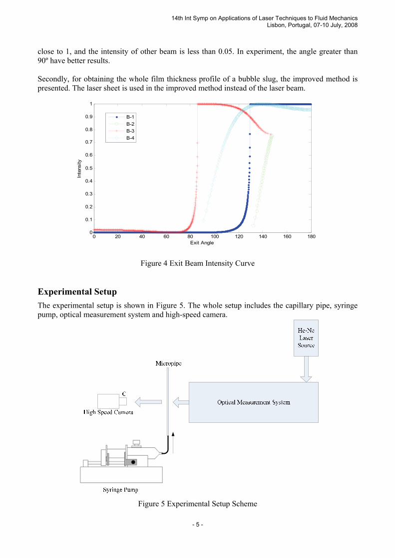
The intensity of scattering laser is also analyzed. One of simulation results is shown in Figure 4. Other results are similar with Figure 4. Assume that the intensity of incident beam is 1, that the inner diameter of capillary tube is 1mm, and that the simulated film thickness is 10μm. Here, only the reflecting beam and first order refracting beam are considered, and the absorption of material is ignored. In Figure 4, the x-axis is exit angle and y-axis is intensity. The exit angle presents the angle at which we will receive the scattering beam through high speed camera. From Figure 4, we can see the difference of scattering beam intensity among the four cases. In our experiment, the sufficiently received laser intensity and less noise from other scattering beam are the basic requests. Then, the received angle range from 87º to 93º is selected. In this range, the intensity of B-3 scattering beam
14th Int Symp on Applications of Laser Techniques to Fluid Mechanics Lisbon, Portugal, 07-10 July, 2008
- 5 -
close to 1, and the intensity of other beam is less than 0.05. In experiment, the angle greater than 90º have better results. Secondly, for obtaining the whole film thickness profile of a bubble slug, the improved method is presented. The laser sheet is used in the improved method instead of the laser beam.
0 20 40 60 80 100 120 140 160 1800
0.1
0.2
0.3
0.4
0.5
0.6
0.7
0.8
0.9
1
Exit Angle
Inte
nsity
B-1B-2B-3B-4
Figure 4 Exit Beam Intensity Curve Experimental Setup The experimental setup is shown in Figure 5. The whole setup includes the capillary pipe, syringe pump, optical measurement system and high-speed camera.
Figure 5 Experimental Setup Scheme
14th Int Symp on Applications of Laser Techniques to Fluid Mechanics Lisbon, Portugal, 07-10 July, 2008
- 6 -
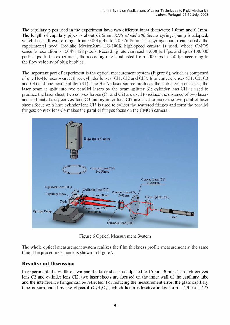
The capillary pipes used in the experiment have two different inner diameters: 1.0mm and 0.3mm. The length of capillary pipes is about 62.5mm. KDS Model 200 Series syringe pump is adopted, which has a flowrate range from 0.001μl/hr to 70.57ml/min. The syringe pump can satisfy the experimental need. Redlake MotionXtra HG-100K high-speed camera is used, whose CMOS sensor’s resolution is 1504×1128 pixels. Recording rate can reach 1,000 full fps, and up to 100,000 partial fps. In the experiment, the recording rate is adjusted from 2000 fps to 250 fps according to the flow velocity of plug bubbles. The important part of experiment is the optical measurement system (Figure 6), which is composed of one He-Ne laser source, three cylinder lenses (Cl1, Cl2 and Cl3), four convex lenses (C1, C2, C3 and C4) and one beam splitter (S1). The He-Ne laser source produces the stable coherent laser; the laser beam is split into two parallel lasers by the beam splitter S1; cylinder lens Cl1 is used to produce the laser sheet; two convex lenses (C1 and C2) are used to reduce the distance of two lasers and collimate laser; convex lens C3 and cylinder lens Cl2 are used to make the two parallel laser sheets focus on a line; cylinder lens Cl3 is used to collect the scattered fringes and form the parallel fringes; convex lens C4 makes the parallel fringes focus on the CMOS camera.
Figure 6 Optical Measurement System
The whole optical measurement system realizes the film thickness profile measurement at the same time. The procedure scheme is shown in Figure 7. Results and Discussion In experiment, the width of two parallel laser sheets is adjusted to 15mm~30mm. Through convex lens C2 and cylinder lens Cl2, two laser sheets are focused on the inner wall of the capillary tube and the interference fringes can be reflected. For reducing the measurement error, the glass capillary tube is surrounded by the glycerol (C3H8O3), which has a refractive index form 1.470 to 1.475

14th Int Symp on Applications of Laser Techniques to Fluid Mechanics Lisbon, Portugal, 07-10 July, 2008
- 7 -
(20ºC, 589 nm), similar to the refractive index of glass (1.473). By using this refractive index matching method, the influence of glass tube can, therefore, be negligible.
Adjust optical path, obtain good fringes from camera; record the interference fringe image of empty tube
Fill water in the measurement tube, and inject air bubble; set the flowrate of syringe pump, and start it.
When the flow is stable and the plug bubble goes through testing tube, record the corresponding image.
According to the fringe image, calculate f0 and f series through FFT using five-point fitting method
Calculate the film thickness using equation (1), and obtain the thickness profile.
Figure 7 Procedure of Calculating Liquid Film Thickness
The capillary tube with 1.0mm inner diameter and 1.5mm outer diameter is used. The length of gas plug bubble is from 5mm to 15mm. The velocity of bubble plug is from 0.002m/s to 1.167m/s. As an example, the fringe image captured by high speed camera is shown in Figure 8. Figure 8(a) is the fringe image of empty tube; Figure 8(b) is the fringe image of bubble plug with the velocity of 0.098m/s; Figure 8(c) is the fringe image of bubble plug with the velocity of 0.361m/s; Figure 8(d) is the fringe image of bubble plug with the velocity of 0.509m/s. In Figure 8, the fringe distributions at different velocities have obvious shift and variation comparing that of empty tube. At low velocity, we can clearly identify the air plug bubble from the image but at high velocity, the liquid film fluctuation becomes larger, then the scattering fringes become complex. In Figure 8(c) and 8(d), the longitudinal light and shade variation come out because the film waves produced by the fluctuation makes the laser ray changed. At the liquid wave crest, the fringes become dark and at the liquid wave valley, the fringes become light.

14th Int Symp on Applications of Laser Techniques to Fluid Mechanics Lisbon, Portugal, 07-10 July, 2008
- 8 -
For reducing the noise influence, every 50 pixels are used to calculate one film thickness of bubble plug at the x-axis direction. Figure 9 shows some results of the whole film thickness profile at different velocity and different plug bubble length.
(a) (b) (c) (d)
Figure 8 Interference fringe image at different flowrate
(capillary tube with 1.0mm inner diameter)
From Figure 9, we can see the whole plug bubble in capillary tube. The front-end of bubble varies slowly (for example, in Figure 9(a), the liquid film thickness from 3μm slowly down to 1μm, about 0.2mm long), and the back-end of bubble varies quickly (the liquid film thickness from 2μm quickly up to 10μm, nearly no length). The fluctuation of liquid film exists, and the larger velocity is, the stronger the fluctuation becomes.
The mean film thickness at different velocity is analyzed (in Figure 10, capillary number σμVCa = ,
where μ is viscosity, V is velocity and σ is liquid surface tension). The figure shows that the average film thickness becomes large with the velocity of plug bubble, but the variation is not linear. At low velocity, the film thickness has obvious change with the increase of plug bubble velocity. When the velocity reaches some value, the film thickness (here, about after 1m/s) changes very slowly. In the experiment, the capillary tube with 0.3mm inner diameter and 1.0mm outer diameter is adopted. However, since the curvature of the interface of gas and liquid becomes large, the number of fringe captured by camera decreases. In this experiment, only about 5 fringes are obtained, moreover, the image is not very good and there are some big noises in it. Conclusion Based on the spatial fringe scattering method, an improved film thickness measurement method is used to obtain the liquid film thickness profile of the whole plug bubble in capillary tube simultaneously. In this method, the laser sheet is used instead of the laser beam, and the width of laser sheet can cover the whole bubble. So the method can implement the profile measurement of liquid film thickness. The experimental results show that the improved method is effective. According to the liquid film thickness profile, it is validated that there is fluctuation when the plug bubble moves in the capillary tube, and the larger velocity of plug bubble is, the stronger the fluctuation becomes. The average film thickness at different velocity is analyzed. The results show that the film thickness becomes great with the increasing velocity, and when the velocity reaches some value, the film thickness variation will become small.

14th Int Symp on Applications of Laser Techniques to Fluid Mechanics Lisbon, Portugal, 07-10 July, 2008
- 9 -
1 2 3 4 5 6
x 10-3
0
5
10
0.5 1 1.5 2 2.5 3
x 10-3
0
5
10
Film
Thi
ckne
ss (μ
m)
Length of Plug Bubble (m)
Front-end Back-end
(a) 3.5mm-long Plug Bubble profile at the velocity of 0.098m/s
Film
Thi
ckne
ss (μ
m)
Length of Plug Bubble (m) (b) 6.0mm-long Plug Bubble profile at the velocity of 0.361m/s
Back-end Front-end
0.5 1 1.5 2 2.5 3
x 10-3
10
20
30
40
Film
Thi
ckne
ss (μ
m)
Length of Plug Bubble (m)
(c) 3.0 mm-long Plug Bubble profile at the velocity of 0.509m/s
Front-end Back-end
Figure 9 Plug bubble film thickness profile
Acknowledgement This research was supported by the Hong Kong Government under RGC (Research Grants Council) grant No HKUST 6230/02E and 6194/03E.

14th Int Symp on Applications of Laser Techniques to Fluid Mechanics Lisbon, Portugal, 07-10 July, 2008
- 10 -
Capillary Number Ca
Ave
rage
Film
Thi
ckne
ss (μ
m)
0 0.002 0.004 0.006 0.008 0.01 0.012 0.014 0.016 0.0180
5
10
15
20
Figure 10 Average film thickness vs. velocity
Reference: 1. Xishi Wang and Huihe Qiu, Fringe probing of liquid film thickness of a plug bubble in a
micropipe, Meas. Sci. Technol, 2005, 16: 594-600. 2. Wali M. Nozhat, Measurement of liquid-film thickness by laser interferometry, APPLIED
OPTICS, 1997, 36(30): 7864-7869. 3. S. C. M. Yu, C. P. Tso and R. Liew, Analysis of thin film thickness determination in two-phase
flow using a multifiber optical sensor, Appl. Math. Modelling, 1996, 20: 540-548. 4. R.P. Roy, J. Ku, B.Kaufman, J. Shukla, Microwave method for measurement of liquid film
thickness in gas-liquid flow, Rev. Sci. Instrum, 1986, 57(5):952-956. 5. T. Kamei, A. Serizawa, Measurement of 2-dimensional local instantaneous liquid film thickness
around simulated nuclear fuel rod by ultrasonic transmission technique, Nuclear Engineering and Design, 1998, 184: 349–362.
6. Tohru Fukano, Measurement of time varying thickness of liquid film flowing with high speed gas flow by a constant electric current method (CECM)Nuclear Engineering and Design, 1998, 184: 363–377.
7. Patrice Tisné, Louis Doubliez, Fethi Aloui, Determination of the slip layer thickness for a wet foam flow, Colloids and Surfaces A: Physicochem. Eng. Aspects, 2004, 246: 21–29.
8. Mustafa R. Özgü, John C. Chen, Nikolai Eberhardt, A capacitance method for measurement of film thickness in two-phase flow, Rev. Sci. Instrum, 1973, 44(12): 1714-1716.
9. Billy W. Marshall, William G. Tiederman, A Capacitance Depth Gauge for Thin Liquid Films, Rev. Sci. Instrum., 1972,43(3): 544–547.
10. H. H. Qiu, and C. T. Hsu, Minimum deviation of spatial frequency in large particle sizing, Appl. Opt. 1998, 37: 6787–6794.
11. H. H. Qiu and C. T. Hsu, The impact of high order refraction on optical microbubble sizing in multiphase flows, Exp. Fluids, 2004, 36: 100–107.
12. H. H. Qiu, M. Sommerfeld and F. Durst, High-resolution data processing for phase-Doppler measurements in a complex two-phase flow, Meas. Sci. Technol., 1991, 2: 455–63.