2nd corrigendum to tender call notice no: 69/ 2011-12.old.optcl.co.in/ten/htls_rkp.pdf · ·...
TRANSCRIPT
1
2nd Corrigendum to tender call notice No: 69/ 2011-12. For and on behalf of ODISHA POWER TRANSMISSION CORPORATION LIMITED, the last date of receipt & opening of tender notice No: 69/2011-12 & Tender specification No.78/2011-12 is extended to date 05/06/2012 up to 1P.M & to be opened on date 05/06/2012 at 3.30 P.M. The interested manufacturers/authorized supplier of HTLS conductor may visit our web site http://www.optcl.co.in, for detail amendments to the specification. Senior General Manager (CPC)
Clarifications to the Pre bid conference. 1) 6.1 m ground clearance is required by OPTCL at 800A continuous flow at span length of 320 m. The tension & sag at different conditions are specified at clause No. 2.2.3 (sag tension requirement) of technical specification 2) Line profiles are available with OPTCL .The bidders can collect the approved hard copies of the profile from the office of the Sr. GM (CPC). 3) The circuit kilometer of the lines where ACSR conductor will be replaced is 99.70 KM. Chandaka- Mancheswar line is drawn over single circuit towers & double circuit towers. Hot line stringing will be required where double circuit towers are used, as detailed in the tower schedule. 4) Training will be imparted to four batches of three days duration to each batch. 5) Wind Speed at stand still-0.6 m/sec. 9) Mid-span joints will be allowed if section length between tension towers is more than 1500 meters. 6) High temperature endurance & creep test –Being the generic test, previous test reports of similar size or higher size of same technology product shall be accepted. 7) Annexure –10, is not required, as no JV agreement is required by OPTCL. 8) Authorized Indian manufacturer must have manufacturing facility of aluminum conductor, aluminum alloy conductor, & must have manufactured these conductors of quantity not less than 35% of the tendered quantity within last five years from the date of opening of the bid. Or 50% of the tendered quantity as indicated in the package in two orders. Or 60% of the tendered quantity as indicated in the package in three orders 9) Thermal stability test of core for continuous operating temperature of 180 deg is to be submitted.
2
10) In the event OPTCL receives only one technically approved bid, OPTCL will consider it. 11) In the price schedule for erection portion Sl.No. 3 “Dismantling of existing ACSR Panther Conductor with hardware fittings in 132kV Chandaka-Ranasinghpur Line & handing over the same at OPTCL store” quantity may please be read as 24.25 KM instead of 57.25 KM. AMMENDED CLAUSES Clause-2. Of Instruction to Bidders ( ITB).MINIMUM QUALIFYING REQUIREMENTS OF BIDDERS 2.1 This bidding is open to any Indian manufacturer of aluminium or aluminium alloy
conductor with or without having facility to manufacture HTLS conductor. In case
manufacturer not having facility to manufacture HTLS conductor, they can have
authorization from principal manufacturer to import & supply the HTLS conductor. In
case Indian manufacturer is having the HTLS manufacturing facility, he is having the
option either to import the entire conductor or to import core from the principal
manufacturer of HTLS conductor & manufacture the conductor at his factory and supply
the same. In all such cases the experience of principal manufacturer as per clause No.
2.1.1, 2.1.2, 2.1.3 & 2.1.4 shall be taken in to consideration.
The authorization of the principal manufacturer should be valid as on the date of
opening of the techno commercial bid & is to be extended up to the completion of the
project.
In case of Indian manufacturer imports the conductor / core, the following documents to be furnished before inspection of materials in India.
(i) Invoice of the supplier. (ii) Mill’s test certificates. (iii) Packing list. (iv) Bill of lading.
(v) Bill of entry certificates by customs.
2.1.1 The bidder or his principal manufacturer of HTLS conductor should have supplied not
less than 35% of the tendered quantity as indicated in the respective packages in a single
order. or
50% of the tendered quantity as indicated in the package in two orders.
or
3
60% of the tendered quantity as indicated in the package in three orders
2.1.2 The above supply should have been completed during last five years from the date of
opening of the tender.
2.1.3 The above supplied material should be in successful operation for a minimum period
of one year, as on the date of submission of bid. The performance certificate of user
utilities should be furnished along with the bid.
2.1.4 Type tests carried out on the proposed conductor or on higher size conductor of the
same technology within last five years are to be submitted with the bid, in line with the
relevant National / International standards (Copy of the standards to be submitted with the
bid). In case the bidder is a authorized manufacturer of the principal manufacturer, the type
test of the similar conductor being manufactured by the principal manufacturer will also be
considered valid
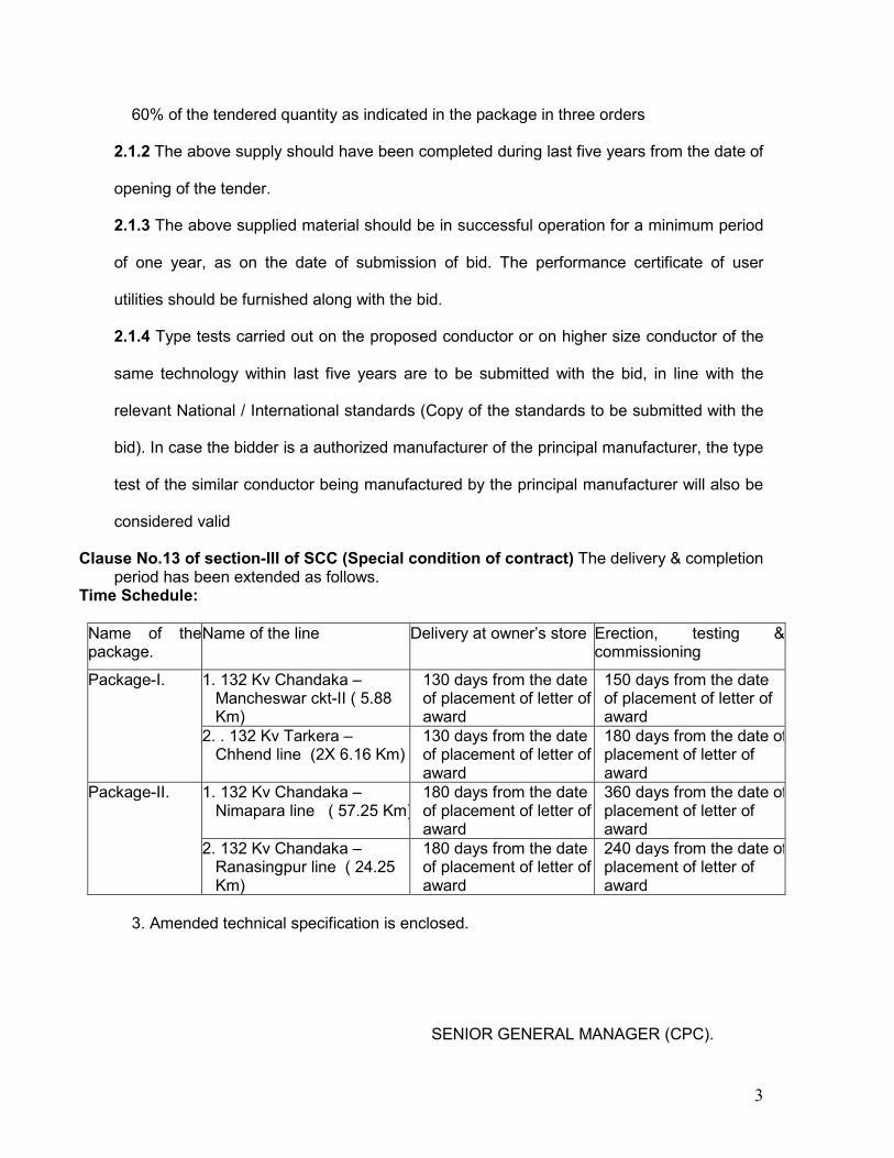
Clause No.13 of section-III of SCC (Special condition of contract) The delivery & completion period has been extended as follows.
Time Schedule:
Name of the package.
Name of the line Delivery at owner’s store Erection, testing & commissioning
Package-I. 1. 132 Kv Chandaka – Mancheswar ckt-II ( 5.88 Km)
130 days from the date of placement of letter of award
150 days from the date of placement of letter of award
2. . 132 Kv Tarkera – Chhend line (2X 6.16 Km)
130 days from the date of placement of letter of award
180 days from the date of placement of letter of award
Package-II. 1. 132 Kv Chandaka – Nimapara line ( 57.25 Km)
180 days from the date of placement of letter of award
360 days from the date of placement of letter of award
2. 132 Kv Chandaka – Ranasingpur line ( 24.25 Km)
180 days from the date of placement of letter of award
240 days from the date of placement of letter of award
3. Amended technical specification is enclosed. SENIOR GENERAL MANAGER (CPC).
4
SECTION-V
AMMENDED
TECHNICAL SPECIFICATION
FOR REPLACEMENT OF
ACSR PANTHER CONDUCTOR BY
HTLS CONDUCTOR (Except GAP conductor).
1 .132 KV CHANDAKA-MANCHESWAR CKT-II.
2 .132 KV CHANDAKA-RANASINGPUR LINE.
3 .132 KV CHANDAKA NIMAPARA LINE.
4 132 KV TARKERA CHHEND LINE.
5
INDEX
1. GENERAL INFORMATION AND SCOPE
2. DESIGN PARAMETERS
3. STANDARDS
4. STRANDING
5. PACKING AND MARKING
6. TESTS AND STANDARDS
7. GUARANTEED TECHNICAL PARTICULARS
8. SAG TENSION CHARTS AND SAG TEMPLATES
9. ACCESSORIES
10. EXECUTION OF WORK
11. STRINGING
12. FIELD QUALITY PLAN
13. WASTAGE
14. LOSSES
15. COMMISSIONING
16. DRAWINGS AND SPECIFICATIONS
6
1.GENERAL INFORMATION AND SCOPE
1.1 Scope
1.1.1 The turnkey work involves replacement of ACSR conductor in 132KV Chandaka-Mancheswar circuit-II (route length 5.88Km) ,132KV Chandaka-Ranasingpur line (route length 24.25Km), 132kV Chandaka-Nimapara Line ( route length 57.25 Km) & 132kV Tarkera-Chhend D/C Line (route length 6.16 Km) by HTLS conductors except GAP conductor with current carrying capacity of minimum 800A. This includes replacement of conductor of the transmission lines from gantry to gantry, at both ends of the lines.
The work involves dismantling of existing ACSR Panther Conductor, supply of HTLS conductor of minimum 800 A capacity corresponding to 180ºC & with unit weight equal to or less than that of ACSR Panther conductor and associated conductor hard ware fittings, clamps & vibration dampers and stringing of the HTLS conductor on existing 132KV transmission line structure and disc insulators after survey of the lines & delivery of the dismantled materials at the nearest stores of the owner, training to OPTCL employees & other personnel as identified by the owner, on stringing of HTLS conductors. . ROW, if any for execution of work & approach to work site shall be resolved by the contractor at his cost. However, OPTCL will provide necessary assistance. Shut down will be allowed form 5 AM to 5 PM on daily basis for the replacement work. The contractor has to do the stringing within this interval so that line can be charged at 5 PM every day. However the guaranteed shut down period for each day is eight hours.
1.1.2 Submission of complete technical details of the proposed HTLS conductor with relevant calculation along with the bid to adjudge the sufficiency of existing towers for carrying out the up-rating works. This shall be carried out in compliances / adherence to all safety and standard requirements as per Indian Electricity Rules 1956. Design parameters and submission of detailed drawings of conductor hardware and accessories and preparation of sag tension chart, stringing chart, of the conductor used showing, sag & tension at various temperatures are included in the scope of the Bidder.
1.1.3 The existing insulators shall be inspected by the contractor in advance for any defects and those found defective shall be replaced with good ones by OPTCL. During stringing if any existing insulator found defective, it will be supplied by OPTCL.
1.1.4 The entire stringing work of HTLS conductor shall be carried out by tension stringing machine except where geographical / topographical or other site constraints do not permit use of tension stringing equipment. In such cases manual stringing along with other appropriate tools and equipment may be employed with the approval of engineer in charge. The bidder shall indicate in the offer, the sets of tension stringing equipment he is having in his possession and the sets of stringing equipment he would deploy exclusively for this package. The contractor shall also engage sufficient
7
manpower so that stringing of the conductor in one stretch is complete within the allowed shut down period of one day. No mid span joint will be allowed & hence the length of the conductor shall be decided by referring the tower schedule.
1.1.5 In 132KV Chandaka-Mancheswar circuit-II, all locations will be provided with double insulator strings at both suspension and tension points. In case of other lines, only road & river crossings and lines passing over civil structures will have double insulator strings. Vibration dampers are to be provided in all suspension & tension locations.
1.1.6 The rollers, which will be used during stringing, should be so designed that the line can be charged with the roller.
1.1.7 One conductor-manufacturing engineer should remain present on the site during erection process.
1.1.8 Award has been placed for under ground cable from gantry of Chandaka Grid Sub station to location No.3 of Chandaka –Mancheswar Ckt-II (Length-0.352 Km), gantry of Chandaka Grid Sub station to location No.4 of Chandaka –Nimapara line ( length-0.305 Km) & gantry of Chandaka Grid Sub station to location No.4 of Chandaka –Ransinghpur line ( length-0.305 Km) . If the cabling work is complete before manufacture of HTLS conductor, the conductor, & accessories quantity will be reduced accordingly. But the offer to be made for the entire route length for evaluation purpose.
1.1.9 The project scope is split in to two packages. I) Package-I, 132 KV Chandaka- Mancheswar & Tarkera- Chhend (D/C Line).
II) Package-II, 132 Kv Chandaka- Nimapara & Chandaka- Ransingpur. Intending bidders can either participate in package-I, or in package-II, or in both package-I & II. EMD for package-I =Rs 36.4 Lakhs. EMD for package-II=Rs 1.63 Crore. EMD for package-I & II (Combining)=Rs 1.994 Crore. In the event of an eligible bidder becoming L1 in both the packages, they will be considered for award of both the packages provided they meet the combined eligibility criteria as per clause 2.1, 2.1.1 to 2.1.4 of section-I (ITB). Otherwise they will be awarded only one package out of the two at the discretion of OPTCL considering the least cost to OPTCL. 2. DESIGN PARAMETERS
2.1 Technical Particulars of HTLS Conductor
The design and other parameters on which the up rating is to be planned are:
The HTLS conductor shall meet the following minimum requirements:
Overall diameter of complete conductor Not exceeding 21mm ± 5%
Approx. mass of complete Less than or equal to 974 kg/km
8
conductor (kg/Km)
Direction of lay of outer layer Right Hand
The bidder shall indicate the technical particulars and details of the construction of the conductor in the relevant schedule of GTP. The bidder shall also guarantee the DC resistance of conductor at 20 deg C and AC resistance at the calculated temperature corresponding to 50Hz alternating current flow of 800 amperes per conductor at specified ambient conditions (maximum continuous operating temperature).
The bidder shall submit the supporting calculations for the AC resistance indicating details & justifications of values of temperature coefficient of resistance & DC to AC resistance conversion factor(s) with due reference to construction / geometry of the conductor.
2.2 Climatic & Technical details: The climatic and system parameters are detailed
below.
2.2.1 Climate details.
Location:- In the state of Orissa
Maximum ambient temperature= 50 ºC
Minimum ambient temperature=05 ºC
Every day temperature=32ºC
Maximum relative humidity=100%
Average rainfall per year=1150mm. Approx.
Isokeraunic level = 100 / year
Number of rainy days per year = 100 days
Altitude = Less than 350 Meters.
2.2.2 Current Carrying Capacity / Ampacity Requirements
Each HTLS conductor shall be suitable to carry minimum 50 Hz alternating current of 800 Amperes conductor under the ambient conditions & maximum conductor sag specified below while satisfying other specified technical requirements/ parameters.
Ambient temperature: 50 deg C
Solar Absorption coefficient =0.8
Solar Radiation = 1045 watt/sq.m
Emisitivity Constant= 0.45
Wind velocity = 0.6 m/sec
9
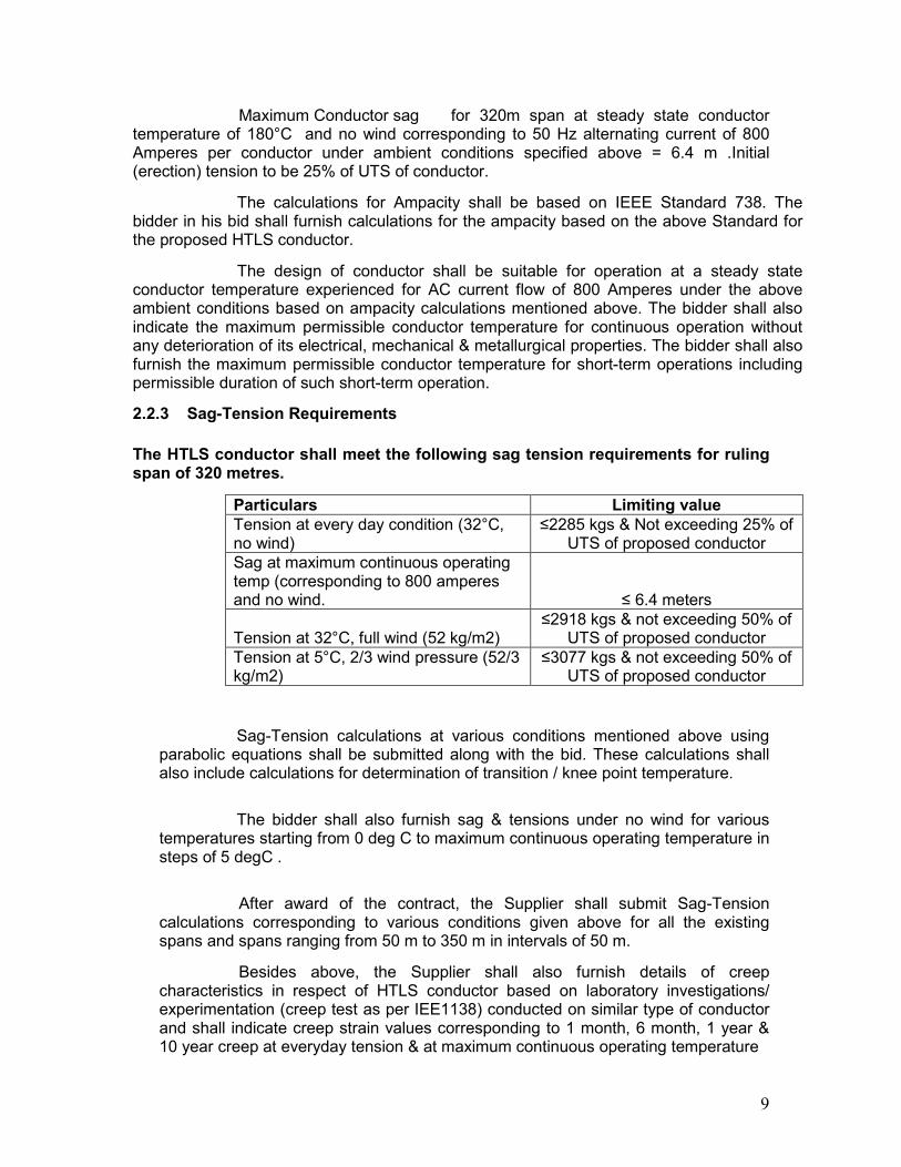
Maximum Conductor sag for 320m span at steady state conductor temperature of 180°C and no wind corresponding to 50 Hz alternating current of 800 Amperes per conductor under ambient conditions specified above = 6.4 m .Initial (erection) tension to be 25% of UTS of conductor.
The calculations for Ampacity shall be based on IEEE Standard 738. The bidder in his bid shall furnish calculations for the ampacity based on the above Standard for the proposed HTLS conductor.
The design of conductor shall be suitable for operation at a steady state conductor temperature experienced for AC current flow of 800 Amperes under the above ambient conditions based on ampacity calculations mentioned above. The bidder shall also indicate the maximum permissible conductor temperature for continuous operation without any deterioration of its electrical, mechanical & metallurgical properties. The bidder shall also furnish the maximum permissible conductor temperature for short-term operations including permissible duration of such short-term operation.
2.2.3 Sag-Tension Requirements
The HTLS conductor shall meet the following sag tension requirements for ruling span of 320 metres.
Particulars Limiting value Tension at every day condition (32°C, no wind)
≤2285 kgs & Not exceeding 25% of UTS of proposed conductor
Sag at maximum continuous operating temp (corresponding to 800 amperes and no wind. ≤ 6.4 meters
Tension at 32°C, full wind (52 kg/m2) ≤2918 kgs & not exceeding 50% of
UTS of proposed conductor Tension at 5°C, 2/3 wind pressure (52/3 kg/m2)
≤3077 kgs & not exceeding 50% of UTS of proposed conductor
Sag-Tension calculations at various conditions mentioned above using parabolic equations shall be submitted along with the bid. These calculations shall also include calculations for determination of transition / knee point temperature.
The bidder shall also furnish sag & tensions under no wind for various temperatures starting from 0 deg C to maximum continuous operating temperature in steps of 5 degC .
After award of the contract, the Supplier shall submit Sag-Tension calculations corresponding to various conditions given above for all the existing spans and spans ranging from 50 m to 350 m in intervals of 50 m.
Besides above, the Supplier shall also furnish details of creep characteristics in respect of HTLS conductor based on laboratory investigations/ experimentation (creep test as per IEE1138) conducted on similar type of conductor and shall indicate creep strain values corresponding to 1 month, 6 month, 1 year & 10 year creep at everyday tension & at maximum continuous operating temperature
10
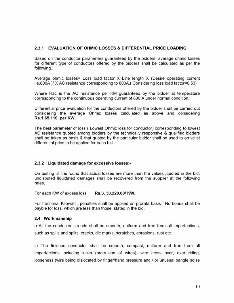
2.3.1 EVALUATION OF OHMIC LOSSES & DIFFERENTIAL PRICE LOADING.
Based on the conductor parameters guaranteed by the bidders, average ohmic losses for different type of conductors offered by the bidders shall be calculated as per the following.
Average ohmic losses= Loss load factor X Line length X (Desire operating current i.e.800A )² X AC resistance corresponding to 800A.( Considering loss load factor=0.53)
Where Rac is the AC resistance per KM guaranteed by the bidder at temperature corresponding to the continuous operating current of 800 A under normal condition.
Differential price evaluation for the conductors offered by the bidder shall be carried out considering the average Ohmic losses calculated as above and considering Rs.1,65,110. per KW.
The best parameter of loss ( Lowest Ohmic loss for conductor) corresponding to lowest AC resistance quoted among bidders by the technically responsive & qualified bidders shall be taken as basis & that quoted by the particular bidder shall be used to arrive at differential price to be applied for each bid.
2.3.2 :Liquidated damage for excessive losses:-
On testing ,if it is found that actual losses are more than the values ,quoted in the bid, undisputed liquidated damages shall be recovered from the supplier at the following rates.
For each KW of excess loss Rs.3, 30,220.00/ KW.
For fractional Kilowatt , penalties shall be applied on prorata basis . No bonus shall be payble for loss, which are less than those, stated in the bid.
2.4 Workmanship
i) All the conductor strands shall be smooth, uniform and free from all imperfections,
such as spills and splits, cracks, die marks, scratches, abrasions, rust etc.
ii) The finished conductor shall be smooth, compact, uniform and free from all
imperfections including kinks (protrusion of wires), wire cross over, over riding,
looseness (wire being dislocated by finger/hand pressure and / or unusual bangle noise
11
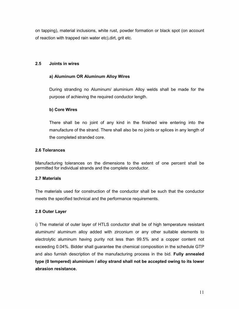
on tapping), material inclusions, white rust, powder formation or black spot (on account
of reaction with trapped rain water etc),dirt, grit etc.
2.5 Joints in wires
a) Aluminum OR Aluminum Alloy Wires
During stranding no Aluminum/ aluminium Alloy welds shall be made for the
purpose of achieving the required conductor length.
b) Core Wires
There shall be no joint of any kind in the finished wire entering into the
manufacture of the strand. There shall also be no joints or splices in any length of
the completed stranded core.
2.6 Tolerances
Manufacturing tolerances on the dimensions to the extent of one percent shall be permitted for individual strands and the complete conductor.
2.7 Materials
The materials used for construction of the conductor shall be such that the conductor
meets the specified technical and the performance requirements.
2.8 Outer Layer
i) The material of outer layer of HTLS conductor shall be of high temperature resistant
aluminum/ aluminum alloy added with zirconium or any other suitable elements to
electrolytic aluminum having purity not less than 99.5% and a copper content not
exceeding 0.04%. Bidder shall guarantee the chemical composition in the schedule GTP
and also furnish description of the manufacturing process in the bid. Fully annealed
type (0 tempered) aluminium / alloy strand shall not be accepted owing to its lower
abrasion resistance.
12
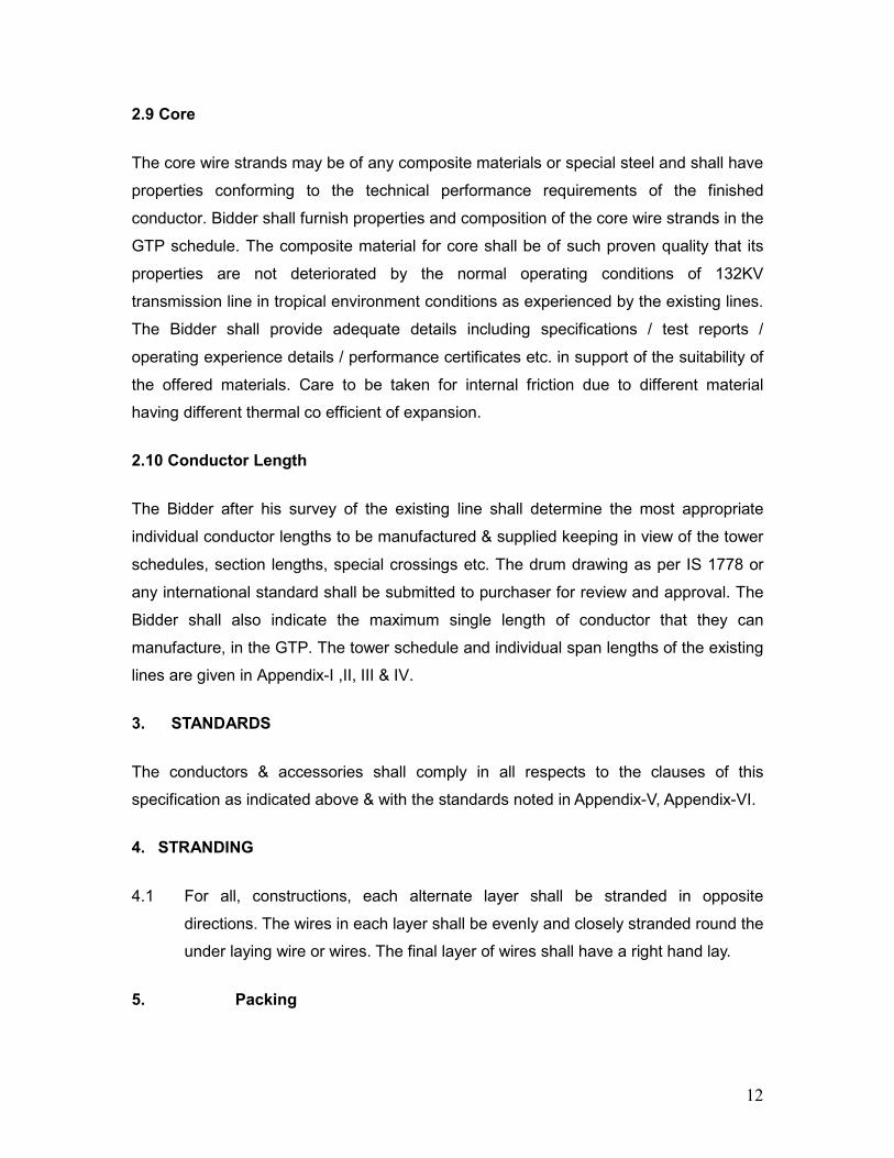
2.9 Core
The core wire strands may be of any composite materials or special steel and shall have
properties conforming to the technical performance requirements of the finished
conductor. Bidder shall furnish properties and composition of the core wire strands in the
GTP schedule. The composite material for core shall be of such proven quality that its
properties are not deteriorated by the normal operating conditions of 132KV
transmission line in tropical environment conditions as experienced by the existing lines.
The Bidder shall provide adequate details including specifications / test reports /
operating experience details / performance certificates etc. in support of the suitability of
the offered materials. Care to be taken for internal friction due to different material
having different thermal co efficient of expansion.
2.10 Conductor Length
The Bidder after his survey of the existing line shall determine the most appropriate
individual conductor lengths to be manufactured & supplied keeping in view of the tower
schedules, section lengths, special crossings etc. The drum drawing as per IS 1778 or
any international standard shall be submitted to purchaser for review and approval. The
Bidder shall also indicate the maximum single length of conductor that they can
manufacture, in the GTP. The tower schedule and individual span lengths of the existing
lines are given in Appendix-I ,II, III & IV.
3. STANDARDS
The conductors & accessories shall comply in all respects to the clauses of this
specification as indicated above & with the standards noted in Appendix-V, Appendix-VI.
4. STRANDING
4.1 For all, constructions, each alternate layer shall be stranded in opposite
directions. The wires in each layer shall be evenly and closely stranded round the
under laying wire or wires. The final layer of wires shall have a right hand lay.
5. Packing
13
5.1 The conductor shall be supplied in non-returnable, strong, wooden/painted steel/hybrid (painted steel cum wood) drums provided with lagging of adequate strength, constructed to protect the conductor against all damage and displacement during transit, storage and subsequent handling and stringing operations in the field. The Supplier shall select suitable drums for supply of conductor and shall be responsible for any loss or damage to conductor and/or drum during transportation handling and storage due to improper selection of drum or packing.
5.2 The drums shall be suitable for wheel mounting and for letting off the conductor under a minimum controlled tension of the order of 5000 Kgf.
5.3 The Bidder should submit their proposed drum drawings along with the bid.
5.4 One conductor length only shall be wound on each drum.
5.5 The conductor ends shall be properly sealed and secured on the side of one of the flanges to avoid loosening of the conductor layers during transit and handling.
5.6 Marking
Each drum shall have the following information stenciled on it in indelible ink along with other essential data :
(a) Contract/Award letter number.
(b) Name and address of consignee.
(c) Manufacturer’s name and address.
(d) Drum number
(e) Size of conductor
(f) Length of conductor in meters
(g) Arrow marking for unwinding
(h) Position of the conductor ends
(i) Distance between outer-most Layer of conductor and the inner surface of lagging.
(k) Barrel diameter at three locations & an arrow marking at the location of the measurement.
(l) Number of turns in the outer most layer.
(m) Gross weight of drum after putting lagging.
(n) Tear weight of the drum without lagging.
(o) Net weight of the conductor in the drum.
(p) Dispatch instruction.
14
The above should be indicated in the packing list also.
5.7 Verification of Conductor Length
The Employer reserves the right to verify the length of conductor after unreeling at least ten (10) percent of the drums in a lot offered for inspection.
6. Tests and Standards
6.1 Type Tests
Type Tests on Stranded Conductor/ Stranded wire
The following tests should have conducted in last five year.
(i) On complete Conductor
a) DC resistance test on stranded conductor : As per Annexure-A
b) UTS test on stranded conductor : As per Annexure-A
c) Stress- Strain test on stranded conductor and core at room temperature
: IEC 1089
d) Stress-strain test on stranded conductor and core at elevated temperature As per Annexure-A
e) High temperature endurance & creep test on stranded conductor
: As per Annexure-A
f) Sheaves Test : As per Annexure-A
g) Axial Impact Test : As per Annexure-A
h) Crush Strength Test : As per Annexure-A
i) Torsional Ductility Test : As per Annexure-A
(ii) On Conductor Strand/core
a) Heat resistance test on Aluminium Alloy strands : As per Annexure-A
b) Bending test on core : As per Annexure-A
c) Compression test on core : As per Annexure-A
d) Coefficient of linear expansion on core/ core strands
: As per Annexure-A
If any of the above type tests have not been made, the supplier should furnish an undertaking with the bid that the test reports to be
15
furnished before offering call for acceptance test. Otherwise the EMD will be forfeited; the bidder will not be eligible to participate in future tenders of OPTCL.
6.2 Acceptance Tests
a) Visual and dimensional check on drum : As per Annexure-A
b) Visual check for joints scratches etc. and length measurement of conductor by rewinding
: As per Annexure-A
c) Dimensional check on core strands/composite core and Aluminium Alloy strands
: As per Annexure-A
d) Check for lay-ratios of various layers : As per Annexure-A
e) Galvanising test on core strands (if applicable)
: As per Annexure-A
f) aluminum thickness on aluminium clad wires (if applicable)
g) Torsion and Elongation tests on core strands/composite core
: As per Annexure-A
h) Breaking load test on core strands and Aluminium / Aluminium Alloy strands
: As per Annexure-A
i) Wrap test on core strands and conductor. : As per IEC:888 & IES:889
j) Minimum conductivity test on conductor strands.
: As per IEC : 889
k) Heat resistance test on Aluminium Alloy strands
: As per Annexure-A
l) Ageing test on filler (if applicable) m) Minimum conductivity test on core
strands( if applicable) : As per Annexure-A
n) Dimentional check on conductor Note: All the above tests except (j) shall be carried out on Aluminium /
Aluminium Alloy and core strands after stranding only.
6.3 Routine Test
a) Check to ensure that the joints are as per Specification
b) Check that there are no cuts, fins etc., on the strands.
c) Check that drums are as per Specification
d) All acceptance tests as mentioned above to be carried out on each coil
16
6.4 Tests During Manufacture
a) Chemical analysis of zinc used for galvanizing ( if applicable) : As per Annexure-A
b) Chemical analysis of Aluminium alloy used for making Aluminium Alloy strands
: As per Annexure-A
c) Chemical analysis of core strands/composite core
: As per Annexure-A
6.5 Test Reports
6.5.1 Record of routine test reports shall be maintained by the Supplier at his works for periodic inspection by the Employer’s representative.
6.5.2 Test Certificates of tests during manufacture shall be maintained by the Supplier. These shall be produced for verification as and when desired by the Employer.
6.6 Inspection
6.6.1 The Employer’s representative shall at all times be entitled to have access to the works and all places of manufacture, where conductor shall be manufactured and representative shall have full facilities for unrestricted inspection of the Supplier’s works, raw materials and process of manufacture for conducting necessary tests as detailed herein.
6.6.2 The Supplier shall keep the Employer informed in advance of the time of starting and of the progress of manufacture of conductor in its various stages so that arrangements can be made for inspection.
6.6.3 No material shall be dispatched from its point of manufacture before it has been satisfactorily inspected and tested, unless the inspection is waived off by the Employer in writing. In the latter case also the conductor shall be dispatched only after satisfactory testing for all tests specified herein have been completed.
6.6.4 The acceptance of any quantity of material shall in no way relieve the Supplier of any of his responsibilities for meeting all requirements of the Specification, and shall not prevent subsequent rejection it such material is later found to be defective.
6.7 Test Facilities
6.7.1 The following additional test facilities shall be available at the Supplier’s works:
a) Calibration of various testing and measuring equipment including tensile testing machine, resistance measurement facilities, burette, thermometer, barometer etc.
b) Standard resistance for calibration of resistance bridges.
c) Finished conductor shall be checked for length verification and surface finish on separate rewinding machine at reduced speed (variable from 8 to 16 meters per minute). The rewinding facilities
17
shall have appropriate clutch system and free of vibrations, jerks etc. with traverse laying facilities.
6.8 Standards
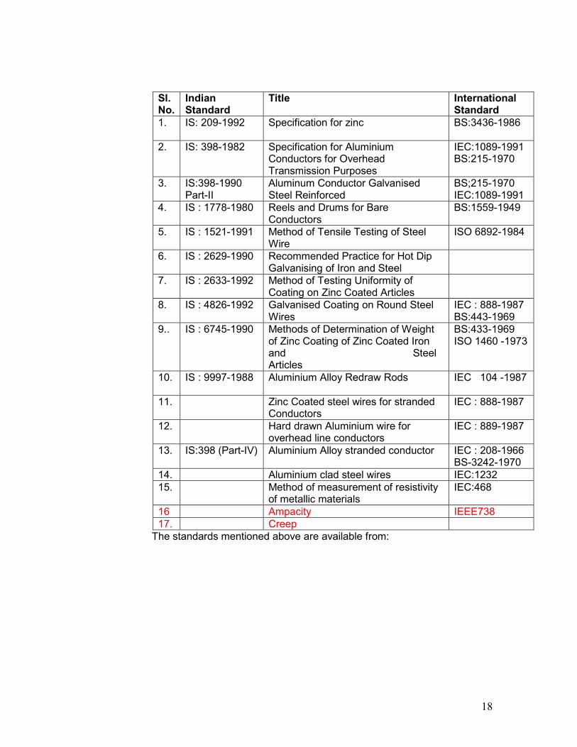
6.8.1 The conductor shall conform to the following Indian/International Standards, which shall mean latest revisions, with amendments/changes adopted and published, unless specifically stated otherwise in the Specification.
6.8.2 In the event of the supply of conductor conforming to standards other than specified, the Bidder shall confirm in his bid that these standards are equivalent to those specified. In case of award, salient features of comparison between the standards proposed by the Supplier and those specified in this document will be provided by the Supplier to establish their equivalence.
18
Sl. No.
Indian Standard
Title International Standard
1. IS: 209-1992 Specification for zinc BS:3436-1986
2. IS: 398-1982 Specification for Aluminium Conductors for Overhead Transmission Purposes
IEC:1089-1991 BS:215-1970
3. IS:398-1990 Part-II
Aluminum Conductor Galvanised Steel Reinforced
BS;215-1970 IEC:1089-1991
4. IS : 1778-1980 Reels and Drums for Bare Conductors
BS:1559-1949
5. IS : 1521-1991 Method of Tensile Testing of Steel Wire
ISO 6892-1984
6. IS : 2629-1990 Recommended Practice for Hot Dip Galvanising of Iron and Steel
7. IS : 2633-1992 Method of Testing Uniformity of Coating on Zinc Coated Articles
8. IS : 4826-1992 Galvanised Coating on Round Steel Wires
IEC : 888-1987 BS:443-1969
9.. IS : 6745-1990 Methods of Determination of Weight of Zinc Coating of Zinc Coated Iron and Steel Articles
BS:433-1969 ISO 1460 -1973
10. IS : 9997-1988 Aluminium Alloy Redraw Rods IEC 104 -1987
11. Zinc Coated steel wires for stranded Conductors
IEC : 888-1987
12. Hard drawn Aluminium wire for overhead line conductors
IEC : 889-1987
13. IS:398 (Part-IV) Aluminium Alloy stranded conductor IEC : 208-1966 BS-3242-1970
14. Aluminium clad steel wires IEC:1232 15. Method of measurement of resistivity
of metallic materials IEC:468
16 Ampacity IEEE738 17. Creep
The standards mentioned above are available from:

19
Reference Abbreviation
Name and Address
BS British Standards, British Standards Institution 101, Pentonvile Road, N - 19-ND UK
IEC/CISPR International Electro technical Commission, Bureau Central de la Commission, electro Technique international, 1 Rue de verembe, Geneva SWITZERLAND
BIS/IS Beureau Of Indian Standards. Manak Bhavan, 9, Bahadur Shah Zafar Marg, New Delhi - 110001. INDIA
ISO International Organisation for Standardization. Danish Board of Standardization Danish Standardizing Sraat, Aurehoegvej-12 DK-2900, Heeleprup, DENMARK.
NEMA National Electric Manufacture Association, 155, East 44th Street. New York, NY 10017 U.S.A.

20
7. GUARANTEED TECHNICAL PARTICULARS The bidder shall fill in the guaranteed technical particulars in the Performa below and
submit the same with his tender, without which bid will not be considered.
GUARANTEED TECHNICAL PARTICULARS OF HTLS CONDUCTOR
Sl. Description Unit Value guaranteed by the Bidder
1. Name of Manufacturer
2. Address of Manufacturer
3. Name of the conductor
4. Construction of conductor/
Designation of conductor as per
IEC:61089
5. Particulars of Raw Material
5.1 Outer Layers
a) Type of conductor strand.
b) Chemical composition of Conductor strand .
i) ---------- %
ii) ---------- %
iii) ---------- %
iv) --------- %
v) --------- %
5.2 Inner Core
a) Material of core
b) Chemical composition of core
i) ---------- %
ii) ---------- %
iii) ---------- %
iv) --------- %
v) --------- %
vi) -------- %
6. Outer Aluminium Alloy Strand after Stranding
6.1 Number of outer layers Nos.
6.2 Diameter mm
a) Nominal mm
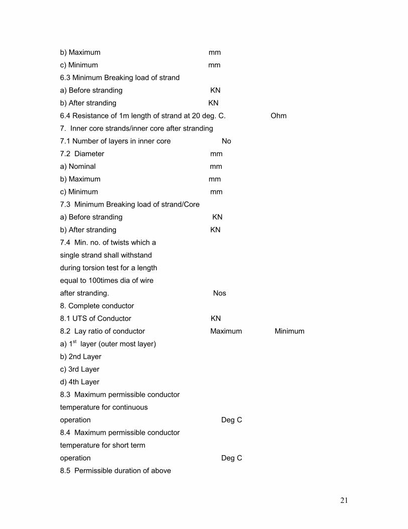
21
b) Maximum mm
c) Minimum mm
6.3 Minimum Breaking load of strand
a) Before stranding KN
b) After stranding KN
6.4 Resistance of 1m length of strand at 20 deg. C. Ohm
7. Inner core strands/inner core after stranding
7.1 Number of layers in inner core No
7.2 Diameter mm
a) Nominal mm
b) Maximum mm
c) Minimum mm
7.3 Minimum Breaking load of strand/Core
a) Before stranding KN
b) After stranding KN
7.4 Min. no. of twists which a
single strand shall withstand
during torsion test for a length
equal to 100times dia of wire
after stranding. Nos
8. Complete conductor
8.1 UTS of Conductor KN
8.2 Lay ratio of conductor Maximum Minimum
a) 1st layer (outer most layer)
b) 2nd Layer
c) 3rd Layer
d) 4th Layer
8.3 Maximum permissible conductor
temperature for continuous
operation Deg C
8.4 Maximum permissible conductor
temperature for short term
operation Deg C
8.5 Permissible duration of above
22
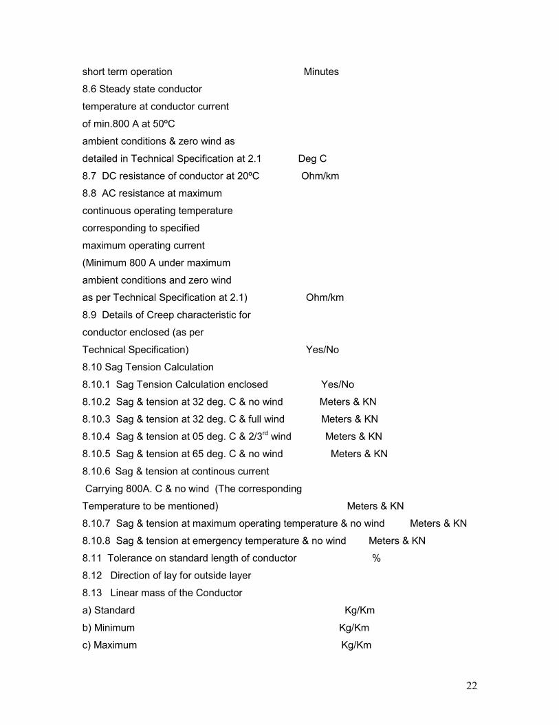
short term operation Minutes
8.6 Steady state conductor
temperature at conductor current
of min.800 A at 50ºC
ambient conditions & zero wind as
detailed in Technical Specification at 2.1 Deg C
8.7 DC resistance of conductor at 20ºC Ohm/km
8.8 AC resistance at maximum
continuous operating temperature
corresponding to specified
maximum operating current
(Minimum 800 A under maximum
ambient conditions and zero wind
as per Technical Specification at 2.1) Ohm/km
8.9 Details of Creep characteristic for
conductor enclosed (as per
Technical Specification) Yes/No
8.10 Sag Tension Calculation
8.10.1 Sag Tension Calculation enclosed Yes/No
8.10.2 Sag & tension at 32 deg. C & no wind Meters & KN
8.10.3 Sag & tension at 32 deg. C & full wind Meters & KN
8.10.4 Sag & tension at 05 deg. C & 2/3rd wind Meters & KN
8.10.5 Sag & tension at 65 deg. C & no wind Meters & KN
8.10.6 Sag & tension at continous current
Carrying 800A. C & no wind (The corresponding
Temperature to be mentioned) Meters & KN
8.10.7 Sag & tension at maximum operating temperature & no wind Meters & KN
8.10.8 Sag & tension at emergency temperature & no wind Meters & KN
8.11 Tolerance on standard length of conductor %
8.12 Direction of lay for outside layer
8.13 Linear mass of the Conductor
a) Standard Kg/Km
b) Minimum Kg/Km
c) Maximum Kg/Km
23
8.14 Standard length of conductor KM
8.15 Maximum length of conductor
that can be offered as single length KM
9.0 Drum is as per specification Yes/No
10.0 Accessories as per specification/standards Yes/No
Date: (Signature)……………………………
Place: (Printed Name)……………………….
(Designation)………………………….
(Common Seal)……………………….
8. SAG TENSION CHARTS AND SAG TEMPLATES
The contractor shall supply six copies of sag tension charts and sag templates each in
respect of the conductor. The contractor shall also supply sag template in celluloid,
which shall be subject to the approval by the owner and without involving any extra
charges. The sag template will be used for changing the tower positions in future.
9. ACCESSORIES
The Bidder after his survey of the existing line shall determine the quantity and type of
the accessories required for the turnkey job, which are to be supplied by them. These
accessories should be suitable for the supplied conductor for its entire operating range
without degradation of mechanical, metallurgical and electrical properties. The steady
state temperature of hardware and accessories must not exceed 90°C during no wind
and 50°C ambient temperature at minimum 800Amp load. The contractor shall be
responsible for satisfactory performance of complete conductor, hardware and
accessories, offered by him, for continuous operation at temperatures corresponding to
various conditions stipulated at 2.2 of this technical specification.
9.1 Design of Hardware & accessories should be compatible with the supplied HTLS
conductor and existing insulators & structures.
24
TECHNICAL SPECIFICATIONS FOR HARDWARE FITTINGS &
ACCESSORIES FOR HTLS CONDUCTOR.
9.1.1 Technical Description of Hardware Fittings 9.1.2 General
This section details technical particulars of fittings viz. suspension clamps and compression type dead end clamps for the HTLS Conductor to be supplied by the bidder. Each fitting shall be supplied complete in all respects.
9.1.3 The fittings shall be suitable for attachment to suspension and tension insulator strings along with hardware fittings and shall include 2.5 % extra fasteners and Aluminium filler plugs. Indicative drawings of complete insulator strings along with hardware fittings as well as indicative drawings for suspension clamps and dead end clamps are enclosed with this specification. The supplier shall be responsible for satisfactory performance of complete conductor system along with fittings offered by them for continuous operation at the maximum temperature specified by them for the conductor.
9.1.4 Corona and RI Performance
Sharp edges and scratches on all the hardware fittings shall be avoided. All surfaces must be clean, smooth, without cuts and abrasions or projections. The Supplier shall be responsible for satisfactory corona and radio interference performance of the materials offered by him.
9.1.5 Maintenance
The hardware fittings offered shall be suitable for employment of hot line maintenance technique so that usual hot line operations can be carried out with ease, speed and safety. The technique adopted for hot line maintenance shall be generally bare hand method & hot stick method.
9.1.6 Split Pins Split pins shall be used with bolts & nuts.
9.1.7 Suspension Assembly
9.1.7.1 The suspension assembly shall be suitable for the HTLS Conductor, the bidder intend to supply. The technical details of the conductor shall be as proposed by the bidder.
9.1.7.2 The suspension assembly shall include either free centre type suspension clamp along with standard preformed armour rods or armour grip suspension clamp
9.1.7.3 The suspension clamp along with standard preformed armour rods set shall be designed to have maximum mobility in any direction and minimum moment of inertia so as to have minimum stress on the conductor in the case of oscillation of the same.
25
9.1.7.4 The suspension clamp suitable for various type of Conductor along with standard preformed armour rods/armour grip suspension clamp set shall have a slip strength between 8% to 15% of the UTS of the conductor.
9.1.7.5 The suspension clamp shall be designed for continuous operation at the temperature specified by the bidder for conductor.
9.1.7.6 The suspension assembly shall be designed, manufactured and finished to give it a suitable shape, so as to avoid any possibility of hammering between suspension assembly and conductor due to vibration. The suspension assembly shall be smooth without any cuts, grooves, abrasions, projections, ridges or excrescence which might damage the conductor.
9.1.7.7 The suspension assembly/clamp shall be designed so that it shall minimise the static & dynamic stress developed in the conductor under various loading conditions as well as during wind induced conductor vibrations. It shall also withstand power arcs & have required level of Corona/RIV performance.
9.1.7.8 The magnetic power loss shall not be more than 4 watts per suspension clamp, at designed rated sub-conductor current of 800 amperes.
9.1.8 Free Centre Type Suspension Clamp
For the Free Centre Suspension Clamp seat shall be smoothly rounded and curved into a bell mouth at the ends. The lip edges shall have rounded bead. There shall be at least two U-bolts for tightening of clamp body and keeper pieces together.
9.1.9 Standard Preformed Armour Rod Set
9.1.9.1 The Preformed Armour Rods Set shall be used to minimize the stress developed in the sub-conductor due to different static and dynamic loads because of vibration due to wind, slipping of conductor from the suspension clamp as a result of unbalanced conductor tension in adjacent spans and broken wire condition. It shall also withstand power arcs. chafing and abrasion from suspension clamp and localized heating effect due to magnetic power losses from suspension clamps as well as resistance losses of the conductor.
9.1.9.2 The preformed armour rods set shall have right hand lay and the inside diameter of the helics shall be less than the outside diameter of the conductor to have gentle but permanent grip on the conductor. The surface of the armour rod when fitted on the conductor shall be smooth and free from projections, cuts and abrasions etc.
9.1.9.3 The pitch length of the rods shall be determined by the Bidder but shall be less than that of the outer layer of conductor and the same shall be accurately controlled to maintain uniformity and consistently reproducible characteristic wholly independent of the skill of linemen.
9.1.9.4 The length of each rod shall not be less than 1930 ± 25 mm and diameter shall not be less than 6.35 + 0.10 mm. The tolerance in length
26
of the rods in complete set should be within 13 mm between the longest and shortest rod. The ends of armour rod shall be parrot billed.
9.1.9.5 The number of armour rods in each set shall be eleven. Each rod shall be marked in the middle with paint for easy application on the line.
9.1.9.6 The armour rod shall not loose their resilience even after five applications.
The conductivity of each rod of the set shall not be less than 40% of the conductivity of the International Annealed Copper Standard (IACS).
9.1.10 Armour Grip Suspension Clamp
9.1.10.1 The armour grip suspension clamp shall comprise of retaining strap, support housing, elastomer inserts with aluminium reinforcements and AGS preformed rod set.
9.1.10.2 Elastomer insert shall be resistant to the effects of temperature up to maximum conductor temperature guaranteed by the bidder corresponding to peak current, Ozone, ultraviolet radiations and other atmospheric contaminants likely to be encountered in service. The physical properties of the elastomer shall be of approved standard. It shall be electrically shielded by a cage of AGS performed rod set. The elastomer insert shall be so designed that the curvature of the AGS rod shall follow the contour of the neoprene insert.
9.1.10.3 The length of the AGS preformed rods shall be such that it shall ensure sufficient slipping strength and shall not introduce unfavourable stress on the conductor under all operating conditions. However the length of AGS preformed rods shall not be less than 1760 + 16 mm for HTLS Conductor.
9.1.11 Dead end Assembly
9.1.11.1 The dead end assembly shall be suitable for the proposed HTLS Conductor.
9.1.11.2 The dead end assembly shall be of compression type with provision for compressing jumper terminal at one end. The angle of jumper terminal to be mounted should be 30° with respect to the vertical line. The area of bearing surface on all the connections shall be sufficient to ensure positive electrical and mechanical contact and avoid local heating due to I2R losses. The resistance of the clamp when compressed on Conductor shall not be more than 75% of the resistance of equivalent length of Conductor.
9.1.11.3 Die compression areas shall be clearly marked on each dead-end assembly designed for continuous die compressions and shall bear the words ‘COM PRESS FIRST’ suitably inscribed near the point on each assembly where the compression begins. If the dead end assembly is designed for intermittent die compressions it shall bear identification marks ‘COMPRESSION ZONE’ AND ‘NON-COMPRESSION ZONE’ distinctly with arrow marks showing the direction of compressions and knurling marks showing the end of the zones. Tapered aluminium filler plugs shall also be provided at the line of demarcation between
27
compression & non-compression zone. The letters, number and other markings on the finished clamp shall be distinct and legible. The dimensions of dead end assembly before & after compression along with tolerances shall be shall be guaranteed in the relevant schedules of the bid and shall be decided by the manufacturer so as to suit the conductor size & conform to electrical & mechanical requirement stipulated in the specification.
9.1.11.4 The assembly shall not permit slipping of, damage to, or failure of the complete conductor or any part there of at a load less than 95% of the ultimate tensile strength of the conductor.
9.1.12 Fasteners : Bolts, Nuts and Washers
9.1.12.1 All bolts and nuts shall conform to IS 6639. All bolts and nuts shall be galvanised as per IS 1367 (Part-13)/IS 2629. All bolts and nuts shall have hexagonal heads, the heads being forged out of solid truly concentric, and square with the shank, which must be perfectly straight.
9.1.12.2 Bolts upto M16 and having length upto 10 times the diameter of the bolt should be manufactured by cold forging and thread rolling process to obtain good and reliable mechanical properties and effective dimensional control. The shear strength of bolt for 5.6 grade should be 310 MPa minimum as per IS 12427. Bolts should be provided with washer face in accordance with IS 1363 (Part-1) to ensure proper bearing.
9.1.12.3 Nuts should be double chamfered as per the requirement of IS 1363 Part-III 1984. It should be ensured by the manufacturer that nuts should not be over tapped beyond 0.4 mm oversize on effective diameter for size upto M16.
9.1.12.4 Fully threaded bolts shall not be used. The length of the bolt shall be such that the threaded portion shall not extend into the place of contact of the component parts.
9.1.12.5 All bolts shall be threaded to take the full depth of the nuts and threaded enough to permit the firm gripping of the component parts but no further. It shall be ensured that the threaded portion of the bolt protrudes not less than 3 mm and not more than 8 mm when fully tightened. All nuts shall fit and tight to the point where shank of the bolt connects to the head.
9.1.12.6 Flat washers and spring washers shall be provided wherever necessary and shall be of positive lock type. Spring washers shall be electro-galvanized. The thickness of washers shall conform to IS:2016.
9.1.12.7 The Contractor shall furnish bolt schedules giving thickness of components connected. the nut and the washer and the length of shank and the threaded portion of bolts and size of holes and any other special details of this nature.
9.1.12.8 To obviate bending stress in bolt, it shall not connect aggregate thickness more than three time its diameter.
28
9.1.12.9 Bolts at the joints shall be so staggered that nuts may be tightened with spanners without fouling.
9.1.12.10 To ensure effective in-process Quality control it is essential that the manufacturer should have all the testing facilities for tests like weight of zinc coating, shear strength, other testing facilities etc, in-house. The manufacturer should also have proper Quality Assurance system which should be in line with the requirement of this specification and IS-.14000 services Quality System standard.
9.1.12.11 Fasteners of grade higher than 8.8 are not to be used and minimum grade for bolt shall be 5.6.
9.1.13 Materials
The materials of the various components shall be as specified hereunder. The Bidder shall indicate the material proposed to be used for each and every component of hardware fittings stating clearly the class, grade or alloy designation of the material, manufacturing process & heat treatment details and the reference standards.
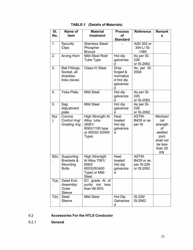
9.1.13.1 The details of materials for different component are listed as in Table No-1.
9.1.14 Workmanship
9.1.14.1 All the equipment shall be of the latest design and conform to the best modern practices adopted in the Extra High Voltage field. The Bidder shall offer only such equipment as guaranteed by him to be satisfactory and suitable for 132 kV transmission lines and will give continued good performance.
9.1.14.2 High current, heat rise test shall be conducted by the supplier to determine the maximum temperature achieved in different components of fittings under simulated service condition corresponding to continuous operation of conductor at rated maximum temperature. The material of the components should be suitable for continued good performance corresponding to these maximum temperatures. The supplier shall submit relevant type/performance test certificates as per applicable standards/product specifications tp confirm suitability of the offered material.
9.1.14.3 The design, manufacturing process and quality control of all the materials shall be such as to give the specified mechanical rating, highest mobility, elimination of sharp edges and corners to limit corona and radio-interference, best resistance to corrosion and a good finish.
9.1.14.4 All ferrous parts including fasteners shall be hot dip galvanized, after all machining has been completed. Nuts may, however, be tapped (threaded) after galvanizing and the threads oiled. Spring washers shall be electro galvanized. The bolt threads shall be undercut to take care of the increase in diameter due to galvanizing. Galvanizing shall he done in accordance with IS 2629 / IS 1367 (Part-13) and shall satisfy the tests mentioned in IS 2633. Fasteners shall withstand four dips while spring
29
washers shall withstand three dips of one minute duration in the standard Preece test. Other galvanized materials shall have a minimum average coating of zinc equivalent to 600 gm/sq.m., shall be guaranteed to withstand at least six successive dips each lasting one (1) minute under the standard preece test for galvanizing.
9.1.14.5 The zinc coating shall be perfectly adherent. of uniform thickness, smooth, reasonably bright. continuous and free from imperfections such as flux,. ash rust, stains, bulky white deposits and blisters. The zinc used for galvanizing shall be grade Zn 99.95 as per IS:209.
9.1.14.6 In case of casting, the same shall be free from all internal defects like shrinkage, inclusion, blow holes, cracks etc. Pressure die casting shall not be used for casting of components with thickness more than 5 mm.
9.1.14.7 All current carrying parts shall be so designed and manufactured that contact resistance is reduced to minimum.
9.1.14.8 No equipment shall have sharp ends or edges, abrasions or projections and cause any damage to the conductor in any way during erection or during continuous operation which would produce high electrical and mechanical stresses in normal working. The design of adjacent metal parts and mating surfaces shall be such as to prevent corrosion of the contact surface and to maintain good electrical contact under service conditions.
9.1.14.9 All the holes shall be cylindrical, clean cut and perpendicular to the plane of the material. The periphery of the holes shall be free from burrs.
9.1.14.10 All fasteners shall have suitable corona free locking arrangement to guard against vibration loosening.
9.1.14.11 Welding of aluminium shall be by inert gas shielded tungesten arc or inert gas shielded metal arc process. Welds shall be clean, sound, smooth, uniform without overlaps, properly fused and completely sealed. There shall be no cracks, voids incomplete penetration, incomplete fusion, under-cutting or inclusions. Porosity shall be minimised so that mechanical properties of the aluminium alloys are not affected. All welds shall be properly finished as per good engineering practices.
9.1.15 Bid Drawings
9.1.15.1 The Bidder shall furnish full description and illustrations of materials offered.
9.1.15.2 Fully dimensioned drawings of the hardwares and their component parts shall be furnished in three (3) copies along with the bid. Weight, material and fabrication details of all the components should be included in the drawings.
All drawings shall be identified by a drawing number and contract number. All drawings shall be neatly arranged. All drafting & lettering shall be legible. The minimum size of lettering shall be 3 mm. All dimensions & dimensional tolerances shall be mentioned in mm.
The drawings shall include :
30
(i) Dimensions and dimensional tolerance.
(ii) Material, fabrication details including any weld details & any specified finishes & coatings. Regarding material designation & reference of standards are to be indicated.
(iii) Catalogue No.
(iv) Marking
(v) Weight of assembly
(vi) Installation instructions
(vii) Design installation torque for the bolt or cap screw.
(viii) Withstand torque that may be applied to the bolt or cap screw without failure of component parts.
(ix) The compression die number with recommended compression pressure.
(x) All other relevant terminal details.
9.1.15.3 After placement of award, the Contractor shall submit fully dimensioned drawing including all the components in three (3) copies to the Owner for approval. After getting approval from the Owner and successful completion of all the type tests, the Contractor shall submit ten (10) more copies of the same drawings to the Owner for further distribution and field use at Owner’s end.
31
TABLE-1 (Details of Materials)
Sl. No.
Name of item
Material treatment
Process of
Standard
Reference Remarks
1. Security Clips
Stainless Steel/ Phospher Bronze
- AISI 302 or 304-L/ IS-
1385
2. Arcing Horn Mild Steel Rod/ Tube Type
Hot dip galvanised
As per IS-226 or IS-2062
3. Ball Fittings, Socket, all shackles links cleves
Class-IV Steel Drop forged & normalized Hot dip galvanised
As per IS: 2004
4. Yoke Plate Mild Steel Hot dip galvanized
As per IS-226 or IS-2062
5. Sag Adjustment plate
Mild Steel Hot dip galvanized
As per IS-226 or IS-2062
6(a).
Corona Control ring/ Grading ring
High Strength Al. Alloy tube (6061/ 6063/1100 type or 65032/ 63400 Type)
Heat treated Hot dip galvanized
ASTM-B429 or as per IS
Mechanical
strength of
welded joint
shall not be less than 20
KN 6(b).
Supporting Brackets & Mounting Bolts
High Strentgth Al Alloy 7061/ 6063/ 65032/63400 Type) or Mild Steel
Heat treated Hot dip galvanized
ASTM-B429 or as per IS:226 or IS:2062
7(a).
Dead End Assembly: Outer Sleeve
EC grade Al of purity not less than 99.50%
7(b).
Steel Sleeve
Mild Steel Hot Dip Galvanised
IS:226/ IS-2062
.
9.2 Accessories For the HTLS Conductor
9.2.1 General
32
This portion details the technical particulars of the accessories for Conductor.
9.2.2 2.5% extra fasteners, filler plugs and retaining rods shall be provided.
9.2.3 The supplier shall be responsible for satisfactory performance of complete conductor system along with accessories offered by him for continuous operation at temperature specified for the HTLS Conductor.
9.2.4 Mid Span Compression Joint
9.2.4.1 Mid Span Compression Joint shall be used for joining two lengths of conductor. The joint shall have a resistively less than 75% of the resistivity of equivalent length of conductor. The joint shall not permit slipping off, damage to or failure of the complete conductor or any part thereof at a load less than 95% of the ultimate tensile strength of the conductor. It must be able to withstand the continuous design temperature of conductor.
9.2.4.2 The dimensions of mid span compression joint before & after compression alongwith tolerances shall be shall be guaranteed in the relevant schedules of the bid and shall be decided by the manufacturer so as to suit the conductor size & conform to electrical & mechanical requirement stipulated in the specification.
9.2.5 Connector
Connector of compression type shall be used for jumper connection at tension tower . It shall be manufactured out of 99.5% pure aluminium / aluminium alloy and shall be strong enough to withstand normal working loads as well as able to withstand the continuous maximum operating temperature of conductor. The connector shall have a resistivity across jumper less than 75% resistivity of equivalent length of conductor. The connector shall not permit slipping off, damage to or failure of complete conductor . The welded portions shall be designed for 20 kN axial tensile load. Leg sleeve of connector should be kept at an angle of 15 deg. from vertical and horizontal plane of the conductor in order to minimize jumper pull at the welded portion . The dimensions of connector along with tolerances shall be shall be guaranteed in the relevant schedules of the bid and shall be decided by the manufacturer so as to suit the conductor size & conform to electrical & mechanical requirement stipulated in the specification.
9.2.6 Repair Sleeve
Repair Sleeve of compression type shall be used to repair conductor with not more than two strands broken in the outer layer. The sleeve shall be manufactured from 99.5% pure aluminium / aluminium alloy and shall have a smooth surface. It shall be able to withstand the continuous maximum operating temperature of conductor The repair sleeve shall comprise of two pieces with a provision of seat for sliding of the keeper piece. The edges of the seat as well as the keeper piece shall be so rounded that the conductor strands are not damaged during installation. The dimensions of Repair sleeve alongwith tolerances shall be
33
guaranteed in the relevant schedules of the bid and shall be decided by the manufacturer so as to suit the conductor size & conform to electrical & mechanical requirement stipulated in the specification.
9.2.7 Vibration Damper
9.2.7.1 Vibration dampers of 4R-stockbridge type with four (4) different resonances spread within the specified aeolian frequency band width corresponding to wind speed of 1 m/s to 7 m/s are installed in the existing line at suspension and tension points on each conductor in each span alongwith bundle spacers to damp out aeolian vibration as well as sub- span oscillations,. One damper minimum on each side per sub-conductor for suspension points and two dampers minimum on each side per sub-conductor for tension points has been used for a ruling design span of 320 meters.
9.2.7.2 The bidder shall offer damping system including Stockbridge type dampers and bundle spacers for HTLS conductor for its protection from wind induced vibrations which could cause conductor fatigue /strand breakage near a hardware attachment,such as suspension clamps. Alternate damping systems with proven design offering equivalent or better performance also shall be accepted provided the manufacturer meets the qualifying requirements stipulated in the Specifications. Relevant technical documents including type test reports to establish the technical suitability of alternate systems shall be furnished by the Bidder alongwith the bid.
The damper shall be designed to have minimum 4 nos of resonance frequencies to facilitate dissipation of vibration energy through interstrand friction of the messanger cable and shall be effective in reducing vibration over a wide frequency range ( depending upon conductor dia ) or wind velocity range specified above. The vibration damper shall meet the requirement of frequency or wind velocity range and also have machanical impedence closely matched with the offered HTLS conductor. The vibration dampers shall be installed at suitable positions to ensure damping effectiveness across the frequency range. The power dissipation of the vibration dampers shall exeed the wind power so that the vibration level on the conductor is reduced below its endurence limit ie 150 micro strain. The bidder shall clearly indicate the method for evaluating performance of dampers including analytrical and laboratory test methods. The bidder shall indicate the the type tests to evaluate the performance of offered damping system .
9.2.7.3 The clamp of the vibration damper shall be made of high strength aluminium alloy of type LM-6. It shall be capable of supporting the damper and prevent damage or chafing of the conductor during erection or continued operation. The clamp shall have smooth and permanent grip to keep the damper in position on the conductor without damaging the strands or causing premature fatigue failure of the conductor under the clamp. The clamp groove shall be in uniform contact with the conductor over the entire clamping surface except for the rounded edges. The groove of the clamp body and clamp cap shall be smooth, free from
34
projections, grit or other materials which could cause damage to the conductor when the clamp is installed. Clamping bolts shall be provided with self locking nuts and designed to prevent corrosion of threads or loosening in service.
9.2.7.4 The messenger cable shall be made of high strength galvanised steel/stain less steel with a minimum strength of 135 kg/sqmm. It shall be of preformed and post formed quality in order to prevent subsequent droop of weight and to maintain consistent flexural stiffness of the cable in service.The messenger cable other than stainless steel shall be hot dip galvanised in accordance with the recommendations of IS:4826 for heavily coated wires.
9.2.7.5 The damper mass shall be made of hot dip galvanised mild steel/cast iron or a permanent mould cast zinc alloy. All castings shall be free from defects such as cracks, shrinkage, inclusions and blowholes etc. The surface of the damper masses shall be smooth.
9.2.7.6 The damper clamp shall be casted over the messenger cable and offer sufficient and permanent grip on it. The messenger cable shall not slip out of the grip at a load less than the mass pull-off value of the damper. The damper masses made of material other-than zinc alloy shall be fixed to the messenger cable in a suitable manner in order to avoid excessive stress concentration on the messenger cables which shall cause premature fatigue failure of the same. The messenger cable ends shall be suitably and effectively sealed to prevent corrosion. The damper mass made of zinc alloy shall be casted over the messenger cable and have sufficient and permanent grip on the messenger cable under all service conditions.
9.2.7.7 The damper assembly shall be so designed that it shall not introduce radio interference beyond acceptable limits.
9.2.7.8 The vibration damper shall be capable of being installed and removed from energised line by means of hot line technique. in addition, the clamp shall be capable of being removed and reinstalled on the conductor at the designated torque without shearing or damaging of fasteners.
9.2.7.9 The contractor must indicate the clamp bolt tightening torque to ensure that the slip strength of the clamp is maintained between 2.5 kN and 5 kN. The clamp when installed on the conductor shall not cause excessive stress concentration on the conductor leading to permanent deformation of the conductor strands and premature fatigue failure in operation.
9.2.7.10 The damper placement chart shall be submitted for spans ranging from 50 m to 320 m. Placement charts should be duly supported with relevant technical documents and sample calculations.
9.2.7.11 The damper placement charts shall include the following
(1) Location of the dampers for various combinations of spans and line tensions clearly indicating the number of dampers to be installed per conductor per span.
35
(2) Placement distances clearly identifying the extremities between which the distances are to be measured.
(3) Placement recommendation depending upon type of suspension clamps (viz Free centre type/Armour grip type etc.)
(4) The influence of mid span compression joints, repair sleeves & armour rods ( standard & AGS) in the placement of dampers.
9.2.8 Material and Workmanship
9.2.8.1 All the equipment shall be of the latest proven design and conform to the best modern practice adopted in the extra high voltage field. The Bidder shall offer only such equipment as guaranteed by him to be satisfactory and suitable for 132 kV transmission line application with HTLS conductors and will give continued good performance at all service conditions.
9.2.8.2 The design, manufacturing process and quality control of all the materials shall be such as to achieve requisite factor of safety for maximum working load, highest mobility, elimination of sharp edges and corners, best resistance to corrosion and a good finish.
9.2.8.3 High current, heat rise test shall be conducted by the supplier to determine the maximum temperature achieved in different components of fittings under simulated service condition corresponding to continuous operation of conductor at rated maximum temperature. The material of the components should be suitable for continued good performance corresponding to these maximum temperatures. The supplier shall submit relevant type/ performance test certificates as per applicable standards/product specifications tp confirm suitability of the offered material.
9.2.8.4 All ferrous parts shall be hot dip galvanised, after all machining has been completed. Nuts may, however, be tapped (threaded) after galvanising and the threads oiled. Spring washers shall be electro galvanised as per grade 4 of IS-1573. The bolt threads shall be undercut to take care of increase in diameter due to galvanising. Galvanising shall be’done in accordance with IS:2629/ IS-1367 (Part-13) and satisfy the tests mentioned in IS-2633. Fasteners shall withstand four dips while spring washers shall withstand three dips. Other galvanised materials shall have a minimum average coating of Zinc equivalent to 600 gm/sq.m and shall be guaranteed to withstand at least six dips each lasting one minute under the standard Preece test for galvanising unless otherwise specified.
9.2.8.5 The zinc coating shall be perfectly adherent, of uniform thickness, smooth, reasonably bright, continuous and free from imperfections such as flux, ash, rust stains, bulky white deposits and blisters. The zinc used for galvanising shall be of grade Zn 99.95 as per IS:209.
9.2.8.6 In case of castings, the same shall be free from all internal defects like shrinkage, inclusion, blow holes, cracks etc.
36
9.2.8.7 All current carrying parts shall be so designed and manufactured that contact resistance is reduced to minimum and localised heating phenomenon is averted.
9.2.8.8 No equipment shall have sharp ends or edges, abrasions or projections and shall not cause any damage to the conductor in any way during erection or during continuous operation which would produce high electrical and mechanical stresses in normal working. The design of adjacent metal parts and mating surfaces shall be such as to prevent corrosion of the contact surface and to maintain good electrical contact under all service conditions.
9.2.8.9 Particular care shall be taken during manufacture and subsequent handling to ensure smooth surface free from abrasion or cuts.
9.2.8.10 The fasteners shall conform to the requirements of IS:6639-1972. All fasteners and clamps shall have corona free locking arrangement to guard against vibration loosening.
9.2.9 Compression Markings
Die compression areas shall be clearly marked on each equipment designed for continuous die compressions and shall bear the words ‘COMPRESS FIRST’ ‘suitably inscribed on each equipment where the compression begins. If the equipment is designed for intermittent die compressions, it shall bear the identification marks ‘COMPRESSION ZONE’ and ‘NON-COMPRESSION ZONE’ distinctly with arrow marks showing the direction of compression and knurling marks showing the end of the zones. The letters, number and other markings on finished equipment shall be distinct and legible.
9.2.10 Bid Drawings
9.2.10.1 The Bidder shall furnish detailed dimensioned drawings of the equipments and all component parts. Each drawing shall be identified by a drawing number and Contract number. All drawings shall be neatly arranged. All drafting and lettering shall be legible. The minimum size of lettering shall be 3 mm. All dimensions and dimensional tolerances shall be mentioned in mm.
9.2.10.2 The drawings shall include
(i) Dimensions and dimensional tolerances
(ii) Material. fabrication details including any weld details and any specified finishes and coatings. Regarding material, designations and reference of standards are to be indicated.
(iii) Catalogue No.
(iv) Marking
(v) Weight of assembly
(vi) Installation instructions
(vii) Design installation torque for the bolt or cap screw
37
(viii) Withstand torque that may be applied to the bolt or cap screw without failure of component parts
(ix) The compression die number with recommended compression pressure.
(x) All other relevant technical details
9.2.10.3 Placement charts for spacer/spacer damper and damper
9.2.10.4 The above drawings shall be submitted with all the details as stated abcve alongwith the bid document. After the placement of award. the Contractor shall again submit the drawings in three copies to the Owner for approval. After Owner’s approval and successful completion of all type tests, 10 (ten) more sets of drawings shall be submitted to Owner for further distribution and field use at Owner’s end.
9.2.11 Tests and Standards
Type Tests (Type tests should have been completed during last five years)
9.2.11.1 On Suspension Clamp
a) Magnetic power loss test : As per Annexure-B
b) Clamp slip strength Vs torque test : As per Annexure-B
9.2.11.2 On Dead end Tension Assembly
a) Electrical resistance test for dead end Assembly : As per IS:2486-(Part-I)
b) Heating cycle test for dead end Assembly : As per IS:2486-(Part-I)
c) Slip strength test for dead end assembly : As per IS:2486-(Part-I)
9.2.11.3 Mid Span Compression Joint for Conductor
a) Chemical analysis of materials : As per Annexure-B
b) Electrical resistance test :As per IS:2121 (Part-II)
c) Heating cycle test :As per IS:2121 (Part-II)
d) Slip strength test : As per Annexure-B
e) Corona extinction voltage test (dry) : As per Annexure-B
f) Radio interference voltage test (dry) : As per Annexure-B
38
9.2.11.4 Repair Sleeve for Conductor
a) Chemical analysis of materials : As per Annexure-B
b) Corona extinction voltage test (dry) : As per Annexure-B
c) Radio interference voltage test (dry) : As per Annexure-B
9.2.11.5 Connector for Conductor
a) Chemical analysis of materials : As per Annexure-B
b) Electrical resistance test :As per IS:2121 (Part-II) Clause 6.5 & 6.6
c) Heating cycle test :As per IS:2121 (Part-II)
d) Axial tensile load test on welded portion : As per Annexure-B
e) Corona extinction voltage test (dry) : As per Annexure-B
f) Radio interference voltage test (dry) : As per Annexure-B
9.2.11.6 Vibration Damper for Conductor
a) Chemical analysis of materials : As per Annexure-B
b) Dynamic characteristics test* : As per Annexure-B
c) Vibration analysis : As per Annexure-B
d) Clamp slip test : As per Annexure-B
e) Fatigue tests : As per Annexure-B
f) Magnetic power loss test : As per Annexure-B
g) Corona extinction voltage test (dry) : As per Annexure-B
h) Radio interference voltage test (dry) : As per Annexure-B
i) Damper efficiency test : As per IS:9708
* Applicable for 4 R stockbridge dampers. For alternate type of vibration dampers (permitted as per clause 2.5.2), as an alternative to dynamic characteristic test, damper efficiency test as per IEEE-664 Power Manual may be proposed/ carried out by the supplier.
9.2.12 Acceptance Tests
39
9.2.12.1 On Both Suspension Clamp and Tension Assembly
a) Visual Examination : As per IS:2486-(Part-I)
b) Verification of dimensions : As per IS:2486-(Part-I)
c) Galvanising/Electroplating test : As per IS:2486-(Part-I)
d) Mechanical strength test of each component : As per Annexure-B
e) Mechanical Strength test of welded joint : As per Annexure-B
f) Chemical analysis, hardness tests, grain size, inclusion rating & magnetic particle inspection for forgings/castings
: As per Annexure-B
9.2.12.2 On Suspension Clamp only
a) Clamp Slip strength Vs Torque test for suspension clamp
: As per Annexure-B
b) Shore hardness test of elastomer cushion for AG suspension clamp
: As per Annexure-B
c) Bend test for armour rod set : As per IS:2121(Part-I), Clause 7.5,7,10 & 7.11
d) Resilience test for armour rod set : As per IS:2121(Part-I), Clause 7.5,7,10 & 7.11
e) Conductivity test for armour rods set : As per IS:2121(Part-I), Clause 7.5,7,10 & 7.11
9.2.12.3 On Tension Hardware Fittings only
a) Slip strength test for dead end assembly : As per IS:2486 (Part-I) Clause 5.4
d) Ageing test on filler (if applicable) : As per Annexure-C
9.2.12.4 On Mid Span Compression Joint for Conductor
a) Visual examination and dimensional verification : As per IS:2121 (Part-II), Clause 6.2, 6.3 7 6.7
40
b) Galvanising test : As per Annexure-C
c) Hardness test : As per Annexure-C
d) Ageing test on filler (if applicable) : As per Annexure-C
9.2.12.5 Connector for Conductor
a) Visual examination and dimensional verification : As per IS:2121 (Part-II)
b) Axial tensile load test for welded portion : As per Annexure-B
9.2.12.6 Repair Sleeve for Conductor
a) Visual examination and dimensional verification : As per IS:2121(Part-II) Clause 6.2, 6.3
9.2.12.7 Vibration Damper for Conductor
a) Visual examination and dimensional verification : As per IS:2121(Part-II) Clause 6.2, 6.3 7 6.7
b) Galvanising test : As per Annexure-C
(i) On damper masses : As per Annexure-C
ii) On messenger cable : As per Annexure-C
c) Verification of resonance frequencies : As per Annexure-C
d) Clamp slip test : As per Annexure-C
e) Clamp bolt torque test : As per Annexure-C
f) Strength of the messenger cable : As per Annexure-C
g) Mass pull off test : As per Annexure-C
h) Dynamic characteristics test* : As per Annexure-C
* Applicable for 4 R stockbridge dampers. For alternate type of vibration dampers (permitted as per clause 2.5.2), as an alternative to dynamic characteristic test, damper efficiency test as per IEEE-664 Power Manual may be proposed/ carried out by the supplier.
9.2.13 Routine Tests
9.2.13.1 For Hardware Fittings
a) Visual examination IS:2486-(Part-I)
41
b) Proof Load Test : As per Annexure-B
9.2.13.2 For conductor accessories
a) Visual examination and dimensional verification : As per IS:2121(Part-II) Clause 6.2, 6.3 7 6.7
9.2.13.3 Tests During Manufacture on all components as applicable
a) Chemical analysis of Zinc used for galvanising IS:2486-(Part-I)
b) Chemical analysis mechanical metallographic test and magnetic particle inspection for malleable castings
: As per Annexure-B
c) Chemical analysis, hardness tests and magnetic particle inspection for forging
: As per Annexure-B
If any of the above type tests have not been made, the supplier should furnish an undertaking with the bid that the test reports to be furnished before offering call for acceptance test. Otherwise the EMD will be forfeited; the bidder will not be eligible to participate in future tenders of OPTCL.
9.2.14 Co-ordination for testing
The Contractors shall have to co-ordinate testing of their hardware fittings with insulators to be supplied by other Supplier to the Owner and shall have to also guarantee overall satisfactory performance of the hardware fittings with the insulators.
9.2.15 Inspection
9.2.15.1 The Owner’s representative shall at all times be entitled to have access to the works and all places of manufacture, where the material and/or its component parts shall be manufactured and the representatives shall have full facilities for unrestricted inspection of the Contractor’s, sub-Contractor’s works raw materials. manufacturer’s of all the material and for conducting necessary tests as detailed herein.
9.2.15.2 The material for final inspection shall be offered by the Contractor only under packed condition as detailed in clause 4.11 of this part of the Specification. The engineer shall select samples at random from the packed lot for carrying out acceptance tests.
2.5.15.3 The Contractor shall keep the Owner informed in advance of the time of starting and of the progress of manufacture of material in its various stages so that arrangements could be made for inspection.
42
9.2.15.4 Material shall not be despatched from its point of manufacture before it has been satisfactorily inspected and tested unless the inspection is waived off by the Owner in writing. In the latter case also the material shall be despatched only after all tests specified herein have been satisfactorily completed.
9.2.15.5 The acceptance of any quantity of material shall in no way relieve the Contractor of his responsibility for meeting all the requirements of the Specification, and shall not prevent subsequent rejection, if such material are later found to be defective.
9.2.16 Packing and Marking
9.2.16.1 All material shall be packed in strong and weather resistant wooden cases/crates. The gross weight of the packing shall not normally exceed 200 Kg to avoid handling problems.
9.2.16.2 The packing shall be of sufficient strength to withstand rough handling during transit, storage at site and subsequent handling in the field.
9.2.16.3 Suitable cushioning, protective padding, dunnage or spacers shall be provided to prevent damage or deformation during transit and handling.
9.2.16.4 Bolts, nuts, washers, cotter pins, security clips and split pins etc. shall be packed duly installed and assembled with the respective parts and suitable measures shall be used to prevent their loss.
9.2.16.5 Each component part shall be legibly and indelibly marked with trade mark of the manufacturer and year of manufacture.
9.2.16.6 All the packing cases shall be marked legibly and correctly so as to ensure safe arrival at their destination and to avoid the possibility of goods being lost or wrongly despatched on account of faulty packing and faulty or illegible markings. Each wooden case/crate shall have all the markings stencilled on it in indelible ink.
9.2.17 Standards
9.2.17.1 The Hardware fittings; conductor and earthwire accessories shall conform to the following Indian/International Standards which shall mean latest revisions, with amendments/changes adopted and published, unless specifically stated otherwise in the Specification.
9.2.17.2 In the event of the supply of hardware fittings; conductor and earthwire accessories conforming to standards other than specified, the Bidder shall confirm in his bid that these standards are equivalent to those specified. In case of award, salient features of comparison between the Standards proposed by the Contractor and those specified in this document will be provided by the Contractor to establish their equivalence.
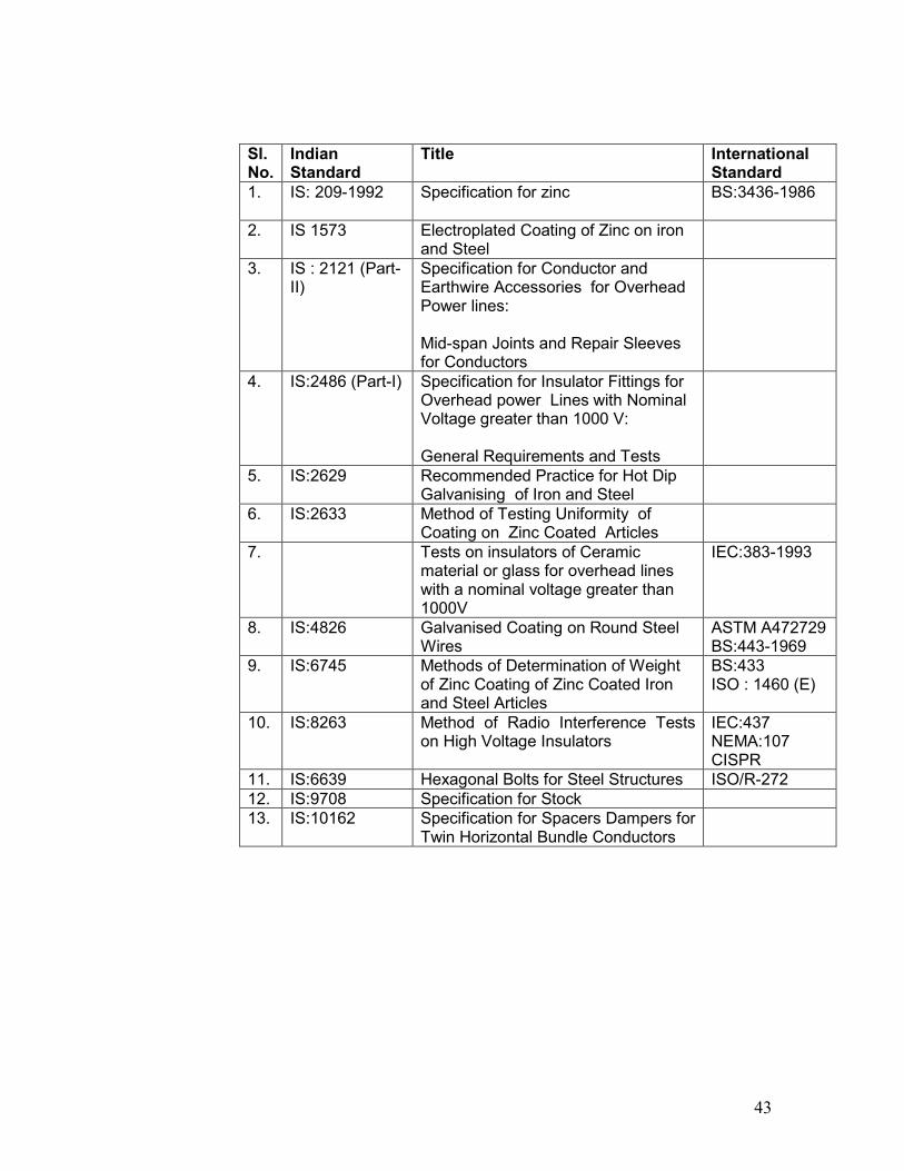
43
Sl. No.
Indian Standard
Title International Standard
1. IS: 209-1992 Specification for zinc BS:3436-1986
2. IS 1573 Electroplated Coating of Zinc on iron and Steel
3. IS : 2121 (Part-II)
Specification for Conductor and Earthwire Accessories for Overhead Power lines: Mid-span Joints and Repair Sleeves for Conductors
4. IS:2486 (Part-I) Specification for Insulator Fittings for Overhead power Lines with Nominal Voltage greater than 1000 V: General Requirements and Tests
5. IS:2629 Recommended Practice for Hot Dip Galvanising of Iron and Steel
6. IS:2633 Method of Testing Uniformity of Coating on Zinc Coated Articles
7. Tests on insulators of Ceramic material or glass for overhead lines with a nominal voltage greater than 1000V
IEC:383-1993
8. IS:4826 Galvanised Coating on Round Steel Wires
ASTM A472729 BS:443-1969
9. IS:6745 Methods of Determination of Weight of Zinc Coating of Zinc Coated Iron and Steel Articles
BS:433 ISO : 1460 (E)
10. IS:8263 Method of Radio Interference Tests on High Voltage Insulators
IEC:437 NEMA:107 CISPR
11. IS:6639 Hexagonal Bolts for Steel Structures ISO/R-272 12. IS:9708 Specification for Stock 13. IS:10162 Specification for Spacers Dampers for
Twin Horizontal Bundle Conductors
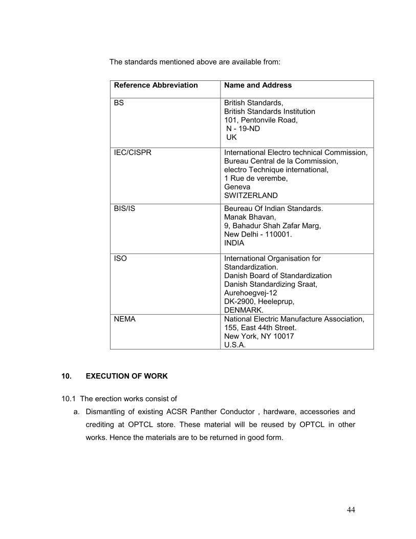
44
The standards mentioned above are available from:
Reference Abbreviation
Name and Address
BS British Standards, British Standards Institution 101, Pentonvile Road, N - 19-ND UK
IEC/CISPR International Electro technical Commission, Bureau Central de la Commission, electro Technique international, 1 Rue de verembe, Geneva SWITZERLAND
BIS/IS Beureau Of Indian Standards. Manak Bhavan, 9, Bahadur Shah Zafar Marg, New Delhi - 110001. INDIA
ISO International Organisation for Standardization. Danish Board of Standardization Danish Standardizing Sraat, Aurehoegvej-12 DK-2900, Heeleprup, DENMARK.
NEMA National Electric Manufacture Association, 155, East 44th Street. New York, NY 10017 U.S.A.
10. EXECUTION OF WORK
10.1 The erection works consist of
a. Dismantling of existing ACSR Panther Conductor , hardware, accessories and
crediting at OPTCL store. These material will be reused by OPTCL in other
works. Hence the materials are to be returned in good form.
45
c. Insurance of materials during storage-cum-erection.
d. Distribution of materials at erection site,
e. Stringing of conductor up to both ends of the lines, with the help of tensioner and
puller machine and if required, manually with the approval of the owner.
f. Guarantee of all the activities carried out from (a) to (e) and submission of FQP for
carrying out of all above activities.
g. Other items not specifically mentioned in this Specification and are required for the
successful erection and commissioning of the transmission lines, unless specifically
excluded in the Specification.
10.2 All works shall be carried out in accordance with the revised and latest provisions
under Indian Electricity Act and Rules made there under.
10.3 All the erection tools required during erection of lines shall be arranged by the
Contractor at his own cost. The Contractor shall also be responsible for any damage to
and / or loss of his erection tools.
10.4 In case of any deviation in quantities from the tendered quantity, payment will be
made with the approval from the corporate office of the owner.
10.5 It will be the Contractor’s sole responsibility to take the materials up to the location.
Any pathway, temporary road, temporary bridge required for the work, same will be
provided by the contractor at his cost. If, for any reasons the above is not feasible, the
contractor at his own cost shall have to arrange transportation by head loads.
11. STRINGING
The stringing work shall be carried with the help of tensioner and puller machines.
Wherever it is not possible to install the tensioner, it can be done manually with the
approval of site engineer of the owner. Stringing shall mean, the activities of paying,
jointing, tensioning, clamping with armor-rod, providing dampers and fixing the conductor
at tension hardware and jumpering etc.
11.1 Stringing of conductor shall be done up to gantry at both ends of the individual
lines.
b. Transportation, delivery of conductor, hardware, accessories etc. at erection site and
keeping in safe custody.
46
11.2 The stringing work should be planned in such a manner in consultation with the
Engineer in charge of the Owner that minimum shut down of power line crossings are
required. Revenue loss due to any undue shut down due to contractor’s irresponsibility
shall be recoverable from the contractor.
11.3 Before commencing of stringing work, Contractor shall obtain approval of sag
tension charts showing final sag and tension for various temperature and spans.
11.4 The Contractor shall be responsible and will take care of proper handling of
conductor drums. Sufficient numbers of aluminum snatch blocks shall be used for paying
out the Conductors. Necessary precautions shall be taken to avoid conductor rubbing on
the ground by providing adequate ground roller, rollers on supports. Additional rollers
shall also be provided to cross thorny hedges, tower footing and other obstructions to
avoid scratching of conductor. The conductor shall be made to sag correctly as per
stringing charts, before they are finally transferred to the hardware and clamps . No mid
span joint shall be made at less than 30 meters from the tower end and no mid span
joint shall be permitted in road and other important crossings spans. There shall not be
more than one joint in the same span of individual conductor. The sag shall be adjusted
to suit the sag indicated against actual temperature. The thermometer shall be provided
at the conductor point during the stringing work. Dynamo meters shall be used in
tensioning the conductors. All conductors shall be stressed to their load at the time of
stringing, as per approved stringing charts.
11.5 The minimum clearance between the lowest point of conductor and ground shall
not be less than as specified in the chart. All compression joints should be carefully
made and a record of initial and final lengths of the joints, jointly signed by contractor
and OPTCL representatives shall be maintained. Check for sag should also be made at
intervals when conductors are drawn up. Over stressing, causing damage to towers
must be avoided. Care should be exercised not to over tension the conductor.
To avoid contact with the ground or any object above ground level the conductors shall
be pulled by the controlled tension methods using neoprene lined double pulled wheel
type tension stringing equipments. The equipment shall be capable of maintaining
continuous tension of not less than of 3000 kg. per conductor.
47
11.6 When the conductor is on the stringing rollers before sagging-in, it shall be ensured
that the conductor is not damaged due to wind, vibration, vehicles or other causes.
Scaffolding should be used to cross the important road crossings for minimum
interruption to traffic.
11.7 The conductor shall be pulled up to desired sag and left in serial stringing sheaves
for at least one hour after which the sag shall be rechecked and adjusted, if necessary,
before clipping in and transferring the conductors from the serial stringing sheaves to the
suspension clamps.
11.8 The stringing rollers, when suspended on the transmission structure for supporting
conductors, shall be so adjusted that the conductor will be on the rollers at the same
height as the suspension clamp to which it is to be secured.
11.9 Armour rods and vibration dampers shall be fitted at each suspension and tension
tower before final clamping of conductor with Insulator strings. Vibration dampers are to
be fixed with clamping bolt and in correct vertical position in relation to conductor.
11.10 Compression type joints are to be used for jointing of conductors. Each part
connected with joints shall be perfectly cleaned & precautionary measures taken before
final compression. All the joints of conductors shall be made with the best workmanship
and shall be perfectly straight and having maximum possible strength.
11.11 Proper guys shall be provided to counter balance the paying out tension of
conductor at the tension locations, to avoid damage to towers and/or accident.
12. FIELD QUALITY PLAN (FQP)
Bidder shall invariably submit the FQP along with Technical Bid for erection of line
including all the activities such as dismantling, stringing etc. with detailed checklist to be
referred.
13. WASTAGE
13.1 The maximum permitted ceiling for wastages for conductor permitted is 0.5%
(maximum) which takes into account the additional length for sag & jumpers.
48
13.2 No wastage is allowed for any material except the percentage limit mentioned for
Conductor here in above in Clause No. 13.1
14. LOSSES
In the event of any material used for transmission line found broken or damaged or
received short during transit or failed during the erection / testing at site before
commissioning of line, the contractor shall replace the same free of cost.
15. COMMISSIONING
15.1 The contractor shall ensure that at the end of each sub-activity the surplus material
is immediately removed from the work-site to avoid loss and injury to the public.
15.2 The contractor has to make reconciliation of material account and to settle final bill
including signature in all relevant papers required for passing of final bill within three
months from the date of charging / commissioning of line.
16. DRAWINGS AND SPECIFICATIONS
16.1. Appendix-I: - Tower schedule showing individual span length,ruling span lengths &
existing ground clearance of 132KV Chandaka-Mancheswar circuit-II.
16.2. Appendix-II: - Tower schedule showing individual span length, ruling span
lengths, and existing ground clearance of 132KV Chandaka-Ranasingpur line.
16.3. Appendix-III: - Tower schedule showing individual span length, ruling span
lengths, and existing ground clearance of 132KV Chandaka-Nimapara line.
16.4 Appendix-IV: - Tower schedule showing individual span length, ruling span
lengths, and existing ground clearance of 132KV Tarkera-Chhend (D/C) line.
16.5 Appendix-V: - Spare list suitable for the offered HTLS conductor.
16.6 Appendix-VI: - List of rate contract holder firms of OPTCL.
49
ANNEXURE-A
1. Tests on Conductor
1.1 UTS Test on Stranded Conductor
Circles perpendicular to the axis of the conductor shall be marked at two places on a sample of conductor of minimum 5 m length between fixing arrangement suitably fixed by appropriate fittings on a tensile testing machine. The load shall be increased at a steady rate up to 50% of minimum specified UTS and held for one minute. The circles drawn shall not be distorted due to relative movement of strands. Thereafter the load shall be increased at steady rate to minimum UTS and held for one minute. The Conductor sample shall not fail during this period. The applied load shall then be increased until the failing load is reached and the value recorded.
1.2 D.C. Resistance Test on Stranded Conductor
On a conductor sample of minimum 5m length two contact-clamps shall be fixed with a predetermined bolt torque. The resistance shall be measured by a Kelvin double bridge or using micro ohm meter of suitable accuracy by placing the clamps initially zero metre and subsequently one metre apart. The test shall be repeated at least five times and the average value recorded. The value obtained shall be corrected to the value at 20ºC as per IS:398-(Part-IV)/(Part-V). The resistance corrected at 20deg C shall conform to the requirements of this Specification.
1.3 Coefficient of linear expansion for core/core strands
The temperature and elongation on a sample shall be continuously measured and recorded at interval of approximately 15 degree C from 15 degree C to maximum continuous operating temperature corresponding to rated current(800 A) by changing the temperature by suitable means. Coefficient of linear expansion shall be determined from the measured results.
1.4 Breaking load test on Aluminium Alloy & Core strands and D.C Resistance test on Aluminium Alloy wire
The above tests shall be carried out as per IEC: 888/889 and the results shall meet the requirements of the specification.
1.5 Wrap test on Core strand
The wrap test on steel strands shall be meet the requirements of IEC: 888. In case of aluminium clad core wire, the same shall be wraped around a mandel of diameter of five times that of the strand to form a helix of eight turns. The strand shall be unwrapped. No breakage of strand shall occurred.
50
1.6 Heat Resistance test on Aluminium Alloy wire
Breaking load test as per clause 1.4 above shall be carried out before and after heating the sample in uniform heat furnace at 280 degC (+5/-3 degC) temperature for one hour. The breaking strength of the wire after heating shall not be less than the 90% of the breaking strength before heating.
1.7 Chemical Analysis of Aluminium Alloy and Core
Samples taken from the Aluminium and core coils/strands shall be chemically/spectrographically analysed. The same shall be in conformity to the particulars guaranteed by the bidder so as to meet the requirements stated in this Specification.
1.8 Visual and Dimensional Check on Drums
The drums shall be visually and dimensionally checked to ensure that they conform to the approved drawings.
1.9 Visual Check for Joints, Scratches etc.
Conductor drums shall be rewound in the presence of the Employer. The Employer shall visually check for scratches, joints etc. and that the conductor generally conform to the requirements of this Specification. Ten percent (10%) drums from each lot shall be rewound in the presence of the Employer's representative.
1.10 Dimensional Check on Core Strands and Aluminium Alloy Strands
The individual strands shall be dimensionally checked to ensure that they conform to the requirement of this Specification.
1.11 Check for Lay-ratios of Various Layers
The lay-ratios of various layers shall be checked to ensure that they conform to
the guaranteed values furnished by the Contractor.
1.12 Procedure Qualification test on welded Aluminium Alloy strands.
Two Aluminium Alloy wire shall be welded as per the approved qualityplan and shall be subjected to tensile load. The breaking strength of the welded joint of the wire shall not be less than the guaranteed breaking strength of individual strands.
1.13 Chemical Analysis of Zinc
Samples taken from the zinc ingots shall be chemically/ spectrographically analyzed. The same shall be in conformity to the requirements stated in the Specification.
1.14 Galvanizing Test
The test procedure shall be as specified in IEC : 888. The material shall conform to the requirements of this Specification. The adherence of zinc shall be checked by wrapping around a mandrel four times the diameter of steel wire.

51
1.15 Torsion and Elongation Tests on Core Strands
The test procedures shall be as per clause No. 10.3 of IEC 888. In torsion test, the number of complete twists before fracture shall not be less than 18 on a length equal to 100 times the standard diameter of the strand. In case test sample length is less or more than 100 times the stranded diameter of the strand, the minimum number of twists will be proportioned to the length and if number comes in the fraction then it will be rounded off to next higher whole number. In elongation test, the elongation of the strand shall not be less than 1.5% for a gauge length of 250 mm.
1.16 Bending test on conductor core strand
A sample of conductor core strand measuring 30 cm in length shall be subject to bending with help of a vice. The viced length of wire should be 5 cm and radius of bend 4.8 mm. The bending should be first 90 degrees left and 90 degree right. After this operation the strand will be cut at the bending point. There should be no separation of core and aluminium at the bending point after this operation.
1.17 Aluminium conductivity test on aluminium clad strand
Resistivity test as per IEC-468 shall be conducted to confirm minimum conductivity as per specification requirement.
1.18 Minimum conductivity test on thermal resistant aluminium alloy strands
Resistivity test as per IEC-468/IEC 889 shall be conducted to confirm minimum conductivity as per specification requirement.
1.19 Stress-strain test at elevated temperature Stress-strain test as per IEC-1089 shall be conducted keeping conductor temperature at designed maximum temperature.
1.20 High Temperature endurance & creep test
A conductor sample of at least 20 m length shall be strung at tension equal to 25 % of conductor UTS. The conductor temperature shall be increased to designed maximum temperature in steps of 20 deg. C and thermal elongation of the conductor sample shall be measured & recorded at each step. Further, the temperature of the conductor shall be maintained at maximum continuous operating temperature (+10 Deg. C) for 1000 hours. The elongation/creep strain of the conductor during this period shall be measured and recorded at end of 1 hour, 10 hour, 100 hour and subsequently every 100 hour upto 1000 hours time period. After completion of the above, the conductor sample shall be subjected to UTS test as mentioned above at clause 1.1 of Annexure-A. The supplier shall furnish details of creep characteristic in respect of the conducted based on laboratory test and other laboratory investigations/
52
experimental conducted on similar type of conductor and shall indicate creep strain values corresponding to 1 month, 6 month, 1 year, 10 year & 20 year creep at everyday tension & continuous designed temperature.
1.21 Axial Impact Test
The conductor sample shall be suspended vertically and load applied by dropping a 650 Kg from an elevation of 4 meters above the sample. The impact velocity shall be not be less than 8 m/sec. with an initial pre-tension of 1% of the RTS ( Rated tensile strength). The curve for load vs time shall be recorded and recorded load of failure for core shall not be less than UTS of core.
1.22 Crush Strength Test
A section of conductor is to be crushed between two six inch steel platens. Load shall be held at 350 Kgs for 1 minute and then released. All the strands shall be subsequently disassembled and tensile tested. All the strands shall exhibit full strength retention
1.23 Torsional Ductility Test
After removing the outer layer aluminium/ aluminium alloy strands, the conductor shall be loaded to 25% of UTS and than loaded in increasing steps of +/-180 deg, the core shall withstand atleast 16 such rotation.
1.24 Sheaves Test (if required) The conductor sample of minimum length of 35 meter shall be tensioned at 22 % of the UTS and shall be passed through pulleys having diameter of 32 times that of the conductor with angle of 20 deg. between the pulleys. The conductor shall be passed over the pulleys 36 times a speed of 2 m/sec. After this test UTS test on the conductor shall be carried out.
53
ANNEXURE - B
1.0 Tests on Hardware Fittings
1.1 Magnetic Power Loss Test for Suspension Assembly
Two hollow aluminium tubes of 22 mm diameter for the conductor. An alternating current over the range of 600 to 960 amps shall be passed through each tube. The reading of the wattmeter with and without suspension assemblies alongwith line side yoke plate, clevis eye shall be recorded. Not less than three suspension assemblies shall be tested. The average power loss for suspension assembly. shall be plotted for each value of current. The value of the loss corresponding to 800 amperes per phase shall be read off from the graph and the same shall not be more than the value guaranteed by the supplier.
1.2 Galvanising/Electroplating Test
The test shall be carried out as per Clause no. 5.9 of IS:2486-(Part-1) except that both uniformity of zinc coating and standard preecee test shall be carried out and the results obtained shall satisfy the requirements of this specification.
1.3 Mechanical Strength Test of Each Component
Each component shall be subjected to a load equal to the specified minimum ultimate tensile strength (UTS) which shall be increased at a steady rate to 67% of the minimum UTS specified. The load shall be held for five minutes and then removed. The component shall then again be loaded to 50% of UTS and the load shall be further increased at a steady rate till the specified UTS and held for one minute. No fracture should occur. The applied load shall then be increased until the failing load is reached and the value recorded.
1.4 Clamp Slip Strength Vs Torque Test for Suspension Clamp
The suspension assembly shall be vertically suspended by means of a flexible attachment. A suitable length of conductor shall be fixed in the clamp. The clamp slip strength at various tightening torques shall be obtained by gradually applying the load at one end of the conductor. The Clamp slip strength vs torque curve shall be drawn. The above procedure is applicable only for free centre type suspension clamp. For AG suspension clamp only clamp slip strength after assembly shall be found out. The clamp slip strength at the recommended tightening torque shall be more than 07 kN but less than 14 kN.
1.5 Heating Cycle Test
Heating cycle test shall be performed in accordance with IS 2486 (Part-I) with following modifications:-
i) Temperature of conductor during each cycle: 40 deg. C above designed maximum operating temperature of the conductor.
54
ii) Number of cycle: 100
Slip strength test shall also be carried out after heating cycle test.
1.8 Shore Hardness Test for Elastomer Cushion for AG Suspension Assembly
The shore hardness at various points on the surface of the elastomer cushion shall be measured by a shore hardness meter and the shore hardness number shall be between 65 to 80.
1.9 Proof Load Test
Each component shall be subjected to a load equal to 50% of the specified minimum ultimate tensile strength which shall be increased at a steady rate to 67% of the UTS specified. The load shall be held for one minute and then removed. After removal of the load the component shall not show any visual deformation.
1.10 Tests for Forging Casting and Fabricated Hardware
The chemical analysis, hardness test, grain size, inclusion rating and magnetic particle inspection for forging, castings and chemical analysis and proof load test for fabricated hardware shall be as per the iniiternationally recognised procedures for these tests. The sampling will be based on heat number and heat treatment batch. The details regarding test will be as in the Quality Assurance programme.
2.0 Tests on Accessories for Conductor
2.1 Mid Span Compression Joint for Conductor.
(a) Slip Strength Test
The fitting compressed on conductor shall not be less than one metre in length. The test shall be carried out as per IS:2121 (Part-ii)-1981 clause 6-4 except that the load shall be steadily increased to 95% of minimum ultimate tensile strength of conductor/earthwire and retained for one minute at this load. There shall be no movement of the conductor/ earthwire relative to the fittings and no failure of the fit tings during this one minute period.
2.2 Connector for Conductor
Axial Tensile Load Test for Welded Portion
The sleeve portion of the T-Connector shall be compressed on conductor. The compressed portion shall be held rigidly on some fixtures and axial load shall be applied along with the jumper terminal The load shall be increased gradually till breaking of welded joint occurs. The breaking load should be above 30 kN.

55
Clamp Slip and Fatigue Tests
(i) Test Set Up
The clamp slip and fatigue tests shall be conducted on a laboratory set up with a minimum effective span length of 30 m. The conductor shall be tensioned at tension corresponding to 0 deg & no wind condition and ruling span 400 from sag –tension calculation and shall not be equipped with protective armour rods at any point. Constant tension shall be maintained within the span by means of lever arm arrangement. After the conductor has been tensioned, clamps shall be installed to support the conductor at both ends and thus influence of connecting hardware fittings are eliminated from the free span. The clamps shall not be used for holding the tension on the conductor. There shall be no loose parts, such as suspension clamps, U bolts on the test span supported between clamps mentioned above. The span shall be equipped with vibration inducing equipment suitable for producing steady standing vibration. The inducing equipment shall have facilities for stepless speed control as well as stepless amplitude arrangement. Equipment shall be available for measuring the frequency, cumulative number of cycles and amplitude of vibration at any point along the span.
(ii) Clamp Slip test
The vibration damper shall be installed on the test span. The damper clamp, after lightning with the manufacturer’s specified tightening torque, when subjected to a longitudinal pull of 2.5 kN parallel to the axis of conductor for a minimum duration of one minute shall not slip i.e. the permanent displacement between conductor and clamp measured after removal of the load shall not exceed 1.0 mm. The load shall be further increased till the clamp starts slipping. The load at which the clamp slips shall not be more than 5 kN.
3.0 Tests on All components (As applicable)
3.1 Chemical Analysis of Zinc used for Galvanizing
Samples taken from the zinc ingot shall be chemically analysed as per IS-209-1979. The purity of zinc shall not be less than 99.95%.
3.2 Tests for Forgings
The chemical analysis hardness tests and magnetic particle inspection for forgings, will be as per the internationally recognized procedures for these tests. The, sampling will be based on heat number and heat treatment batch. The details regarding test will be as discussed and mutually agreed to by the Contractor and Owner in Quality Assurance Programme.
3.3 Tests on Castings
The chemical analysis, mechanical and metallographic tests and magnetic particle inspection for castings will be as per the internationally recognised procedures for these tests. The samplings will be based on
56
heat number and heat treatment batch. The details regarding test will be as discussed and mutually agreed to by the Contractor and Owner in Quality Assurance Programme.
Acceptance Tests ANNEXURE-C
1 Mid Span Compression Joint for Conductor
(a) Hardness Test
The Brinnel hardness at various points on the steel sleeve of conductor core and tension clamp shall be measured.
2. Connector for Conductor
(a) Axial Tensile Load Test for Welded Portion
Same as clause 2.2 of Annexure - B .
3. Vibration Damper for Conductor
(a)Verification of Resonance Frequencies
The damper shall be mounted on a shaker table and vibrate at damper clamp displacement of +/-0.5 mm to determine the resonance frequencies. The resonance shall be visually identified as the frequency at which damper mass vibrates with maximum displacement on itself. The resonance frequency thus identified shall be compared with the guaranteed value. A tolerance of ± 1 Hz at a frequency lower than 15 Hz and ± 2 Hz at a frequency higher than 15 Hz only shall be allowed.
(b) Clamp Slip Test
(c) Clamp Bolt Torque Test
The clamp shall be attached to a section of the conductor/earthwire. A torque of 150 percent of the manufacturer’s specified torque shall be applied to the bolt. There shall be no failure of component parts.
(d) Strength of the Messenger Cable
The messenger cable shall be fixed in a suitable tensile testing machine and the tensile load shall be gradually applied until yield point is reached. Alternatively, each strand of messenger cable may be fixed in a suitable tensile testing machine and the tensile load shall be gradually applied until yield point is reached. In such a case, the 95% of yield strength of each wire shall be added to get the total strength of the cable. The load shall be not less than the value guaranteed by the Contractor
(e) Mass Pull off Test
Each mass shall be pulled off in turn by fixing the mass in one jaw and the clamp in the other of a suitable tensile testing machine. The longitudinal pull shall be applied gradually until the mass
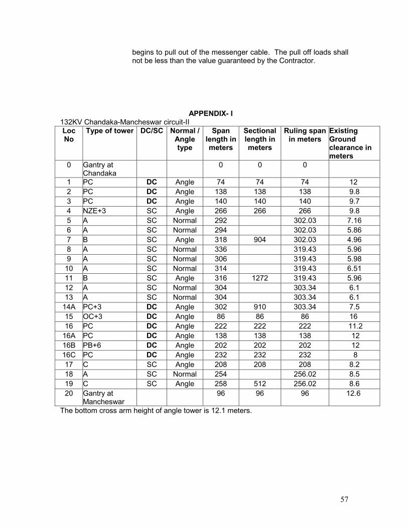
57
begins to pull out of the messenger cable. The pull off loads shall not be less than the value guaranteed by the Contractor.
APPENDIX- I 132KV Chandaka-Mancheswar circuit-II Loc No
Type of tower DC/SC Normal / Angle type
Span length in meters
Sectional length in meters
Ruling span in meters
Existing Ground clearance in meters
0 Gantry at Chandaka
0 0 0
1 PC DC Angle 74 74 74 12 2 PC DC Angle 138 138 138 9.8 3 PC DC Angle 140 140 140 9.7 4 NZE+3 SC Angle 266 266 266 9.8 5 A SC Normal 292 302.03 7.16 6 A SC Normal 294 302.03 5.86 7 B SC Angle 318 904 302.03 4.96 8 A SC Normal 336 319.43 5.96 9 A SC Normal 306 319.43 5.98
10 A SC Normal 314 319.43 6.51 11 B SC Angle 316 1272 319.43 5.96 12 A SC Normal 304 303.34 6.1 13 A SC Normal 304 303.34 6.1
14A PC+3 DC Angle 302 910 303.34 7.5 15 OC+3 DC Angle 86 86 86 16 16 PC DC Angle 222 222 222 11.2
16A PC DC Angle 138 138 138 12 16B PB+6 DC Angle 202 202 202 12 16C PC DC Angle 232 232 232 8 17 C SC Angle 208 208 208 8.2 18 A SC Normal 254 256.02 8.5 19 C SC Angle 258 512 256.02 8.6 20 Gantry at
Mancheswar 96 96 96 12.6
The bottom cross arm height of angle tower is 12.1 meters.
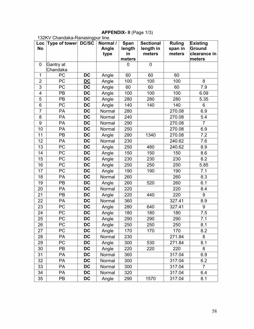
58
APPENDIX- II (Page 1/3) 132KV Chandaka-Ranasingpur line. Loc No
Type of tower DC/SC Normal / Angle type
Span length in
meters
Sectional length in meters
Ruling span in meters
Existing Ground clearance in meters
0 Gantry at Chandaka
0 0
1 PC DC Angle 60 60 60 2 PC DC Angle 100 100 100 8 3 PC DC Angle 60 60 60 7.9 4 PB DC Angle 100 100 100 6.09 5 PB DC Angle 280 280 280 5.35 6 PC DC Angle 140 140 140 6 7 PA DC Normal 280 270.08 6.9 8 PA DC Normal 240 270.08 5.4 9 PA DC Normal 290 270.08 7
10 PA DC Normal 250 270.08 6.9 11 PB DC Angle 280 1340 270.08 7.2 12 PA DC Normal 230 240.62 7.6 13 PC DC Angle 250 480 240.62 8.9 14 PC DC Angle 150 150 150 8.6 15 PC DC Angle 230 230 230 8.2 16 PC DC Angle 250 250 250 5.85 17 PC DC Angle 190 190 190 7.1 18 PA DC Normal 260 260 8.3 19 PB DC Angle 260 520 260 6.1 20 PA DC Normal 220 220 8.4 21 PB DC Angle 220 440 220 9 22 PA DC Normal 360 327.41 8.9 23 PC DC Angle 280 640 327.41 9 24 PC DC Angle 180 180 180 7.5 25 PC DC Angle 290 290 290 7.1 26 PC DC Angle 250 250 250 8.1 27 PC DC Angle 170 170 170 8.2 28 PA DC Normal 230 271.84 8 29 PC DC Angle 300 530 271.84 8.1 30 PB DC Angle 220 220 220 8 31 PA DC Normal 360 317.04 6.9 32 PA DC Normal 300 317.04 6.2 33 PA DC Normal 300 317.04 7 34 PA DC Normal 320 317.04 6.4 35 PB DC Angle 290 1570 317.04 8.1

59
APPENDIX- II (Continued)(Page 2/3) 132KV Chandaka-Ranasingpur line. Loc No
Type of tower DC/SC Normal / Angle type
Span length in
meters
Sectional length in meters
Ruling span in meters
Existing Ground clearance in meters
36 PA l DC
Normal 250 272.21 7.9
37 PC DC Angle 290 540 272.21 8 38 PC DC Angle 150 150 150 7.9 39 PC DC Angle 200 200 200 8 40 PA DC Normal 270 240.2 7.2 41 PB DC Angle 190 460 240.2 7 42 PC DC Angle 160 160 160 8.1 43 PB DC Angle 60 60 60 7.8 44 PB DC Angle 290 290 290 7.1 45 PA DC Normal 310 338.22 8.3 46 PA+3 DC Normal 350 338.22 8.1 47 PB DC Angle 350 1010 338.22 8 48 PA DC Normal 300 313.76 7.9 49 PA DC Normal 320 313.76 8.1 50 PB DC Angle 320 940 313.76 8.2 51 PA+3 DC Normal 330 340.41 7.9 52 PC DC Angle 350 680 340.41 8.55 53 PB DC Angle 200 200 200 8.05 54 PA DC Normal 280 275.4 8 55 PA DC Normal 280 275.4 7.9 56 PA DC Normal 280 275.4 7.5 57 PC DC Angle 260 1100 275.4 8.3 58 PA DC Normal 300 290.51 7.1 59 PB DC Angle 280 580 290.51 7.5 60 PA DC Normal 310 312.84 7.4 61 PA DC Normal 330 312.84 7.7 62 PA DC Normal 320 312.84 7.2 63 PA DC Normal 290 312.84 8 64 PB DC Angle 310 1560 312.84 7.1 65 PA DC Normal 310 322.38 7.15 66 PA DC Normal 310 322.38 6.9 67 PA+3 DC Normal 340 322.38 7 68 PA DC Normal 360 322.38 6.9 69 PA DC Normal 300 322.38 7.2 70 PB DC Angle 300 1920 322.38 8
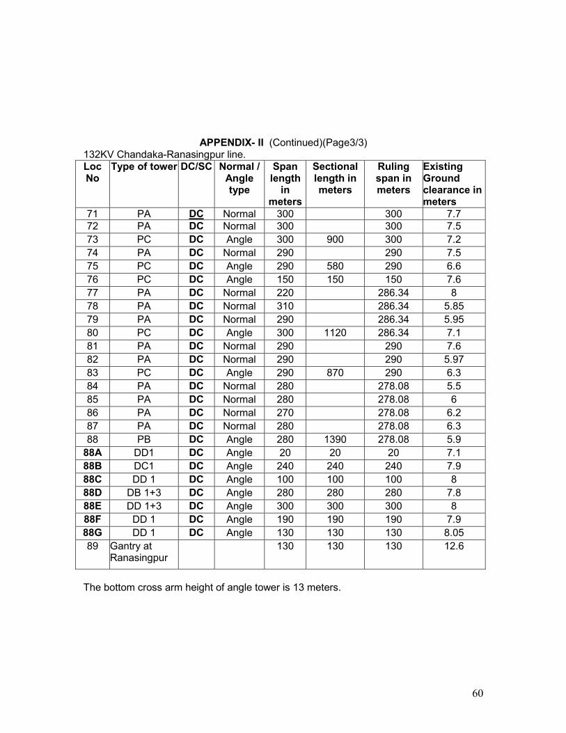
60
APPENDIX- II (Continued)(Page3/3) 132KV Chandaka-Ranasingpur line. Loc No
Type of tower DC/SC Normal / Angle type
Span length in
meters
Sectional length in meters
Ruling span in meters
Existing Ground clearance in meters
71 PA DC Normal 300 300 7.7 72 PA DC Normal 300 300 7.5 73 PC DC Angle 300 900 300 7.2 74 PA DC Normal 290 290 7.5 75 PC DC Angle 290 580 290 6.6 76 PC DC Angle 150 150 150 7.6 77 PA DC Normal 220 286.34 8 78 PA DC Normal 310 286.34 5.85 79 PA DC Normal 290 286.34 5.95 80 PC DC Angle 300 1120 286.34 7.1 81 PA DC Normal 290 290 7.6 82 PA DC Normal 290 290 5.97 83 PC DC Angle 290 870 290 6.3 84 PA DC Normal 280 278.08 5.5 85 PA DC Normal 280 278.08 6 86 PA DC Normal 270 278.08 6.2 87 PA DC Normal 280 278.08 6.3 88 PB DC Angle 280 1390 278.08 5.9 88A DD1 DC Angle 20 20 20 7.1 88B DC1 DC Angle 240 240 240 7.9 88C DD 1 DC Angle 100 100 100 8 88D DB 1+3 DC Angle 280 280 280 7.8 88E DD 1+3 DC Angle 300 300 300 8 88F DD 1 DC Angle 190 190 190 7.9 88G DD 1 DC Angle 130 130 130 8.05 89 Gantry at
Ranasingpur 130 130 130 12.6
The bottom cross arm height of angle tower is 13 meters.
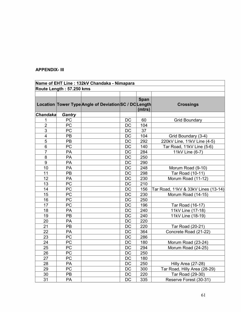
61
APPENDIX- III
Name of EHT Line : 132kV Chandaka - Nimapara Route Length : 57.250 kms
Location Tower Type Angle of Deviation SC / DC Span Length (mtrs)
Crossings
Chandaka Gantry 1 PC DC 60 Grid Boundary 2 PC DC 104 3 PC DC 37 4 PB DC 104 Grid Boundary (3-4) 5 PB DC 292 220kV Line, 11kV Line (4-5) 6 PC DC 140 Tar Road, 11kV Line (5-6) 7 PA DC 284 11kV Line (6-7) 8 PA DC 250 9 PA DC 290 10 PA DC 248 Morum Road (9-10) 11 PB DC 298 Tar Road (10-11) 12 PA DC 230 Morum Road (11-12) 13 PC DC 210 14 PC DC 156 Tar Road, 11kV & 33kV Lines (13-14) 15 PC DC 230 Morum Road (14-15) 16 PC DC 250 17 PC DC 196 Tar Road (16-17) 18 PA DC 240 11kV Line (17-18) 19 PB DC 240 11kV Line (18-19) 20 PA DC 220 21 PB DC 220 Tar Road (20-21) 22 PA DC 364 Concrete Road (21-22) 23 PC DC 286 24 PC DC 180 Morum Road (23-24) 25 PC DC 294 Morum Road (24-25) 26 PC DC 250 27 PC DC 180 28 PA DC 250 Hilly Area (27-28) 29 PC DC 300 Tar Road, Hilly Area (28-29) 30 PB DC 220 Tar Road (29-30) 31 PA DC 335 Reserve Forest (30-31)
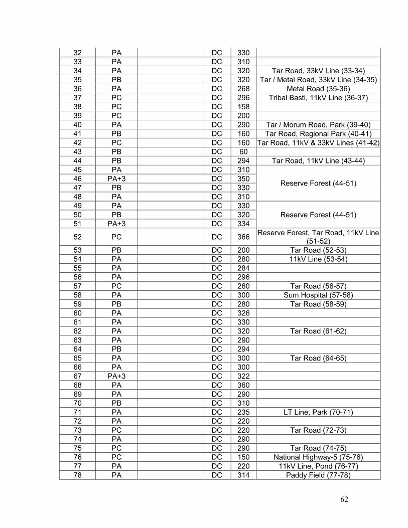
62
32 PA DC 330 33 PA DC 310 34 PA DC 320 Tar Road, 33kV Line (33-34) 35 PB DC 320 Tar / Metal Road, 33kV Line (34-35) 36 PA DC 268 Metal Road (35-36) 37 PC DC 296 Tribal Basti, 11kV Line (36-37) 38 PC DC 158 39 PC DC 200 40 PA DC 290 Tar / Morum Road, Park (39-40) 41 PB DC 160 Tar Road, Regional Park (40-41) 42 PC DC 160 Tar Road, 11kV & 33kV Lines (41-42) 43 PB DC 60 44 PB DC 294 Tar Road, 11kV Line (43-44) 45 PA DC 310
Reserve Forest (44-51) 46 PA+3 DC 350 47 PB DC 330 48 PA DC 310 49 PA DC 330
Reserve Forest (44-51) 50 PB DC 320 51 PA+3 DC 334
52 PC DC 366 Reserve Forest, Tar Road, 11kV Line (51-52)
53 PB DC 200 Tar Road (52-53) 54 PA DC 280 11kV Line (53-54) 55 PA DC 284 56 PA DC 296 57 PC DC 260 Tar Road (56-57) 58 PA DC 300 Sum Hospital (57-58) 59 PB DC 280 Tar Road (58-59) 60 PA DC 326 61 PA DC 330 62 PA DC 320 Tar Road (61-62) 63 PA DC 290 64 PB DC 294 65 PA DC 300 Tar Road (64-65) 66 PA DC 300 67 PA+3 DC 322 68 PA DC 360 69 PA DC 290 70 PB DC 310 71 PA DC 235 LT Line, Park (70-71) 72 PA DC 220 73 PC DC 220 Tar Road (72-73) 74 PA DC 290 75 PC DC 290 Tar Road (74-75) 76 PC DC 150 National Highway-5 (75-76) 77 PA DC 220 11kV Line, Pond (76-77) 78 PA DC 314 Paddy Field (77-78)
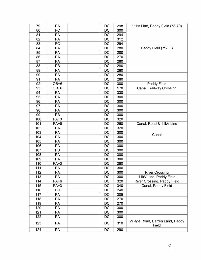
63
79 PA DC 298 11kV Line, Paddy Field (78-79) 80 PC DC 300
Paddy Field (79-88)
81 PA DC 294 82 PA DC 312 83 PC DC 294 84 PA DC 280 85 PA DC 280 86 PA DC 270 87 PA DC 280 88 PB DC 280 89 PA DC 280 90 PA DC 280 91 PA DC 280 92 OB+6 DC 300 Paddy Field 93 OB+6 DC 170 Canal, Railway Crossing 94 PA DC 330 95 PA DC 300 96 PA DC 300 97 PA DC 300 98 PA DC 300 99 PB DC 300
100 PA+3 DC 320 101 PA+6 DC 260 Canal, Road & 11kV Line 102 PA DC 320 103 PA DC 300
Canal 104 PA DC 300 105 PA DC 300 106 PA DC 300 107 PB DC 300 108 PA DC 300 109 PA DC 300 110 PA+3 DC 280 111 PA DC 300 112 PA DC 300 River Crossing 113 PA DC 300 11kV Line, Paddy Field 114 PA+6 DC 320 River Crossing, Paddy Field 115 PA+3 DC 340 Canal, Paddy Field 116 PC DC 240 117 PA DC 305 118 PA DC 270 119 PA DC 270 120 PA DC 300 121 PA DC 300 122 PA DC 300
123 PA DC 310 Village Road, Barren Land, Paddy Field
124 PA DC 290
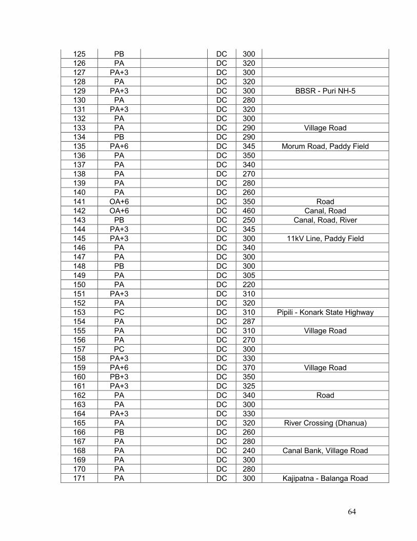
64
125 PB DC 300 126 PA DC 320 127 PA+3 DC 300 128 PA DC 320 129 PA+3 DC 300 BBSR - Puri NH-5 130 PA DC 280 131 PA+3 DC 320 132 PA DC 300 133 PA DC 290 Village Road 134 PB DC 290 135 PA+6 DC 345 Morum Road, Paddy Field 136 PA DC 350 137 PA DC 340 138 PA DC 270 139 PA DC 280 140 PA DC 260 141 OA+6 DC 350 Road 142 OA+6 DC 460 Canal, Road 143 PB DC 250 Canal, Road, River 144 PA+3 DC 345 145 PA+3 DC 300 11kV Line, Paddy Field 146 PA DC 340 147 PA DC 300 148 PB DC 300 149 PA DC 305 150 PA DC 220 151 PA+3 DC 310 152 PA DC 320 153 PC DC 310 Pipili - Konark State Highway 154 PA DC 287 155 PA DC 310 Village Road 156 PA DC 270 157 PC DC 300 158 PA+3 DC 330 159 PA+6 DC 370 Village Road 160 PB+3 DC 350 161 PA+3 DC 325 162 PA DC 340 Road 163 PA DC 300 164 PA+3 DC 330 165 PA DC 320 River Crossing (Dhanua) 166 PB DC 260 167 PA DC 280 168 PA DC 240 Canal Bank, Village Road 169 PA DC 300 170 PA DC 280 171 PA DC 300 Kajipatna - Balanga Road
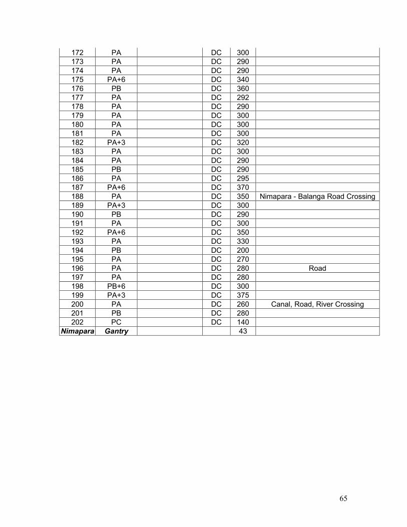
65
172 PA DC 300 173 PA DC 290 174 PA DC 290 175 PA+6 DC 340 176 PB DC 360 177 PA DC 292 178 PA DC 290 179 PA DC 300 180 PA DC 300 181 PA DC 300 182 PA+3 DC 320 183 PA DC 300 184 PA DC 290 185 PB DC 290 186 PA DC 295 187 PA+6 DC 370 188 PA DC 350 Nimapara - Balanga Road Crossing 189 PA+3 DC 300 190 PB DC 290 191 PA DC 300 192 PA+6 DC 350 193 PA DC 330 194 PB DC 200 195 PA DC 270 196 PA DC 280 Road 197 PA DC 280 198 PB+6 DC 300 199 PA+3 DC 375 200 PA DC 260 Canal, Road, River Crossing 201 PB DC 280 202 PC DC 140
Nimapara Gantry 43
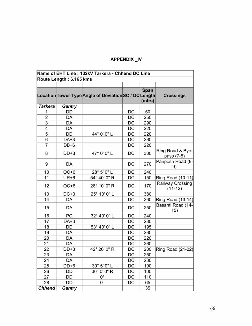
66
APPENDIX _IV
Name of EHT Line : 132kV Tarkera - Chhend DC Line Route Length : 6.165 kms
Location Tower Type Angle of Deviation SC / DC Span Length (mtrs)
Crossings
Tarkera Gantry 1 DD DC 50 2 DA DC 250 3 DA DC 290 4 DA DC 220 5 DD 44° 0' 0" L DC 220 6 DA+3 DC 260 7 DB+6 DC 220
8 DD+3 47° 0' 0" L DC 300 Ring Road & Bye-pass (7-8)
9 DA DC 270 Panposh Road (8-9)
10 OC+6 28° 5' 0" L DC 240 11 UR+6 54° 40' 0" R DC 150 Ring Road (10-11)
12 OC+6 28° 10' 0" R DC 170 Railway Crossing (11-12)
13 DC+3 25° 10' 0" L DC 380 14 DA DC 260 Ring Road (13-14)
15 DA DC 250 Basanti Road (14-15)
16 PC 32° 40' 0" L DC 240 17 DA+3 DC 280 18 DD 53° 40' 0" L DC 195 19 DA DC 260 20 DA DC 220 21 DA DC 260 22 DD+3 42° 20' 0" R DC 200 Ring Road (21-22) 23 DA DC 250 24 DA DC 230 25 DD+6 30° 5' 0" L DC 190 26 DD 30° 0' 0" R DC 100 27 DD 0° DC 110 28 DD 0° DC 65
Chhend Gantry 35
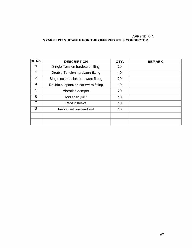
67
APPENDIX- V
SPARE LIST SUITABLE FOR THE OFFERED HTLS CONDUCTOR.
Sl. No. DESCRIPTION QTY. REMARK 1 Single Tension hardware fitting 20
2 Double Tension hardware fitting 10
3 Single suspension hardware fitting 20
4 Double suspension hardware fitting 10
5 Vibration damper 20
6 Mid span joint 10
7 Repair sleeve 10
8 Performed armored rod 10
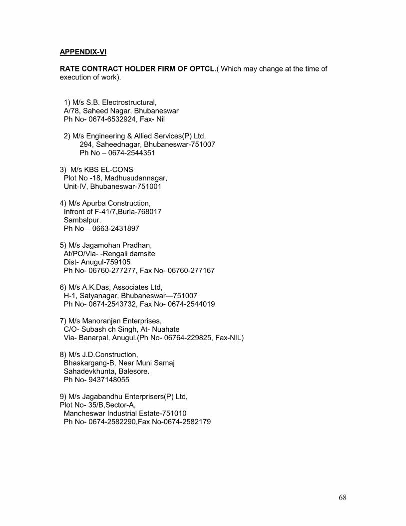
68
APPENDIX-VI RATE CONTRACT HOLDER FIRM OF OPTCL.( Which may change at the time of execution of work). 1) M/s S.B. Electrostructural, A/78, Saheed Nagar, Bhubaneswar Ph No- 0674-6532924, Fax- Nil 2) M/s Engineering & Allied Services(P) Ltd, 294, Saheednagar, Bhubaneswar-751007 Ph No – 0674-2544351
3) M/s KBS EL-CONS Plot No -18, Madhusudannagar, Unit-IV, Bhubaneswar-751001
4) M/s Apurba Construction, Infront of F-41/7,Burla-768017 Sambalpur. Ph No – 0663-2431897
5) M/s Jagamohan Pradhan, At/PO/Via- -Rengali damsite Dist- Anugul-759105 Ph No- 06760-277277, Fax No- 06760-277167
6) M/s A.K.Das, Associates Ltd, H-1, Satyanagar, Bhubaneswar—751007 Ph No- 0674-2543732, Fax No- 0674-2544019
7) M/s Manoranjan Enterprises, C/O- Subash ch Singh, At- Nuahate Via- Banarpal, Anugul.(Ph No- 06764-229825, Fax-NIL)
8) M/s J.D.Construction, Bhaskargang-B, Near Muni Samaj Sahadevkhunta, Balesore. Ph No- 9437148055
9) M/s Jagabandhu Enterprisers(P) Ltd, Plot No- 35/B,Sector-A, Mancheswar Industrial Estate-751010 Ph No- 0674-2582290,Fax No-0674-2582179
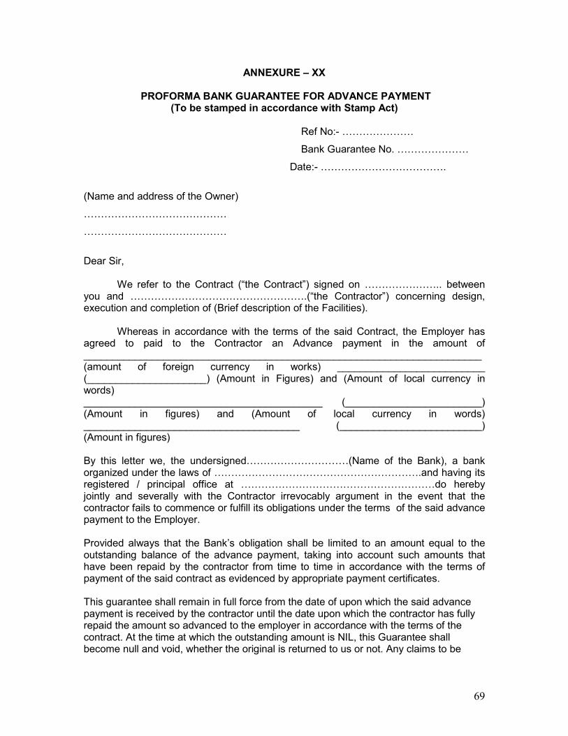
69
ANNEXURE – XX
PROFORMA BANK GUARANTEE FOR ADVANCE PAYMENT (To be stamped in accordance with Stamp Act)
Ref No:- …………………
Bank Guarantee No. …………………
Date:- ……………………………….
(Name and address of the Owner)
……………………………………
……………………………………
Dear Sir,
We refer to the Contract (“the Contract”) signed on ………………….. between you and …………………………………………….(“the Contractor”) concerning design, execution and completion of (Brief description of the Facilities).
Whereas in accordance with the terms of the said Contract, the Employer has agreed to paid to the Contractor an Advance payment in the amount of ______________________________________________________________________ (amount of foreign currency in works) __________________________ (_____________________) (Amount in Figures) and (Amount of local currency in words) __________________________________________ (________________________) (Amount in figures) and (Amount of local currency in words) ______________________________________ (_________________________) (Amount in figures) By this letter we, the undersigned…………………………(Name of the Bank), a bank organized under the laws of …………………………………………………….and having its registered / principal office at …………………………………………………do hereby jointly and severally with the Contractor irrevocably argument in the event that the contractor fails to commence or fulfill its obligations under the terms of the said advance payment to the Employer. Provided always that the Bank’s obligation shall be limited to an amount equal to the outstanding balance of the advance payment, taking into account such amounts that have been repaid by the contractor from time to time in accordance with the terms of payment of the said contract as evidenced by appropriate payment certificates. This guarantee shall remain in full force from the date of upon which the said advance payment is received by the contractor until the date upon which the contractor has fully repaid the amount so advanced to the employer in accordance with the terms of the contract. At the time at which the outstanding amount is NIL, this Guarantee shall become null and void, whether the original is returned to us or not. Any claims to be
70
made under this Guarantee must be received by the Bank during its period of validity i.e. on or before ___________*(year, month, date). Yours truly, Name of the Bank Authorized signature Signature of witness________ Name_________ Address________________
• The date shall be three (3) months after the date of operational acceptance by the Employer.
Note: 1. The non-judicial stamp papers of appropriate value shall be purchased in the
name of the Bank who issues the “Bank Guarantee”. 2. Performance security is to be provided by the successful bidder in the form of a
bank guarantee, which should be issued either: (a) by a reputed bank located in the country of the Employer and acceptable to the
Employer or (b) By a foreign bank confirmed by either its correspondent bank located in the
country of the Employer which should be reputed and acceptable to the Employer, or a Public Sector Bank in the country of the Employer.
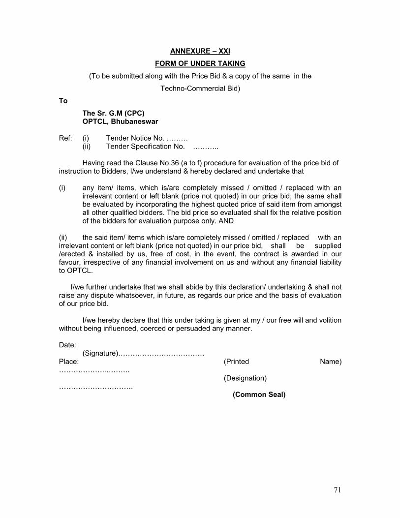
71
ANNEXURE – XXI
FORM OF UNDER TAKING
(To be submitted along with the Price Bid & a copy of the same in the
Techno-Commercial Bid)
To
The Sr. G.M (CPC) OPTCL, Bhubaneswar Ref: (i) Tender Notice No. ……… (ii) Tender Specification No. ……….. Having read the Clause No.36 (a to f) procedure for evaluation of the price bid of instruction to Bidders, I/we understand & hereby declared and undertake that (i) any item/ items, which is/are completely missed / omitted / replaced with an
irrelevant content or left blank (price not quoted) in our price bid, the same shall be evaluated by incorporating the highest quoted price of said item from amongst all other qualified bidders. The bid price so evaluated shall fix the relative position of the bidders for evaluation purpose only. AND
(ii) the said item/ items which is/are completely missed / omitted / replaced with an irrelevant content or left blank (price not quoted) in our price bid, shall be supplied /erected & installed by us, free of cost, in the event, the contract is awarded in our favour, irrespective of any financial involvement on us and without any financial liability to OPTCL.
I/we further undertake that we shall abide by this declaration/ undertaking & shall not
raise any dispute whatsoever, in future, as regards our price and the basis of evaluation of our price bid.
I/we hereby declare that this under taking is given at my / our free will and volition without being influenced, coerced or persuaded any manner. Date: (Signature)……………………………… Place: (Printed Name) ………………..………. (Designation) ………………………….
(Common Seal)