3. meshing the model - sharcnet: welcome · pdf file3. meshing the model when you click the...
TRANSCRIPT
MESHING THE MODEL
© 1998–2007 Fluent, Inc. All rights reserved. 3-1
3. MESHING THE MODEL
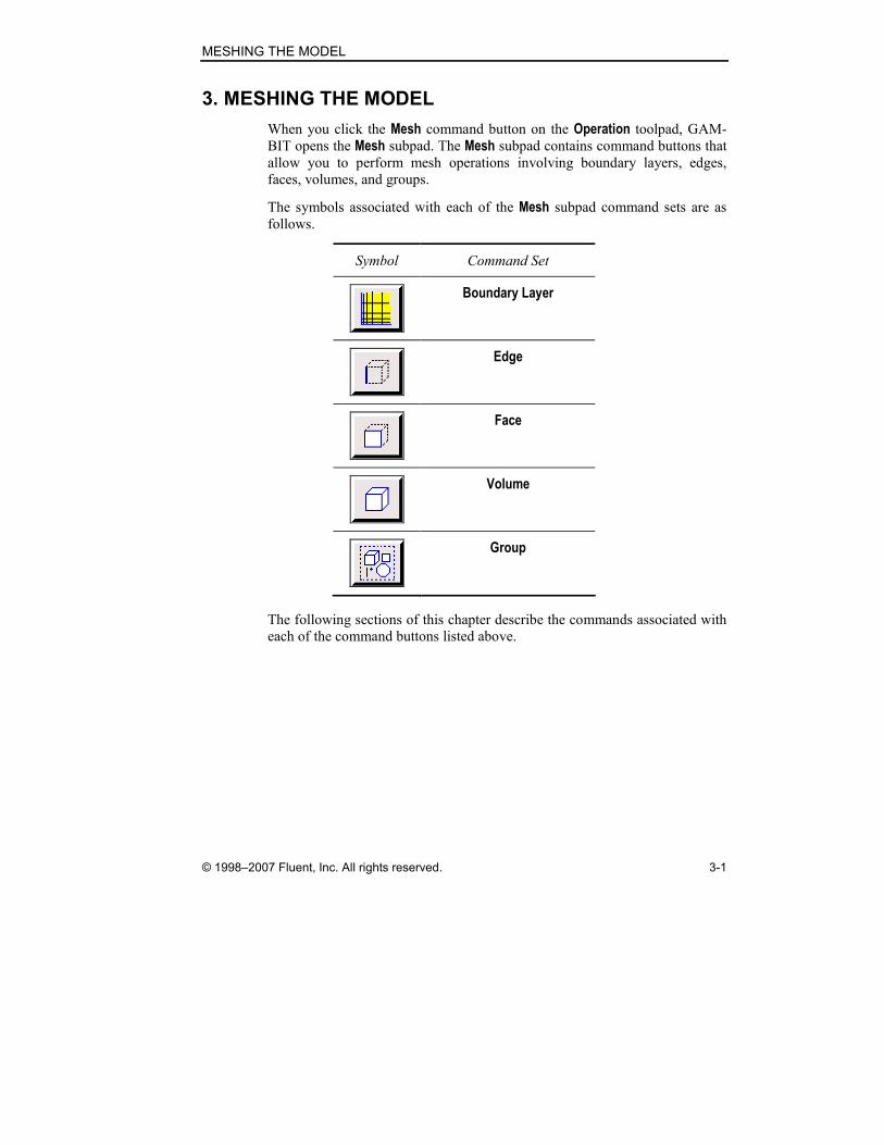
When you click the Mesh command button on the Operation toolpad, GAM-
BIT opens the Mesh subpad. The Mesh subpad contains command buttons that
allow you to perform mesh operations involving boundary layers, edges,
faces, volumes, and groups.
The symbols associated with each of the Mesh subpad command sets are as
follows.
Symbol Command Set
Boundary Layer
Edge
Face
Volume
Group
The following sections of this chapter describe the commands associated with
each of the command buttons listed above.
Boundary Layers MESHING THE MODEL
3-2 © 1998–2007 Fluent, Inc. All rights reserved.
3.1 Boundary Layers
3.1.1 Overview
Boundary layers define the spacing of mesh node rows in regions immediately
adjacent to edges and/or faces. They are used primarily to control mesh den-
sity and, thereby, to control the amount of information available from the
computational model in specific regions of interest.
As an example of a boundary layer application, consider a computational
model that includes a cylinder representing a pipe through which flows a vis-
cous fluid. Under normal circumstances, it is likely that the velocity gradients
are large in the region immediately adjacent to the pipe wall and small near
the center of the pipe. By attaching a boundary layer to the face that represents
the pipe wall, you can increase the mesh density near the wall and decrease
the density near the center of the cylinder, thereby obtaining sufficient infor-
mation to characterize the gradients in both regions while minimizing the total
number of mesh nodes in the model.
To define a boundary layer, you must specify the following information:
• Boundary-layer algorithm
• Height of the first row of mesh elements
• Growth factor—which specifies the height of each succeeding row of
elements
• Total number of rows—which defines the depth of the boundary layer
• Edge or face to which the boundary layer is attached
• Face or volume that defines the direction of the boundary layer
You can also specify the creation of a transition boundary layer—that is, a
boundary layer for which the mesh node pattern changes with each succeeding
layer. If you specify a transition boundary layer, you must also specify the
transition pattern and number of transition rows.

MESHING THE MODEL Boundary Layers
© 1998–2007 Fluent, Inc. All rights reserved. 3-3
3.1.2 Boundary Layer Commands
The following commands are available on the Mesh/Boundary Layer subpad.
Symbol Command Description
Create Boundary Layer Creates a boundary layer attached to
an edge or face
Modify Boundary Layer Modifies the definition of an existing
boundary layer
View 3D Boundary Layers Meshes and displays 3-D boundary
layer regions
Modify Label Modifies boundary layer labels
Summarize Boundary Layers Displays existing boundary layers in
the graphics window
Delete Boundary Layers Deletes boundary layers

Boundary Layers MESHING THE MODEL
3-4 © 1998–2007 Fluent, Inc. All rights reserved.
Create Boundary Layer
The Create Boundary Layer operation (blayer create and blayer
attach commands) defines the spacing of mesh nodes in the vicinity of an
edge or face. The operation requires the following specifications.
• Definition
• Transition pattern
• Attachment
The Definition specifications include the algorithm type and dimension
parameters that determine the shape of the boundary layer, as well as options
that govern the behavior of boundary layers in corner regions. The Transition pattern specifies the arrangement of mesh nodes in the boundary layer region.
The Attachment parameters include the entities to which the boundary layer is
attached and the entities that specify its direction.
Specifying the Definition
To define a boundary layer, you must specify the following parameters:
• Algorithm
• Dimensions
• Internal continuity option
• Corner shape option
The Algorithm specifies the method that GAMBIT uses to determine the gen-
eral shape of the boundary layer. The dimension parameters specify factors
such as the number of boundary layer rows and growth factor. The Internal continuity option specifies the behavior of the boundary layer in regions where it overlaps adjoining boundary layers. The Corner shape option determines the
shape of the mesh in regions surrounding Corner or Reversal vertices that con-nect edges to which boundary layers are attached.

MESHING THE MODEL Boundary Layers
© 1998–2007 Fluent, Inc. All rights reserved. 3-5
Specifying the Algorithm
The Algorithm specification determines the method that GAMBIT uses to
establish the heights of the elements in the first row of the boundary layer and
compute the heights of all succeeding rows. GAMBIT provides the following
algorithm types.
• Uniform—assigns a uniform height to all first-row elements and uses a
universal growth factor for succeeding rows
• Aspect ratio (first)—computes first-row element heights as a fixed per-
centage of the mesh element widths on the attachment entity and uses
a universal growth factor
• Aspect ratio (last)—assigns a uniform height to all first-row elements
and uses individual growth factors at each attachment-entity mesh
node to determine the size of succeeding rows
Figure 3-1, Figure 3-2, and Figure 3-3 illustrate the differences between the
Uniform, Aspect ratio (first), and Aspect ratio (last) algorithms for a 2-D boundary
layer attached to one edge of a square planar face. In each figure, the attach-
ment edge mesh includes five intervals and a grading ratio of 1.25, and the
boundary layer includes five rows.
Figure 3-1: Uniform boundary layer algorithm (2-D)

Boundary Layers MESHING THE MODEL
3-6 © 1998–2007 Fluent, Inc. All rights reserved.
Figure 3-2: Aspect ratio (first) boundary layer algorithm (2-D)
Figure 3-3: Aspect ratio (last) boundary layer algorithm (2-D)

MESHING THE MODEL Boundary Layers
© 1998–2007 Fluent, Inc. All rights reserved. 3-7
For the Uniform boundary layer (Figure 3-1), the first row exhibits a uniform
height across the span of the attachment edge, and the growth factor is
constant; therefore, each succeeding row of elements also exhibits a uniform
height. For the Aspect ratio (first) boundary layer (Figure 3-2), the first-row heights vary in proportion to the edge mesh interval lengths. Consequently,
the first row of the boundary layer grows thicker from left to right across the
edge, because the edge mesh interval lengths increase from left to right. For
the Aspect ratio (last) boundary layer (Figure 3-3), the first row exhibits a uni-form height across the span of the attachment edge, but the growth factor
varies in proportion to the edge mesh interval widths. Consequently, the suc-
ceeding rows grow thicker from left to right across the edge.
� NOTE: If the attachment edge shown in Figure 3-1, Figure 3-2, and Figure
3-3, above, were graded uniformly (Ratio = 1), all three Algorithm options would produce boundary layers of uniform height across the span of the edge.
If you attach a boundary layer to a face (rather than an edge), GAMBIT
applies the definition algorithm along the boundaries of the attachment face.
For example, Figure 3-4 shows an Aspect ratio (first) boundary layer attached to one face of a cube. In this case, the boundary edges of the attachment face
have been premeshed using five intervals and a grading ratio of 1.25.
Figure 3-4: Aspect ratio (first) boundary layer algorithm (3-D)

Boundary Layers MESHING THE MODEL
3-8 © 1998–2007 Fluent, Inc. All rights reserved.
When attaching a boundary layer to a face, care must be taken to ensure that
the boundary layer is not discontinuous at any vertices on the face boundary.
In Figure 3-4, above, the boundary edges of the attachment face are graded
such that the mesh interval widths on either side of any corner vertex are equal
to each other. As a result, the 3-D boundary layer is continuous at all four cor-
ners of the attachment face. In Figure 3-5, the face boundary edges are graded
such that edge mesh interval lengths differ on either side of three of the four
corner vertices (b, c, and d). Consequently, the boundary layer exhibits dis-
continuities at those vertices.
a
b
c
d
Figure 3-5: Effect of discontinuous grading at face boundary vertices
Specifying the Dimensions
To specify the dimensions of any boundary layer, you must input three
parameters that define its characteristics. The parameters to be specified vary
according to algorithm as follows.
Uniform Algorithm
The Uniform algorithm (see Figure 3-6) definition parameters are as follows.
• First row (a)
• Growth factor (b/a)
• Rows
MESHING THE MODEL Boundary Layers
© 1998–2007 Fluent, Inc. All rights reserved. 3-9
ba
D
0 1 i–1 i+1 n
~ ~
i
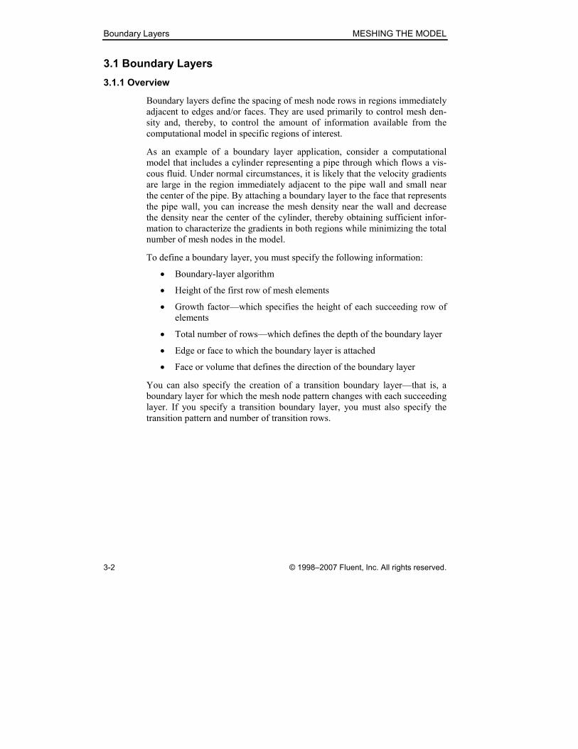
Figure 3-6: Boundary layer dimensions—Uniform algorithm
The First row (a) value specifies the height of the first row (a)—that is, the
absolute distance between the entity to which the boundary layer is attached
and the first row of mesh nodes in the boundary layer. (NOTE: For the Uniform algorithm, the first-row height, a, is uniform across the boundary layer.)
The Growth factor (b/a) value (G) represents the ratio
G b a=
where b is the distance between the first and second rows and a is the height
of the first row. The height of any row in the boundary layer (other than the
first row) is equal to the height of the previous row times the Growth factor (b/a) value.
The Rows value specifies the total number of rows to be included in the
boundary layer.
� NOTE: When you specify the First row (a), Growth factor (b/a), and Rows values, GAMBIT computes the total depth (D) of the boundary layer and dis-
plays the value in the non-editable Depth (D) field on the Create Boundary Layer form.
Boundary Layers MESHING THE MODEL
3-10 © 1998–2007 Fluent, Inc. All rights reserved.
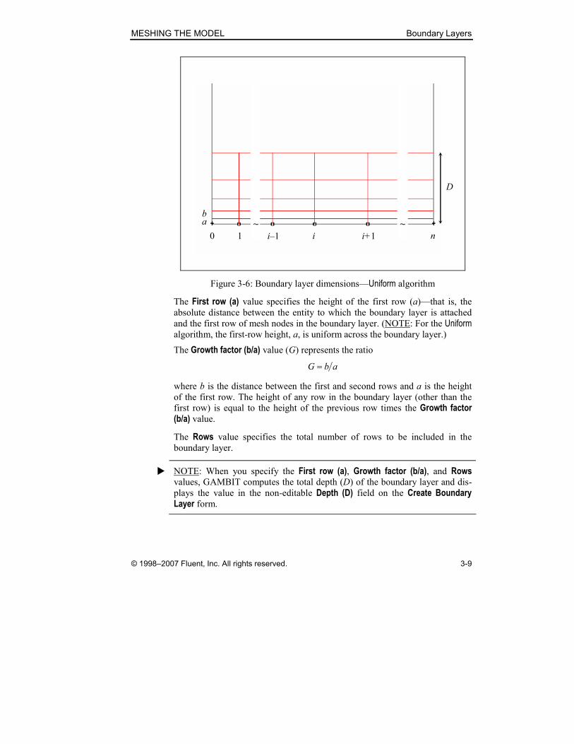
Aspect ratio (first) Algorithm
The Aspect ratio (first) algorithm (see Figure 3-7) definition parameters are as
follows.
• First percent (a/w)
• Growth factor (b/a)
• Rows
0w 1iw − iw
ia
ic
0 1 i–1 i i+1 n
~ ~
0a
0c
ib
Figure 3-7: Boundary layer dimensions—Aspect ratio (first) algorithm
The First percent (a/w) value specifies the height of any first row boundary
layer node ( ia ) as a percentage of mesh interval width at the associated node
on the attachment entity. For interior nodes on the attachment entity, the gen-
eral specification of first-row height can be expressed as
( )1
100 2
i i
i
w wFa
− + =
where ia is the height of the first row at node i, F is the First percent (a/w)
value, and 1iw − and iw are the widths of the attachment-entity mesh intervals
on either side of node i.

MESHING THE MODEL Boundary Layers
© 1998–2007 Fluent, Inc. All rights reserved. 3-11
For exterior nodes on the attachment entity (for example, nodes located at
edge endpoints) the first-row heights can be expressed as
0 0100
Fa w
=
and
1100
n n
Fa w −
=
where 0a and na are the heights of the first rows at the exterior nodes.
The Growth factor (b/a) value (G) represents the ratio
i iG b a=
where ib is the distance between the first and second rows at edge mesh node
i and ia is the height of the first row at node i. (NOTE: For the Aspect ratio
(first) algorithm, the Growth factor (b/a) value is constant across the boundary layer.) The height of any boundary layer row at a given edge node is equal to
the height of the preceding row at that node times the growth factor, G.
The Rows value specifies the total number of rows to be included in the
boundary layer.
� NOTE: When you specify the First percent (a/w), Growth factor (b/a), and Rows values, GAMBIT computes the “last percent” value for the boundary layer
and displays the value in the non-editable Last percent (c/w) field on the Create Boundary Layer form. The Last percent (c/w) value represents the height of the boundary layer top row at any given node relative to the corresponding mesh
interval widths on the attachment entity. The Last percent (c/w) value can be computed from
1RL FG −=
where F and L are the First percent (a/w) and Last percent (c/w) values, respect-ively, G is the Growth factor (b/a) value, and R is the number of Rows.

Boundary Layers MESHING THE MODEL
3-12 © 1998–2007 Fluent, Inc. All rights reserved.
Aspect ratio (last) Algorithm
The Aspect ratio (last) algorithm (see Figure 3-8) definition parameters are as
follows.
• First row (a)
• Rows
• Last percent (c/w)
0w 1iw − iw0 1 i–1 i i+1 n
~ ~a
ic
0c
ib
Figure 3-8: Boundary layer dimensions—Aspect ratio (last) algorithm
The First row (a) value specifies the height of the first row (a)—that is, the
absolute distance between the entity to which the boundary layer is attached
and the first row of mesh nodes in the boundary layer. (NOTE: For the Aspect ratio (last) algorithm, the first-row height, a, is uniform across the boundary
layer.)
The Rows value specifies the total number of rows to be included in the
boundary layer.
The Last percent (c/w) value specifies the height of the boundary layer top row at any node relative to the corresponding mesh interval widths on the attach-
ment entity. At any interior mesh node on the attachment entity (for example,
the endpoints of an attachment edge), the relationship between the top row
MESHING THE MODEL Boundary Layers
© 1998–2007 Fluent, Inc. All rights reserved. 3-13
height ( ic ), the Last percent (c/w) value (L), and the mesh interval widths (w)
can be expressed as
1
100 2
i ii
w wLc − + =
where 1iw − and iw are the widths of the attachment-entity mesh intervals on
either side of node i.
� NOTE: For the Aspect ratio (last) algorithm, the growth factor varies across the
boundary layer and is computed at each mesh node on the attachment entity.
For mesh nodes that are interior to the entity, the growth factor at any node i
can be expressed as
( )1
11
100 2
Ri i
i
w wLG
a
−− + =
where iG is the node-specific growth factor and R is the number of Rows.
Because the growth factor is not constant across the boundary layer, GAMBIT
does not display the Growth factor (b/a) field on the Create Boundary Layer form.
Specifying Internal Continuity
When you attach a boundary layer to a face that constitutes part of a volume,
GAMBIT imprints the boundary layer on all adjoining faces that are also part
of the volume (see Figure 3-9(a)). If you attach boundary layers to two or
more adjoining faces of a volume, the boundary-layer imprints overlap on any
faces that are common neighbors to the adjoining faces (see Figure 3-9(b)).

Boundary Layers MESHING THE MODEL
3-14 © 1998–2007 Fluent, Inc. All rights reserved.
(a) (b)
Imprints Imprint overlaps
Figure 3-9: Boundary-layer imprints (with shaded attachment faces)
The Internal continuity option on the Create Boundary Layer form determines
the manner in which GAMBIT imprints boundary layers on adjoining faces as
well as the mesh pattern in regions of imprint overlap.
• If you do not select the Internal continuity option, GAMBIT imprints
boundary layers on adjoining faces in the manner described above
(Figure 3-10(a)).
• If you select the Internal continuity option, GAMBIT modifies the
mesh patterns in the overlap regions such that the imprints are dove-
tailed together (see Figure 3-10(b)).

MESHING THE MODEL Boundary Layers
© 1998–2007 Fluent, Inc. All rights reserved. 3-15
(a) Internal continuity off (b) Internal continuity on
Figure 3-10: Effect of the Internal continuity option
The effect of the Internal continuity option depends, in part, on the values of two GAMBIT default variables:
• MESH.BLAYER.ANGLE_SMOOTH_FACTOR
• MESH.BLAYER.ADJUST_EDGE_BL_HEIGHT
The ANGLE_SMOOTH_FACTOR default variable specifies whether or not the
boundary-layer angling in the corner region is smoothed out across the adja-
cent edges. The ADJUST_EDGE_BL_HEIGHT default variable specifies
whether or not GAMBIT adjusts the boundary layer heights along the adjacent
edges to maintain constant heights with respect to the edges. Each default
variable can take the values 0 (off) and 1 (on).
Figure 3-11 shows the effect of these default variables on the boundary layer
created using the Internal continuity option. In Figure 3-11(a), both variables are set to zero; therefore, the angling of the boundary layer is confined to the
corner region. In Figure 3-11(b), ANGLE_SMOOTH_FACTOR is set to 1; there-
fore, GAMBIT spreads the boundary-layer angling across the entire edge. In
Figure 3-11(c), ADJUST_EDGE_BL_HEIGHT is also set to 1; therefore,
GAMBIT adjusts the boundary-layer heights to maintain constant heights with
respect to the edges adjacent to the corner.

Boundary Layers MESHING THE MODEL
3-16 © 1998–2007 Fluent, Inc. All rights reserved.
ASF = ANGLE_SMOOTH_FACTOR
AEBH = ADJUST_EDGE_BL_HEIGHT
(a) ASF = 0
AEBH = 0
(b) ASF = 1
AEBH = 0
(c) ASF = 1
AEBH = 1
Figure 3-11: Effect of default variables on Internal continuity option
In addition to affecting the mesh pattern in the imprint-overlap regions, the
Internal continuity option directly affects which types of meshing schemes are
appropriate for volumes to which boundary layers have been applied. For
example, the volume shown in Figure 3-10(b) can be meshed using a Map meshing scheme—resulting in the mesh shown in Figure 3-12(a). By contrast,
the volume shown in Figure 3-10(a) cannot be meshed using a Map scheme,
because the vertex located at the lower right corner of the front face (and
imprint overlap region) is necessarily treated as a Side vertex. To mesh the
volume shown in Figure 3-10(a), it is most reasonable to apply a Pave mesh-
ing scheme to the front face, then apply a Cooper meshing scheme to the
volume, using the front and back faces as source faces (see Figure 3-12(b)).

MESHING THE MODEL Boundary Layers
© 1998–2007 Fluent, Inc. All rights reserved. 3-17
(a) Map volume mesh
(b) Pave face mesh
Cooper volume mesh
Source faces
Figure 3-12: Effect of Internal continuity option on allowable meshing schemes
Specifying the Wedge Corner Shape
GAMBIT allows you to control the shape of the mesh in the region surround-
ing a Corner or Reversal vertex that connects two edges to which boundary lay-ers are attached. To do so, you must select or unselect (default) the Wedge corner shape option on the Create Boundary Layer form. The Wedge corner shape option produces the following effects (see Figure 3-13):
• If you select the Wedge corner shape option, GAMBIT creates a
wedge-shaped boundary-layer region surrounding the connecting
vertex (Figure 3-13(a)).
• If you unselect the Wedge corner shape option, GAMBIT creates a
block-shaped boundary-layer region surrounding the connecting vertex
(Figure 3-13(b)).
If two edges meet at a Corner or Reversal vertex, and each edge possesses a separate boundary layer, then to create a wedge-shaped boundary layer at the
corner, you must select the Wedge corner shape option when creating each separate boundary layer.

Boundary Layers MESHING THE MODEL
3-18 © 1998–2007 Fluent, Inc. All rights reserved.
(a) Wedge corner shape on (b) Wedge corner shape off
Figure 3-13: Effect of Wedge corner shape option
Specifying the Transition Characteristics
The boundary-layer transition characteristics consist of two components:
• Transition pattern
• Number of transition rows
Specifying the Transition Pattern
The transition pattern determines the arrangement of mesh nodes in the
region near the outermost row of the boundary layer. Boundary layer transi-
tion patterns are defined by the ratio
A:B
where B is the number of mesh intervals in a given row and A is the number of
mesh intervals in the immediately preceding full row. GAMBIT allows you to
specify any of four transition patterns—1:1, 4:2, 3:1, or 5:1.
Figure 3-14 shows four different two-row boundary layers representing each
of the four transition patterns listed above.

MESHING THE MODEL Boundary Layers
© 1998–2007 Fluent, Inc. All rights reserved. 3-19
(a) 1:1 (b) 4:2
(c) 3:1 (d) 5:1
Figure 3-14: Boundary layer transition patterns
� NOTE: Edges can host any of the four transition patterns, but faces can host
only the 1:1 transition pattern.
Specifying the Number of Transition Rows
When you specify any transition pattern other than 1:1, you must also specify
the number of transition rows—that is, the number of outermost rows to
which the transition pattern is applied. GAMBIT applies the 1:1 pattern to all rows other than the transition rows. Figure 3-15 shows the effect of the num-
ber of transition rows on a boundary layer consisting of three rows with the
transition pattern 4:2.

Boundary Layers MESHING THE MODEL
3-20 © 1998–2007 Fluent, Inc. All rights reserved.
(a) One transition row (b) Two transition rows
Figure 3-15: Effect of number of transition rows
Specifying the Attachment Entity
To define the location of a boundary layer, you must specify the edge or face
to which the boundary layer is attached. If the edge or face is shared by two or
more faces or volumes, respectively, you must also specify the face or volume
that defines the direction of the boundary layer. For example, each edge of a
rectangular brick volume is shared by two rectangular faces. If you attach a
boundary layer to one of the edges of the volume, you must specify which of
the corresponding faces defines the direction of the boundary layer.
Specifying the Boundary Layer Direction
When you specify an edge or face to which to attach a boundary layer,
GAMBIT highlights the edge or face in the graphics window and displays the
following items:
• The boundary layer as currently specified
• An arrow that indicates the direction of the boundary layer
You can change the direction of the boundary layer either by means of the
Attachment (Edge or Face) list box on the Create Boundary Layer form or by
means of the mouse.
MESHING THE MODEL Boundary Layers
© 1998–2007 Fluent, Inc. All rights reserved. 3-21
� NOTE: If the boundary-layer attachment entity serves as an attachment entity
for a size function or is part of a higher-topology entity to which a size func-
tion is attached, GAMBIT might or might not reflect the size-function defini-
tion in the temporary display of the boundary layer. Specifically, the
boundary-layer display reflects the definition of the size function only if the
background grid for the size function has already been generated—for
example, by meshing an edge that is also part of the size-function attachment
entity.
Changing Direction by Means of the List Box
When you specify an edge or face in the Attachment list box on the Create Boundary Layer form, the list box displays both the specified entity itself and
the face or volume that defines the direction of the boundary layer. To change
the direction of the boundary layer by means of the list box, you can perform
either of the following operations.
1. Specify the edge or face again in the Attachment list box
2. Use the Edge List or Face List paired pick-list form to specify the entity
and direction of the boundary layer (see “Using the Edge List or Face
List Form,” below).
Changing Direction by Means of the Mouse
To change the direction of the boundary layer by means of the mouse, Shift-
middle-click the entity to which the boundary layer is attached.
Specifying Multiple Boundary Layers
GAMBIT allows you to apply a given boundary layer definition to more than
one edge or face at a time. To do so, you must include in the Attachment entity pick list all of the entities to which the currently defined boundary layer is to
be attached.
You can add an edge or face to the Attachment entity pick list on one of the following ways:
• Input the entity name directly in the Attachment list box or select the entity from the entity pick-list form
• Pick the entity in the graphics window

Boundary Layers MESHING THE MODEL
3-22 © 1998–2007 Fluent, Inc. All rights reserved.
Smoothing the Mesh at Boundary Layer Transition Points
If you attach 2-D boundary layers to adjacent edges that share a common face
or attach 3-D boundary layers to adjacent faces that share a common volume,
GAMBIT automatically smoothes the resulting mesh at the transition points
between the boundary layers. You can control the range of elements over
which the boundary layers are smoothed by means of the HEIGHT_TRANSIT_
RATIO default variable.
As an example of mesh smoothing at boundary layer transition points, con-
sider the 2-D boundary layers shown in Figure 3-16. In this case, the boundary
layers are attached to adjacent edges that constitute one side of a square face.
They differ from each other only with respect to their growth factors.
Figure 3-16: Example 2-D boundary layers on adjacent edges
If you retain the default value for the HEIGHT_TRANSIT_RATIO default
variable and mesh the face shown in Figure 3-16, GAMBIT creates the mesh
shown in Figure 3-17. In this case, the discontinuity between the boundary
layers is smoothed over three intervals on either side of the transition point.

MESHING THE MODEL Boundary Layers
© 1998–2007 Fluent, Inc. All rights reserved. 3-23
Transition region (3 intervals/side)
Figure 3-17: Mesh with boundary layer smoothing at transition point
As noted above, you can use the HEIGHT_TRANSIT_RATIO default variable
to control the number of intervals over which the mesh is smoothed. The
effect of the default variable depends on whether its value is greater or less
than one (1) and can be summarized as follows:
• HEIGHT_TRANSIT_RATIO ≤ 1—Fraction of total intervals on either
side of the transition point
• HEIGHT_TRANSIT_RATIO > 1—Number of transition intervals on
either side of the transition point
By default, the HEIGHT_TRANSIT_RATIO value is equal to 0.5; therefore, the
boundary layer is smoothed over half of the intervals on each side of the
transition point (see Figure 3-17, above). If you specify a HEIGHT_TRANSIT_
RATIO value greater than one (1), GAMBIT rounds the value up or down to
the closest integer and uses the rounded value as the number of intervals on
either side of the transition point over which the mesh is smoothed. For
example, if you specify a value of 2 for the default variable, GAMBIT
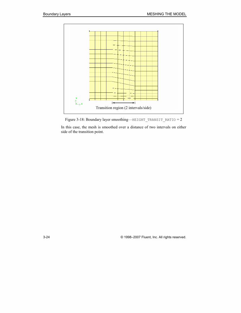
smoothes the mesh as shown in Figure 3-18.
Boundary Layers MESHING THE MODEL
3-24 © 1998–2007 Fluent, Inc. All rights reserved.
Transition region (2 intervals/side)
Figure 3-18: Boundary layer smoothing—HEIGHT_TRANSIT_RATIO = 2
In this case, the mesh is smoothed over a distance of two intervals on either
side of the transition point.

MESHING THE MODEL Boundary Layers
© 1998–2007 Fluent, Inc. All rights reserved. 3-25
Using the Create Boundary Layer Form
To open the Create Boundary Layer form (see below), click the Create Boundary Layer command button on the Mesh/Boundary Layer subpad.
The Create Boundary Layer form contains the following specifications.
���� Show displays the boundary layer(s) in the graphics window as they
are created and defined.
Boundary Layers MESHING THE MODEL
3-26 © 1998–2007 Fluent, Inc. All rights reserved.
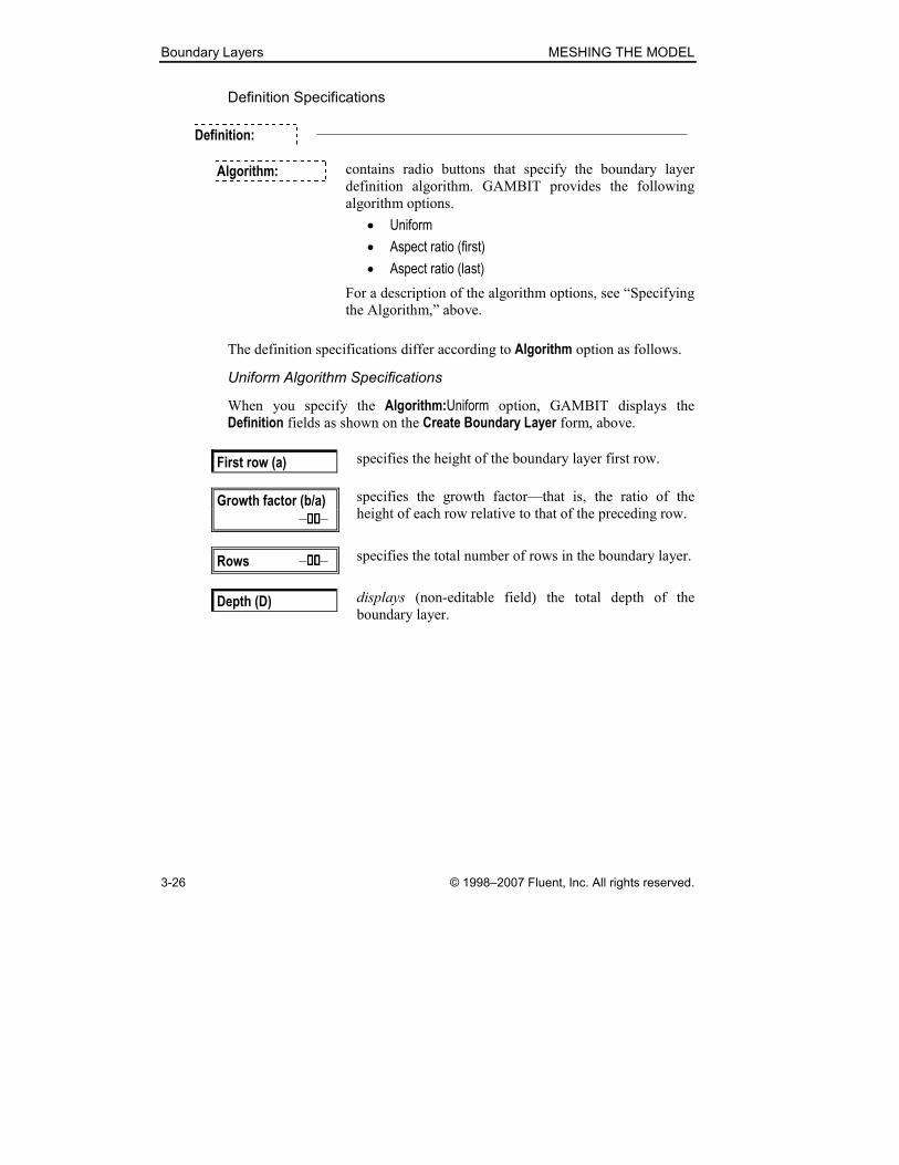
Definition Specifications
Definition: —————————————————————————
Algorithm: contains radio buttons that specify the boundary layer
definition algorithm. GAMBIT provides the following
algorithm options.
• Uniform
• Aspect ratio (first)
• Aspect ratio (last)
For a description of the algorithm options, see “Specifying
the Algorithm,” above.
The definition specifications differ according to Algorithm option as follows.
Uniform Algorithm Specifications
When you specify the Algorithm:Uniform option, GAMBIT displays the
Definition fields as shown on the Create Boundary Layer form, above.
First row (a) specifies the height of the boundary layer first row.
Growth factor (b/a)
–��������–
specifies the growth factor—that is, the ratio of the
height of each row relative to that of the preceding row.
Rows –��������– specifies the total number of rows in the boundary layer.
Depth (D) displays (non-editable field) the total depth of the
boundary layer.
MESHING THE MODEL Boundary Layers
© 1998–2007 Fluent, Inc. All rights reserved. 3-27
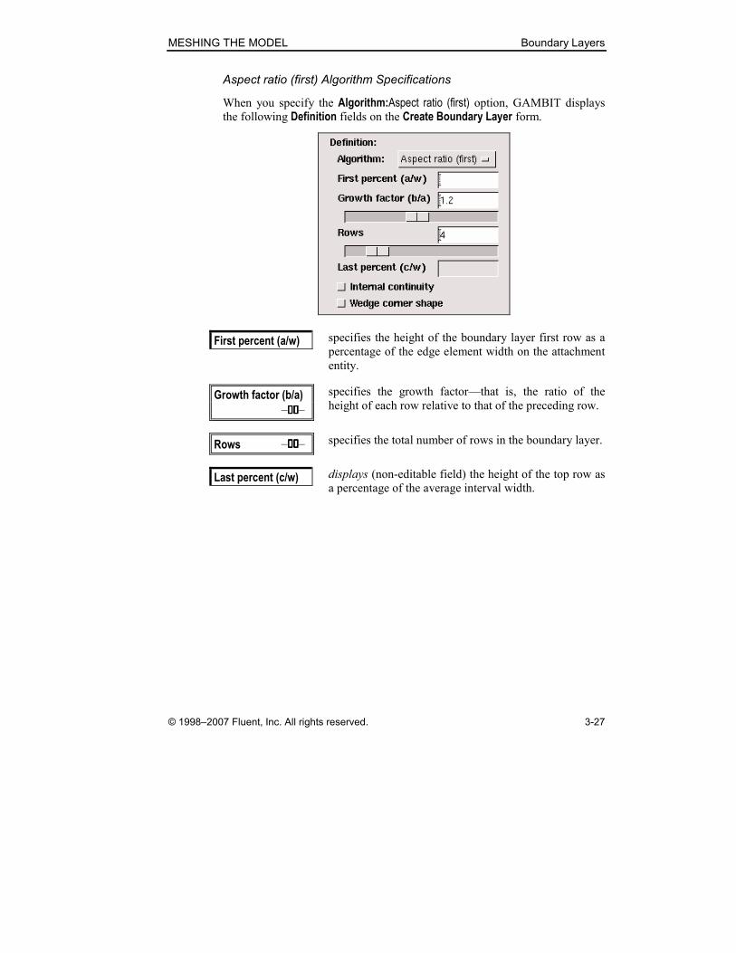
Aspect ratio (first) Algorithm Specifications
When you specify the Algorithm:Aspect ratio (first) option, GAMBIT displays
the following Definition fields on the Create Boundary Layer form.
First percent (a/w) specifies the height of the boundary layer first row as a
percentage of the edge element width on the attachment
entity.
Growth factor (b/a)
–��������–
specifies the growth factor—that is, the ratio of the
height of each row relative to that of the preceding row.
Rows –��������– specifies the total number of rows in the boundary layer.
Last percent (c/w) displays (non-editable field) the height of the top row as
a percentage of the average interval width.

Boundary Layers MESHING THE MODEL
3-28 © 1998–2007 Fluent, Inc. All rights reserved.
Aspect ratio (last) Algorithm Specifications
When you specify the Algorithm:Aspect ratio (last) option, GAMBIT displays
the following Definition fields on the Create Boundary Layer form.
First row (a) specifies the height of the boundary layer first row.
Rows –��������– specifies the total number of rows in the boundary layer.
Last percent (c/w) specifies the height of the top row as a percentage of the
average interval width.
General Specifications
The following Definition specifications are common to all of the Algorithm options.
���� Internal continuity
specifies that boundary-layer imprints are dovetailed in
overlapping regions (see “Specifying Internal Continuity,”
above).
���� Wedge corner shape
specifies that the boundary-layer forms a wedge shape in
the region surrounding a Corner or Reversal vertex (see “Specifying the Wedge Corner Shape,” above).

MESHING THE MODEL Boundary Layers
© 1998–2007 Fluent, Inc. All rights reserved. 3-29
Transition Pattern Specifications
Transition Pattern:
contains four radio buttons that specify the transition pattern.
The pattern options are 1:1, 4:2, 3:1, and 5:1. (See “Specifying the Transition ,” above.)
Transition –��������–
Rows
specifies the number of transition rows for transition pat-
terns 4:2, 3:1, and 5:1. (NOTE: You must use the slide bar,
rather than the associated text box, to set the number of
transition rows.)
Attachment Specifications
Attachment: —————————————————————————
Edges � Faces
specifies whether the boundary layer is attached to an edge
or a face.
Edges �
Faces
specifies the edge or face to which the boundary layer is
attached. (NOTE: When you click the pick list button
on the Attachment entity list box, GAMBIT opens a
paired pick list form titled Edge List or Face List. For instructions in using the paired pick list form, see
“Using the Edge List or Face List Form,” below.)
Label specifies a label for the boundary layer.

Boundary Layers MESHING THE MODEL
3-30 © 1998–2007 Fluent, Inc. All rights reserved.
Using the Edge List or Face List Form
When you specify an edge or face to which a boundary layer is attached,
GAMBIT adds the edge or face to a paired pick list. The paired pick list
includes both the attachment entity itself (edge or face) and the entity that
defines the direction of the boundary layer (face or volume). You can modify
the edge or face paired pick list by means of either the Edge List or Face List pick-list form, respectively. Both forms operate according to the following
general principles described for the Edge List form.
To open the Edge List form (see below), select Edge in the Attachment field on the Create Boundary Layer form and click the associated pick list button.
The Edge List paired pick-list form operates in a manner similar to that of con-
ventional pick-list forms (see GAMBIT User’s Guide, Chapter 3). It differs
from the conventional forms only in that the Picked scroll list includes two columns.
• The left column lists the edge to which the boundary layer is attached.
• The right column lists the face that defines the direction of the bound-
ary layer.

MESHING THE MODEL Boundary Layers
© 1998–2007 Fluent, Inc. All rights reserved. 3-31
When you add an edge to the Picked scroll list by means of the right-arrow
command button, GAMBIT adds the edge to the Edge column and automati-
cally includes one of its associated faces in the Face column. (The face defines
the direction of the boundary layer.) If you add the same edge again to the
Picked scroll list, GAMBIT creates a second entry for the edge in the Edge column and includes another of its associated faces in the Face column. When
the Face column includes all faces associated with a given edge, GAMBIT
removes that edge from the Available column.
Boundary Layers MESHING THE MODEL
3-32 © 1998–2007 Fluent, Inc. All rights reserved.
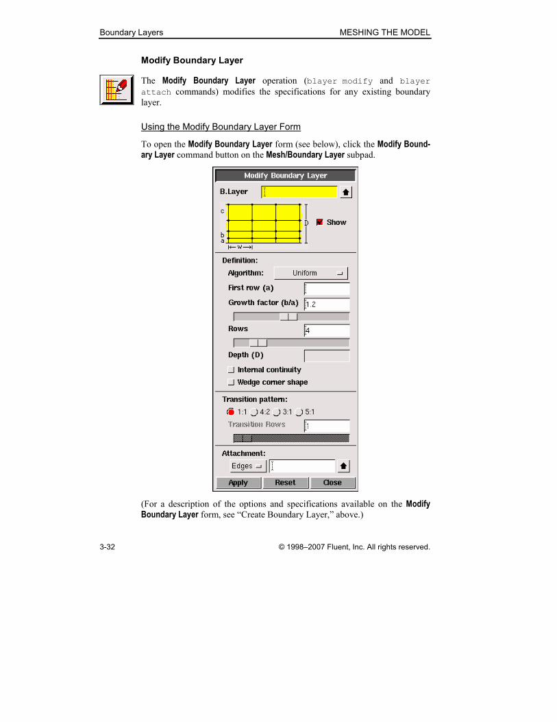
Modify Boundary Layer
The Modify Boundary Layer operation (blayer modify and blayer
attach commands) modifies the specifications for any existing boundary
layer.
Using the Modify Boundary Layer Form
To open the Modify Boundary Layer form (see below), click the Modify Bound-ary Layer command button on the Mesh/Boundary Layer subpad.
(For a description of the options and specifications available on the Modify Boundary Layer form, see “Create Boundary Layer,” above.)

MESHING THE MODEL Boundary Layers
© 1998–2007 Fluent, Inc. All rights reserved. 3-33
View 3D Boundary Layers
The View 3D Boundary Layers operation (blayer mesh command) allows
you to examine volume meshes in regions affected by 3-D boundary layers.
When you execute the View 3D Boundary Layers command for any 3-D
boundary layer, GAMBIT meshes the volume associated with the boundary
layer, renders the mesh invisible outside the boundary layer region, and auto-
matically opens the Examine Mesh form.
Figure 3-19 illustrates the effect of the View 3D Boundary Layers operation for a cube with a uniform boundary layer attached to two adjoining faces. In this
case, the boundary layer was created using the Internal continuity option; therefore, the boundary layer dovetails in its overlapping regions.
(a) Cube with boundary layer (b) Boundary layer view
Figure 3-19: View 3D Boundary Layers operation
If you execute the View 3D Boundary Layers operation for the boundary layer shown in Figure 3-19(a), GAMBIT meshes the cube, renders the mesh invisi-
ble outside the boundary layer region, and automatically opens the Examine Mesh form to display the mesh (Figure 3-19(b)). By default, GAMBIT selects
the Range option on the Examine Mesh form and displays all volume elements
in the boundary layer region; however, you can use any of the Examine Mesh options (for example, Plane or Sphere) to customize the mesh display.

Boundary Layers MESHING THE MODEL
3-34 © 1998–2007 Fluent, Inc. All rights reserved.
� NOTE: It is advisable to close the Examine Mesh form before executing subse-
quent GAMBIT operations. When you close the Examine Mesh form,
GAMBIT automatically executes an undo command to undo the blayer
mesh command that generated the boundary layer mesh(es).
Using the View 3D Boundary Layers Form
To open the View 3D Boundary Layers form (see below), click the View com-
mand button on the Mesh/Boundary Layer subpad.
The View 3D Boundary Layers form includes the following specification.
B.L.s � specifies the boundary layer region(s) to be displayed.

MESHING THE MODEL Boundary Layers
© 1998–2007 Fluent, Inc. All rights reserved. 3-35
Modify Boundary Layer Label
The Modify Boundary Layer Label operation (blayer modify command)
changes the label associated with any boundary layer.
Using the Modify Boundary Layer Label Form
To open the Modify Boundary Layer Label form (see below), click the Modify Label command button on the Mesh/Boundary Layer subpad.
The Modify Boundary Layer Label form includes the following specifications.
B.L. � specifies the boundary layer to be modified.
Label specifies a new label for the boundary layer.
Boundary Layers MESHING THE MODEL
3-36 © 1998–2007 Fluent, Inc. All rights reserved.
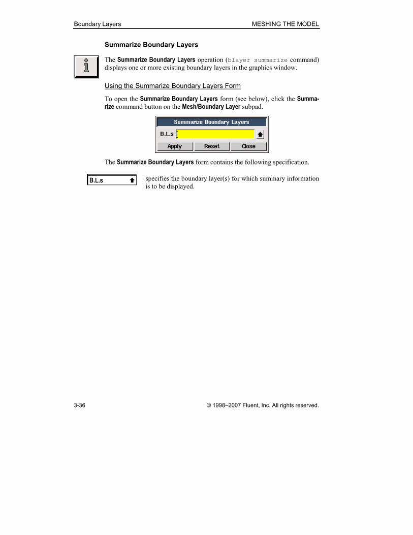
Summarize Boundary Layers
The Summarize Boundary Layers operation (blayer summarize command)
displays one or more existing boundary layers in the graphics window.
Using the Summarize Boundary Layers Form
To open the Summarize Boundary Layers form (see below), click the Summa-rize command button on the Mesh/Boundary Layer subpad.
The Summarize Boundary Layers form contains the following specification.
B.L.s � specifies the boundary layer(s) for which summary information
is to be displayed.

MESHING THE MODEL Boundary Layers
© 1998–2007 Fluent, Inc. All rights reserved. 3-37
Delete Boundary Layers
The Delete Boundary Layers operation (blayer delete command) deletes
one or more existing boundary layers.
Using the Delete Boundary Layers Form
To open the Delete Boundary Layers form (see below), click the Delete com-
mand button on the Mesh/Boundary Layers subpad.
The Delete Boundary Layers form includes the following specification.
B.L.s � specifies the boundary layer(s) to be deleted.
Edge Meshing Commands MESHING THE MODEL
3-38 © 1998–2007 Fluent, Inc. All rights reserved.
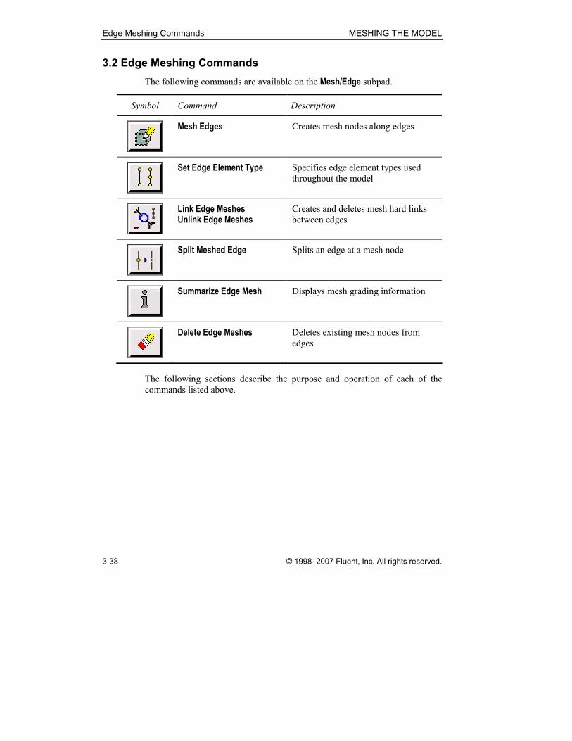
3.2 Edge Meshing Commands
The following commands are available on the Mesh/Edge subpad.
Symbol Command Description
Mesh Edges Creates mesh nodes along edges
Set Edge Element Type Specifies edge element types used
throughout the model
Link Edge Meshes Unlink Edge Meshes
Creates and deletes mesh hard links
between edges
Split Meshed Edge Splits an edge at a mesh node
Summarize Edge Mesh Displays mesh grading information
Delete Edge Meshes Deletes existing mesh nodes from
edges
The following sections describe the purpose and operation of each of the
commands listed above.
MESHING THE MODEL Edge Meshing Commands
© 1998–2007 Fluent, Inc. All rights reserved. 3-39
3.2.1 Mesh Edges
The Mesh Edges operation (edge mesh, edge modify, edge picklink,
and edge pickunlink commands) grades or meshes any or all edges in the
model. When you grade an edge, GAMBIT applies the mesh node spacing
specifications but does not create mesh nodes on the edge. When you mesh an
edge, GAMBIT creates mesh nodes according to the specifications.
To perform a grading or meshing operation, you must specify the following
parameters:
• Edge(s) to which the grading specifications apply
• Grading scheme
• Mesh node spacing (number of intervals)
• Edge meshing options
Specifying Edges
When you specify one or more edges for a grading or meshing operation, you
must specify the following options:
• Soft-link
• Reverse
When you soft-link two or more edges, GAMBIT links the edges for meshing
purposes so that any grading or meshing specifications applied to one edge
can be simultaneously applied to the other edges as well. When you reverse an
edge, GAMBIT reverses the sense of the edge; therefore, any directional
grading scheme associated with the edge is also reversed.
In addition to the soft-link and reverse options described above, GAMBIT
allows you to specify whether or not to impose the grading parameters of the
first edge specified in the Edges list on all other parameters in the list (see
“Imposing First-Edge Grading and Spacing Parameters,” below).
Soft-linking Edges
When you specify more than one edge for a grading or meshing operation,
GAMBIT allows you to create soft links between the specified edges. When
you grade or mesh an edge that is soft-linked to other edges, you can simulta-
neously apply the grading or meshing specifications to all of the edges that are
soft-linked to the specified edge.

Edge Meshing Commands MESHING THE MODEL
3-40 © 1998–2007 Fluent, Inc. All rights reserved.
Forming, Maintaining, and Breaking Soft Links
When you specify two or more edges for a grading or meshing operation, you
must specify the status of any soft links that involve the edges. The three soft-
link status options are as follows:
• Form—forms soft links between the edges
• Maintain—maintains all existing soft links that involve the edges
• Break—breaks any existing soft links that involve the edges
When you Form soft links between two or more edges, GAMBIT creates a
“chain” of links between the specified edges. If you form a soft link involving
an edge that is part of an existing soft-link chain, GAMBIT breaks the existing
soft link associated with the edge. That is, no single edge is allowed to consti-
tute part of more than one soft-link chain.
When you Maintain soft links, GAMBIT does not form or break any existing
soft links associated with the specified edge(s).
When you Break a soft link associated with an edge, GAMBIT removes the
edge from the soft-link chain but does not break any other soft links in the
chain. That is, any other edges that are part of the soft-link chain remain soft-
linked to each other.
Grading or Meshing Soft-link Chains
When you grade or mesh an edge that constitutes part of an existing soft-link
chain, GAMBIT allows you to specify whether the grading or meshing speci-
fications apply to all edges that belong to the chain (the Pick with links option). The general rules pertaining to the Pick with links option are as follows.
• To grade or mesh all edges that belong to an existing chain, select the
Pick with links option on the Mesh Edges form and specify one of the
edges that belongs to the chain.
• To grade or mesh an edge that constitutes part of a soft-link chain
without grading or meshing the other edges in the chain, unselect the
Pick with links option before specifying the edge. To maintain all links
between the specified edge and all edges to which it is soft-linked,
select the Soft links:Maintain option before specifying the edge.

MESHING THE MODEL Edge Meshing Commands
© 1998–2007 Fluent, Inc. All rights reserved. 3-41
Reversing Edges
When you mesh an edge using a non-uniform grading scheme, GAMBIT
grades or meshes the edge relative to its sense. For example, if you mesh an
edge using a First Length scheme (see below) and specify a first interval length
of 2, GAMBIT locates the first mesh node at a distance of 2 units from the
edge start vertex.
When you specify edges for a grading or meshing operation, GAMBIT allows
you to change their respective senses by means of the Reverse command
button on the Mesh Edges form. If you reverse the sense of an edge the grad-
ing of which is non-uniform, the grading or meshing scheme is also reversed.
For example, if you mesh an edge using a First Length grading scheme and
specify a first interval length of 2, then click Reverse to reverse the sense of the edge, GAMBIT meshes the edge such that the last mesh node is located at
a distance of 2 from the edge end vertex.
If you apply the Reverse option to an edge that is part of a soft-link chain and select the Pick with links option, GAMBIT reverses the sense and, therefore,
the grading of all edges in the chain.
Imposing First-Edge Grading and Spacing Parameters
When you specify a set of edges for grading and/or meshing, you can also
determine whether or not to impose the grading parameters of the first edge
specified in the Edges list on all other edges in the list. To impose the first-
edge grading and/or spacing parameters on the other specified edges, you
must select the Use first edge settings option on the Mesh Edges form. By
default, the Use first edge settings option is selected.
Grading Parameters
If you specify a set of edges at least one of which differs from the others with
respect to its Grading parameters, the Use first edge settings option produces the following effects on the Grading section of the Mesh Edges form.
• If you select the Use first edge settings option, the Grading settings remain active and display the settings of the first edge specified in the
Edges list.
• If you unselect the Use first edge settings option and select an edge the grading parameters of which differ from the currently displayed para-
meters, the Grading settings become inactive and the displayed settings
are those of the most recently selected edge.
Edge Meshing Commands MESHING THE MODEL
3-42 © 1998–2007 Fluent, Inc. All rights reserved.
Spacing Parameters
The behavior of the Spacing section of the Mesh Edges form is identical to
that of the Grading section (see above) with respect to the Use first edge settings option.
� NOTE: The Grading and Spacing sections of the Mesh Edges form behave
independently of each other with respect to the Use first edge settings option.
Specifying the Grading Scheme
GAMBIT provides the following types of edge mesh grading schemes.
• Successive Ratio
• First Length
• Last Length
• First Last Ratio
• Last First Ratio
• Exponent
• Bi-exponent
• Bell Shaped
The first six schemes listed above are non-symmetric schemes—that is, they
can produce grading patterns that are not necessarily symmetric about the
center of the edge. The last two schemes are symmetric schemes—that is, they
are constrained to produce grading patterns that are symmetric about the
center of the edge.

MESHING THE MODEL Edge Meshing Commands
© 1998–2007 Fluent, Inc. All rights reserved. 3-43
� NOTE: When you grade or mesh an edge that is connected to one or more
edges that are already graded or meshed, GAMBIT provides the means to
ensure that the new grading is similar to the existing grading(s) in the
region(s) surrounding the connecting vertex (or vertices). This specification is
accomplished by means of the MESH.EDGE.FLEXIBLE_GRADING default
variable.
• If you set the variable to 0 (default), GAMBIT applies the settings speci-
fied on the Mesh Edges form without regard to the existing grad-
ing/meshing parameters(s) on the already graded or meshed edges.
• If you set the variable to 1, GAMBIT ignores the settings specified on
the Mesh Edges form and grades the edge such that its first interval
length in the region adjacent to the connecting vertex is similar to that on
the already meshed or graded edge(s) to which it is connected. If the
edge is connected to graded/meshed edges at both endpoint vertices,
GAMBIT uses a single-sided grading scheme the first and last interval
lengths of which are similar to the lengths of the intervals on the edges
to which it is connected (on each end). If the edge is connected to multi-
ple graded or meshed edges at a single vertex, GAMBIT averages the
lengths on the graded/meshed edges in the region surrounding the con-
necting vertex to determine the appropriate first interval length on the
ungraded edge.
Non-Symmetric Grading Schemes
For each of the non-symmetric grading schemes, GAMBIT positions mesh
nodes along the edge such that the ratio of any two succeeding interval lengths
is constant. That is,
Rl
l
i
i =+1
where il and 1+il are the lengths of intervals i and i+1, respectively, and R is a
fixed value (see Figure 3-20). For any given number of intervals (n), the grad-
ing schemes differ from each other only with respect to the manner in which
GAMBIT determines the value of the interval length ratio, R.

Edge Meshing Commands MESHING THE MODEL
3-44 © 1998–2007 Fluent, Inc. All rights reserved.
. . .
Start End
Interval lengths
Mesh node location
Constant1 ==+ Rl
l
i
i
1l 2l 3l 1−nl nl
Figure 3-20: Edge mesh grading parameters
� NOTE: When you mesh an edge, GAMBIT positions the mesh nodes based,
in part, on the edge element type as currently specified on the Set Edge Element Type form (see “Set Edge Element Type,” below).
• If you specify 2-node edge elements, GAMBIT creates mesh nodes
only at the endpoints of the edge mesh intervals.
• If you specify 3-node edge elements, GAMBIT creates an additional
mesh node at the center of each mesh interval.
For example, if you specify the 3-node edge element type and grade an edge
such that it includes five mesh intervals, GAMBIT creates 11 mesh nodes on
the edge. Six of the mesh nodes define the endpoints of the mesh intervals; the
other five are located at the centers of the intervals.
The mesh node locations presented throughout this section are based on the
2-node edge element type.
MESHING THE MODEL Edge Meshing Commands
© 1998–2007 Fluent, Inc. All rights reserved. 3-45
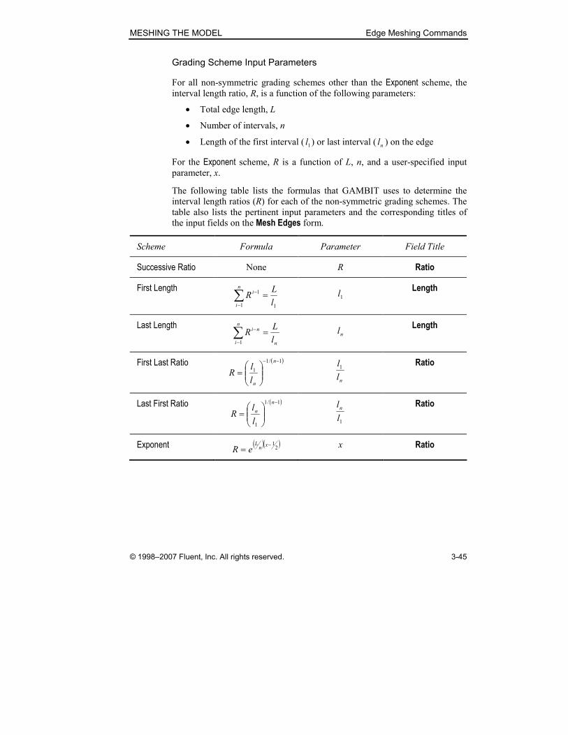
Grading Scheme Input Parameters
For all non-symmetric grading schemes other than the Exponent scheme, the
interval length ratio, R, is a function of the following parameters:
• Total edge length, L
• Number of intervals, n
• Length of the first interval ( 1l ) or last interval ( nl ) on the edge
For the Exponent scheme, R is a function of L, n, and a user-specified input
parameter, x.
The following table lists the formulas that GAMBIT uses to determine the
interval length ratios (R) for each of the non-symmetric grading schemes. The
table also lists the pertinent input parameters and the corresponding titles of
the input fields on the Mesh Edges form.
Scheme Formula Parameter Field Title
Successive Ratio None R Ratio
First Length
11
1
l
LR
n
i
i =∑−
− 1l Length
Last Length
n
n
i
ni
l
LR =∑
−
−
1
nl Length
First Last Ratio ( )1/1
1
−−
=
n
nl
lR
nl
l1 Ratio
Last First Ratio ( )1/1
1
−
=
n
n
l
lR
1l
ln Ratio
Exponent ( )( )2
1−=
xn
L
eR x Ratio

Edge Meshing Commands MESHING THE MODEL
3-46 © 1998–2007 Fluent, Inc. All rights reserved.
As an example of the differences between input parameters for the non-sym-
metric grading schemes, consider the straight, graded edge shown in Figure
3-21. The edge possesses a length of 15 units (L = 15) and is to be graded
such that it contains four intervals (n = 4), each of which is twice as long as
the previous interval (R = 2).
Edge length: L = 15
Number of intervals: n = 4
Ratio: R = 2
Start End
11 =l 22 =l 84 =l43 =l
Figure 3-21: Edge grading example
The grading parameters required by each of the non-symmetric schemes to
create the grading shown in Figure 3-21 are as follows.
Scheme Ratio Length
Successive Ratio 2
First Length 1
Last Length 8
First Last Ratio 0.125
Last First Ratio 8
Exponent 0.6848
MESHING THE MODEL Edge Meshing Commands
© 1998–2007 Fluent, Inc. All rights reserved. 3-47
Double-Sided Grading
When you grade or mesh an edge using any non-symmetric scheme other than
the Last Length or Exponent schemes, GAMBIT allows you to specify whether
the grading scheme is single-sided or double-sided. (NOTE: To apply an Expo-nent scheme to two segments of a single edge, use the Bi-exponent symmetric
grading scheme (see below).) Double-sided grading differs from single-sided
grading in that the edge is divided into two separate segments for grading
purposes, and each segment is graded according to its own grading parameter.
(NOTE: GAMBIT does not allow you to specify different grading schemes
for each segment.)
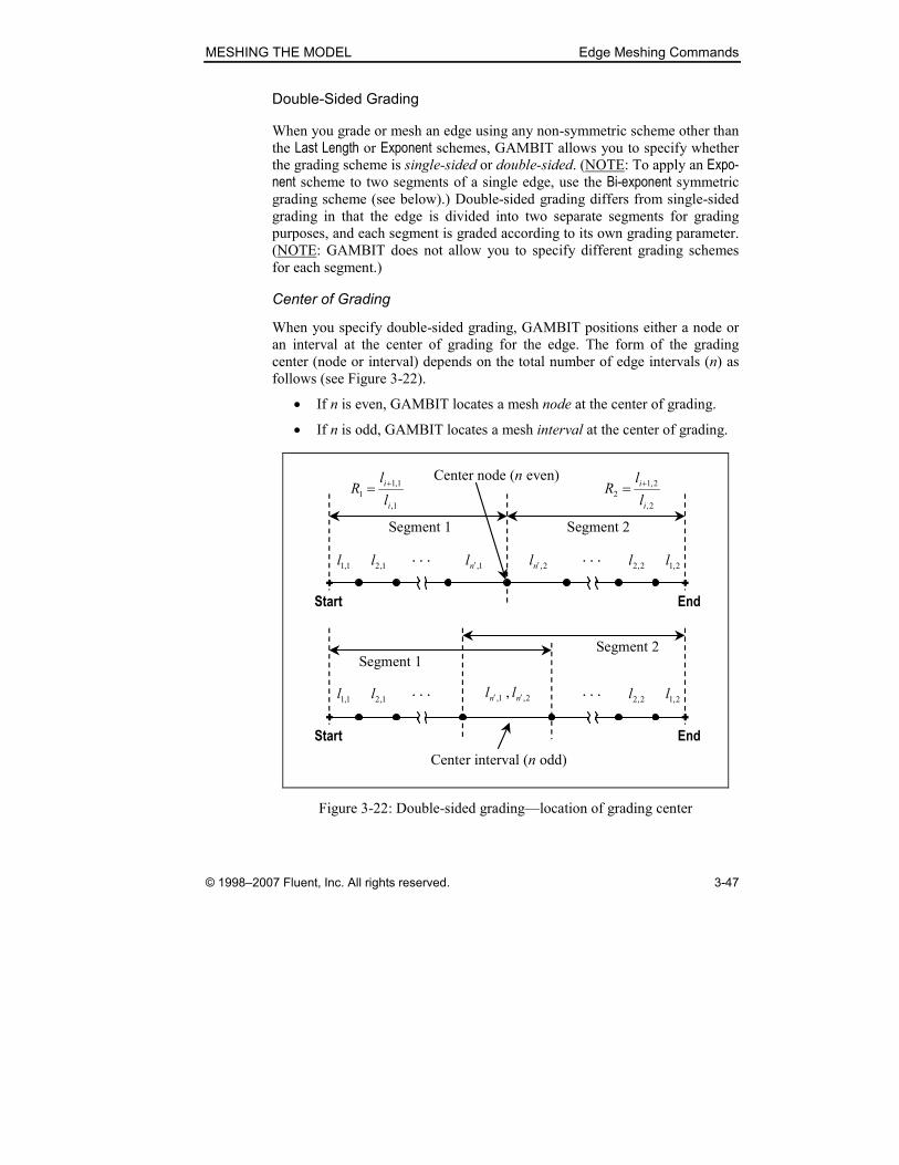
Center of Grading
When you specify double-sided grading, GAMBIT positions either a node or
an interval at the center of grading for the edge. The form of the grading
center (node or interval) depends on the total number of edge intervals (n) as
follows (see Figure 3-22).
• If n is even, GAMBIT locates a mesh node at the center of grading.
• If n is odd, GAMBIT locates a mesh interval at the center of grading.
Start End
Center node (n even)
. . . . . .
Segment 1 Segment 2
Start End
Center interval (n odd)
. . . . . .
Segment 1Segment 2
1,
1,1
1
i
i
l
lR
+=2,
2,1
2
i
i
l
lR
+=
1,1l 1,2l 1,nl ′ 2,nl ′ 2,2l 2,1l
1,1l 1,2l 2,2l 2,1l2,1, , nn ll ′′
Figure 3-22: Double-sided grading—location of grading center

Edge Meshing Commands MESHING THE MODEL
3-48 © 1998–2007 Fluent, Inc. All rights reserved.
The location of the center node (n even) or the location and size of the center
interval (n odd) is determined according to the following rules.
• If n is even, GAMBIT grades the edge such that the lengths of the
intervals on either side of the center node are equal.
• If n is odd, GAMBIT grades the edge such that the length of the center
interval conforms to the meshing parameters specified for both seg-
ments of the edge.
As an example of the effect of interval number on double-sided grading, con-
sider the edge shown in Figure 3-23. The edge possesses a length of 8 units
and is to be graded such that 1R = 1.5 and 2R = 1.0.
Start End
511,
1,1
1 .l
lR
i
i == +01
2
21
2 .l
lR
i,
,i == +
8=L
Figure 3-23: Double-sided grading scheme—example
Figure 3-24 and Figure 3-25 show the effect of specifying 7 and 8 intervals,
respectively, on the grading of the edge shown in Figure 3-23.

MESHING THE MODEL Edge Meshing Commands
© 1998–2007 Fluent, Inc. All rights reserved. 3-49
Start End
Center interval
n = 7
511 .R =
011 .R =
1,1l 1,2l 1,3l 2,41,4 ll = 2,3l 2,2l 2,1l
Figure 3-24: Double-sided grading scheme, n = 7
Start End
Center node
n = 8
511 .R =
011 .R =
1,1l 1,2l 1,3l 2,3l 2,2l 2,1l1,4l 2,4l
Figure 3-25: Double-sided grading scheme, n = 8

Edge Meshing Commands MESHING THE MODEL
3-50 © 1998–2007 Fluent, Inc. All rights reserved.
The following table lists the interval lengths for the double-sided grading
schemes shown in Figure 3-24 and Figure 3-25.
Interval Figure 3-24 (n = 7) Figure 3-25 (n = 8)
1 0.44 0.37
2 0.66 0.56
3 0.99 0.83
4 1.48 1.25
5 1.48 1.25
6 1.48 1.25
7 1.48 1.25
8 1.25
Note that, if you specify seven intervals for the edge (n = 7), GAMBIT grades
the edge such that the length of the center interval satisfies the grading ratios
for both edge segments (see Figure 3-24). That is,
48.12,41,4 == ll
5.199.0
48.1
1,3
1,4 ==l
l
and 0.148.1
48.1
2,3
2,4 ==l
l .
If you specify eight intervals for the edge (n = 8), GAMBIT grades the edge
such that the lengths of the intervals on either side of the center node are equal
(see Figure 3-25). That is,
25.12,41,4 == ll
5.183.0
25.1
1,3
1,4 ==l
l
and 0.125.1
25.1
2,3
2,4 ==l
l .

MESHING THE MODEL Edge Meshing Commands
© 1998–2007 Fluent, Inc. All rights reserved. 3-51
Double-Sided Grading Input Parameters
When you grade or mesh an edge by means of a double-sided grading scheme,
you must specify grading parameters for both segments of the edge. The fol-
lowing table lists double-sided grading input parameters as they appear on the
Mesh Edges form for each of the available grading schemes. (For descriptions
of the parameters, see Figure 3-22.)
Scheme Parameter Field Title
Successive Ratio 1R
2R
Ratio 1
Ratio 2
First Length 1,1l
2,1l
Length 1
Length 2
First Last Ratio
1,
1,1
nl
l
′
2,
2,1
nl
l
′
Ratio 1
Ratio 2
Last First Ratio
1,1
1,
l
ln′
2,1
2,
l
ln′
Ratio 1
Ratio 2
As an example of the specification of double-sided grading input parameters,
consider the examples shown in Figure 3-24 and Figure 3-25, above. The fol-
lowing tables list the parameters that are required to create the grading
schemes shown in the figures.

Edge Meshing Commands MESHING THE MODEL
3-52 © 1998–2007 Fluent, Inc. All rights reserved.
Double-sided grading input parameters, Figure 3-24 (n = 7):
Scheme Ratio 1 Ratio 2 Length 1 Length 2
Successive Ratio 1.5 1
First Length 0.44 1.48
First Last Ratio 0.297 1
Last First Ratio 3.36 1
Double-sided grading input parameters, Figure 3-25 (n = 8)
Scheme Ratio 1 Ratio 2 Length 1 Length 2
Successive Ratio 1.5 1
First Length 0.37 1.25
First Last Ratio 0.297 1
Last First Ratio 3.36 1
Symmetric Grading Schemes
GAMBIT provides two symmetric grading schemes for edge meshing:
• Bi-exponent
• Bell Shaped
Both schemes grade a given edge such that mesh node placement is symmetric
about the center of the edge. The schemes differ from each other in the man-
ner in which GAMBIT determines the mesh node spacing along the edge.
Bi-Exponent Scheme
The Bi-exponent scheme divides the edge into two segments of equal length
and applies the Exponent grading scheme separately to each segment. The
Exponent input parameter, x—specified by means of the Ratio field on the Mesh Edges form—produces the following grading characteristics for the Bi-exponent scheme.

MESHING THE MODEL Edge Meshing Commands
© 1998–2007 Fluent, Inc. All rights reserved. 3-53
x Grading Characteristic
< 0.5 Mesh nodes are densest near the center of grading and least
dense near the endpoints of the edge.
= 0.5 Mesh nodes are evenly spaced along the entire edge.
> 0.5 Mesh nodes are densest near the endpoints of the edge and
least dense near the center of grading.
Bell Shaped Scheme
The Bell Shaped scheme grades the edge such that the mesh node density
obeys a normal distribution centered at the geometric center of the edge. The
user-specified input parameter for the Bell Shaped scheme—specified by
means of the Ratio field on the Mesh Edges form—produces grading charac-
teristics identical to those shown above for the Bi-exponent scheme.
Specifying Node Spacing
The interval length ratio, R, is a function of both the edge length, L, and the
number of intervals, n (see above). GAMBIT provides three different ways to
specify the number of intervals on an edge.
• Interval count
• Interval size
• Shortest edge (%)
Interval Count
When you select the Interval count option, you must input the actual number of
mesh intervals to be placed on the edge. GAMBIT grades or meshes the edge
with enough nodes to result in the specified number of intervals. That is,
1+= nm
where m is the total number of mesh nodes on the edge, including the end-
points. For example, if you specify an interval count of 6 (n = 6), GAMBIT
grades or meshes the edge with 7 nodes (m = 7), thereby creating 6 intervals
on the edge.

Edge Meshing Commands MESHING THE MODEL
3-54 © 1998–2007 Fluent, Inc. All rights reserved.
Interval Size
When you select the Interval size option, you must input an interval length.
GAMBIT uses the interval length to determine the total number of intervals
on the edge according to the following equation:
d
Ln =
where n is the number of intervals on the edge, L is the edge length, and d is
the interval size (user input). If n is a non-integer, GAMBIT rounds to the
nearest whole number to determine the number of intervals on the edge.
Shortest Edge (%)
When you select the Shortest edge (%) option, you must input an interval size
value expressed as a percentage of edge length. GAMBIT calculates the
global interval size (d) for the current edge-meshing operation as follows:
min100
Lx
d
=
where x is the Shortest edge (%) input value, and minL is the length of the short-
est edge currently existing in the entire model. (NOTE: When you select the
Shortest edge (%) option, GAMBIT highlights the graphics window display of
the shortest edge.)
GAMBIT uses the resulting value of d to calculate the total numbers of inter-
vals for all edges specified for the current edge-meshing operation. For exam-
ple, if the shortest edge in the model is 10 units in length, and you mesh an
edge that is 30 units long and specify the Shortest edge (%) option with x = 20 (%), GAMBIT calculates the number of intervals, n, on the meshed edge as
follows:
( )15
10100
20
3030=
=
=d
n .
Therefore, GAMBIT creates 15 intervals on the meshed edge.
MESHING THE MODEL Edge Meshing Commands
© 1998–2007 Fluent, Inc. All rights reserved. 3-55
Specifying Edge Meshing Options
GAMBIT provides the following edge meshing options:
• Mesh
• Remove old mesh
• Ignore size functions
If you select the Mesh option, GAMBIT creates mesh nodes when it applies
the grading specifications listed on the Mesh Edges form. If you Apply the cur-rently specified parameters without selecting the Mesh option, GAMBIT
applies the node distribution parameters to the edge(s) but does not create
mesh nodes.
If you select the Remove old mesh option, GAMBIT deletes any currently
existing mesh and/or grading information from the specified edge(s).
If you select the Ignore size functions option, GAMBIT ignores any existing
size-function specifications that would otherwise affect the edge mesh.
� NOTE: If you attempt to grade or mesh an edge that serves directly as an
attachment entity for an existing size function or is part of a higher-topology
entity that serves as an attachment entity for a size function, GAMBIT sus-
pends the temporary display of edge mesh nodes until the background grid is
generated. For example, if you attach a size function to a brick-shaped volume
and attempt to grade or mesh one of the volume edges before meshing the
volume, GAMBIT suspends the temporary display of mesh nodes for the
edge. However, if you mesh one of the other edges before attempting to grade
or mesh the edge (thereby generating the background grid for the size func-
tion), GAMBIT enables the temporary display of mesh nodes for the edge.
To enable the temporary display of the mesh nodes and assign the specified
grading parameters to an edge such as that described above, you must select
the Ignore size functions option on the Mesh Edges form.
Edge Meshing Commands MESHING THE MODEL
3-56 © 1998–2007 Fluent, Inc. All rights reserved.
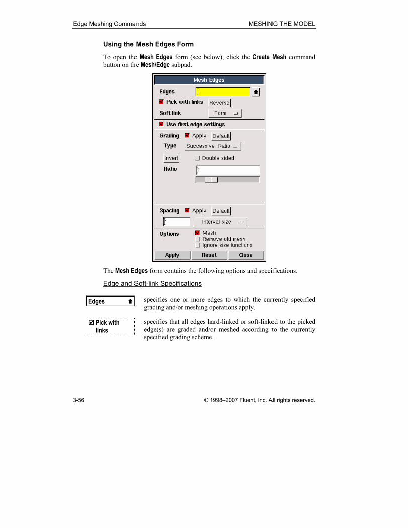
Using the Mesh Edges Form
To open the Mesh Edges form (see below), click the Create Mesh command
button on the Mesh/Edge subpad.
The Mesh Edges form contains the following options and specifications.
Edge and Soft-link Specifications
Edges � specifies one or more edges to which the currently specified
grading and/or meshing operations apply.
���� Pick with links
specifies that all edges hard-linked or soft-linked to the picked
edge(s) are graded and/or meshed according to the currently
specified grading scheme.
MESHING THE MODEL Edge Meshing Commands
© 1998–2007 Fluent, Inc. All rights reserved. 3-57
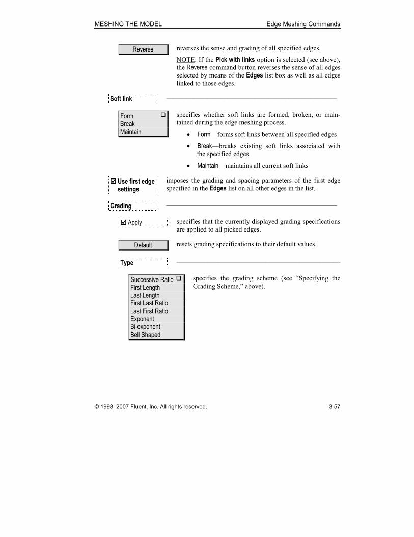
Reverse reverses the sense and grading of all specified edges.
NOTE: If the Pick with links option is selected (see above), the Reverse command button reverses the sense of all edges
selected by means of the Edges list box as well as all edges linked to those edges.
Soft link —————————————————————————
Form � Break Maintain
specifies whether soft links are formed, broken, or main-
tained during the edge meshing process.
• Form—forms soft links between all specified edges
• Break—breaks existing soft links associated with
the specified edges
• Maintain—maintains all current soft links
���� Use first edge settings
imposes the grading and spacing parameters of the first edge
specified in the Edges list on all other edges in the list.
Grading —————————————————————————
���� Apply specifies that the currently displayed grading specifications
are applied to all picked edges.
Default resets grading specifications to their default values.
Type ————————————————————————
Successive Ratio � First Length Last Length First Last Ratio Last First Ratio Exponent Bi-exponent Bell Shaped
specifies the grading scheme (see “Specifying the
Grading Scheme,” above).
Edge Meshing Commands MESHING THE MODEL
3-58 © 1998–2007 Fluent, Inc. All rights reserved.
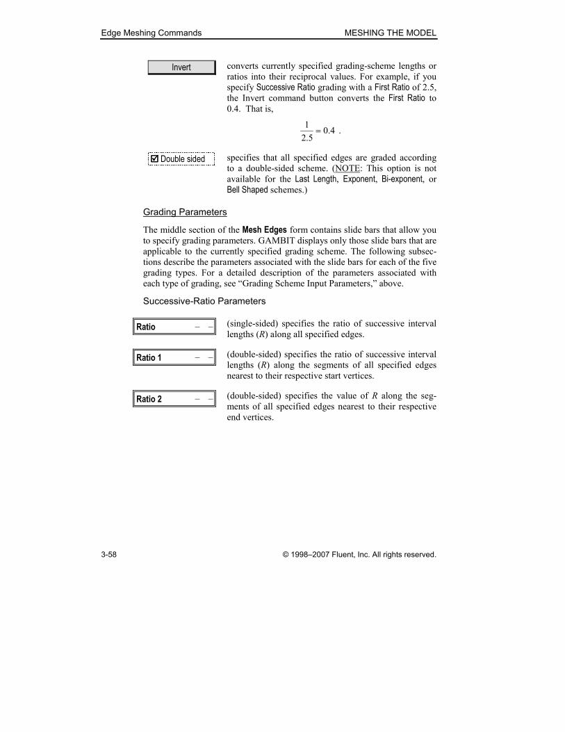
Invert converts currently specified grading-scheme lengths or
ratios into their reciprocal values. For example, if you
specify Successive Ratio grading with a First Ratio of 2.5, the Invert command button converts the First Ratio to 0.4. That is,
4.05.2
1= .
���� Double sided specifies that all specified edges are graded according
to a double-sided scheme. (NOTE: This option is not
available for the Last Length, Exponent, Bi-exponent, or Bell Shaped schemes.)
Grading Parameters
The middle section of the Mesh Edges form contains slide bars that allow you
to specify grading parameters. GAMBIT displays only those slide bars that are
applicable to the currently specified grading scheme. The following subsec-
tions describe the parameters associated with the slide bars for each of the five
grading types. For a detailed description of the parameters associated with
each type of grading, see “Grading Scheme Input Parameters,” above.
Successive-Ratio Parameters
Ratio –��������– (single-sided) specifies the ratio of successive interval
lengths (R) along all specified edges.
Ratio 1 –��������– (double-sided) specifies the ratio of successive interval
lengths (R) along the segments of all specified edges
nearest to their respective start vertices.
Ratio 2 –��������– (double-sided) specifies the value of R along the seg-
ments of all specified edges nearest to their respective
end vertices.
MESHING THE MODEL Edge Meshing Commands
© 1998–2007 Fluent, Inc. All rights reserved. 3-59
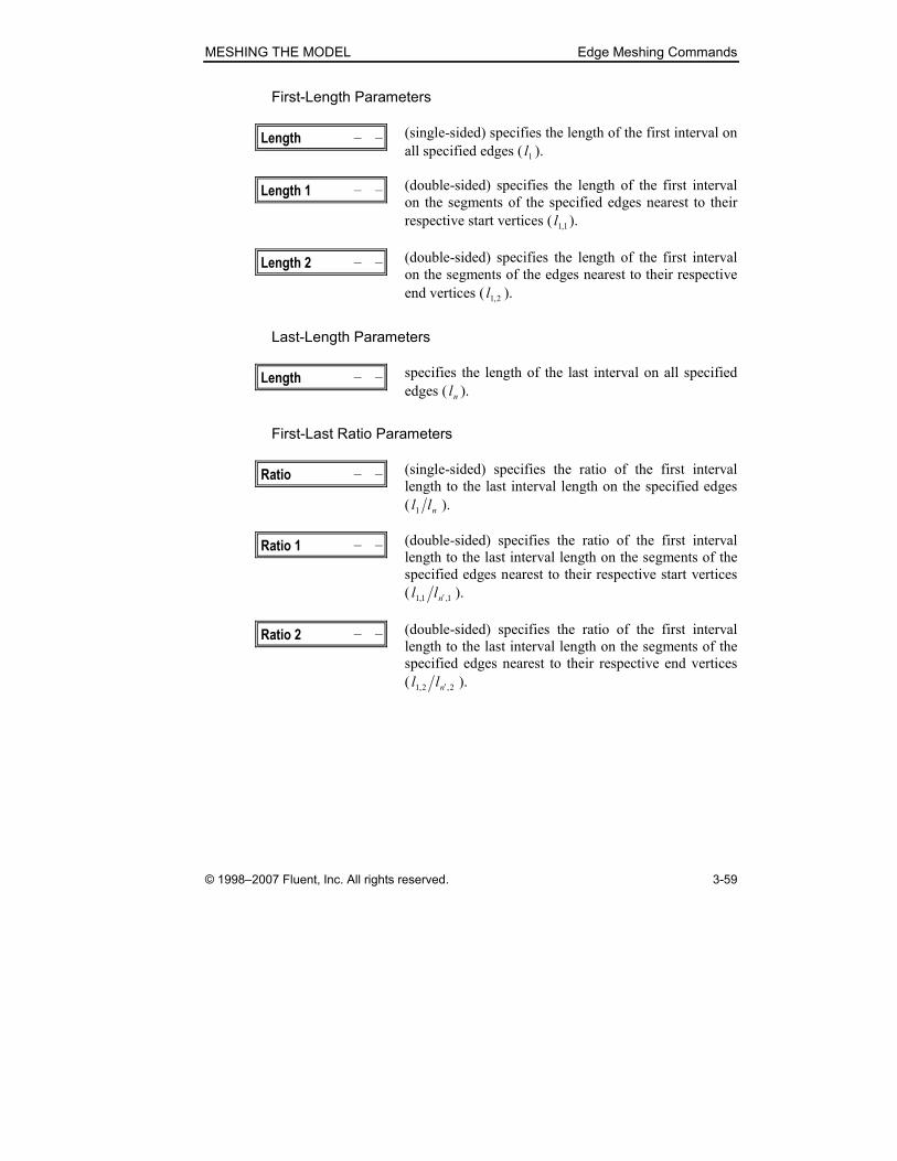
First-Length Parameters
Length –��������– (single-sided) specifies the length of the first interval on
all specified edges ( 1l ).
Length 1 –��������– (double-sided) specifies the length of the first interval
on the segments of the specified edges nearest to their
respective start vertices ( 1,1l ).
Length 2 –��������– (double-sided) specifies the length of the first interval
on the segments of the edges nearest to their respective
end vertices ( 2,1l ).
Last-Length Parameters
Length –��������– specifies the length of the last interval on all specified
edges ( nl ).
First-Last Ratio Parameters
Ratio –��������– (single-sided) specifies the ratio of the first interval
length to the last interval length on the specified edges
( nll1 ).
Ratio 1 –��������– (double-sided) specifies the ratio of the first interval
length to the last interval length on the segments of the
specified edges nearest to their respective start vertices
( 1,1,1 nll ′ ).
Ratio 2 –��������– (double-sided) specifies the ratio of the first interval
length to the last interval length on the segments of the
specified edges nearest to their respective end vertices
( 2,2,1 nll ′ ).

Edge Meshing Commands MESHING THE MODEL
3-60 © 1998–2007 Fluent, Inc. All rights reserved.
Last-First Ratio Parameters
Ratio –��������– (single-sided) specifies the ratio of the last interval
length to the first interval length on the specified edges
( 1lln ).
Ratio 1 –��������– (double-sided) specifies the ratio of the last interval
length to the first interval length on the segments of the
specified edges nearest to their respective start vertices
( 1,11, lln′ ).
Ratio 2 –��������– (double-sided) specifies the ratio of the last interval
length to the first interval length on the segments of the
specified edges nearest to their respective end vertices
( 2,12, lln′ ).
Exponent Parameter
Ratio –��������– specifies the input parameter, x, that determines the
ratio (R) of successive interval lengths for the Exponent grading scheme (see above).
Bi-exponent Parameter
Ratio –��������– specifies the input parameter, x, that determines the
ratio (R) of successive interval lengths for the Bi-exponent grading scheme (see above).
Bell Shaped Parameter
Ratio –��������– specifies the input parameter, x, that determines the
shape of the mesh node distribution for the Bell Shaped grading scheme.

MESHING THE MODEL Edge Meshing Commands
© 1998–2007 Fluent, Inc. All rights reserved. 3-61
Mesh Node Spacing Parameters
Spacing —————————————————————————
���� Apply specifies that the currently displayed spacing parameters
are applied to all specified edges.
Default resets mesh node spacing specifications to their default
values.
Interval size ���� Interval count Shortest edge (%)
specifies the method used to determine the total number of
mesh nodes on any edge. The three available methods are
as follows:
• Interval size—specifies the size of intervals (constant
ratio grading only)
• Interval count—specifies the number of intervals
along the edge
• Shortest edge (%)—specifies that the interval size
represents a percentage of the length of the shortest
edge in the list of specified edges
Value specifies a numerical value associated with the method
used to determine the total number of intervals on any
edge.
Grading and Meshing Options
Options —————————————————————————
���� Mesh specifies that the edges are to be meshed. If you do not
specify the Mesh option, GAMBIT grades but does not
create mesh nodes on the edges.
���� Remove old mesh
specifies that any existing mesh nodes and/or elements are
removed from the edges.
���� Ignore size functions
specifies that GAMBIT ignores any existing size-function
specifications that would otherwise affect the edge mesh.

Edge Meshing Commands MESHING THE MODEL
3-62 © 1998–2007 Fluent, Inc. All rights reserved.
3.2.2 Set Edge Element Type
The Set Edge Element Type operation (default set command for the
MESH.NODES.EDGE default variable) specifies the number of edge nodes
upon which all face and volume meshes are based.
The edge element type determines the number of edge mesh nodes corre-
sponding to face and volume elements in the model. There are two edge
element type options:
• 2 node
• 3 node
When you specify the 2 node option, GAMBIT creates meshes such that every
edge node constitutes one endpoint of an mesh edge element and, therefore,
one corner of a mesh face or volume element. When you specify the 3 node option, GAMBIT creates an additional mesh node in the center of each edge
mesh element. As a result, only two out of every three edge mesh nodes con-
stitute corners of mesh face or volume elements.
Figure 3-26 shows the effect of edge element type on quadrilateral face mesh
elements. In Figure 3-26(a), the edge element type is specified as 2 node, therefore, each edge mesh node constitutes one corner of a face element. In
Figure 3-26(b), the edge element type is specified as 3 node, therefore, only two out of every three edge mesh nodes constitute corners of face elements.

MESHING THE MODEL Edge Meshing Commands
© 1998–2007 Fluent, Inc. All rights reserved. 3-63
(a) 2 node (b) 3 node
Face mesh elements
Edges
Figure 3-26: 2 node and 3 node edge element types
The Effect on Face and Volume Element Types
When you change the edge element type specification, GAMBIT automati-
cally changes all corresponding face and volume element types. Likewise,
when you change the face or volume element types, GAMBIT automatically
changes the edge element type. The following table summarizes the general
correspondence between GAMBIT edge, face, and volume element types.
Edge Face Volume
Nodes Shape Nodes Shape Nodes
2 Triangle
Quadrilateral
3
4
Tetrahedral
Hexahedral
Wedge
Pyramid
4
8
6
5
3 Triangle
Quadrilateral
6
9
Hexahedral
Tetrahedral
Wedge
Pyramid
27
10
18
13

Edge Meshing Commands MESHING THE MODEL
3-64 © 1998–2007 Fluent, Inc. All rights reserved.
For a description of the face and volume element types listed above, see “Set
Face Element Type” and “Set Volume Element Type,” below.
Using the Set Edge Element Type Form
To open the Set Edge Element Type form (see below), click the Set Edge Element Type command button on the Mesh/Edge subpad.
The Set Edge Element Type form contains the following options.
���� 2 node specifies that the mesh is based on two-node edge mesh
elements.
���� 3 node specifies that the mesh is based on three-node edge mesh
elements.
MESHING THE MODEL Edge Meshing Commands
© 1998–2007 Fluent, Inc. All rights reserved. 3-65
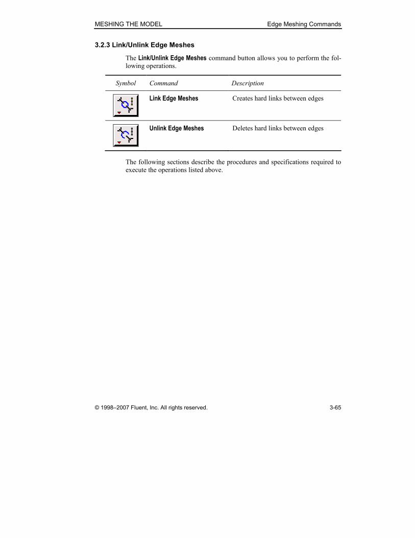
3.2.3 Link/Unlink Edge Meshes
The Link/Unlink Edge Meshes command button allows you to perform the fol-
lowing operations.
Symbol Command Description
Link Edge Meshes Creates hard links between edges
Unlink Edge Meshes Deletes hard links between edges
The following sections describe the procedures and specifications required to
execute the operations listed above.
Edge Meshing Commands MESHING THE MODEL
3-66 © 1998–2007 Fluent, Inc. All rights reserved.
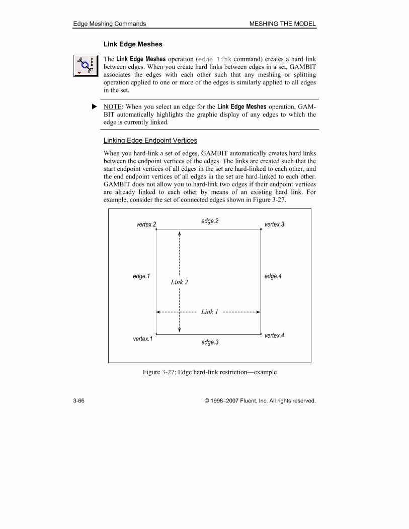
Link Edge Meshes
The Link Edge Meshes operation (edge link command) creates a hard link
between edges. When you create hard links between edges in a set, GAMBIT
associates the edges with each other such that any meshing or splitting
operation applied to one or more of the edges is similarly applied to all edges
in the set.
� NOTE: When you select an edge for the Link Edge Meshes operation, GAM-
BIT automatically highlights the graphic display of any edges to which the
edge is currently linked.
Linking Edge Endpoint Vertices
When you hard-link a set of edges, GAMBIT automatically creates hard links
between the endpoint vertices of the edges. The links are created such that the
start endpoint vertices of all edges in the set are hard-linked to each other, and
the end endpoint vertices of all edges in the set are hard-linked to each other.
GAMBIT does not allow you to hard-link two edges if their endpoint vertices
are already linked to each other by means of an existing hard link. For
example, consider the set of connected edges shown in Figure 3-27.
edge.1 edge.4
Link 1
edge.2
edge.3
Link 2
vertex.2 vertex.3
vertex.4vertex.1
Figure 3-27: Edge hard-link restriction—example
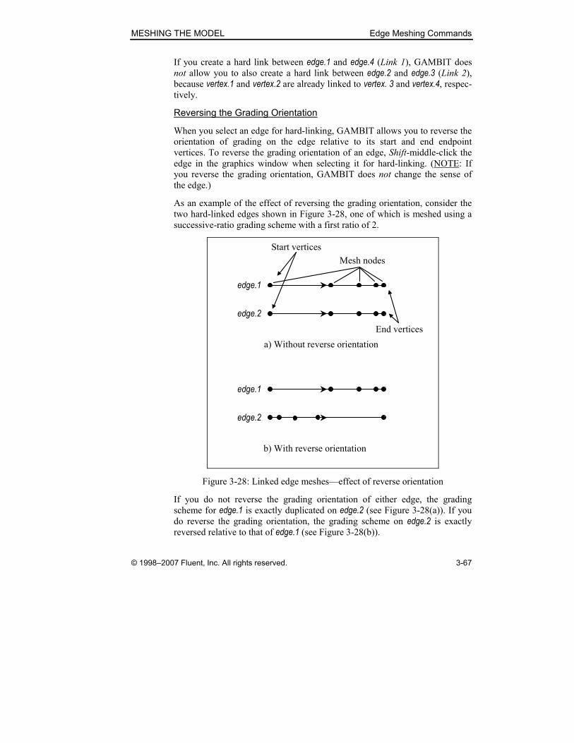
MESHING THE MODEL Edge Meshing Commands
© 1998–2007 Fluent, Inc. All rights reserved. 3-67
If you create a hard link between edge.1 and edge.4 (Link 1), GAMBIT does
not allow you to also create a hard link between edge.2 and edge.3 (Link 2), because vertex.1 and vertex.2 are already linked to vertex. 3 and vertex.4, respec-tively.
Reversing the Grading Orientation
When you select an edge for hard-linking, GAMBIT allows you to reverse the
orientation of grading on the edge relative to its start and end endpoint
vertices. To reverse the grading orientation of an edge, Shift-middle-click the
edge in the graphics window when selecting it for hard-linking. (NOTE: If
you reverse the grading orientation, GAMBIT does not change the sense of
the edge.)
As an example of the effect of reversing the grading orientation, consider the
two hard-linked edges shown in Figure 3-28, one of which is meshed using a
successive-ratio grading scheme with a first ratio of 2.
edge.1
Mesh nodes
a) Without reverse orientation
edge.2
edge.1
b) With reverse orientation
edge.2
Start vertices
End vertices
Figure 3-28: Linked edge meshes—effect of reverse orientation
If you do not reverse the grading orientation of either edge, the grading
scheme for edge.1 is exactly duplicated on edge.2 (see Figure 3-28(a)). If you do reverse the grading orientation, the grading scheme on edge.2 is exactly reversed relative to that of edge.1 (see Figure 3-28(b)).

Edge Meshing Commands MESHING THE MODEL
3-68 © 1998–2007 Fluent, Inc. All rights reserved.
Specifying the Periodic Option
The Link Edge Meshes command includes a Periodic option that allows you to specify that the edges are periodically linked. Periodically linked edges are
constrained such that they must behave identically to each other with respect
to any virtual edge-split and vertex-move operations.
As an example of the effect of periodic linking, consider the square, planar
face shown in Figure 3-29, two edges (edge.1 and edge.3) of which are hard-linked to each other.
(a) (b)
edge.1 edge.3
v_vertex.5 v_vertex.6Split point
v_edge.5 v_edge.7
v_edge.8v_edge.6
Linked edges
Figure 3-29: Virtual splitting of two hard linked edges
If you perform a virtual split of edge.1 at the split point shown in Figure 3-29(a), GAMBIT splits both edges to create the geometric entities shown in
Figure 3-29(b). (NOTE: In this example, the hard link was created such that
the grading orientations of edge.1 and edge.3 point in the same direction,
therefore v_edge.5 and v_edge.7 are equal in length. If the grading orientations had opposed each other when the link was created, v_edge.8 would be equal in length to v_edge.5, and v_edge.7 would be equal in length to v_edge.6).
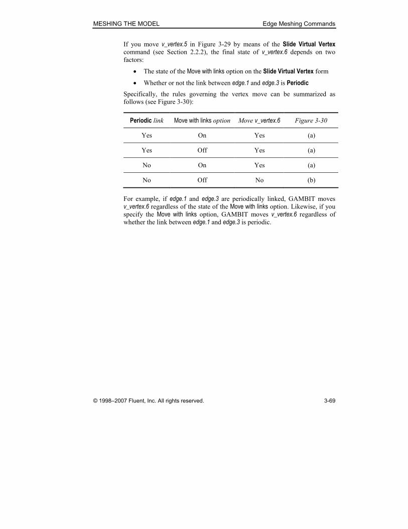
MESHING THE MODEL Edge Meshing Commands
© 1998–2007 Fluent, Inc. All rights reserved. 3-69
If you move v_vertex.5 in Figure 3-29 by means of the Slide Virtual Vertex command (see Section 2.2.2), the final state of v_vertex.6 depends on two factors:
• The state of the Move with links option on the Slide Virtual Vertex form
• Whether or not the link between edge.1 and edge.3 is Periodic
Specifically, the rules governing the vertex move can be summarized as
follows (see Figure 3-30):
Periodic link Move with links option Move v_vertex.6 Figure 3-30
Yes On Yes (a)
Yes Off Yes (a)
No On Yes (a)
No Off No (b)
For example, if edge.1 and edge.3 are periodically linked, GAMBIT moves
v_vertex.6 regardless of the state of the Move with links option. Likewise, if you specify the Move with links option, GAMBIT moves v_vertex.6 regardless of whether the link between edge.1 and edge.3 is periodic.

Edge Meshing Commands MESHING THE MODEL
3-70 © 1998–2007 Fluent, Inc. All rights reserved.
(b) v_vertex.6 unmoved
v_vertex.5
v_vertex.6
(a) v_vertex.6 moved
v_vertex.5 v_vertex.6
Figure 3-30: v_vertex.6 move states—Periodic and Move with links options
Using the Link Edge Meshes Form
To open the Link Edge Meshes form (see below), click the Link command
button on the Mesh/Edge subpad.
The Link Edge Meshes form contains the following specifications.
Edges � specifies the edges to be hard-linked.
���� Periodic specifies that the edges are to be periodically linked.
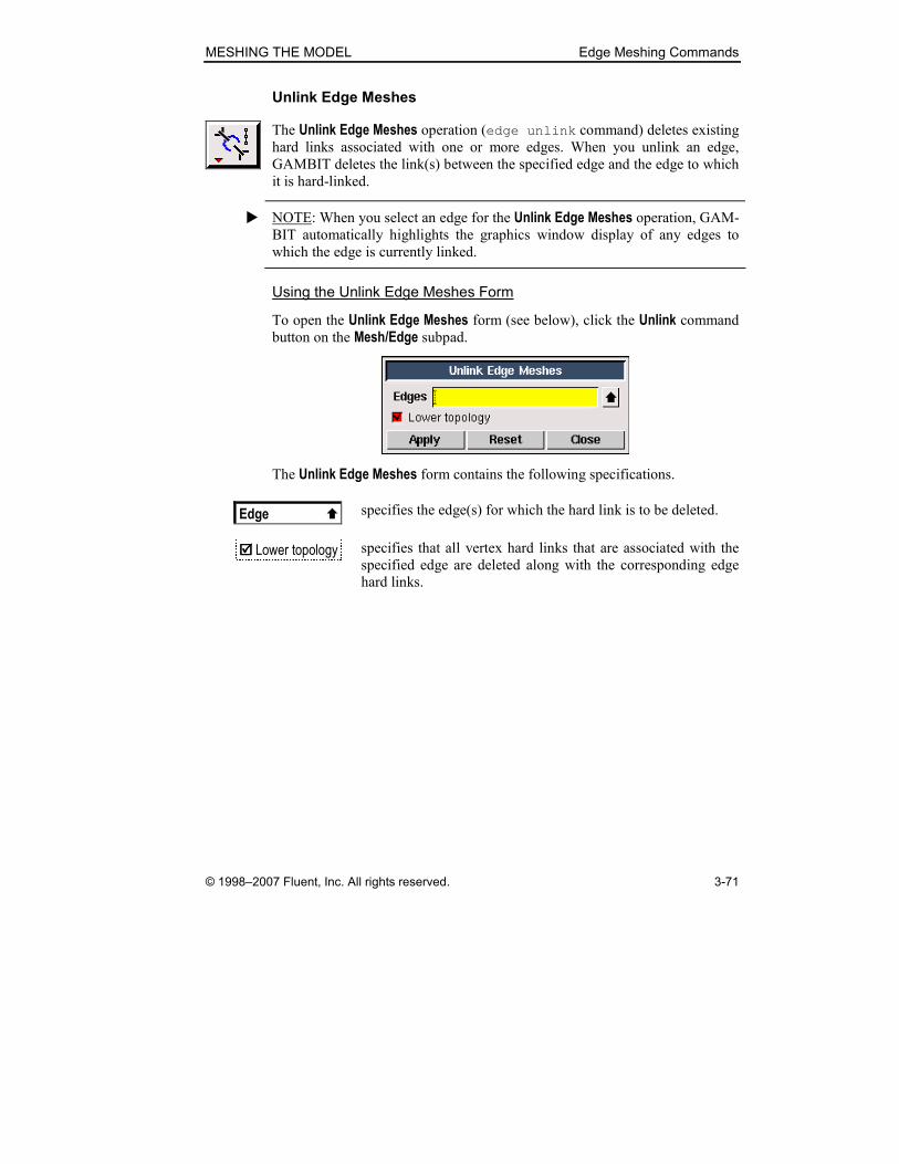
MESHING THE MODEL Edge Meshing Commands
© 1998–2007 Fluent, Inc. All rights reserved. 3-71
Unlink Edge Meshes
The Unlink Edge Meshes operation (edge unlink command) deletes existing
hard links associated with one or more edges. When you unlink an edge,
GAMBIT deletes the link(s) between the specified edge and the edge to which
it is hard-linked.
� NOTE: When you select an edge for the Unlink Edge Meshes operation, GAM-
BIT automatically highlights the graphics window display of any edges to
which the edge is currently linked.
Using the Unlink Edge Meshes Form
To open the Unlink Edge Meshes form (see below), click the Unlink command
button on the Mesh/Edge subpad.
The Unlink Edge Meshes form contains the following specifications.
Edge � specifies the edge(s) for which the hard link is to be deleted.
���� Lower topology specifies that all vertex hard links that are associated with the
specified edge are deleted along with the corresponding edge
hard links.

Edge Meshing Commands MESHING THE MODEL
3-72 © 1998–2007 Fluent, Inc. All rights reserved.
3.2.4 Split Meshed Edge
The Split Meshed Edge operation (edge split meshnode command) splits
a real or virtual edge at a mesh node.
When you split an edge at a mesh node, GAMBIT splits the edge into two
virtual edges that share a common virtual endpoint vertex. The common ver-
tex is located at the position of the specified node.
When you specify the edge to be split, GAMBIT displays its existing mesh in
the graphics window. To specify the exact mesh node at which the edge is to
be split, either pick the node in the graphics window (using the mouse) or
select the mesh node by means of the Mesh Node pick-list form.
Using the Split Meshed Edge Form
To open the Split Meshed Edge form (see below), click the Split Edge com-
mand button on the Mesh/Edge subpad.
The Split Meshed Edge form contains the following specifications.
Edge � specifies the edge to be split.
Split With —————————————————————————
Node specifies the node at which the edge is to be split.

MESHING THE MODEL Edge Meshing Commands
© 1998–2007 Fluent, Inc. All rights reserved. 3-73
3.2.5 Summarize Edge Mesh
The Summarize Edge Mesh operation (edge msummarize command) dis-
plays edge mesh information in the Transcript window and allows you to highlight specific mesh nodes and/or edge mesh elements in the graphics
window. The command requires three input parameters:
• Edge for which the mesh is to be summarized
• Type of component (elements or nodes) to be summarized
• Specific components to be included in the summary
Specifying the Component Type
To summarize edge mesh information in the Transcript window, you must
specify the type of mesh components to be included in the summary. Each
edge mesh includes two component types:
• Elements
• Nodes
The type of edge mesh summary information displayed in the Transcript window depends on the component type (see “Edge Mesh Summary
Information,” below).
Selecting Specific Components
GAMBIT provides two methods for selecting specific components (elements
or nodes) to be included in the edge mesh summary:
• Picking the components in the graphics window
• Selecting the components by means of a pick list
In most cases, it is preferable to pick the components in the graphics window,
rather than selecting them by means of a pick list, because the component
labels (element or node numbers) are not known prior to component selection.
To pick the components in the graphics window:
1. Select the appropriate Component option (Elements or Nodes).
2. Click (to activate) the appropriate (Elements or Nodes) pick-list field.
3. Shift-left-click in the graphics window to select each element or node
to be included in the summary.

Edge Meshing Commands MESHING THE MODEL
3-74 © 1998–2007 Fluent, Inc. All rights reserved.
To select the components by means of a pick list:
1. Select the appropriate Component option (Elements or Nodes).
2. Click the appropriate (Elements or Nodes) pick-list button to open the Mesh Edge List (Multiple) or Mesh Node List (Multiple) form.
3. On the Mesh Edge List (Multiple) or Mesh Node List (Multiple) form,
click the All–> pushbutton to populate the list with all elements or
nodes associated with the specified edge.
4. In the Mesh Edge List (Multiple) or Mesh Node List (Multiple) list, select (highlight) the elements or nodes to be excluded from the summary.
5. Click the <– – – pushbutton to remove the selected (highlighted) ele-
ments or nodes from the list.
� NOTE: The Mesh Edge List (Multiple) and Mesh Node List (Multiple) forms do
not include the Available list field that is included on most pick-list forms
because of the number of items that might need to be included in the list field.
A fully meshed model can contain tens of thousands of edge mesh elements or
nodes, each of which constitutes an Available component. If the Mesh Edge List (Multiple) or Mesh Node List (Multiple) form included an Available list field, GAMBIT would need to compile the Available list before opening the form,
thereby delaying the appearance of the form on the GUI.
When you specify any component (element or node) to be included in the
edge mesh summary, GAMBIT highlights the component in the graphics
window. If you select the Element labels and/or Node labels options, GAMBIT
also displays the element and/or node numbers associated with the specified
components (see Figure 3-31).
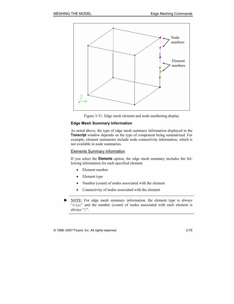
MESHING THE MODEL Edge Meshing Commands
© 1998–2007 Fluent, Inc. All rights reserved. 3-75
Node
numbers
Element
numbers
Figure 3-31: Edge mesh element and node numbering display
Edge Mesh Summary Information
As noted above, the type of edge mesh summary information displayed in the
Transcript window depends on the type of component being summarized. For
example, element summaries include node connectivity information, which is
not available in node summaries.
Elements Summary Information
If you select the Elements option, the edge mesh summary includes the fol-
lowing information for each specified element.
• Element number
• Element type
• Number (count) of nodes associated with the element
• Connectivity of nodes associated with the element
� NOTE: For edge mesh summary information, the element type is always
“edge” and the number (count) of nodes associated with each element is
always “2”.

Edge Meshing Commands MESHING THE MODEL
3-76 © 1998–2007 Fluent, Inc. All rights reserved.
For example, if you select an Elements summary for the edge and highlighted
elements shown in Figure 3-31, above, GAMBIT displays the following infor-
mation in the Transcript window.
Total nodes: 6
Total elements: 3
Element Type Count Connectivity
----------- --------- -------------- ----------------------
1 edge 2: 1 3
3 edge 2: 4 5
4 edge 2: 5 6
In this case, the summary indicates that element 3 is an edge mesh element
connected to nodes 4 and 5.
Nodes Summary Information
If you select the Nodes option, the edge mesh summary includes the following
information for each specified node.
• Node number
• Coordinates (x, y, z) of the node
• Geometric entity (“owner”) associated with the node
For example, if you select a Nodes summary for the edge and highlighted
nodes shown in Figure 3-31, above, GAMBIT displays the following informa-
tion in the Transcript window.
Total nodes: 6
Total elements: 3
Coordinate System: c_sys.1
Node x y z Owner
----------- --------- ---------- --------- -------------
1 5.0000 5.0000 -5.0000 vertex.4
3 5.0000 3.0000 -5.0000 edge.3
4 5.0000 1.0000 -5.0000 edge.3
5 5.0000 -1.0000 -5.0000 edge.3
6 5.0000 3.0000 -5.0000 edge.3
In this case, the summary indicates that node 1 is located at the position (5, 5,
-5) and is associated with (“owned by”) vertex.4.

MESHING THE MODEL Edge Meshing Commands
© 1998–2007 Fluent, Inc. All rights reserved. 3-77
Using the Summarize Edge Mesh Form
To open the Summarize Edge Mesh form (see below), click the Summarize command button on the Mesh/Edge subpad.
The Summarize Edge Mesh form contains the following options and specifica-
tions.
Edge � specifies the edge for which summary information is to be
displayed.
Component —————————————————————————
���� Elements displays summary information for specified elements.
All � Pick
specifies whether the mesh summary information
includes all elements or only selected elements.
Pick � specifies the elements for which mesh summary
information is to be displayed.
���� Element labels displays labels (numbers) in the graphics window for all
specified elements.
���� Node labels displays labels (numbers) in the graphics window for all
nodes associated with the specified elements.
���� Nodes displays summary information for specified nodes.
All � Pick
specifies whether the edge mesh summary information
includes all nodes or only selected nodes.
Edge Meshing Commands MESHING THE MODEL
3-78 © 1998–2007 Fluent, Inc. All rights reserved.
Pick � specifies the nodes for which edge mesh summary
information is to be displayed.
���� Node labels displays labels (numbers) in the graphics window for all
specified nodes.
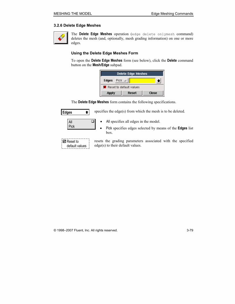
MESHING THE MODEL Edge Meshing Commands
© 1998–2007 Fluent, Inc. All rights reserved. 3-79
3.2.6 Delete Edge Meshes
The Delete Edge Meshes operation (edge delete onlymesh command)
deletes the mesh (and, optionally, mesh grading information) on one or more
edges.
Using the Delete Edge Meshes Form
To open the Delete Edge Meshes form (see below), click the Delete command
button on the Mesh/Edge subpad.
The Delete Edge Meshes form contains the following specifications.
Edges � specifies the edge(s) from which the mesh is to be deleted.
All � Pick
• All specifies all edges in the model.
• Pick specifies edges selected by means of the Edges list box.
���� Reset to default values
resets the grading parameters associated with the specified
edge(s) to their default values.

Face Meshing Commands MESHING THE MODEL
3-80 © 1998–2007 Fluent, Inc. All rights reserved.
3.3 Face Meshing Commands
The following commands are available on the Mesh/Face subpad.
Symbol Command Description
Mesh Faces Creates mesh nodes on faces
Move Face Nodes Split Quad Meshes
Adjusts mesh node positions on a
face; splits quadrilateral face mesh
elements into triangular elements
Smooth Face Meshes Adjusts face mesh node positions to
improve uniformity of node spacing
Set Face Vertex Type Specifies the characteristics of a face
mesh in the vicinity of a corner
Set Face Element Type Specifies face element types used
throughout the model
Link Face Meshes Unlink Face Meshes
Creates or removes mesh hard links
between faces
Modify Meshed Face Split Meshed Face
Converts mesh edges to topological
equivalents; splits faces along
boundaries defined by mesh node
locations
Summarize Face Mesh Check Face Meshes
Displays mesh information in the
graphics window; summarizes face
mesh quality information
Delete Face Meshes Deletes existing mesh nodes and/or
elements from faces
MESHING THE MODEL Face Meshing Commands
© 1998–2007 Fluent, Inc. All rights reserved. 3-81
3.3.1 Mesh Faces
The Mesh Faces operation (face mesh and face modify commands)
creates the mesh for one or more faces in the model. When you mesh a face,
GAMBIT creates mesh nodes on the face according to the currently specified
meshing parameters.
The Mesh Faces operation requires the following input parameters:
• Face(s) to be meshed
• Meshing scheme
• Mesh node spacing
• Face meshing options
Specifying the Faces
GAMBIT allows you to specify any face for a meshing operation; however,
the shape and topological characteristics of the face, as well as the vertex
types associated with the face, determine the type(s) of mesh scheme(s) that
can be applied to the face.
Specifying the Meshing Scheme
To specify the face-meshing scheme, you must specify the following para-
meters:
• Elements
• Type
• Smoother (Map meshes only)
The Elements parameter defines the shape(s) of the elements that are used to
mesh the face. The Type parameter defines the pattern of mesh elements on
the face. The Smoother specification determines the type of smoothing algo-
rithm (if any) used to smooth a mapped mesh during the meshing operation.
The following sections describe the parameters listed above and their effects
on the overall face mesh.
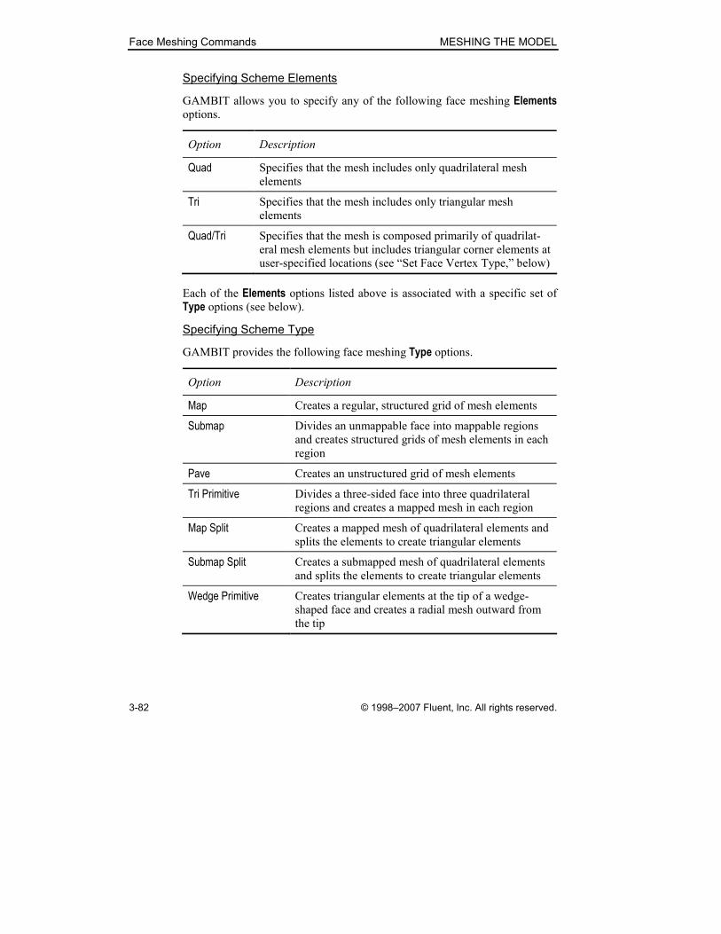
Face Meshing Commands MESHING THE MODEL
3-82 © 1998–2007 Fluent, Inc. All rights reserved.
Specifying Scheme Elements
GAMBIT allows you to specify any of the following face meshing Elements options.
Option Description
Quad Specifies that the mesh includes only quadrilateral mesh
elements
Tri Specifies that the mesh includes only triangular mesh
elements
Quad/Tri Specifies that the mesh is composed primarily of quadrilat-
eral mesh elements but includes triangular corner elements at
user-specified locations (see “Set Face Vertex Type,” below)
Each of the Elements options listed above is associated with a specific set of Type options (see below).
Specifying Scheme Type
GAMBIT provides the following face meshing Type options.
Option Description
Map Creates a regular, structured grid of mesh elements
Submap Divides an unmappable face into mappable regions
and creates structured grids of mesh elements in each
region
Pave Creates an unstructured grid of mesh elements
Tri Primitive Divides a three-sided face into three quadrilateral
regions and creates a mapped mesh in each region
Map Split Creates a mapped mesh of quadrilateral elements and
splits the elements to create triangular elements
Submap Split Creates a submapped mesh of quadrilateral elements
and splits the elements to create triangular elements
Wedge Primitive Creates triangular elements at the tip of a wedge-
shaped face and creates a radial mesh outward from
the tip
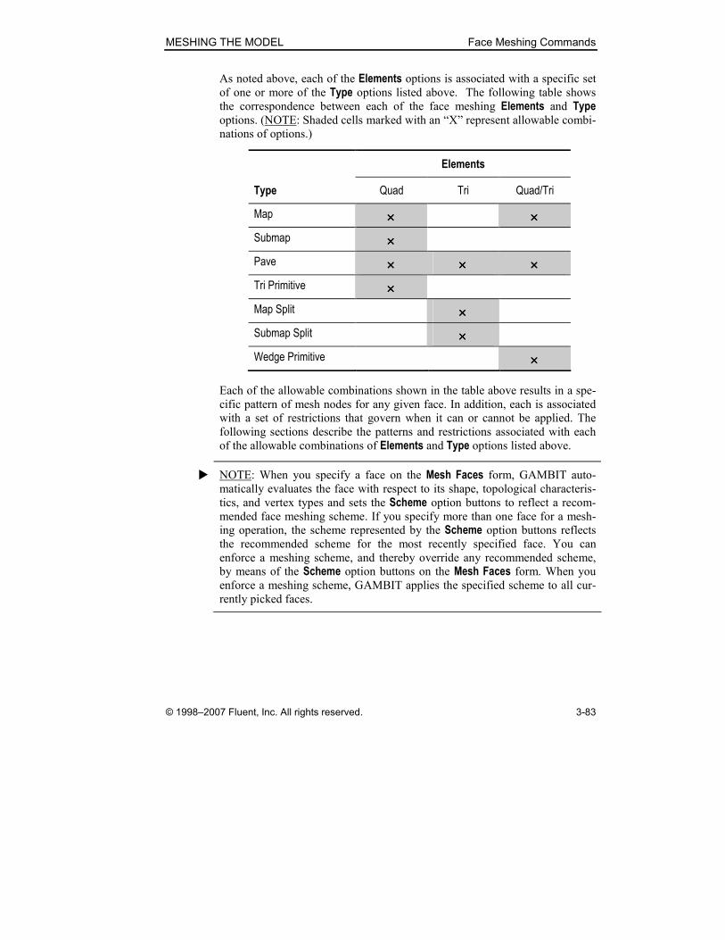
MESHING THE MODEL Face Meshing Commands
© 1998–2007 Fluent, Inc. All rights reserved. 3-83
As noted above, each of the Elements options is associated with a specific set of one or more of the Type options listed above. The following table shows the correspondence between each of the face meshing Elements and Type options. (NOTE: Shaded cells marked with an “X” represent allowable combi-
nations of options.)
Elements
Type Quad Tri Quad/Tri
Map ×××× ××××
Submap ××××
Pave ×××× ×××× ××××
Tri Primitive ××××
Map Split ××××
Submap Split ××××
Wedge Primitive ××××
Each of the allowable combinations shown in the table above results in a spe-
cific pattern of mesh nodes for any given face. In addition, each is associated
with a set of restrictions that govern when it can or cannot be applied. The
following sections describe the patterns and restrictions associated with each
of the allowable combinations of Elements and Type options listed above.
� NOTE: When you specify a face on the Mesh Faces form, GAMBIT auto-
matically evaluates the face with respect to its shape, topological characteris-
tics, and vertex types and sets the Scheme option buttons to reflect a recom-
mended face meshing scheme. If you specify more than one face for a mesh-
ing operation, the scheme represented by the Scheme option buttons reflects the recommended scheme for the most recently specified face. You can
enforce a meshing scheme, and thereby override any recommended scheme,
by means of the Scheme option buttons on the Mesh Faces form. When you
enforce a meshing scheme, GAMBIT applies the specified scheme to all cur-
rently picked faces.
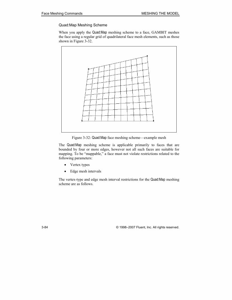
Face Meshing Commands MESHING THE MODEL
3-84 © 1998–2007 Fluent, Inc. All rights reserved.
Quad:Map Meshing Scheme
When you apply the Quad:Map meshing scheme to a face, GAMBIT meshes
the face using a regular grid of quadrilateral face mesh elements, such as those
shown in Figure 3-32.
Figure 3-32: Quad:Map face meshing scheme—example mesh
The Quad:Map meshing scheme is applicable primarily to faces that are
bounded by four or more edges, however not all such faces are suitable for
mapping. To be “mappable,” a face must not violate restrictions related to the
following parameters:
• Vertex types
• Edge mesh intervals
The vertex-type and edge mesh interval restrictions for the Quad:Map meshing
scheme are as follows.
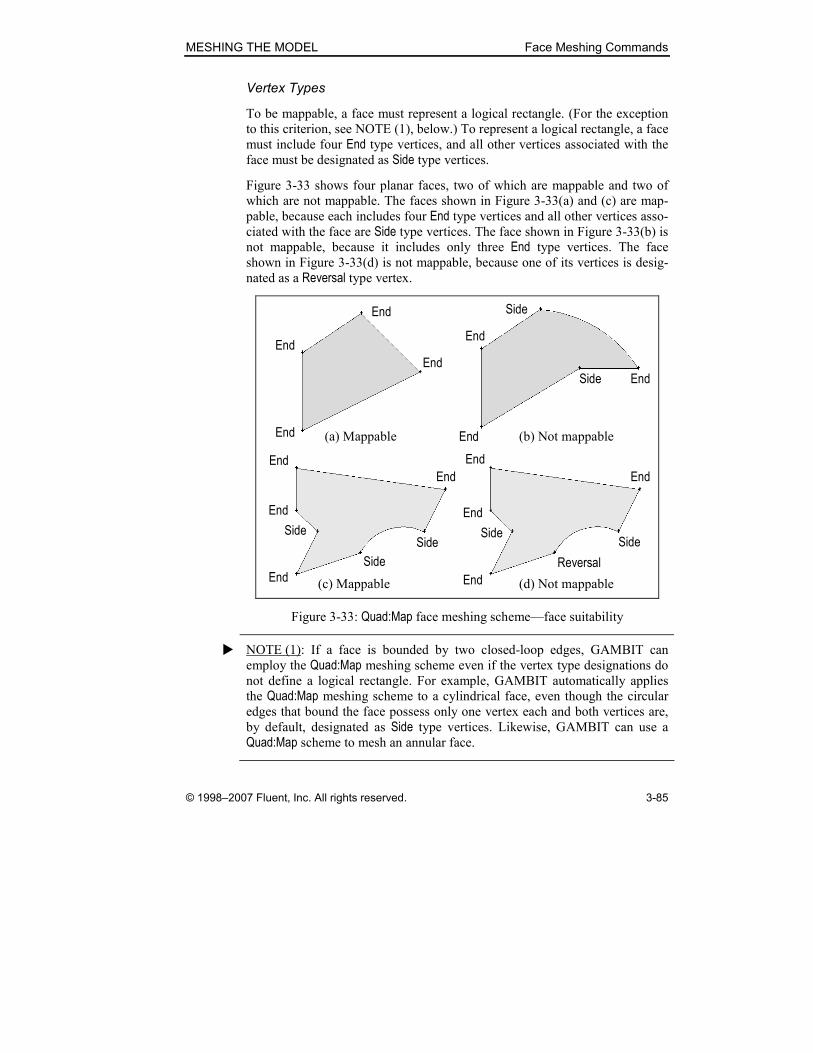
MESHING THE MODEL Face Meshing Commands
© 1998–2007 Fluent, Inc. All rights reserved. 3-85
Vertex Types
To be mappable, a face must represent a logical rectangle. (For the exception
to this criterion, see NOTE (1), below.) To represent a logical rectangle, a face
must include four End type vertices, and all other vertices associated with the face must be designated as Side type vertices.
Figure 3-33 shows four planar faces, two of which are mappable and two of
which are not mappable. The faces shown in Figure 3-33(a) and (c) are map-
pable, because each includes four End type vertices and all other vertices asso-ciated with the face are Side type vertices. The face shown in Figure 3-33(b) is not mappable, because it includes only three End type vertices. The face shown in Figure 3-33(d) is not mappable, because one of its vertices is desig-
nated as a Reversal type vertex.
End
End
End
End
(a) Mappable
End
End
Side
EndSide
(b) Not mappable
End
End
End
End
Side
Side
Side
End
End
End
End
Side
Reversal
Side
(c) Mappable (d) Not mappable
Figure 3-33: Quad:Map face meshing scheme—face suitability
� NOTE (1): If a face is bounded by two closed-loop edges, GAMBIT can
employ the Quad:Map meshing scheme even if the vertex type designations do
not define a logical rectangle. For example, GAMBIT automatically applies
the Quad:Map meshing scheme to a cylindrical face, even though the circular
edges that bound the face possess only one vertex each and both vertices are,
by default, designated as Side type vertices. Likewise, GAMBIT can use a
Quad:Map scheme to mesh an annular face.
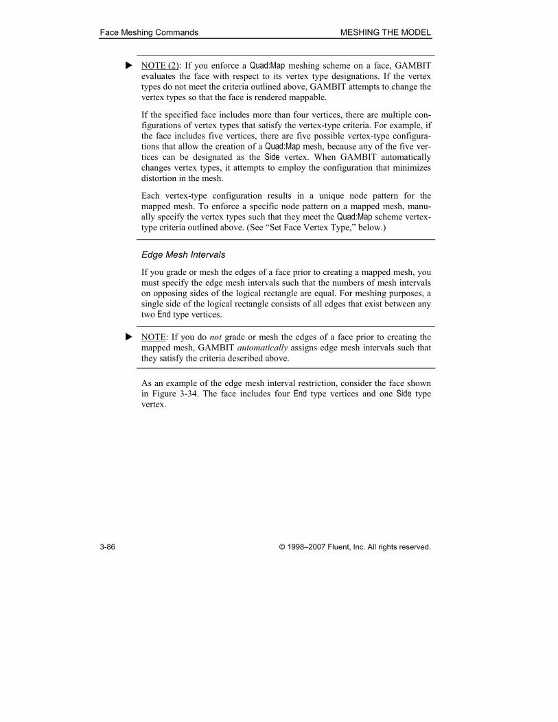
Face Meshing Commands MESHING THE MODEL
3-86 © 1998–2007 Fluent, Inc. All rights reserved.
� NOTE (2): If you enforce a Quad:Map meshing scheme on a face, GAMBIT
evaluates the face with respect to its vertex type designations. If the vertex
types do not meet the criteria outlined above, GAMBIT attempts to change the
vertex types so that the face is rendered mappable.
If the specified face includes more than four vertices, there are multiple con-
figurations of vertex types that satisfy the vertex-type criteria. For example, if
the face includes five vertices, there are five possible vertex-type configura-
tions that allow the creation of a Quad:Map mesh, because any of the five ver-
tices can be designated as the Side vertex. When GAMBIT automatically
changes vertex types, it attempts to employ the configuration that minimizes
distortion in the mesh.
Each vertex-type configuration results in a unique node pattern for the
mapped mesh. To enforce a specific node pattern on a mapped mesh, manu-
ally specify the vertex types such that they meet the Quad:Map scheme vertex-
type criteria outlined above. (See “Set Face Vertex Type,” below.)
Edge Mesh Intervals
If you grade or mesh the edges of a face prior to creating a mapped mesh, you
must specify the edge mesh intervals such that the numbers of mesh intervals
on opposing sides of the logical rectangle are equal. For meshing purposes, a
single side of the logical rectangle consists of all edges that exist between any
two End type vertices.
� NOTE: If you do not grade or mesh the edges of a face prior to creating the
mapped mesh, GAMBIT automatically assigns edge mesh intervals such that
they satisfy the criteria described above.
As an example of the edge mesh interval restriction, consider the face shown
in Figure 3-34. The face includes four End type vertices and one Side type vertex.
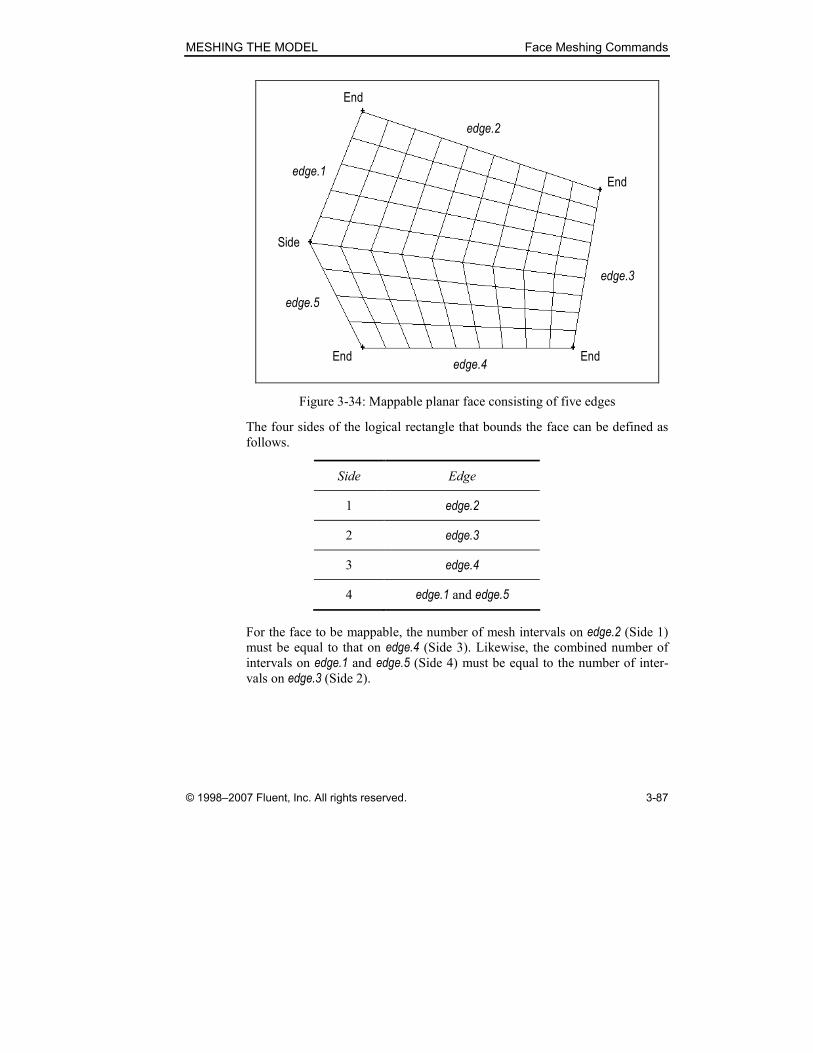
MESHING THE MODEL Face Meshing Commands
© 1998–2007 Fluent, Inc. All rights reserved. 3-87
End
Side
End End
Endedge.1
edge.5
edge.4
edge.3
edge.2
Figure 3-34: Mappable planar face consisting of five edges
The four sides of the logical rectangle that bounds the face can be defined as
follows.
Side Edge
1 edge.2
2 edge.3
3 edge.4
4 edge.1 and edge.5
For the face to be mappable, the number of mesh intervals on edge.2 (Side 1) must be equal to that on edge.4 (Side 3). Likewise, the combined number of
intervals on edge.1 and edge.5 (Side 4) must be equal to the number of inter-
vals on edge.3 (Side 2).
Face Meshing Commands MESHING THE MODEL
3-88 © 1998–2007 Fluent, Inc. All rights reserved.
� NOTE (1): If you grade or mesh one or more edges of a face and apply a
Quad:Map meshing scheme to the face, GAMBIT automatically meshes the
remaining edges such that the numbers of intervals on opposing sides of the
face satisfy the criteria outlined above. For example, if you grade or mesh
edge.3 in Figure 3-34 such that it contains 10 intervals, GAMBIT meshes
edge.1 and edge.5 such that they include a combined total of 10 intervals.
� NOTE (2): GAMBIT does not include the edge mesh interval restriction when
evaluating a face with respect to a recommended meshing scheme. As a result,
GAMBIT may recommend a Quad:Map meshing scheme for a face that is
mappable with respect to its vertex-type configuration but which cannot be
mapped, because it violates the edge mesh interval restriction.
� NOTE (3): If you create a mesh link between two edges that constitute
opposing sides of a logical rectangle, the edges automatically satisfy the edge
mesh interval restriction described above.
� NOTE (4): If you mesh a face using the Quad:Map meshing scheme, you can
smooth the mesh during its creation by means of the Smoother options (see “Specifying Scheme Smoother Algorithm,” below).
� NOTE (5): When you apply the Quad:Map scheme to a face bounded by two
closed loops (for example, a cylindrical or annular face), GAMBIT allows you
to specify the number of mesh intervals between the loops (see “Specifying
Projection Intervals,” below).
MESHING THE MODEL Face Meshing Commands
© 1998–2007 Fluent, Inc. All rights reserved. 3-89
Quad:Submap Meshing Scheme
When you apply the Quad:Submap meshing scheme to a face, GAMBIT
divides the face into one or more mappable regions and creates a mapped
mesh in each region. Like the Quad:Map meshing scheme, the Quad:Submap meshing scheme is subject to restrictions related to vertex types and edge
mesh intervals. The vertex-type and edge mesh interval restrictions for the
Quad:Submap meshing scheme are as follows.
Vertex Types
To constitute a submappable face, a face must possess only End, Side, Corner,
and Reversal vertices. In addition, the total number of End vertices, EN , must
satisfy the following equation:
RCE NNN 24 ++=
where CN and RN are the total numbers of Corner and Reversal type vertices,
respectively, on the face. That is, for every Corner type vertex, the face must
possess an additional End vertex, and for every Reversal vertex, the face must
possess two additional End vertices.
The shape of the mesh generated by means of the Quad:Submap face meshing
scheme depends on the type and arrangement of vertex types on the face. As
an example of the effect of vertex types, consider the faces shown in Figure
3-35 and Figure 3-36, each of which consists of an identical planar L-shaped
face, one corner of which is truncated at an angle.
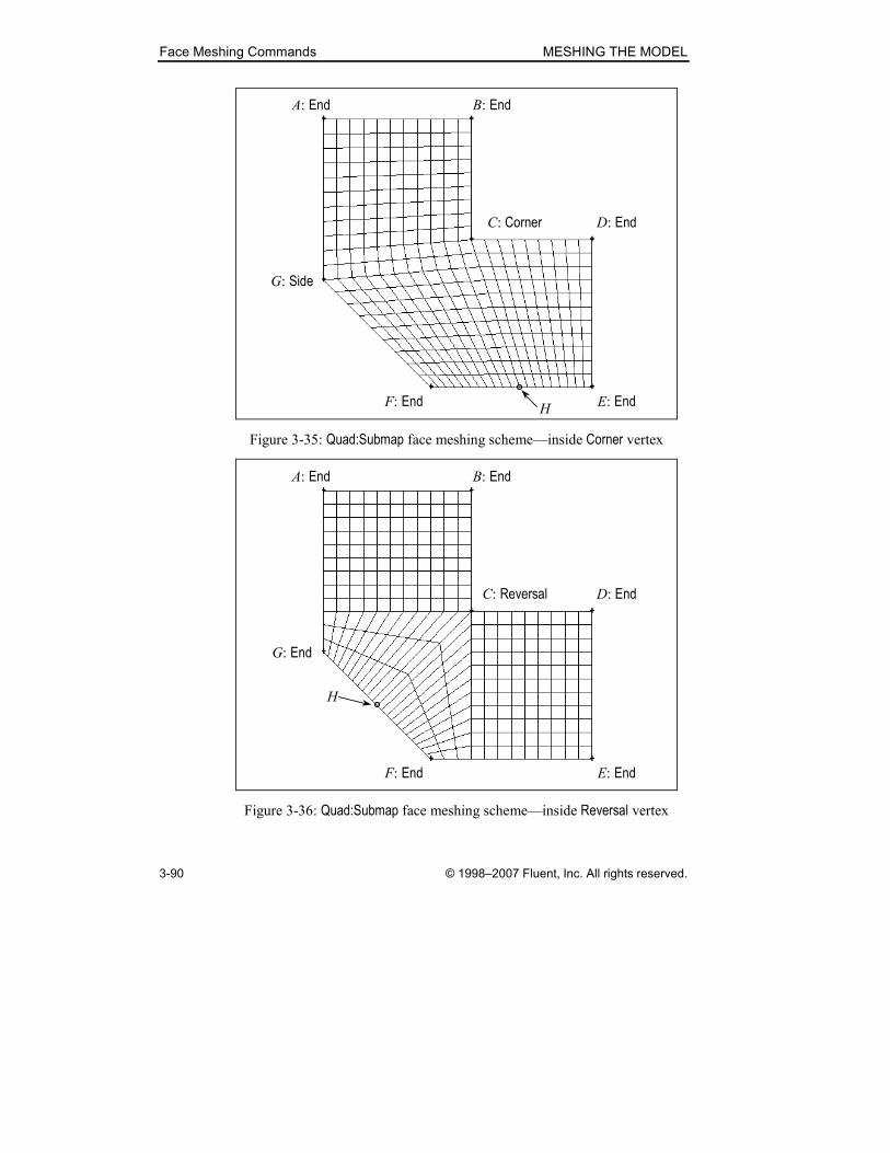
Face Meshing Commands MESHING THE MODEL
3-90 © 1998–2007 Fluent, Inc. All rights reserved.
A: End
C: Corner
G: Side
F: End E: End
D: End
B: End
H
Figure 3-35: Quad:Submap face meshing scheme—inside Corner vertex
A: End
C: Reversal
G: End
F: End E: End
D: End
B: End
H
Figure 3-36: Quad:Submap face meshing scheme—inside Reversal vertex

MESHING THE MODEL Face Meshing Commands
© 1998–2007 Fluent, Inc. All rights reserved. 3-91
In Figure 3-35, the inside corner vertex I is designated as a Corner vertex, therefore, in order to be submappable, the face must possess five End type ver-tices (A, B, D, E, and F). The Quad:Submap meshing scheme divides the face
into the following two mapped regions:
• A, B, C, H, F, G
• C, D, E, H
In Figure 3-36, the inside corner vertex I is designated as a Reversal vertex, therefore, in order to be submappable, the face must possess six End type vertices (A, B, D, E, F, and G). In this case, the Quad:Submap meshing scheme
divides the face into the following two mapped regions:
• A, B, C, H, G
• C, D, E, F, H
� NOTE: If you enforce a Quad:Submap meshing scheme on a face, GAMBIT
evaluates the face with respect to its vertex type designations. If the vertex
types do not meet the criteria outlined above, GAMBIT attempts to change the
vertex types so that the face is submappable.
For most submappable faces, there are multiple configurations of vertex types
that satisfy the vertex-type criteria. Each vertex-type configuration results in a
unique node pattern for the submapped mesh. When GAMBIT automatically
changes vertex types, it attempts to employ the configuration that minimizes
distortion in the mesh. To enforce a specific node pattern on a submapped
mesh, manually specify the vertex types such that they meet the Quad:Submap scheme vertex-type criteria outlined above. (See “Set Face Vertex Type,”
below.)
Edge Mesh Intervals
If you grade or mesh the edges of a face before applying the Quad:Submap scheme, the edge mesh grading schemes must be specified such that the total
numbers of intervals on opposite sides of any given submapped region are
equal. For example, in Figure 3-35, the number of intervals (I) on each side of
the submapped regions can be expressed as follows:
20119 =+=+= DEBCAGF III
and 20119 =+=+= CDABFHE III .
Similarly, in Figure 3-36, the number of intervals (I) on each side of the sub-
mapped regions are
Face Meshing Commands MESHING THE MODEL
3-92 © 1998–2007 Fluent, Inc. All rights reserved.
12== AGBCH II
and 12== EFHCD II .
� NOTE (1): If you grade or mesh one or more edges of a face before applying a
Quad:Submap meshing scheme to the face, GAMBIT automatically meshes the
remaining edges such that the numbers of intervals on opposing sides of the
face satisfy the criteria outlined above.
� NOTE (2): GAMBIT does not include the edge mesh interval restriction when
evaluating a face with respect to a recommended meshing scheme. As a result,
GAMBIT may recommend a Quad:Submap meshing scheme for a face that is
submappable with respect to its vertex-type configuration but which cannot be
submapped, because it violates the edge mesh interval restriction outlined
above.
� NOTE (3): When you apply the Quad:Submap scheme to a face bounded by
two closed loops (for example, a cylindrical or annular face), GAMBIT allows
you to specify the number of mesh intervals between the loops (see
“Specifying Projection Intervals,” below).

MESHING THE MODEL Face Meshing Commands
© 1998–2007 Fluent, Inc. All rights reserved. 3-93
Quad:Pave Meshing Scheme
When you apply the Quad:Pave meshing scheme, GAMBIT creates an
unstructured face mesh consisting of quadrilateral mesh elements (see Figure
3-37).
Figure 3-37: Quad:Pave face meshing scheme—example mesh
You can apply the Quad:Pave meshing scheme to any face that consists of a
closed loop of edges.
Face Meshing Commands MESHING THE MODEL
3-94 © 1998–2007 Fluent, Inc. All rights reserved.
� NOTE: The Quad:Pave meshing algorithm can sometimes fail when pre-
graded (or meshed) boundary edges possess interval lengths that vary widely
along the edges. In such cases, it is often possible to help the meshing algo-
rithm to succeed by applying a mesh-based size function to the face. (For a
description of mesh-based size functions, see “Meshed Size Functions” in
Section 5.2.2 in this guide.)
You can force GAMBIT to automatically apply mesh-based size functions
where appropriate to successfully create a Quad:Pave mesh. The specification
is made by means of two default variables:
• MESH.PAVER.CREATE_OWN_SF
• MESH.PAVER.SIZE_VARIATION_LIMIT
The CREATE_OWN_SF default variable can take on the following values:
• -1—GAMBIT evaluates each edge and automatically applies a size
function to any face the edges of which possess a wide variation in
interval lengths.
• 0—GAMBIT does not automatically apply any size functions.
• 1—GAMBIT automatically applies a size function to every face to be
meshed.
The SIZE_VARIATION_LIMIT default variable specifies the interval-length
difference that triggers the automatic application of the size functions. Its
value represents the ratio of the maximum interval length to the minimum
interval length for any pre-graded/meshed edges associated with the face(s) to
be meshed using the Quad:Pave algorithm.
Vertex Types
There are no restrictions on vertex types associated with a Quad:Pave mesh.
Edge Mesh Intervals
If you grade or mesh all of the boundary edges of a face before applying the
Quad:Pave meshing scheme, you must specify the grading such that the total
number of mesh intervals on all edges is an even number. If you grade some,
but not all, of the face boundary edges, GAMBIT automatically meshes the
remaining edges such that the total number of edge mesh intervals is even.

MESHING THE MODEL Face Meshing Commands
© 1998–2007 Fluent, Inc. All rights reserved. 3-95
Quad:Tri Primitive Meshing Scheme
The Quad:Tri Primitive meshing scheme allows you to create a submapped mesh
on a three-sided face. (NOTE: Any side of the three-sided face may consist of
more than one edge.) When you apply the Quad:Tri Primitive meshing scheme to
a three-sided face, GAMBIT locates a point internal to the face that serves as
a common endpoint for three mappable subregions.
Figure 3-38 shows a triangular, planar face meshed according to the Quad:Tri Primitive meshing scheme. Note that the face is divided into three mappable
regions, each of which shares a common endpoint (D). The regions are
defined by the quadrilaterals AFDE, FBGD, and EDGC.
A: End
D
C: End
B: End
F
G
E
Figure 3-38: Quad:Tri Primitive face meshing scheme—example mesh
The vertex-type and edge mesh interval restrictions for the Quad:Tri Primitive meshing scheme are as follows.
Vertex Types
The Quad:Tri Primitive meshing scheme requires that the vertices at the corners
of the three sides of the face are specified as End vertices (see Figure 3-38, above) and that all other vertices are specified as Side vertices.
Face Meshing Commands MESHING THE MODEL
3-96 © 1998–2007 Fluent, Inc. All rights reserved.
Edge Mesh Intervals
If you grade or mesh the sides of the face before applying the Quad:Tri Primitive meshing scheme, you must specify the grading such that the total number of
intervals on the three sides of the face is an even number. In addition, the
grading must satisfy the following criterion:
2+≥+ kji III
where iI and jI are the numbers of intervals on any two sides, and kI is the
number of intervals on the remaining side.
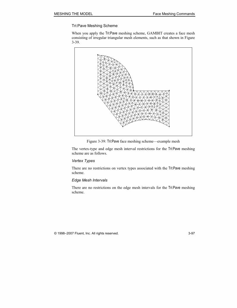
MESHING THE MODEL Face Meshing Commands
© 1998–2007 Fluent, Inc. All rights reserved. 3-97
Tri:Pave Meshing Scheme
When you apply the Tri:Pave meshing scheme, GAMBIT creates a face mesh
consisting of irregular triangular mesh elements, such as that shown in Figure
3-39.
Figure 3-39: Tri:Pave face meshing scheme—example mesh
The vertex-type and edge mesh interval restrictions for the Tri:Pave meshing
scheme are as follows.
Vertex Types
There are no restrictions on vertex types associated with the Tri:Pave meshing
scheme.
Edge Mesh Intervals
There are no restrictions on the edge mesh intervals for the Tri:Pave meshing
scheme.
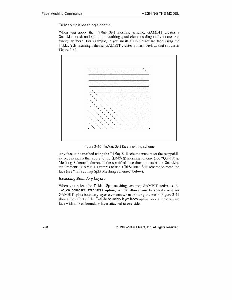
Face Meshing Commands MESHING THE MODEL
3-98 © 1998–2007 Fluent, Inc. All rights reserved.
Tri:Map Split Meshing Scheme
When you apply the Tri:Map Split meshing scheme, GAMBIT creates a
Quad:Map mesh and splits the resulting quad elements diagonally to create a
triangular mesh. For example, if you mesh a simple square face using the
Tri:Map Split meshing scheme, GAMBIT creates a mesh such as that shown in
Figure 3-40.
Figure 3-40: Tri:Map Split face meshing scheme
Any face to be meshed using the Tri:Map Split scheme must meet the mappabil-
ity requirements that apply to the Quad:Map meshing scheme (see “Quad:Map
Meshing Scheme,” above). If the specified face does not meet the Quad:Map requirements, GAMBIT attempts to use a Tri:Submap Split scheme to mesh the
face (see “Tri:Submap Split Meshing Scheme,” below).
Excluding Boundary Layers
When you select the Tri:Map Split meshing scheme, GAMBIT activates the
Exclude boundary layer faces option, which allows you to specify whether GAMBIT splits boundary layer elements when splitting the mesh. Figure 3-41
shows the effect of the Exclude boundary layer faces option on a simple square
face with a fixed boundary layer attached to one side.

MESHING THE MODEL Face Meshing Commands
© 1998–2007 Fluent, Inc. All rights reserved. 3-99
(a) Exclude boundary layer faces on (b) Exclude boundary layer faces off
Figure 3-41: Tri:Map Split—effect of Exclude boundary layer faces option
Vertex Types
Vertex type restrictions for the Tri:Map Split meshing scheme are identical to
those for the Quad:Map mesh scheme (see “Quad:Map Meshing Scheme,”
above). If the vertex types do not exactly meet the Quad:Map vertex type criteria, GAMBIT attempts to change vertex types where necessary to create
the mapped mesh and execute the Tri:Map Split operation.
Edge Mesh Intervals
Edge mesh interval restrictions for the Tri:Map Split meshing scheme are identi-
cal to those for the Quad:Map mesh scheme (see “Quad:Map Meshing
Scheme,” above).
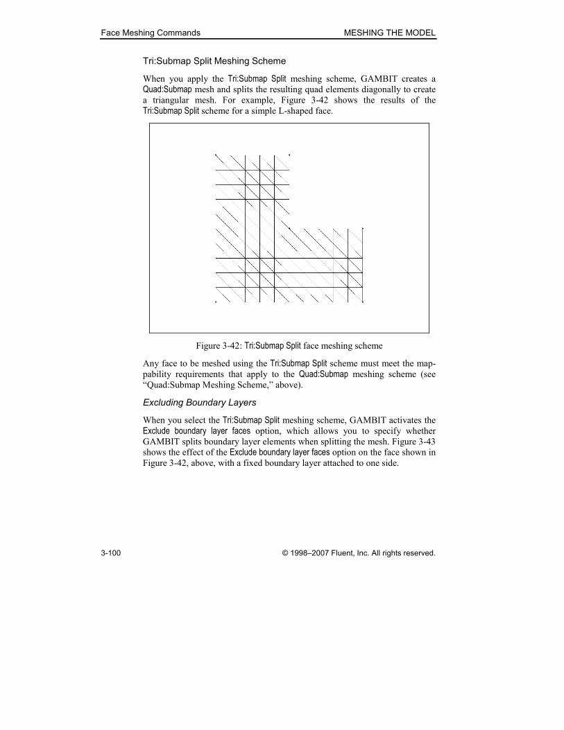
Face Meshing Commands MESHING THE MODEL
3-100 © 1998–2007 Fluent, Inc. All rights reserved.
Tri:Submap Split Meshing Scheme
When you apply the Tri:Submap Split meshing scheme, GAMBIT creates a
Quad:Submap mesh and splits the resulting quad elements diagonally to create
a triangular mesh. For example, Figure 3-42 shows the results of the
Tri:Submap Split scheme for a simple L-shaped face.
Figure 3-42: Tri:Submap Split face meshing scheme
Any face to be meshed using the Tri:Submap Split scheme must meet the map-
pability requirements that apply to the Quad:Submap meshing scheme (see
“Quad:Submap Meshing Scheme,” above).
Excluding Boundary Layers
When you select the Tri:Submap Split meshing scheme, GAMBIT activates the
Exclude boundary layer faces option, which allows you to specify whether GAMBIT splits boundary layer elements when splitting the mesh. Figure 3-43
shows the effect of the Exclude boundary layer faces option on the face shown in Figure 3-42, above, with a fixed boundary layer attached to one side.

MESHING THE MODEL Face Meshing Commands
© 1998–2007 Fluent, Inc. All rights reserved. 3-101
(a) Exclude boundary layer faces on (b) Exclude boundary layer faces off
Figure 3-43: Tri:Submap Split—effect of Exclude boundary layer faces option
Vertex Types
Vertex type restrictions for the Tri:Submap Split meshing scheme are identical
to those for the Quad:Submap mesh scheme (see “Quad:Submap Meshing
Scheme,” above). If the vertex types do not exactly meet the Quad:Submap vertex type criteria, GAMBIT attempts to change vertex types where neces-
sary to create the submapped mesh and execute the Tri:Submap Split operation.
Edge Mesh Intervals
Edge mesh interval restrictions for the Tri:Submap Split meshing scheme are
identical to those for the Quad:Submap mesh scheme (see “Quad:Submap
Meshing Scheme,” above).
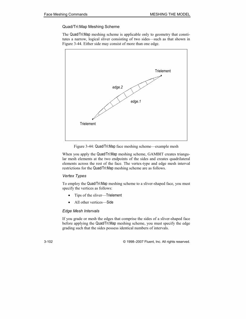
Face Meshing Commands MESHING THE MODEL
3-102 © 1998–2007 Fluent, Inc. All rights reserved.
Quad/Tri:Map Meshing Scheme
The Quad/Tri:Map meshing scheme is applicable only to geometry that consti-
tutes a narrow, logical sliver consisting of two sides—such as that shown in
Figure 3-44. Either side may consist of more than one edge.
Trielement
edge.2
Trielement
edge.1
Figure 3-44: Quad/Tri:Map face meshing scheme—example mesh
When you apply the Quad/Tri:Map meshing scheme, GAMBIT creates triangu-
lar mesh elements at the two endpoints of the sides and creates quadrilateral
elements across the rest of the face. The vertex-type and edge mesh interval
restrictions for the Quad/Tri:Map meshing scheme are as follows.
Vertex Types
To employ the Quad/Tri:Map meshing scheme to a sliver-shaped face, you must
specify the vertices as follows:
• Tips of the sliver—Trielement
• All other vertices—Side
Edge Mesh Intervals
If you grade or mesh the edges that comprise the sides of a sliver-shaped face
before applying the Quad/Tri:Map meshing scheme, you must specify the edge
grading such that the sides possess identical numbers of intervals.
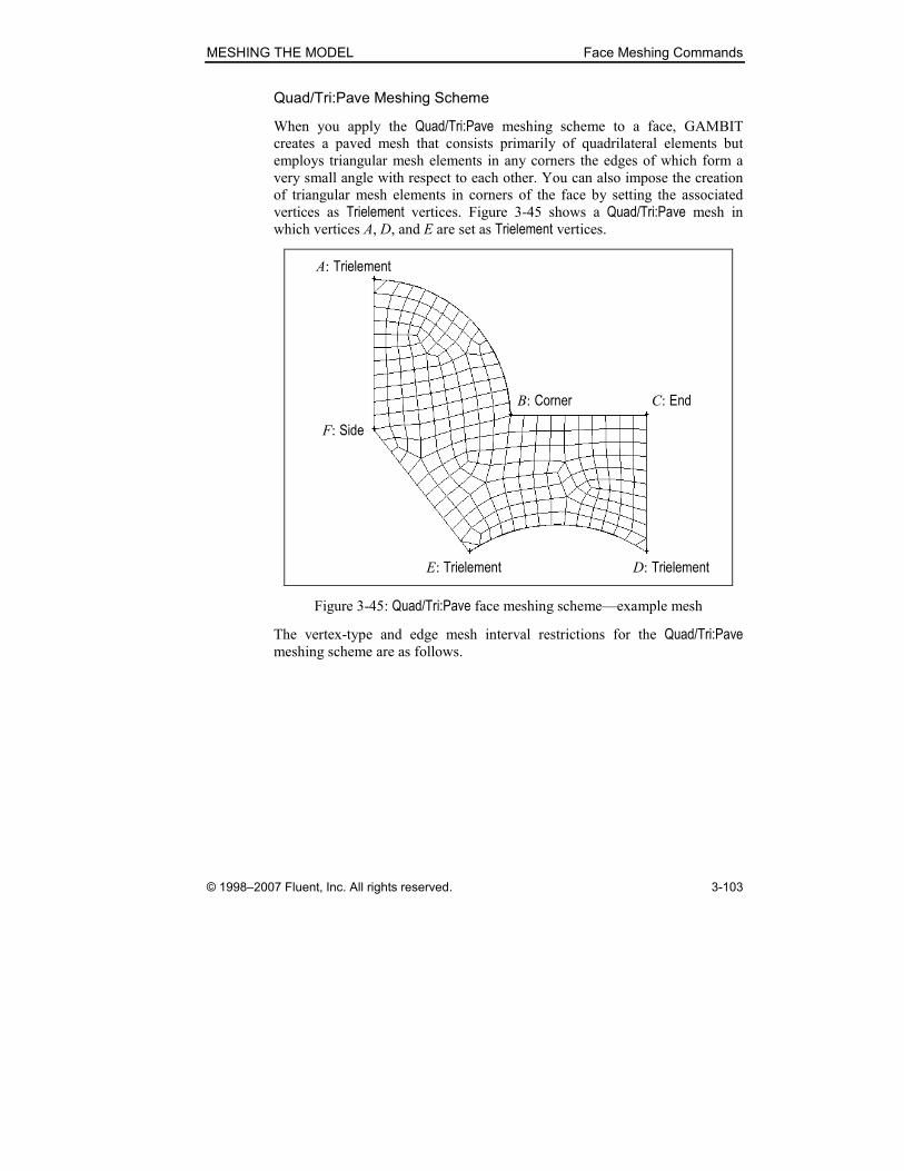
MESHING THE MODEL Face Meshing Commands
© 1998–2007 Fluent, Inc. All rights reserved. 3-103
Quad/Tri:Pave Meshing Scheme
When you apply the Quad/Tri:Pave meshing scheme to a face, GAMBIT
creates a paved mesh that consists primarily of quadrilateral elements but
employs triangular mesh elements in any corners the edges of which form a
very small angle with respect to each other. You can also impose the creation
of triangular mesh elements in corners of the face by setting the associated
vertices as Trielement vertices. Figure 3-45 shows a Quad/Tri:Pave mesh in
which vertices A, D, and E are set as Trielement vertices.
A: Trielement
B: Corner
E: Trielement D: Trielement
C: End
F: Side
Figure 3-45: Quad/Tri:Pave face meshing scheme—example mesh
The vertex-type and edge mesh interval restrictions for the Quad/Tri:Pave meshing scheme are as follows.

Face Meshing Commands MESHING THE MODEL
3-104 © 1998–2007 Fluent, Inc. All rights reserved.
Vertex Types
There are no restrictions on vertex types associated with the Quad/Tri:Pave meshing scheme, however, you can enforce the creation of either triangular or
quadrilateral corner elements by means of the Trielement or Notrielement vertex types, respectively, as follows:
• If you specify a vertex as a Notrielement vertex, GAMBIT creates a
quadrilateral element at the vertex location regardless of the angle
between its associated edges.
• If you specify a vertex as a Trielement vertex, GAMBIT creates a trian-
gular element at the vertex location regardless of the angle between its
associated edges.
Edge Mesh Intervals
If you grade or mesh all of the edges that comprise the boundary of a face
before applying the Quad/Tri:Pave meshing scheme, you must specify the grad-
ing such that
TT NIN −=
is an even number, where TI is the total number of mesh intervals on all
edges, and TN is the total number of triangle mesh elements. If you grade
some, but not all, of the edges, GAMBIT automatically meshes the ungraded
edges such that N is an even number.

MESHING THE MODEL Face Meshing Commands
© 1998–2007 Fluent, Inc. All rights reserved. 3-105
Quad/Tri:Wedge Primitive Meshing Scheme
The Quad/Tri:Wedge Primitive meshing scheme allows you to create a radial
mesh on a three-sided face. (NOTE: Any side of the three-sided face may con-
sist of more than one edge.) When you apply the Quad/Tri:Wedge Primitive meshing scheme, GAMBIT creates a mapped mesh that includes a group of
triangular mesh elements emanating from common endpoint (see Figure
3-46).
B: End
A: Trielement
C: End
Figure 3-46: Quad/Tri:Wedge Primitive face meshing scheme—example mesh
The vertex-type and edge mesh interval restrictions for the Quad/Tri:Wedge Primitive meshing scheme are as follows.
Vertex Types
The Quad/Tri:Wedge Primitive meshing scheme requires that the vertices at the
corners of the three sides of the face are specified as End vertices (see Figure 3-47) and that all other vertices are specified as Side vertices.
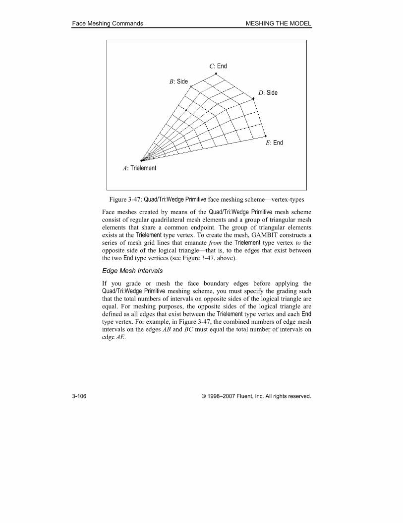
Face Meshing Commands MESHING THE MODEL
3-106 © 1998–2007 Fluent, Inc. All rights reserved.
C: End
A: Trielement
E: End
B: Side
D: Side
Figure 3-47: Quad/Tri:Wedge Primitive face meshing scheme—vertex-types
Face meshes created by means of the Quad/Tri:Wedge Primitive mesh scheme
consist of regular quadrilateral mesh elements and a group of triangular mesh
elements that share a common endpoint. The group of triangular elements
exists at the Trielement type vertex. To create the mesh, GAMBIT constructs a
series of mesh grid lines that emanate from the Trielement type vertex to the opposite side of the logical triangle—that is, to the edges that exist between
the two End type vertices (see Figure 3-47, above).
Edge Mesh Intervals
If you grade or mesh the face boundary edges before applying the
Quad/Tri:Wedge Primitive meshing scheme, you must specify the grading such
that the total numbers of intervals on opposite sides of the logical triangle are
equal. For meshing purposes, the opposite sides of the logical triangle are
defined as all edges that exist between the Trielement type vertex and each End type vertex. For example, in Figure 3-47, the combined numbers of edge mesh
intervals on the edges AB and BC must equal the total number of intervals on
edge AE.
MESHING THE MODEL Face Meshing Commands
© 1998–2007 Fluent, Inc. All rights reserved. 3-107
Specifying Scheme Smoother Algorithm
If you mesh a face with Quad element types using a Map meshing scheme,
GAMBIT allows you to automatically smooth the mesh during meshing by
means of Smoother options on the Mesh Faces form. (NOTE: You can also
smooth any existing face mesh by means of the Smooth Face Meshes com-
mand (see Section 3.3.3, below).)
GAMBIT provides the following Smoother options for faces.
Option Algorithm
None No smoother applied during meshing
Thom-Mid Thomas-Middlecoff
The Thom-Mid option is useful when mesh nodes on the face boundary edges
are bunched together in certain sections of the edges. Such bunching can
affect the smoothness of the interior face mesh. The algorithm tends to smooth
the face mesh only (or primarily) in those regions affected by the bunched
edge nodes.
� NOTE: The Thom-Mid option applies only to planar faces. If you specify the Thom-Mid option when meshing a non-planar face, GAMBIT meshes the face
without smoothing and displays a warning message in the Transcript window.
Face Meshing Commands MESHING THE MODEL
3-108 © 1998–2007 Fluent, Inc. All rights reserved.
Specifying Node Spacing
When you specify mesh node spacing on the Mesh Faces form, GAMBIT
applies the specification to all edges associated with any specified faces that
are not currently graded or meshed. GAMBIT provides three different ways to
specify the number of intervals on the edges of a face.
• Interval count
• Interval size
• Shortest edge (%)
For a description of the three edge mesh interval spacing options listed above,
see “Specifying Node Spacing” in Section 3.2.1.
Specifying Projection Intervals
When you apply a Quad:Map or Quad:Submap scheme to a face that is bounded
by two closed-loop edges, such as a cylindrical or annular face, GAMBIT
allows you to specify the number of “projection” intervals between the bound-
ing edges. The number of intervals is specified by means of the Proj Intervals text field on the Mesh Faces form.
As an example of the effect of the Proj Intervals value, consider the two faces shown in Figure 3-48. The cylindrical face (Figure 3-48(a)) has a height of 10
and a constant radius of 4. The annular face (Figure 3-48(b)) has inner and
outer radii of 2 and 6, respectively.
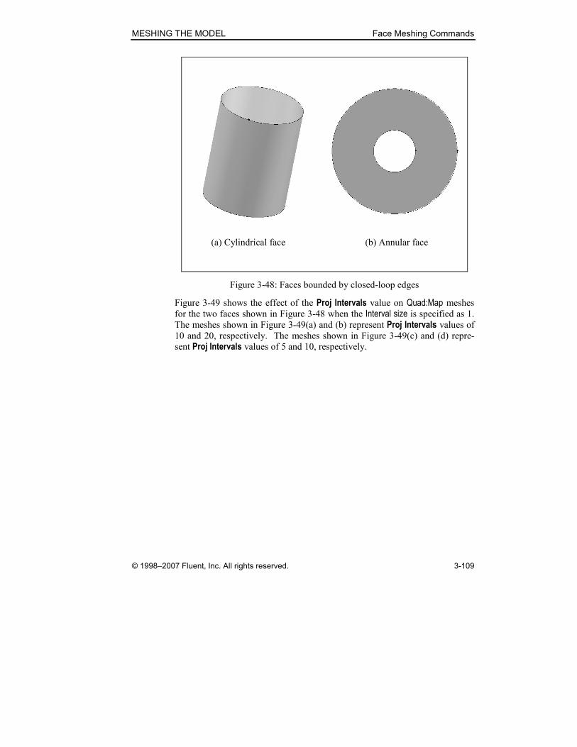
MESHING THE MODEL Face Meshing Commands
© 1998–2007 Fluent, Inc. All rights reserved. 3-109
(a) Cylindrical face (b) Annular face
Figure 3-48: Faces bounded by closed-loop edges
Figure 3-49 shows the effect of the Proj Intervals value on Quad:Map meshes
for the two faces shown in Figure 3-48 when the Interval size is specified as 1. The meshes shown in Figure 3-49(a) and (b) represent Proj Intervals values of 10 and 20, respectively. The meshes shown in Figure 3-49(c) and (d) repre-
sent Proj Intervals values of 5 and 10, respectively.

Face Meshing Commands MESHING THE MODEL
3-110 © 1998–2007 Fluent, Inc. All rights reserved.
(a) Proj Intervals = 10 (b) Proj Intervals = 20
(c) Proj Intervals = 5 (d) Proj Intervals = 10
Figure 3-49: Effect of Proj Intervals value
Specifying Face Meshing Options
GAMBIT includes the following primary options on the Mesh Faces form:
• Mesh
• Remove old mesh
• Remove lower mesh
• Ignore size functions
Mesh Option
If you select the Mesh option, GAMBIT meshes the picked face(s) according
to the parameters as currently specified on the Mesh Faces form. If you Apply the meshing specifications without selecting the Mesh option, GAMBIT
applies the currently specified mesh parameters to the face(s) but does not
create the mesh.

MESHING THE MODEL Face Meshing Commands
© 1998–2007 Fluent, Inc. All rights reserved. 3-111
Remove old mesh Option
If you select the Remove old mesh option, GAMBIT removes any currently
existing mesh from the specified face(s) before creating the new face
mesh(es). GAMBIT also enables the Remove lower mesh option (see below), which specifies whether or not to remove the mesh on pre-meshed boundary
edges. If you do not select the Remove lower mesh option, GAMBIT retains
any existing pre-assigned edge mesh(es) when meshing the face.
Remove lower mesh Option
As noted above, when you select the Remove old mesh option, GAMBIT
enables the Remove lower mesh option, which allows you to specify whether or not to remove the mesh on pre-meshed boundary edges—that is, edges for
which mesh intervals and grading specifications are assigned (using the Mesh Edges command) prior to meshing the face.
• If you select the Remove lower mesh option, GAMBIT removes any
pre-assigned edge-mesh interval assignments but retains pre-assigned
edge-mesh grading specifications.
• If you do not select the Remove lower mesh option, GAMBIT retains all
pre-assigned edge-mesh interval and grading assignments.
Ignore size functions Option
If you select the Ignore size functions option, GAMBIT ignores any existing
size function specifications that would otherwise affect the face mesh.

Face Meshing Commands MESHING THE MODEL
3-112 © 1998–2007 Fluent, Inc. All rights reserved.
Using the Mesh Faces Form
To open the Mesh Faces form (see below), click the Mesh command button on
the Mesh/Face subpad.
The Mesh Faces form contains the following specifications.
Faces � specifies the faces to be meshed.
Scheme: —————————————————————————
���� Apply specifies that the meshing scheme indicated on the option
button is applied to all currently picked faces.
Default resets the meshing scheme option button to its default algo-
rithm value (Undetermined).
Elements: ————————————————————————
Quad � Tri Quad/Tri
specifies the mesh element shape. (NOTE: Each
Elements option is associated with its own set of allow-able Type options (see “Specifying Scheme Elements,”
above).)
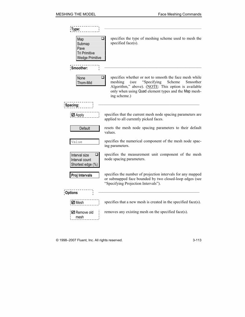
MESHING THE MODEL Face Meshing Commands
© 1998–2007 Fluent, Inc. All rights reserved. 3-113
Type: ————————————————————————
Map � Submap Pave Tri Primitive Wedge Primitive
specifies the type of meshing scheme used to mesh the
specified face(s).
Smoother: ————————————————————————
None � Thom-Mid
specifies whether or not to smooth the face mesh while
meshing (see “Specifying Scheme Smoother
Algorithm,” above). (NOTE: This option is available
only when using Quad element types and the Map mesh-
ing scheme.)
Spacing: —————————————————————————
���� Apply specifies that the current mesh node spacing parameters are
applied to all currently picked faces.
Default resets the mesh node spacing parameters to their default
values.
Value specifies the numerical component of the mesh node spac-
ing parameters.
Interval size � Interval count Shortest edge (%)
specifies the measurement unit component of the mesh
node spacing parameters.
Proj Intervals specifies the number of projection intervals for any mapped
or submapped face bounded by two closed-loop edges (see
“Specifying Projection Intervals”).
Options —————————————————————————
���� Mesh specifies that a new mesh is created in the specified face(s).
���� Remove old mesh
removes any existing mesh on the specified face(s).

Face Meshing Commands MESHING THE MODEL
3-114 © 1998–2007 Fluent, Inc. All rights reserved.
���� Remove lower mesh
removes pre-assigned edge-mesh interval information for
the specified face(s). (NOTE: GAMBIT retains any pre-
assigned grading specifications.)
���� Ignore size functions
specifies that GAMBIT ignores any existing size-function
specifications that would otherwise affect the face mesh.
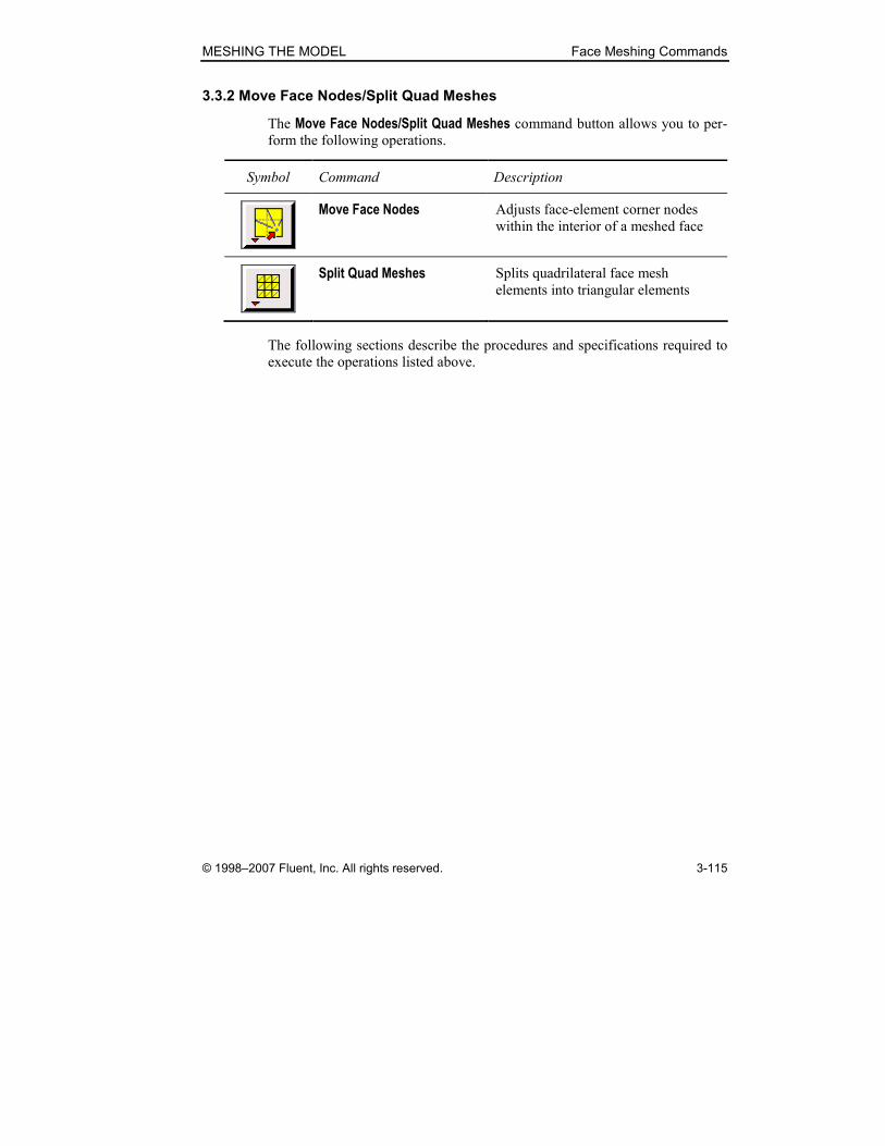
MESHING THE MODEL Face Meshing Commands
© 1998–2007 Fluent, Inc. All rights reserved. 3-115
3.3.2 Move Face Nodes/Split Quad Meshes
The Move Face Nodes/Split Quad Meshes command button allows you to per-
form the following operations.
Symbol Command Description
Move Face Nodes Adjusts face-element corner nodes
within the interior of a meshed face
Split Quad Meshes Splits quadrilateral face mesh
elements into triangular elements
The following sections describe the procedures and specifications required to
execute the operations listed above.

Face Meshing Commands MESHING THE MODEL
3-116 © 1998–2007 Fluent, Inc. All rights reserved.
Move Face Nodes
The Move Face Nodes operation (face move meshnodes command) reposi-
tions mesh nodes that exist in the interior of a meshed face. You can move the
mesh nodes either by means of the Move Face Nodes form or by means of the
mouse.
To move a face node, you must specify the following parameters and options:
• The meshed face upon which the nodes exist
• The number of the node to be moved
• The coordinates of the new node location
• Smooth option
The following paragraphs describe the specifications listed above as well as
the procedure required to move face mesh nodes by means of the mouse.
Specifying the Face
When you specify a face for which mesh nodes are to be moved, GAMBIT
highlights the face the graphics window and displays the corresponding mesh
as a series of grid lines. Face nodes are located at the intersections of the grid
lines.
Specifying the Node Number
To specify a node to be moved, you must input the corresponding node num-
ber on the Move Face Nodes form. To open a complete list of available node
numbers associated with the specified face:
1. Click the Nodes pick list button.
2. Click All on the Nodes pick list form.
When you click the All command button, GAMBIT fills the Nodes pick list with the numbers of all nodes associated with the specified face and displays
the nodes on the mesh grid in the graphics window. (NOTE: The Nodes list includes only face-element corner nodes that are interior to the face.) When
you select a node number from the Nodes pick list, GAMBIT highlights the
node in the graphics window.
To move a series of nodes, select and specify the coordinates of each node in
turn. When you have selected and moved all nodes, click Apply on the Move Face Nodes form.
MESHING THE MODEL Face Meshing Commands
© 1998–2007 Fluent, Inc. All rights reserved. 3-117
Specifying Node Coordinates
To specify the new coordinates of a face mesh node, you must specify the ref-
erence coordinate system and the coordinate parameters corresponding to the
new node location. You can input the coordinate parameters with respect to
either the Global or Local coordinate system. If you specify a node location
that does not lie on the specified face, GAMBIT automatically adjusts the
coordinate parameters so that the new node location lies on the face.
Using the Mouse to Move Face Nodes
To use the mouse to move face nodes:
1. Pick the face upon which the nodes are to be moved.
2. Shift-right-click in the graphics window to accept the selection.
3. Pick (Shift-left-click) the node to be moved and drag it to its new
location.
To move a series of mesh nodes, pick and drag each node in turn. When you
have finished moving all nodes, Shift-right-click the mouse in the graphics
window to accept and apply the new node positions.
Specifying the Smooth Option
If you specify the Smooth option when moving a node, GAMBIT smoothes the
entire mesh by adjusting the positions of mesh nodes other than the moved
node. If you specify the Smooth option for a face that includes a boundary layer, the effect of the smoothing operation depends on whether the node to be
moved exists inside or outside the boundary layer, as follows:
• If the specified node is outside the boundary layer, GAMBIT does not
alter the positions of any mesh nodes within the boundary layer.
• If the specified node is inside the boundary layer, GAMBIT adjusts the
other nodes within the boundary layer along straight lines and adjusts
the mesh outside the boundary layer accordingly.
As an example of the effect of the Smooth option, consider the square, meshed
face shown in Figure 3-50, which includes a six-row boundary layer on its
bottom edge.

Face Meshing Commands MESHING THE MODEL
3-118 © 1998–2007 Fluent, Inc. All rights reserved.
B.L.
A
B
Figure 3-50: Square meshed face with boundary layer
Figure 3-51 and Figure 3-52 show the effects of the Smooth option when mov-
ing a single node located either outside (node A) or inside (node B) the bound-
ary layer.
• If you move node A and do not select the Smooth option, GAMBIT
does not adjust the positions of any other mesh nodes (see Figure
3-51(a)).
• If you move node A and do select the Smooth option, GAMBIT adjusts
the positions of other mesh nodes outside the boundary layer but does
not adjust the positions of nodes within the boundary layer (see Figure
3-51(b)).
• If you move node B and do not select the Smooth option, GAMBIT
does not adjust the positions of any other mesh nodes (see Figure
3-52(a)).
• If you move node B and do select the Smooth option, GAMBIT adjusts
the positions of several other mesh nodes inside the boundary layer
(along straight lines)—which, in turn, affects the mesh outside the
boundary layer (see Figure 3-52(b)).
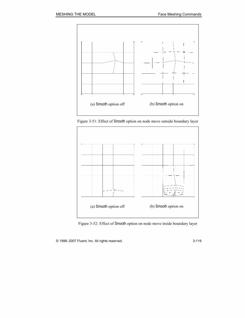
MESHING THE MODEL Face Meshing Commands
© 1998–2007 Fluent, Inc. All rights reserved. 3-119
(a) Smooth option off (b) Smooth option on
Figure 3-51: Effect of Smooth option on node move outside boundary layer
(a) Smooth option off (b) Smooth option on
Figure 3-52: Effect of Smooth option on node move inside boundary layer
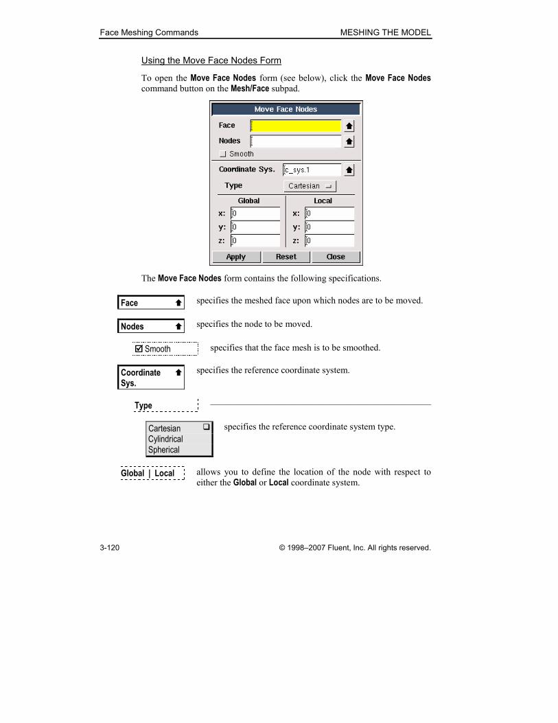
Face Meshing Commands MESHING THE MODEL
3-120 © 1998–2007 Fluent, Inc. All rights reserved.
Using the Move Face Nodes Form
To open the Move Face Nodes form (see below), click the Move Face Nodes command button on the Mesh/Face subpad.
The Move Face Nodes form contains the following specifications.
Face � specifies the meshed face upon which nodes are to be moved.
Nodes � specifies the node to be moved.
���� Smooth specifies that the face mesh is to be smoothed.
Coordinate �
Sys.
specifies the reference coordinate system.
Type ————————————————————————
Cartesian � Cylindrical Spherical
specifies the reference coordinate system type.
Global | Local allows you to define the location of the node with respect to
either the Global or Local coordinate system.

MESHING THE MODEL Face Meshing Commands
© 1998–2007 Fluent, Inc. All rights reserved. 3-121
Split Quad Meshes
The Split Quad Meshes operation (face quadsplit command) splits quad-
rilateral face mesh elements into triangular elements. To accomplish the split
operation, GAMBIT creates mesh edges between existing nodes of the quad-
rilateral mesh but does not alter the original positions of the mesh nodes in the
process.
As an example of the Split Quad Meshes operation, consider the quad-meshed
face shown in Figure 3-53(a). In this example, the face is bounded by an edge
loop consisting of five edges and has been meshed by means of a Quad:Pave scheme.
(a) Before Split Quad operation (b) After Split Quad operation
Figure 3-53: Split Quad Meshes example
If you perform the Split Quad Meshes operation on the face shown in Figure 3-53(a), GAMBIT splits the quadrilateral mesh elements into triangular ele-
ments to create the mesh shown in Figure 3-53(b).
Excluding Boundary Layer Faces
The Split Quad Meshes form includes an Exclude boundary layer faces option that allows you to prohibit GAMBIT from splitting quad mesh elements in
face boundary layers. As an example of the effect of the Exclude boundary layer faces option, consider the meshed face shown in Figure 3-54. The face is simi-
lar to that shown in Figure 3-53, above, but includes a boundary layer along
the left side.

Face Meshing Commands MESHING THE MODEL
3-122 © 1998–2007 Fluent, Inc. All rights reserved.
Boundary layer
Figure 3-54: Quad-meshed face with boundary layer
Figure 3-55 shows the effect of the Exclude boundary layer faces option on the Split Quad Meshes operation for the face shown in Figure 3-54.
(a) Exclude boundary layer faces off (b) Exclude boundary layer faces on
Figure 3-55: Effect of Exclude boundary layer faces option

MESHING THE MODEL Face Meshing Commands
© 1998–2007 Fluent, Inc. All rights reserved. 3-123
The effects can be summarized as follows:
• If you do not select the Exclude boundary layer faces option when executing the Split Quad Meshes operation, GAMBIT splits all mesh
quads on the face (see Figure 3-55(a)).
• If you do select the Exclude boundary layer faces option, GAMBIT splits
only the quad mesh elements that do not constitute parts of the bound-
ary layer (see Figure 3-55(b)).
Using the Split Quad Meshes Form
To open the Split Quad Meshes form (see below), click the Split command
button on the Mesh/Face subpad.
The Split Quad Meshes form contains the following specifications.
Faces � specifies the meshed face(s) for which the quad mesh is to be
split into triangular elements.
���� Exclude boundary layer faces
specifies that quad face elements in boundary-layer regions are
to be excluded from the split operation.

Face Meshing Commands MESHING THE MODEL
3-124 © 1998–2007 Fluent, Inc. All rights reserved.
3.3.3 Smooth Face Meshes
The Smooth Face Meshes operation (face smooth command) adjusts the
node locations for one or more face meshes. When you smooth a face mesh,
GAMBIT automatically adjusts the mesh node locations to improve the uni-
formity of the spacing between nodes across the face. To smooth a face mesh,
you must specify the following parameters:
• The face(s) for which the mesh is to be smoothed
• The smoothing scheme
Specifying the Smoothing Scheme
GAMBIT provides the following smoothing schemes:
• Length-weighted Laplacian (L-W Laplacian)
• Centroid Area (Centroid Area)
• Winslow (Winslow)
The following table summarizes the basic features of the algorithm employed
by each scheme.
Algorithm Features
Length-weighted Laplacian • Uses the average edge length of the
elements surrounding each node
• Tends to average element edge lengths
Centroid Area • Equalizes areas of adjacent elements
Winslow • Optimizes element shapes with respect
to perpendicularity
• Applies only to quadratic elements
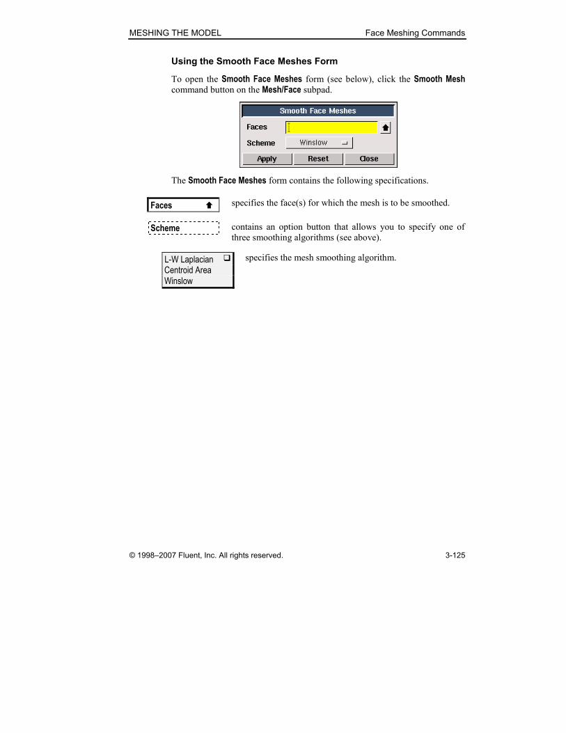
MESHING THE MODEL Face Meshing Commands
© 1998–2007 Fluent, Inc. All rights reserved. 3-125
Using the Smooth Face Meshes Form
To open the Smooth Face Meshes form (see below), click the Smooth Mesh command button on the Mesh/Face subpad.
The Smooth Face Meshes form contains the following specifications.
Faces � specifies the face(s) for which the mesh is to be smoothed.
Scheme contains an option button that allows you to specify one of
three smoothing algorithms (see above).
L-W Laplacian � Centroid Area Winslow
specifies the mesh smoothing algorithm.

Face Meshing Commands MESHING THE MODEL
3-126 © 1998–2007 Fluent, Inc. All rights reserved.
3.3.4 Set Face Vertex Type
The Set Face Vertex Type operation (face modify command) defines the
characteristics of face meshing and/or boundary layer construction operations
in the vicinity of a specified vertex. The vertex-type specifications also deter-
mine which face meshing scheme GAMBIT selects as the default scheme.
To set the type for one or more vertices, you must specify the following input
parameters.
• Face
• Type
• Vertices
• Boundary layer only option
The Face, Type, and Vertices parameters define the vertex type specification.
The Boundary layer only option specifies whether the specification applies to meshing and/or boundary layer construction operations.
Specifying the Face
GAMBIT vertex types are specific to the faces upon which they are set; there-
fore, to specify the type designation of an individual vertex, you must also
specify a face associated with that vertex. An individual vertex may possess as
many vertex type designations as the number of faces to which it is attached.
For example, it is possible for a vertex to possess a Side type designation with respect to one face and an End type designation with respect to another face.
Specifying Vertex Type
The structure of any face mesh in the vicinity of an individual vertex on its
boundary is a function of the face meshing scheme and vertex type. GAMBIT
provides six vertex types (see Figure 3-56):
• End
• Side
• Corner
• Reversal
• Trielement
• Notrielement

MESHING THE MODEL Face Meshing Commands
© 1998–2007 Fluent, Inc. All rights reserved. 3-127
(a) End
End vertex
(c) Corner
Corner
vertex
(d) Reversal
Reversal
vertex
(e) Trielement
Trielement
vertex
(f) Notrielement
Notrielement
vertex
(b) Side
Side vertex
Figure 3-56: Face vertex types
Each vertex type differs from the others in the following ways:
• Number of face mesh lines that intersect the vertex
• Angle between the edges immediately adjacent to the vertex
• Face mesh scheme to which it applies
The following table summarizes the characteristics of the vertex types shown
in Figure 3-56.

Face Meshing Commands MESHING THE MODEL
3-128 © 1998–2007 Fluent, Inc. All rights reserved.
Vertex Type
Intersecting
Grid Lines
Angle Between Edges
Applicable
Mesh Scheme
End 0 °<<° 1200 θ Quad:Map Quad:Pave Quad:Submap Quad:Tri Primitive Quad/Tri:Map Quad/Tri:Pave Quad/Tri:Wedge Primitive Tri:Pave
Side 1 °<≤° 216120 θ Quad:Map Quad:Pave Quad:Submap Quad:Tri Primitive Quad/Tri:Map Quad/Tri:Wedge Primitive
Corner 2 °<≤° 5.308216 θ Quad:Map Quad:Submap
Reversal 3 °<≤° 3605.308 θ Quad:Map Quad:Submap
Trielement 0 Acute
(User specified)
Quad:Tri Primitive Quad/Tri:Map Quad/Tri:Wedge Primitive
Notrielement 0 Acute
(User specified) Quad:Tri Primitive Quad/Tri:Map Quad/Tri:Wedge Primitive
� NOTE: GAMBIT ignores vertex types when meshing a face according to the
Pave mesh scheme.
The following sections describe the general effect of each vertex type on the
shape of the face mesh in the vicinity of a specified vertex.
MESHING THE MODEL Face Meshing Commands
© 1998–2007 Fluent, Inc. All rights reserved. 3-129
End Vertex Type
When you specify a vertex as the End vertex type and do not specify a Pave meshing scheme, GAMBIT creates the face mesh such that only two mesh
element edges intersect at the vertex (see Figure 3-56(a)). As a result, the
mapped and submapped face mesh patterns on both sides of the End vertex terminate at the edges adjacent to the vertex.
Side Vertex Type
When you specify a vertex as the Side vertex type and do not specify a Pave meshing scheme, GAMBIT creates the face mesh such that three mesh ele-
ment edges intersect at the vertex (see Figure 3-56(b)). GAMBIT treats the
two topological edges that are adjacent to the vertex as a single edge for the
purposes of meshing.
Corner Vertex Type
When you specify a vertex as the Corner vertex type and do not specify a Pave meshing scheme, GAMBIT creates the face mesh such that four mesh element
edges intersect at the vertex (see Figure 3-56(c)). The Corner vertex type can-not be applied to vertices the adjacent edges of which form angles less than
180°.
Reversal Vertex Type
When you specify a vertex as the Reversal vertex type, GAMBIT creates the
face mesh such that five mesh element edges intersect at the vertex (see
Figure 3-56(d)). When you apply a Submap meshing scheme to a face that
includes a Reversal vertex, GAMBIT creates a line of mesh edges that extends
from the Reversal vertex to a topological edge on an opposite side of the face. GAMBIT treats the resulting line and each adjacent edge as a single edge for
the purposes of meshing.
Trielement and Notrielement Vertex Types
When you specify a vertex as the Trielement vertex type, GAMBIT creates a
triangular element (see Figure 3-56(e)) at the vertex, regardless of the default
element type that would otherwise be created using either the Quad/Tri:Map, Tri:Primitive, or Quad/Tri:Wedge Primitive face meshing schemes.
When you specify a Notrielement vertex type, GAMBIT creates a quadrilateral
element at the vertex, regardless of the default element type that would other-
wise be created.
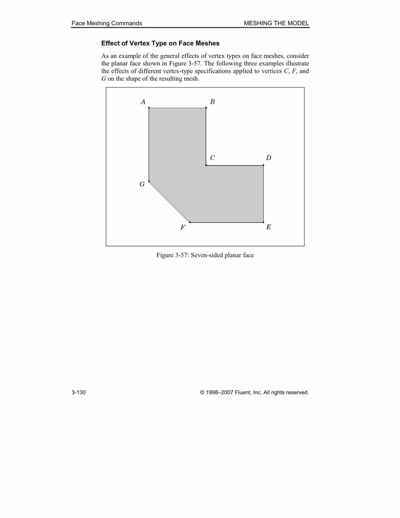
Face Meshing Commands MESHING THE MODEL
3-130 © 1998–2007 Fluent, Inc. All rights reserved.
Effect of Vertex Type on Face Meshes
As an example of the general effects of vertex types on face meshes, consider
the planar face shown in Figure 3-57. The following three examples illustrate
the effects of different vertex-type specifications applied to vertices C, F, and
G on the shape of the resulting mesh.
A
C D
G
F E
B
Figure 3-57: Seven-sided planar face
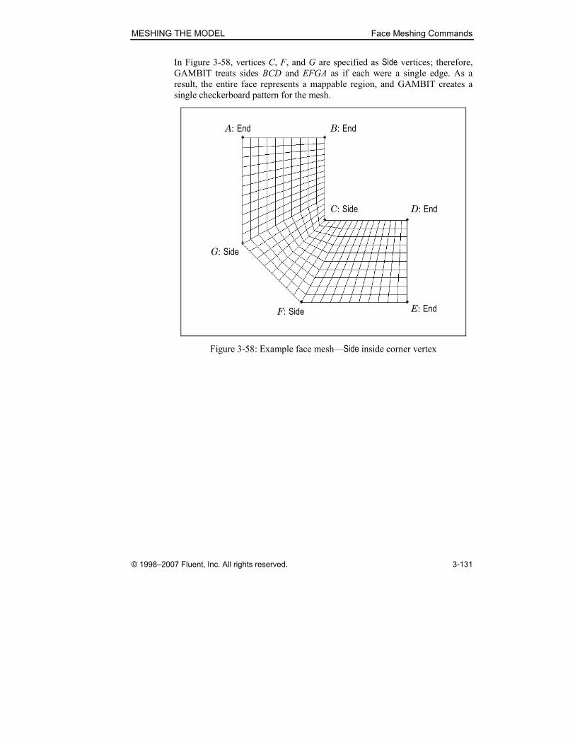
MESHING THE MODEL Face Meshing Commands
© 1998–2007 Fluent, Inc. All rights reserved. 3-131
In Figure 3-58, vertices C, F, and G are specified as Side vertices; therefore, GAMBIT treats sides BCD and EFGA as if each were a single edge. As a
result, the entire face represents a mappable region, and GAMBIT creates a
single checkerboard pattern for the mesh.
A: End
C: Side D: End
G: Side
F: Side E: End
B: End
Figure 3-58: Example face mesh—Side inside corner vertex
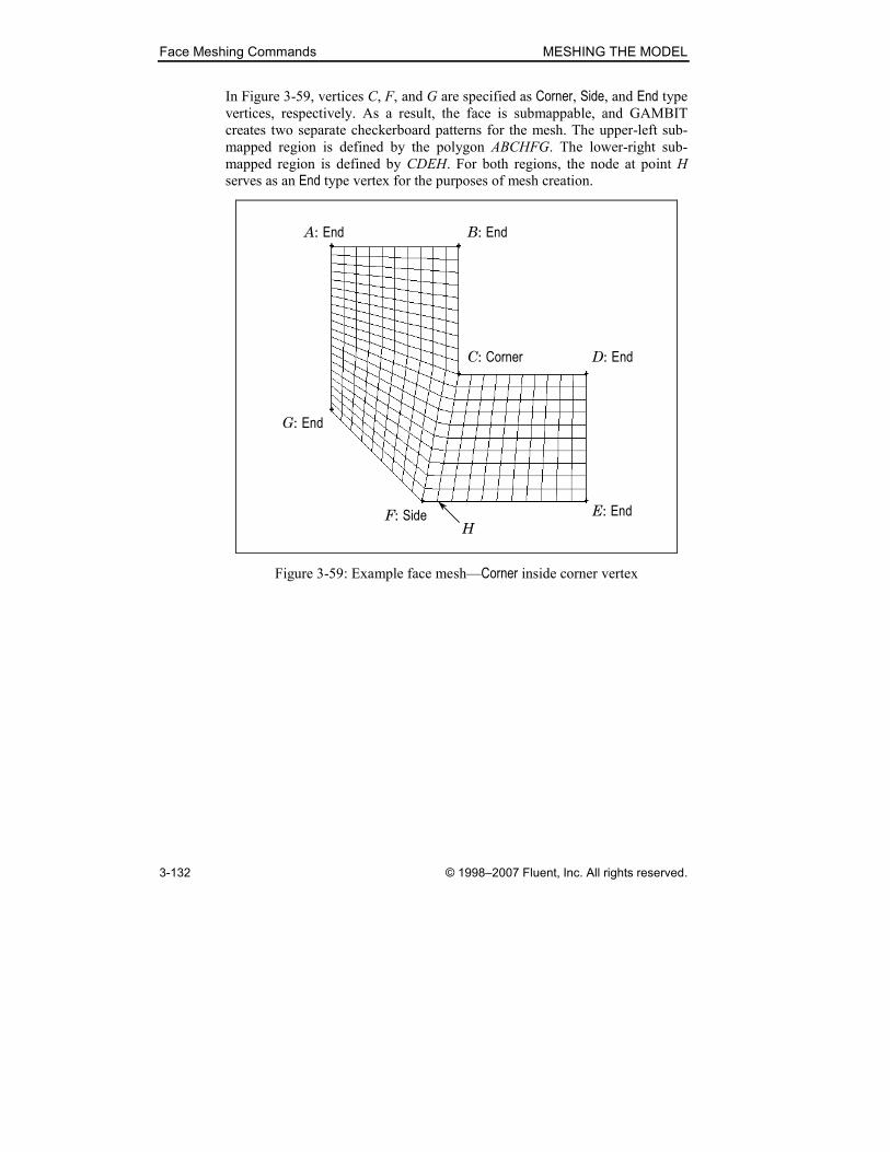
Face Meshing Commands MESHING THE MODEL
3-132 © 1998–2007 Fluent, Inc. All rights reserved.
In Figure 3-59, vertices C, F, and G are specified as Corner, Side, and End type vertices, respectively. As a result, the face is submappable, and GAMBIT
creates two separate checkerboard patterns for the mesh. The upper-left sub-
mapped region is defined by the polygon ABCHFG. The lower-right sub-
mapped region is defined by CDEH. For both regions, the node at point H
serves as an End type vertex for the purposes of mesh creation.
A: End
C: Corner D: End
G: End
F: Side E: End
B: End
H
Figure 3-59: Example face mesh—Corner inside corner vertex
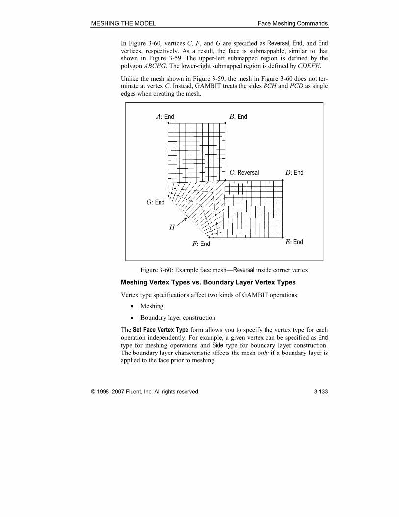
MESHING THE MODEL Face Meshing Commands
© 1998–2007 Fluent, Inc. All rights reserved. 3-133
In Figure 3-60, vertices C, F, and G are specified as Reversal, End, and End vertices, respectively. As a result, the face is submappable, similar to that
shown in Figure 3-59. The upper-left submapped region is defined by the
polygon ABCHG. The lower-right submapped region is defined by CDEFH.
Unlike the mesh shown in Figure 3-59, the mesh in Figure 3-60 does not ter-
minate at vertex C. Instead, GAMBIT treats the sides BCH and HCD as single
edges when creating the mesh.
A: End
C: Reversal D: End
G: End
F: End E: End
B: End
H
Figure 3-60: Example face mesh—Reversal inside corner vertex
Meshing Vertex Types vs. Boundary Layer Vertex Types
Vertex type specifications affect two kinds of GAMBIT operations:
• Meshing
• Boundary layer construction
The Set Face Vertex Type form allows you to specify the vertex type for each
operation independently. For example, a given vertex can be specified as End type for meshing operations and Side type for boundary layer construction. The boundary layer characteristic affects the mesh only if a boundary layer is
applied to the face prior to meshing.
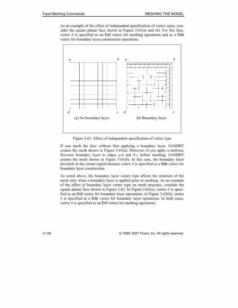
Face Meshing Commands MESHING THE MODEL
3-134 © 1998–2007 Fluent, Inc. All rights reserved.
As an example of the effect of independent specification of vertex types, con-
sider the square planar face shown in Figure 3-61(a) and (b). For this face,
vertex b is specified as an End vertex for meshing operations and as a Side vertex for boundary layer construction operations.
(a) No boundary layer (b) Boundary layer
a b
cd
a b
cd
Figure 3-61: Effect of independent specification of vertex type
If you mesh the face without first applying a boundary layer, GAMBIT
creates the mesh shown in Figure 3-61(a). However, if you apply a uniform,
five-row boundary layer to edges a-b and b-c before meshing, GAMBIT
creates the mesh shown in Figure 3-61(b). In this case, the boundary layer
dovetails in the corner region because vertex b is specified as a Side vertex for boundary layer construction.
As noted above, the boundary layer vertex type affects the structure of the
mesh only when a boundary layer is applied prior to meshing. As an example
of the effect of boundary layer vertex type on mesh structure, consider the
square planar face shown in Figure 3-62. In Figure 3-62(a), vertex b is speci-
fied as an End vertex for boundary layer operations; in Figure 3-62(b), vertex b is specified as a Side vertex for boundary layer operations. In both cases, vertex b is specified as an End vertex for meshing operations.

MESHING THE MODEL Face Meshing Commands
© 1998–2007 Fluent, Inc. All rights reserved. 3-135
(a) Side vertex b (b) End vertex b
a b
cd
a b
cd
Figure 3-62: Effect of boundary layer vertex type
If you apply a uniform, five-row boundary layer to edges a-b and b-c before
meshing the face, GAMBIT creates the meshes shown in Figure 3-62(a) and
(b). In this case, the structure of the mesh in proximity to vertex b varies
according to the specified vertex type. In both cases, if you do not apply a
boundary layer to the edges prior to meshing the face, GAMBIT creates the
mesh shown in Figure 3-61(a), above.
Specifying the Boundary layer only Option
The Boundary layer only option on the Set Face Vertex Type form operates
according to the following rules:
• If you select the Boundary layer only option and change a vertex type, GAMBIT applies the current Set Face Vertex Type specifications only to the boundary layer characteristics of the specified Vertices.
• If you deselect the Boundary layer only option and change a vertex type, GAMBIT applies the current Set Face Vertex Type specifications to both the meshing and boundary layer characteristics of the specified
Vertices.
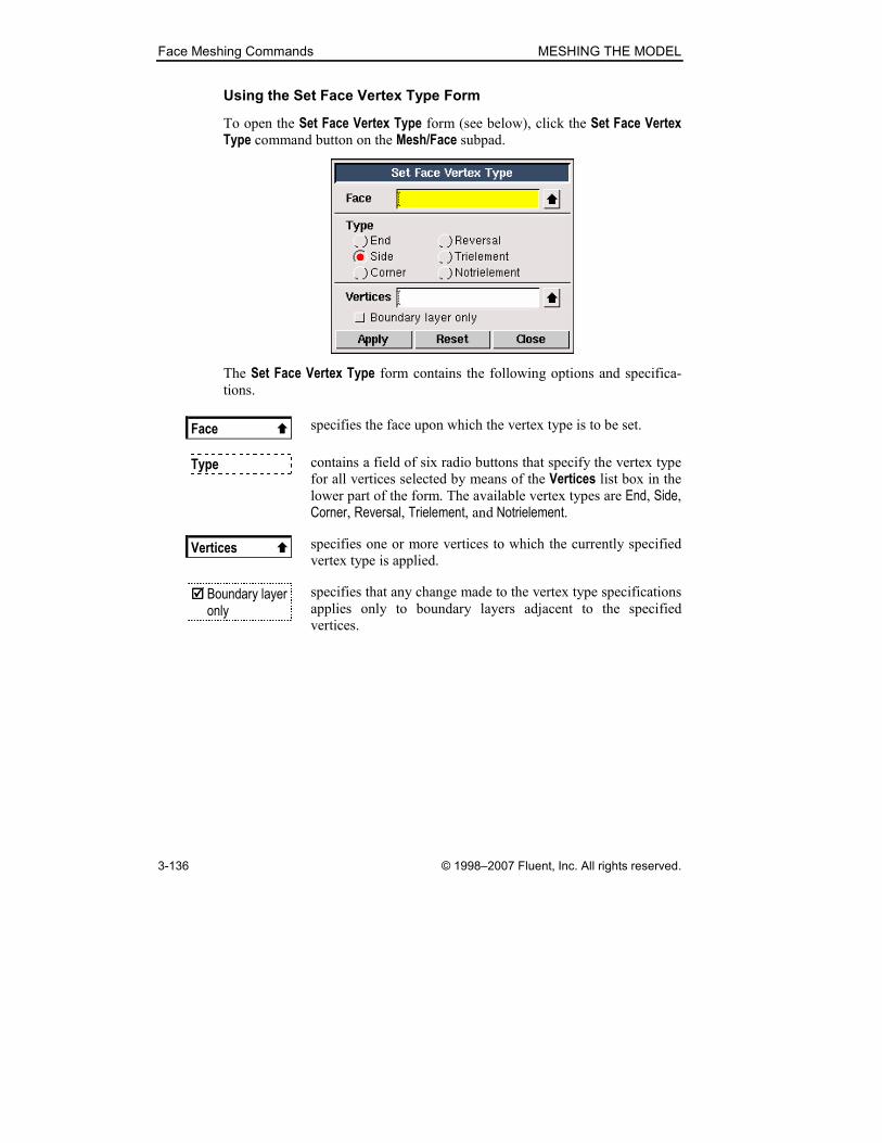
Face Meshing Commands MESHING THE MODEL
3-136 © 1998–2007 Fluent, Inc. All rights reserved.
Using the Set Face Vertex Type Form
To open the Set Face Vertex Type form (see below), click the Set Face Vertex Type command button on the Mesh/Face subpad.
The Set Face Vertex Type form contains the following options and specifica-
tions.
Face � specifies the face upon which the vertex type is to be set.
Type contains a field of six radio buttons that specify the vertex type
for all vertices selected by means of the Vertices list box in the lower part of the form. The available vertex types are End, Side, Corner, Reversal, Trielement, and Notrielement.
Vertices � specifies one or more vertices to which the currently specified
vertex type is applied.
���� Boundary layer only
specifies that any change made to the vertex type specifications
applies only to boundary layers adjacent to the specified
vertices.
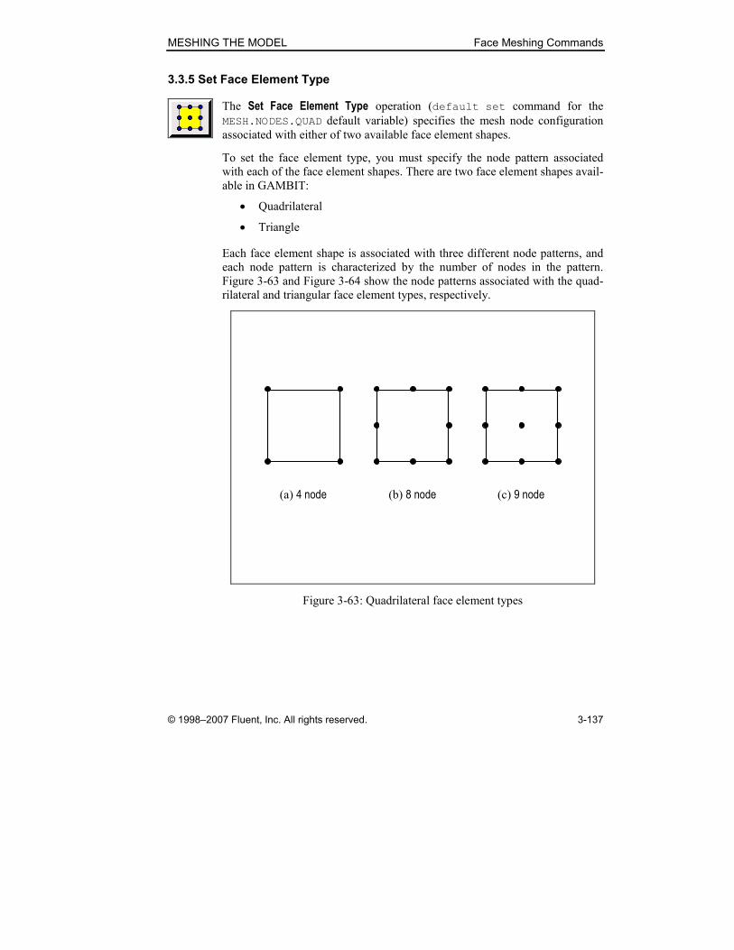
MESHING THE MODEL Face Meshing Commands
© 1998–2007 Fluent, Inc. All rights reserved. 3-137
3.3.5 Set Face Element Type
The Set Face Element Type operation (default set command for the
MESH.NODES.QUAD default variable) specifies the mesh node configuration
associated with either of two available face element shapes.
To set the face element type, you must specify the node pattern associated
with each of the face element shapes. There are two face element shapes avail-
able in GAMBIT:
• Quadrilateral
• Triangle
Each face element shape is associated with three different node patterns, and
each node pattern is characterized by the number of nodes in the pattern.
Figure 3-63 and Figure 3-64 show the node patterns associated with the quad-
rilateral and triangular face element types, respectively.
(a) 4 node (c) 9 node(b) 8 node
Figure 3-63: Quadrilateral face element types
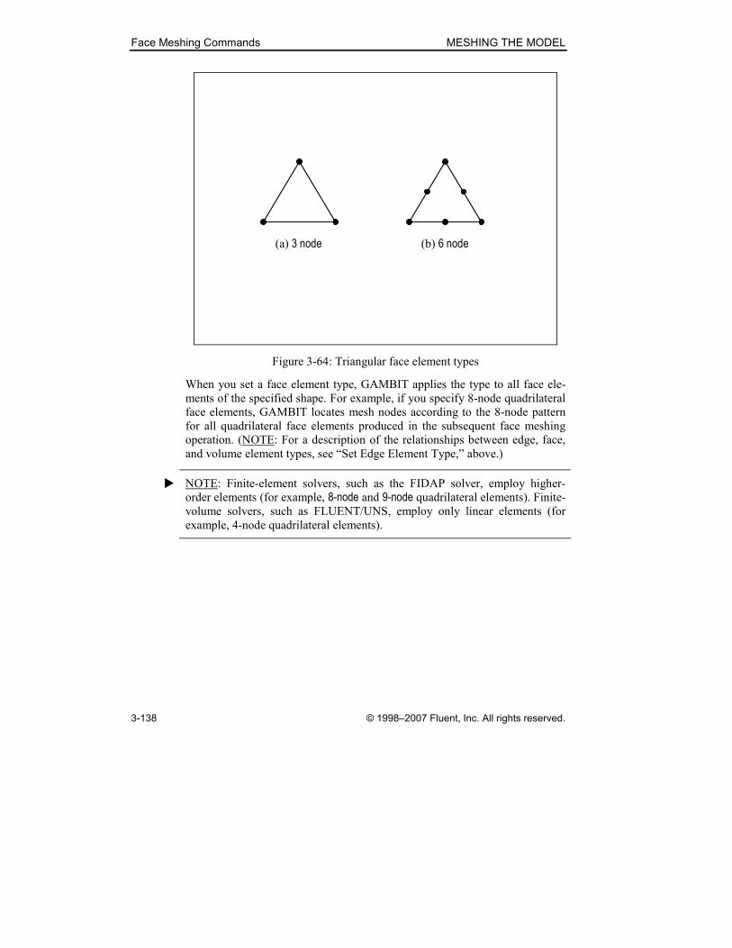
Face Meshing Commands MESHING THE MODEL
3-138 © 1998–2007 Fluent, Inc. All rights reserved.
(a) 3 node (b) 6 node
Figure 3-64: Triangular face element types
When you set a face element type, GAMBIT applies the type to all face ele-
ments of the specified shape. For example, if you specify 8-node quadrilateral
face elements, GAMBIT locates mesh nodes according to the 8-node pattern
for all quadrilateral face elements produced in the subsequent face meshing
operation. (NOTE: For a description of the relationships between edge, face,
and volume element types, see “Set Edge Element Type,” above.)
� NOTE: Finite-element solvers, such as the FIDAP solver, employ higher-
order elements (for example, 8-node and 9-node quadrilateral elements). Finite-
volume solvers, such as FLUENT/UNS, employ only linear elements (for
example, 4-node quadrilateral elements).

MESHING THE MODEL Face Meshing Commands
© 1998–2007 Fluent, Inc. All rights reserved. 3-139
Using the Set Face Element Type Form
To open the Set Face Element Type form (see below), click the Set Face Ele-ment Type command button on the Mesh/Face subpad.
The Set Face Element Type form contains the following specifications.
Quadrilateral allows you to specify the quadrilateral face element node
pattern. The available node patterns include 4 node, 8 node, and 9 node.
Triangle allows you to specify the triangular face element node pattern.
The available node patterns include 3 node and 6 node.
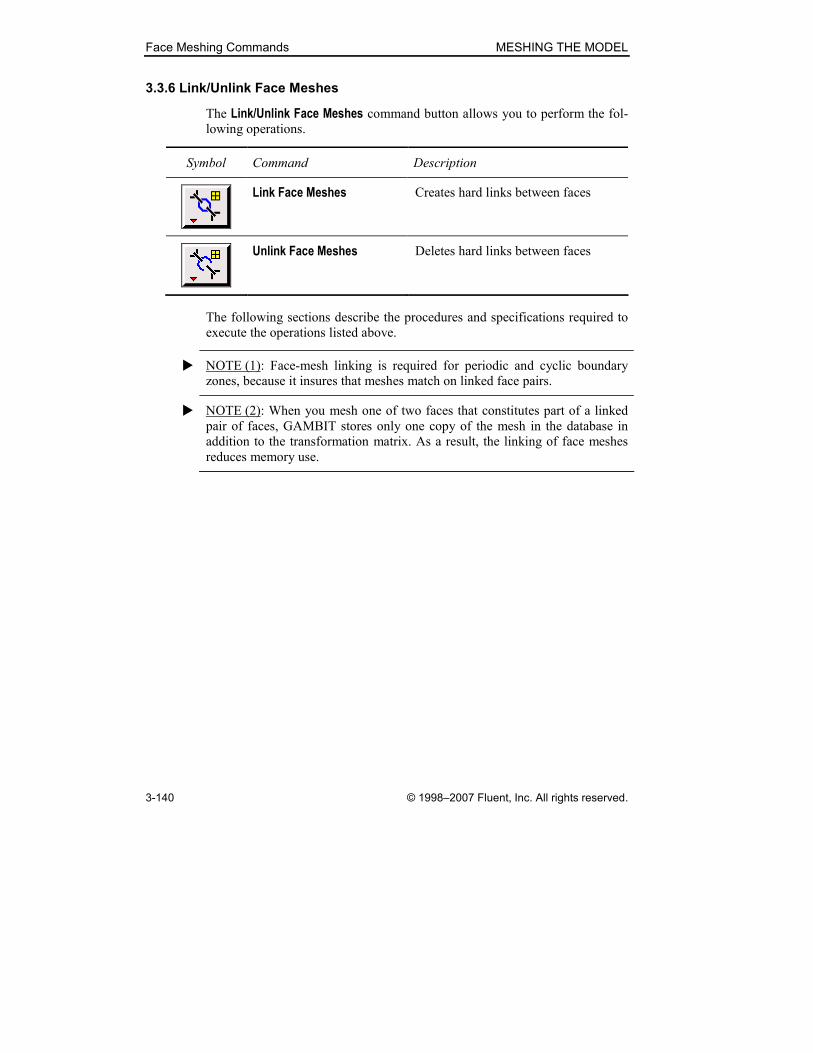
Face Meshing Commands MESHING THE MODEL
3-140 © 1998–2007 Fluent, Inc. All rights reserved.
3.3.6 Link/Unlink Face Meshes
The Link/Unlink Face Meshes command button allows you to perform the fol-
lowing operations.
Symbol Command Description
Link Face Meshes Creates hard links between faces
Unlink Face Meshes Deletes hard links between faces
The following sections describe the procedures and specifications required to
execute the operations listed above.
� NOTE (1): Face-mesh linking is required for periodic and cyclic boundary
zones, because it insures that meshes match on linked face pairs.
� NOTE (2): When you mesh one of two faces that constitutes part of a linked
pair of faces, GAMBIT stores only one copy of the mesh in the database in
addition to the transformation matrix. As a result, the linking of face meshes
reduces memory use.

MESHING THE MODEL Face Meshing Commands
© 1998–2007 Fluent, Inc. All rights reserved. 3-141
Link Face Meshes
The Link Face Meshes operation (face link command) creates a mesh hard
link between two faces. When you create hard links between faces in a set,
GAMBIT associates the faces with each other such that any meshing or split-
ting operation applied to one or more of the faces is similarly applied to all
faces in the set. For example, if you mesh a face that is hard-linked to another
face, GAMBIT meshes both faces according to the grading scheme and
parameters applied to the specified face. Likewise, if you split a boundary
edge of a face that is hard-linked to another face, GAMBIT splits the corres-
ponding edge on the other face.
� NOTE: When you select a face for the Link Face Meshes operation, GAMBIT
automatically highlights the graphic display of any faces to which the face is
currently linked.
To create a mesh hard-link between two faces, you must specify the following
parameters for each face:
• The face to be hard-linked
• A vertex that serves as a reference point for the face mesh
• The orientation of the mesh on the linked face relative to its edge loop
sense
• Whether or not the faces are periodically linked
Specifying Faces
When you hard-link two faces, the faces to be hard-linked must possess
identical numbers of edges. In addition, if a face possesses more than one
edge loop, any face to which it is hard-linked must possess an identical num-
ber of edge loops, and the edge loops that correspond to each other must pos-
sess identical numbers of edges.
As an example of this restriction, consider the six faces shown in Figure 3-65.
Of all possible combinations represented by the faces in the figure, only the
following faces may be hard-linked to each other:
• face.1 and face.2
• face.4 and face.5
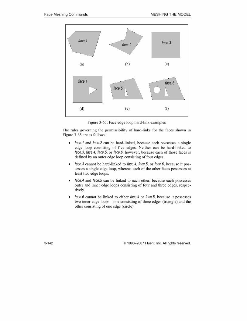
Face Meshing Commands MESHING THE MODEL
3-142 © 1998–2007 Fluent, Inc. All rights reserved.
(a) (b) (c)
(d) (e) (f)
face.1face.3
face.2
face.4 face.6
face.5
Figure 3-65: Face edge loop hard-link examples
The rules governing the permissibility of hard-links for the faces shown in
Figure 3-65 are as follows.
• face.1 and face.2 can be hard-linked, because each possesses a single edge loop consisting of five edges. Neither can be hard-linked to
face.3, face.4, face.5, or face.6, however, because each of those faces is defined by an outer edge loop consisting of four edges.
• face.3 cannot be hard-linked to face.4, face.5, or face.6, because it pos-sesses a single edge loop, whereas each of the other faces possesses at
least two edge loops.
• face.4 and face.5 can be linked to each other, because each possesses outer and inner edge loops consisting of four and three edges, respec-
tively.
• face.6 cannot be linked to either face.4 or face.5, because it possesses two inner edge loops—one consisting of three edges (triangle) and the
other consisting of one edge (circle).
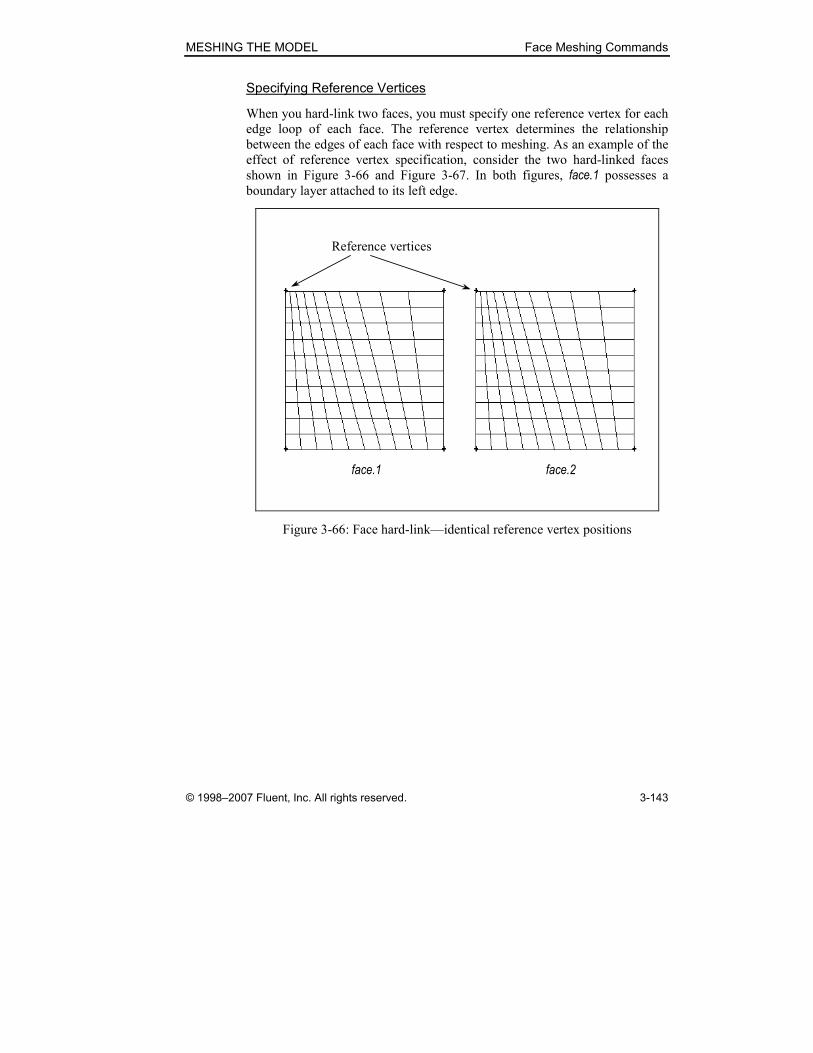
MESHING THE MODEL Face Meshing Commands
© 1998–2007 Fluent, Inc. All rights reserved. 3-143
Specifying Reference Vertices
When you hard-link two faces, you must specify one reference vertex for each
edge loop of each face. The reference vertex determines the relationship
between the edges of each face with respect to meshing. As an example of the
effect of reference vertex specification, consider the two hard-linked faces
shown in Figure 3-66 and Figure 3-67. In both figures, face.1 possesses a boundary layer attached to its left edge.
face.1 face.2
Reference vertices
Figure 3-66: Face hard-link—identical reference vertex positions
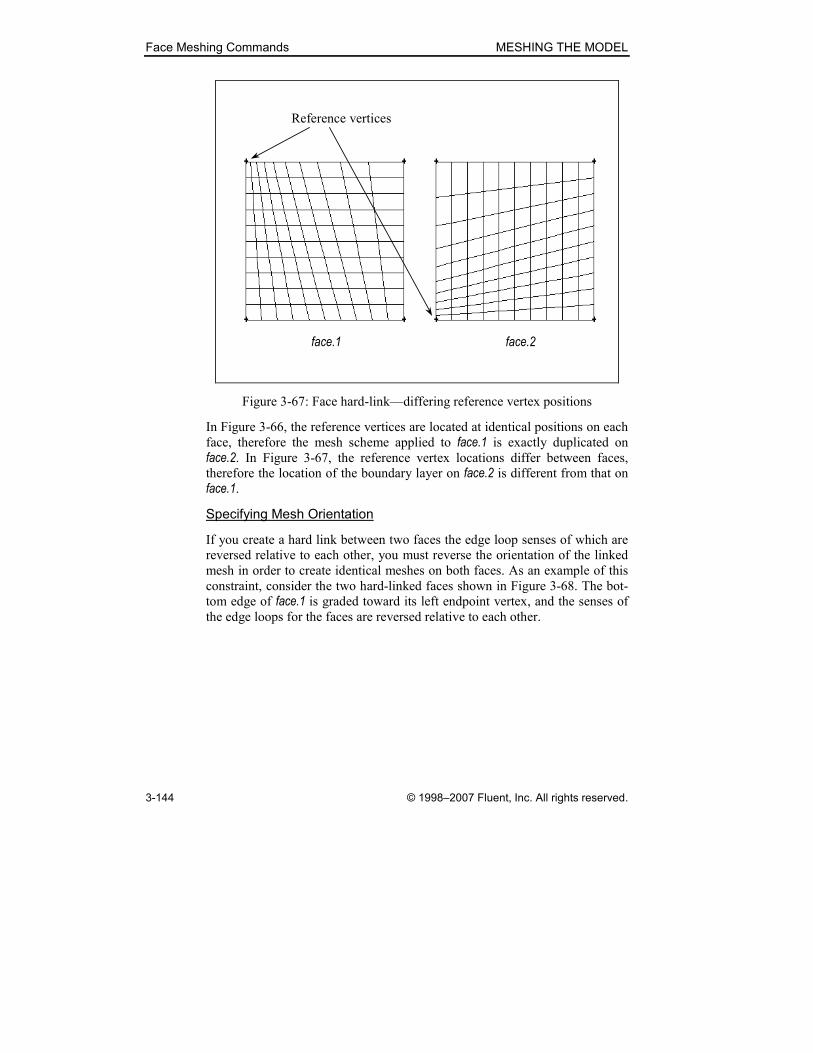
Face Meshing Commands MESHING THE MODEL
3-144 © 1998–2007 Fluent, Inc. All rights reserved.
face.1 face.2
Reference vertices
Figure 3-67: Face hard-link—differing reference vertex positions
In Figure 3-66, the reference vertices are located at identical positions on each
face, therefore the mesh scheme applied to face.1 is exactly duplicated on face.2. In Figure 3-67, the reference vertex locations differ between faces, therefore the location of the boundary layer on face.2 is different from that on
face.1.
Specifying Mesh Orientation
If you create a hard link between two faces the edge loop senses of which are
reversed relative to each other, you must reverse the orientation of the linked
mesh in order to create identical meshes on both faces. As an example of this
constraint, consider the two hard-linked faces shown in Figure 3-68. The bot-
tom edge of face.1 is graded toward its left endpoint vertex, and the senses of the edge loops for the faces are reversed relative to each other.

MESHING THE MODEL Face Meshing Commands
© 1998–2007 Fluent, Inc. All rights reserved. 3-145
face.1 face.2
Reference vertices Edge sense
Figure 3-68: Face hard-link—orientation relative to edge loop sense
If you specify reference vertices at identical positions on both faces, GAMBIT
constructs a mesh on the linked face (for example, face.2) that is different in orientation from that constructed on the specified face (for example, face.1). To create identical meshes on both faces when you specify reference vertices
as shown in Figure 3-68, you must specify the Reverse orientation option when you create the mesh hard link.
Specifying the Periodic Option
The Link Face Meshes command includes a Periodic option that allows you to specify that the faces are periodically linked. Periodically linked faces are
constrained such that they must behave identically to each other with respect
to any virtual edge-split and vertex-move operations. For a general description
of the effect of periodic linking on the boundary edges of periodically linked
faces, see “Link Edge Meshes,” in Section 3.2.3, above.

Face Meshing Commands MESHING THE MODEL
3-146 © 1998–2007 Fluent, Inc. All rights reserved.
Using the Link Face Meshes Form
To open the Link Face Meshes form (see below), click the Link command but-
ton on the Mesh/Face subpad.
The Link Face Meshes form contains the following specifications.
Face � specifies the first of two faces to be hard-linked.
Vertices � specifies one or more reference vertices on the first of the hard-
linked faces. (NOTE: You must specify one reference vertex
for each edge loop associated with the face.)
Link With —————————————————————————
Face � specifies the second of two faces to be hard-linked.
Vertices � specifies one or more reference vertices on the second hard-
linked face (see above).
���� Reverse orientation
specifies that the edge meshing on the second of the two hard-
linked faces is reversed relative to the first.
���� Periodic specifies that the faces are to be periodically linked.
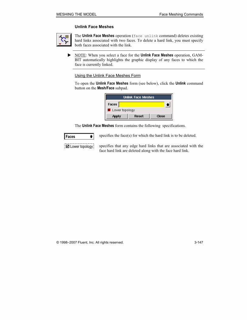
MESHING THE MODEL Face Meshing Commands
© 1998–2007 Fluent, Inc. All rights reserved. 3-147
Unlink Face Meshes
The Unlink Face Meshes operation (face unlink command) deletes existing
hard links associated with two faces. To delete a hard link, you must specify
both faces associated with the link.
� NOTE: When you select a face for the Unlink Face Meshes operation, GAM-
BIT automatically highlights the graphic display of any faces to which the
face is currently linked.
Using the Unlink Face Meshes Form
To open the Unlink Face Meshes form (see below), click the Unlink command
button on the Mesh/Face subpad.
The Unlink Face Meshes form contains the following specifications.
Faces � specifies the face(s) for which the hard link is to be deleted.
���� Lower topology specifies that any edge hard links that are associated with the
face hard link are deleted along with the face hard link.

Face Meshing Commands MESHING THE MODEL
3-148 © 1998–2007 Fluent, Inc. All rights reserved.
3.3.7 Modify Meshed Face / Split Meshed Face
The Modify Meshed Face / Split Meshed Face command button allows you to
perform the following operations.
Symbol Command Description
Modify Meshed Face Converts mesh edges to topological
equivalents
Split Meshed Face Splits a face along lines defined by an
existing mesh
The following sections describe each of these operations.
MESHING THE MODEL Face Meshing Commands
© 1998–2007 Fluent, Inc. All rights reserved. 3-149
Modify Meshed Face
The Modify Meshed Face operation (face split command) converts mesh
edges to faceted topological edges and creates faceted faces where appro-
priate. The command can be used to create faceted representations of existing
geometry or to modify geometry associated with imported mesh information.
To perform a Modify Meshed Face operation, you must first create a Mesh edges conversion list—that is, a list of mesh edges that are to be converted to
faceted geometric edges. To create the conversion list, you must specify the
following parameters:
• The meshed face of interest
• The mesh edges that are to be included in the conversion list
Specifying the Meshed Face
You can specify any meshed face for a Modify Meshed Face operation. The shape of the meshed face determines which mesh edges are added to the con-
version list when using the automatic method of mesh-edge specification (see
below).
Specifying the Mesh Edges
GAMBIT provides two methods for adding mesh edges to the Mesh edges conversion list:
• Automatic
• Manual
When you use the automatic method, GAMBIT automatically adds mesh
edges to the conversion list based on the angle between the outward-pointing
normals of any two adjacent mesh element faces. When you use the manual
method, GAMBIT allows you to select specific mesh edges to be added to (or
removed from) the list.
� NOTE (1): To activate the Mesh edges conversion-list picker, you must first
select a meshed face and Shift-right-click in the graphics window to accept the
selection.
� NOTE (2): When you perform a Modify Meshed Face operation, GAMBIT
highlights mesh edges in the graphics window according to the following
default color code:
• Pink—Detected/picked mesh edges
• Light blue—Undetected/unpicked mesh edges

Face Meshing Commands MESHING THE MODEL
3-150 © 1998–2007 Fluent, Inc. All rights reserved.
Using the Automatic Method
To employ the automatic method of adding mesh edges to the conversion list,
you must specify an Angle parameter, θmin
. The Angle parameter represents
the minimum angle (in degrees) between outward-pointing normals for any
two faces the common edge of which is to be automatically added to the con-
version list (see Figure 3-69).
Mesh edge to be added to
the conversion list
Angle between normals
θ
Figure 3-69: Automatic-method angle criterion
When you employ the automatic method, GAMBIT applies the Angle ( minθ )
criterion to all mesh element faces associated with the meshed topological
face. If minθθ > for any two mesh element faces, GAMBIT adds their com-
mon mesh edge to the conversion list. If minθθ < , GAMBIT does not add the
mesh edge to the conversion list. If you specify Angle = 0 and employ the
automatic method for the face, GAMBIT adds to the conversion list all of the
mesh edges associated with the face.
As an example of the use of the automatic method, consider the meshed ellip-
tical, cylindrical face shown in Figure 3-70. The face is meshed using a regu-
lar map mesh with 40 intervals on each of the elliptical boundary edges,
resulting in 560 regular quadrilateral mesh elements.
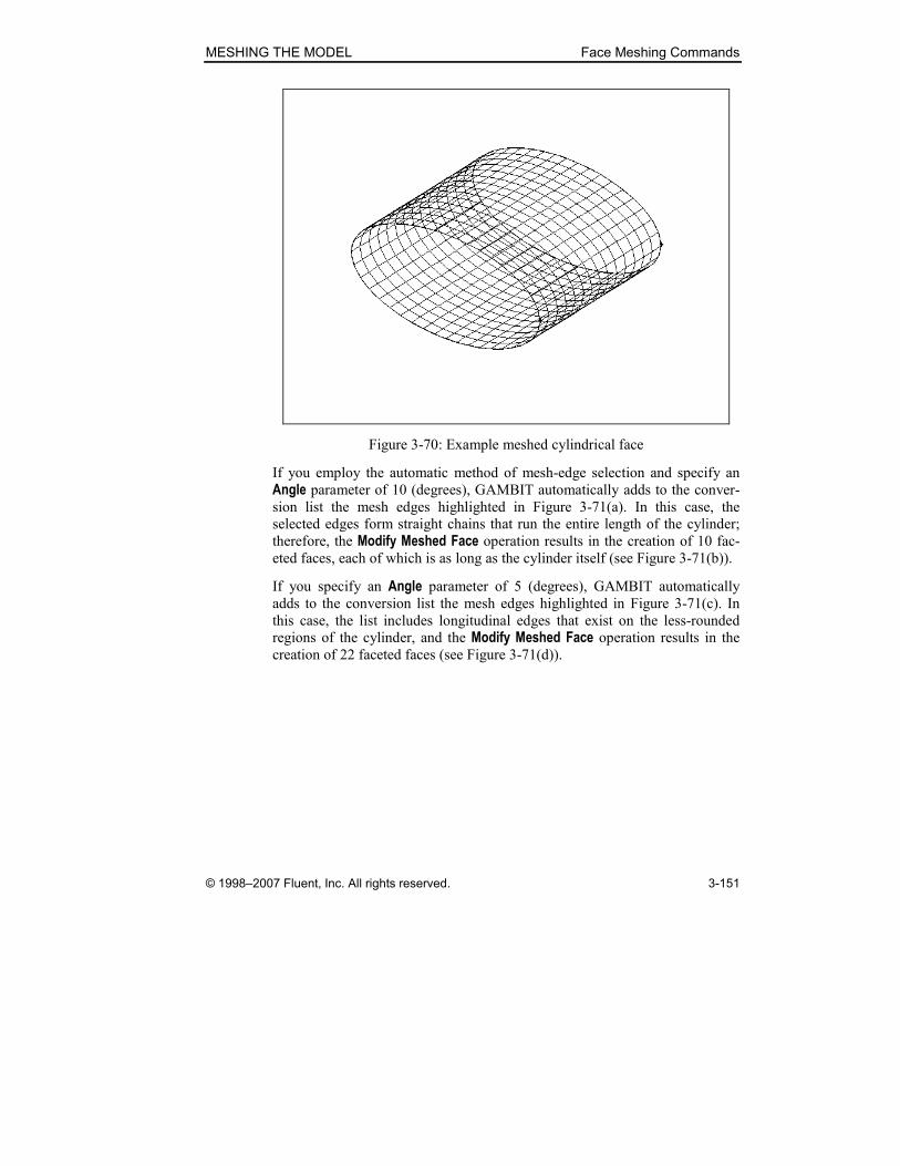
MESHING THE MODEL Face Meshing Commands
© 1998–2007 Fluent, Inc. All rights reserved. 3-151
Figure 3-70: Example meshed cylindrical face
If you employ the automatic method of mesh-edge selection and specify an
Angle parameter of 10 (degrees), GAMBIT automatically adds to the conver-
sion list the mesh edges highlighted in Figure 3-71(a). In this case, the
selected edges form straight chains that run the entire length of the cylinder;
therefore, the Modify Meshed Face operation results in the creation of 10 fac-eted faces, each of which is as long as the cylinder itself (see Figure 3-71(b)).
If you specify an Angle parameter of 5 (degrees), GAMBIT automatically
adds to the conversion list the mesh edges highlighted in Figure 3-71(c). In
this case, the list includes longitudinal edges that exist on the less-rounded
regions of the cylinder, and the Modify Meshed Face operation results in the creation of 22 faceted faces (see Figure 3-71(d)).

Face Meshing Commands MESHING THE MODEL
3-152 © 1998–2007 Fluent, Inc. All rights reserved.
(a) Selected edges, Angle = 10 (b) Created faces, Angle = 10
(c) Selected edges, Angle = 5 (d) Created faces, Angle = 5
Figure 3-71: Effect of Angle parameter on created faces
� NOTE (1): GAMBIT does not include any lateral mesh edges in this example
(that is, mesh edges that are perpendicular to the cylinder axis), because all
adjacent faces that share common lateral edges are parallel to each other.
� NOTE (2): All faces created by the Modify Meshed Face command are faceted
faces. By default, GAMBIT labels all faceted faces with the prefix “f_”—for
example, f_face.107.
� NOTE (3): When you create faceted faces by means of the Modify Meshed Face command, GAMBIT does not delete the underlying face geometry. For
example, the geometry shown in Figure 3-71(b), above, includes 10 faceted
faces, as well as the original real elliptical face.

MESHING THE MODEL Face Meshing Commands
© 1998–2007 Fluent, Inc. All rights reserved. 3-153
Using the Manual Method
When you use the manual method of managing the mesh-edge conversion list,
GAMBIT allows you to perform the following operations, each of which cor-
responds to a separate option on the Modify Meshed Face form.
• Add—Adds mesh edges to the conversion list
• Remove—Removes mesh edges from the conversion list
• Remove spurs—Removes continuous chains of mesh edges from the
conversion list
Adding and Removing Edges
To add or remove a mesh edge to or from the conversion list, you must select
the Add or Remove option, respectively, and specify the mesh edge to be added
or removed. You can specify the mesh edge to be added or removed in the
following ways:
• Input the number corresponding to the mesh edge in the Mesh edges list box.
• Pick the mesh edge in the graphics window.
� NOTE (1): The mesh edge conversion list automatically includes all mesh
edges that exist on the boundary edges of the meshed face. GAMBIT does not
allow you to remove such edges from the conversion list.
� NOTE (2): If you click the Mesh edges pick-list button, GAMBIT displays the
special Mesh Edge List (Multiple) pick-list form. The form differs from ordi-
nary pick-list forms in that it does not include a list of Available mesh edges.
(In most cases, the list of Available mesh edges is too long to be of practical
use.) Otherwise, the form operates according to the principles that govern all
pick-list forms.
Removing Spurs
Spurs are chains of connected mesh edges in the conversion list—such as
those that form the longitudinal edges of the faceted faces shown in Figure
3-71, above. Spurs that do not attach at both ends to other topological edges
constitute dangling spurs (see Figure 3-72).

Face Meshing Commands MESHING THE MODEL
3-154 © 1998–2007 Fluent, Inc. All rights reserved.
Dangling spurs
Figure 3-72: Example dangling spurs
When you select the Remove spurs option and specify a mesh edge that con-
stitutes any part of a spur, GAMBIT removes from the conversion list all
edges associated with the spur.
Combining the Automatic and Manual Methods
The Modify Meshed Face command allows you to combine the automatic and
manual methods to create the Mesh edges conversion list. For example, you
can use the automatic method to create the overall conversion list and use the
manual method to modify the list.
Figure 3-73 shows the effect of a combined automatic/manual method on the
meshed elliptical cylinder shown above. In this case, the conversion list is first
created by using the automatic method with an Angle specification of 5 (degrees) then modified using the manual method to add and remove edges
from the list as shown. Figure 3-73(b) shows the faceted faces created from
the resulting Modify Meshed Face operation.

MESHING THE MODEL Face Meshing Commands
© 1998–2007 Fluent, Inc. All rights reserved. 3-155
(a) Selected edges
(b) Created faces
Added and removed edges
Figure 3-73: Combined use of automatic and manual methods
� NOTE: To combine the automatic and manual methods, you must use the
automatic method before using the manual method. Each time you input a
value into the Angle input field (or use the Angle slider bar), GAMBIT resets
the conversion list and populates it based only on mesh edges specified using
the current Angle criterion.
Selecting the Entire Meshed Face
You can specify selection of the entire meshed face for conversion in either of
the following ways.
• Use the automatic method with an Angle specification of 0.
• Open the Mesh edges pick-list form, and click All-> to select all meshed
edges in the list.
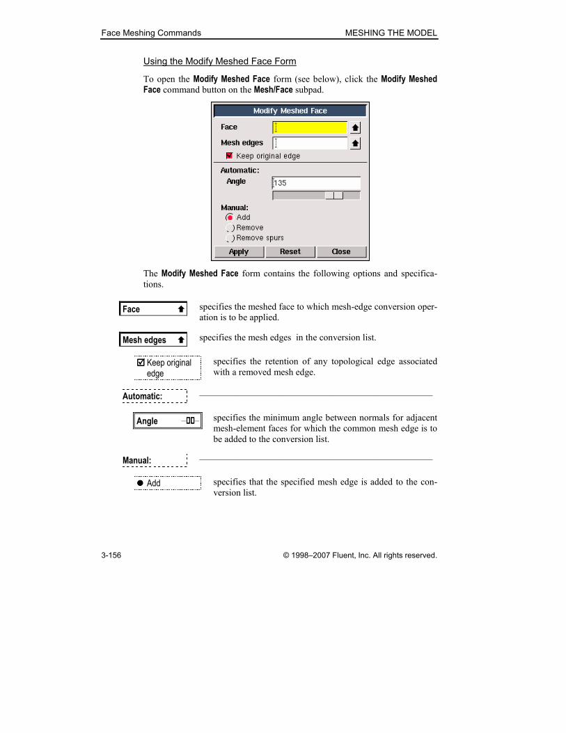
Face Meshing Commands MESHING THE MODEL
3-156 © 1998–2007 Fluent, Inc. All rights reserved.
Using the Modify Meshed Face Form
To open the Modify Meshed Face form (see below), click the Modify Meshed Face command button on the Mesh/Face subpad.
The Modify Meshed Face form contains the following options and specifica-
tions.
Face � specifies the meshed face to which mesh-edge conversion oper-
ation is to be applied.
Mesh edges � specifies the mesh edges in the conversion list.
���� Keep original edge
specifies the retention of any topological edge associated
with a removed mesh edge.
Automatic: —————————————————————————
Angle –��������– specifies the minimum angle between normals for adjacent
mesh-element faces for which the common mesh edge is to
be added to the conversion list.
Manual: —————————————————————————
���� Add specifies that the specified mesh edge is added to the con-
version list.

MESHING THE MODEL Face Meshing Commands
© 1998–2007 Fluent, Inc. All rights reserved. 3-157
���� Remove specifies that the specified mesh edge is removed from the
conversion list.
���� Remove spurs specifies that all edges included in the spur associated with
the specified mesh edge are removed from the conversion
list.
Face Meshing Commands MESHING THE MODEL
3-158 © 1998–2007 Fluent, Inc. All rights reserved.
Split Meshed Face
The Split Meshed Face operation (face split command) splits a meshed
face into two virtual faces.
When you split a face by means of the Split Meshed Face command, GAMBIT
creates two virtual faces that share a common virtual edge. The shape of the
virtual edge is determined by the nodes that define the split path. Once the
virtual faces are created, GAMBIT retains them even if you delete the mesh
that was used to define their shapes.
To split a meshed face by means of the Split Meshed Face command, you must
specify the following parameters.
• The meshed face to be split
• The mesh nodes that define the split path
• The Split edge angle option
Specifying the Face
You can use the Split Meshed Face command to split any real or virtual face
that is currently meshed.
Specifying the Split Path Mesh Nodes
To split a face using mesh nodes, you must specify two or more mesh nodes
that define the path of the split. Two of the mesh nodes must be located on the
edges of the face. The other mesh nodes that define the split path may exist
anywhere else internal to the face, but none of them may lie on one of the
edges of the face.
Figure 3-74 illustrates the effect of splitting a real face by means of the Split Meshed Face form. Figure 3-74(a) shows the mesh and four mesh nodes that
define the split path. Figure 3-74(b) shows the two virtual faces that result
from the split operation.
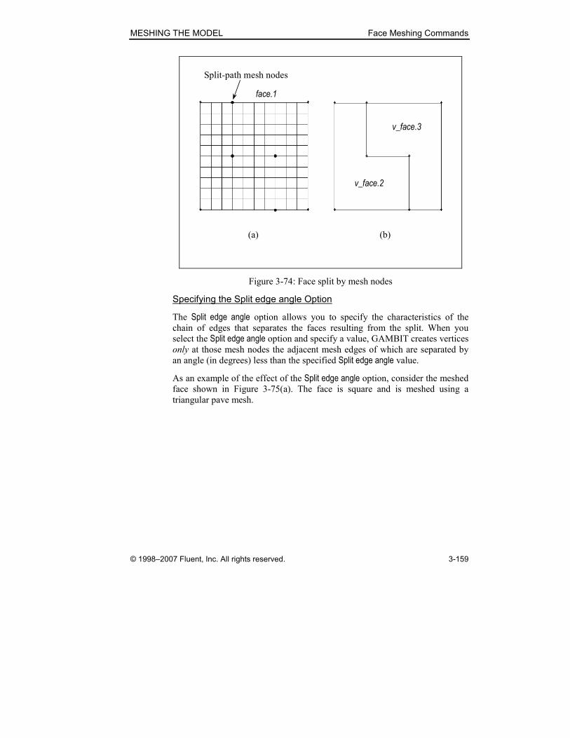
MESHING THE MODEL Face Meshing Commands
© 1998–2007 Fluent, Inc. All rights reserved. 3-159
Split-path mesh nodes
(a) (b)
face.1
v_face.2
v_face.3
Figure 3-74: Face split by mesh nodes
Specifying the Split edge angle Option
The Split edge angle option allows you to specify the characteristics of the chain of edges that separates the faces resulting from the split. When you
select the Split edge angle option and specify a value, GAMBIT creates vertices
only at those mesh nodes the adjacent mesh edges of which are separated by
an angle (in degrees) less than the specified Split edge angle value.
As an example of the effect of the Split edge angle option, consider the meshed
face shown in Figure 3-75(a). The face is square and is meshed using a
triangular pave mesh.

Face Meshing Commands MESHING THE MODEL
3-160 © 1998–2007 Fluent, Inc. All rights reserved.
(b) Split edge angle off(a) Original meshed face
(c) Split edge angle = 140º (d) Split edge angle = 90º
Splitting
nodesv_face.2
v_face.3
v_face.2
v_face.3v_face.2
v_face.3
Figure 3-75: Effect of Split edge angle option
If you split the face and do not specify the Split edge angle option, GAMBIT
creates vertices at each mesh node along the split path and joins the vertices
with a chain of straight edges that splits the face (Figure 3-75(b)). If you spec-
ify a Split edge angle value of 140, GAMBIT creates vertices only at those
nodes the adjacent mesh edges of which are separated by an angle less than
140º (Figure 3-75(c)). If you specify a Split edge angle value of 90, GAMBIT
splits the meshed face with a single edge (Figure 3-75(d)).
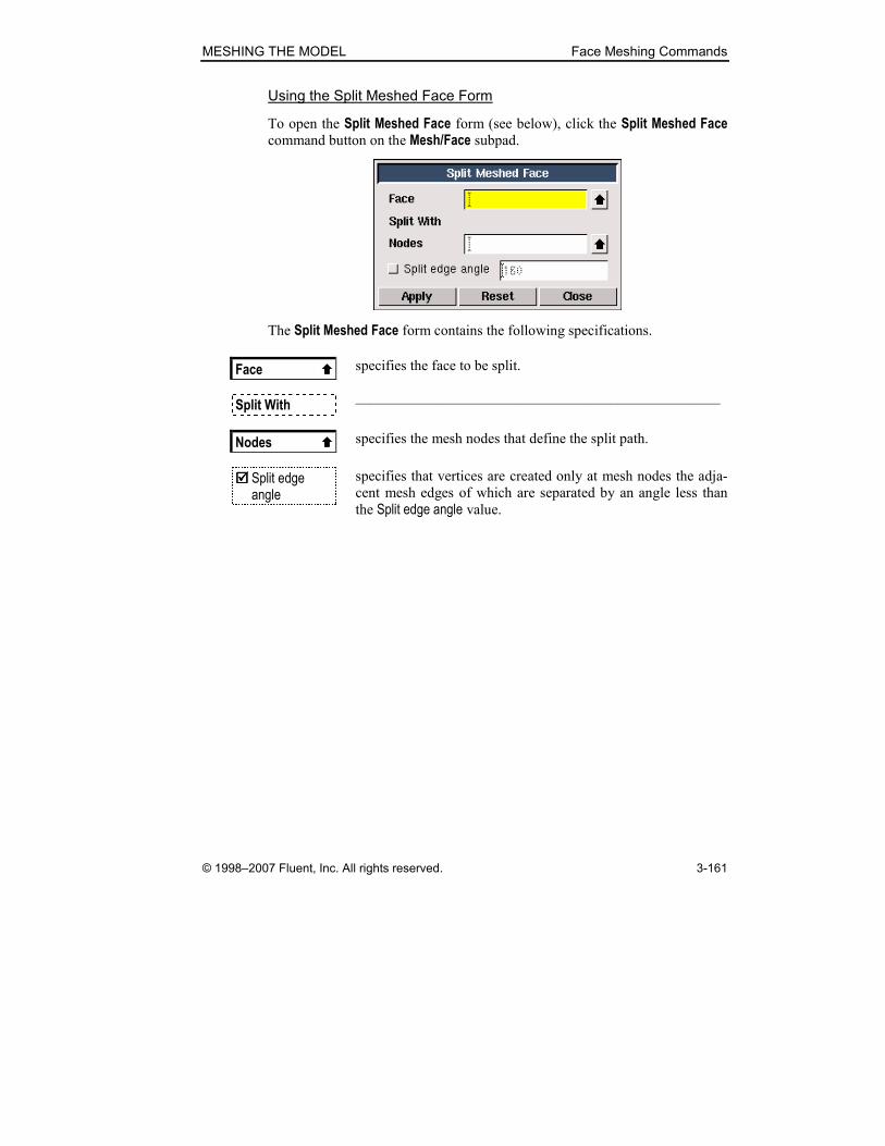
MESHING THE MODEL Face Meshing Commands
© 1998–2007 Fluent, Inc. All rights reserved. 3-161
Using the Split Meshed Face Form
To open the Split Meshed Face form (see below), click the Split Meshed Face command button on the Mesh/Face subpad.
The Split Meshed Face form contains the following specifications.
Face � specifies the face to be split.
Split With —————————————————————————
Nodes � specifies the mesh nodes that define the split path.
���� Split edge angle
specifies that vertices are created only at mesh nodes the adja-
cent mesh edges of which are separated by an angle less than
the Split edge angle value.

Face Meshing Commands MESHING THE MODEL
3-162 © 1998–2007 Fluent, Inc. All rights reserved.
3.3.8 Summarize/Check Face Meshes
The Summarize/Check Face Meshes command button lets you perform the
following operations.
Symbol Command Description
Summarize Face Mesh Summarizes general face mesh infor-
mation in the Transcript window
Check Face Meshes Displays face mesh quality informa-
tion in the Transcript window
The following sections describe the procedures and specifications required to
execute the operations listed above.

MESHING THE MODEL Face Meshing Commands
© 1998–2007 Fluent, Inc. All rights reserved. 3-163
Summarize Face Mesh
The Summarize Face Mesh operation (face msummarize command) dis-
plays face mesh information in the Transcript window and allows you to highlight specific mesh nodes and/or mesh elements in the graphics window.
The command requires three input parameters:
• Face for which the mesh is to be summarized
• Type of component (elements or nodes) to be summarized
• Specific components to be included in the summary
Specifying the Component Type
To summarize face mesh information in the Transcript window, you must
specify the type of mesh components to be included in the summary. Each
face mesh includes two component types:
• Elements
• Nodes
The type of mesh summary information displayed in the Transcript window depends on the component type (see “Face Mesh Summary Information,”
below).
Selecting Specific Components
GAMBIT provides two methods for selecting specific components (elements
or nodes) to be included in the face mesh summary:
• Picking the components in the graphics window
• Selecting the components by means of a pick list
In most cases, it is preferable to pick the components in the graphics window,
rather than selecting them by means of a pick list, because the component
labels (element or node numbers) are not known prior to component selection.
To pick the components in the graphics window:
1. Select the appropriate Component option (Elements or Nodes).
2. Click (to activate) the appropriate (Elements or Nodes) pick-list field.
3. Shift-left-click in the graphics window to select each element or node
to be included in the summary.

Face Meshing Commands MESHING THE MODEL
3-164 © 1998–2007 Fluent, Inc. All rights reserved.
To select the components by means of a pick list:
1. Select the appropriate Component option (Elements or Nodes).
2. Click the appropriate (Elements or Nodes) pick-list button to open the Mesh Face List (Multiple) or Mesh Node List (Multiple) form.
3. On the Mesh Face List (Multiple) or Mesh Node List (Multiple) form,
click the All–> pushbutton to populate the list with all elements or
nodes associated with the specified face.
4. In the Mesh Face List (Multiple) or Mesh Node List (Multiple) list, select (highlight) the elements or nodes to be excluded from the summary.
5. Click the <– – – pushbutton to remove the selected (highlighted) ele-
ments or nodes from the list.
� NOTE: The Mesh Face List (Multiple) and Mesh Node List (Multiple) forms do
not include the Available list field that is included on most pick-list forms
because of the number of items that might need to be included in the list field.
A fully meshed model can contain tens of thousands of mesh elements or
nodes, each of which constitutes an Available component. If the Mesh Face List (Multiple) or Mesh Node List (Multiple) form included an Available list field, GAMBIT would need to compile the Available list before opening the form,
thereby delaying the appearance of the form on the GUI.
When you specify any component (element or node) to be included in the
mesh summary, GAMBIT highlights the component in the graphics window.
If you select the Element labels and/or Node labels options, GAMBIT also dis-
plays the element and/or node numbers associated with the specified compo-
nents (see Figure 3-76).

MESHING THE MODEL Face Meshing Commands
© 1998–2007 Fluent, Inc. All rights reserved. 3-165
Node numbers Element
numbers
Figure 3-76: Face mesh element and node numbering display
Face Mesh Summary Information
As noted above, the type of mesh summary information displayed in the
Transcript window depends on the type of component being summarized. For
example, element summaries include node connectivity information, which is
not available in node summaries.
Elements Summary Information
If you select the Elements option, the mesh summary includes the following
information for each specified element.
• Element number
• Element type
• Number (count) of nodes associated with the element
• Connectivity of nodes associated with the element
For example, if you select an Elements summary for the face and highlighted
elements shown in Figure 3-76, above, GAMBIT displays the following infor-
mation in the Transcript window.
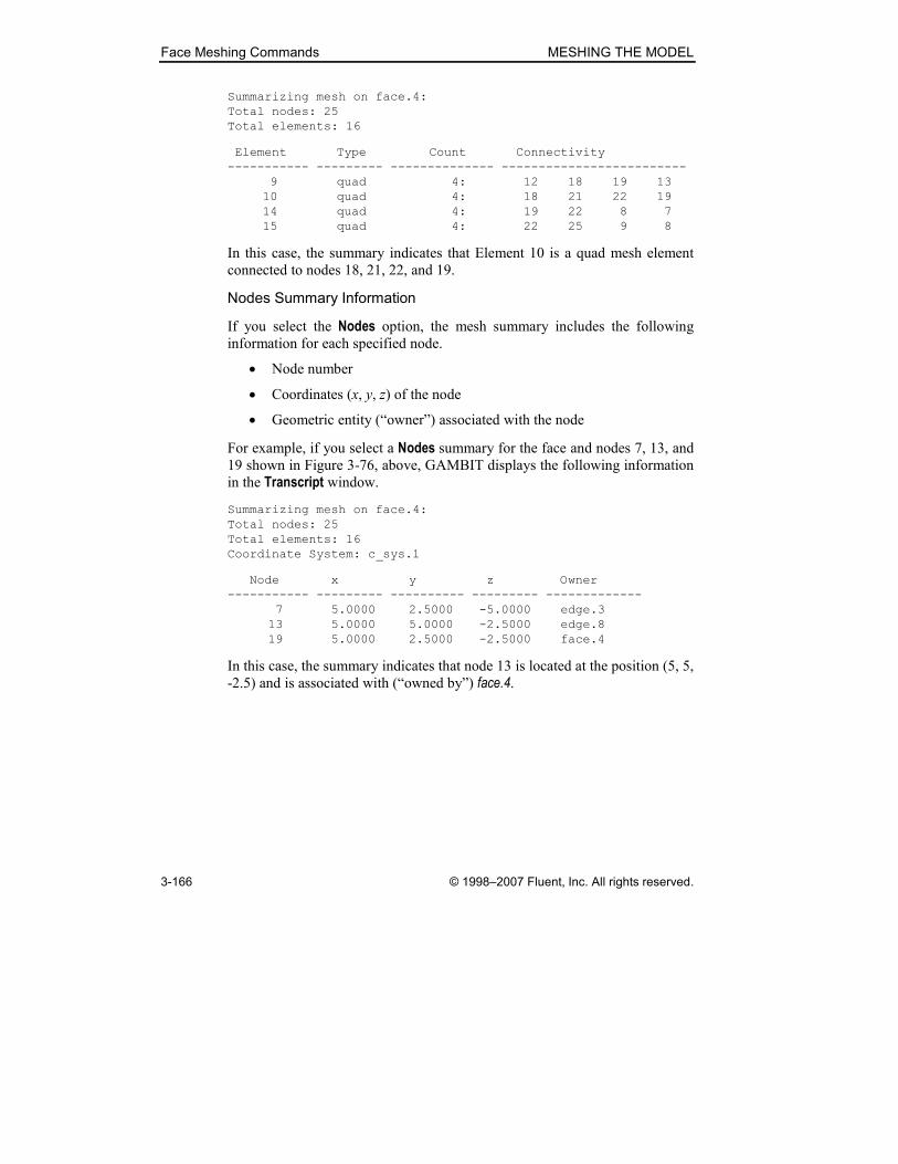
Face Meshing Commands MESHING THE MODEL
3-166 © 1998–2007 Fluent, Inc. All rights reserved.
Summarizing mesh on face.4:
Total nodes: 25
Total elements: 16
Element Type Count Connectivity
----------- --------- -------------- -------------------------
9 quad 4: 12 18 19 13
10 quad 4: 18 21 22 19
14 quad 4: 19 22 8 7
15 quad 4: 22 25 9 8
In this case, the summary indicates that Element 10 is a quad mesh element
connected to nodes 18, 21, 22, and 19.
Nodes Summary Information
If you select the Nodes option, the mesh summary includes the following
information for each specified node.
• Node number
• Coordinates (x, y, z) of the node
• Geometric entity (“owner”) associated with the node
For example, if you select a Nodes summary for the face and nodes 7, 13, and
19 shown in Figure 3-76, above, GAMBIT displays the following information
in the Transcript window.
Summarizing mesh on face.4:
Total nodes: 25
Total elements: 16
Coordinate System: c_sys.1
Node x y z Owner
----------- --------- ---------- --------- -------------
7 5.0000 2.5000 -5.0000 edge.3
13 5.0000 5.0000 -2.5000 edge.8
19 5.0000 2.5000 -2.5000 face.4
In this case, the summary indicates that node 13 is located at the position (5, 5,
-2.5) and is associated with (“owned by”) face.4.
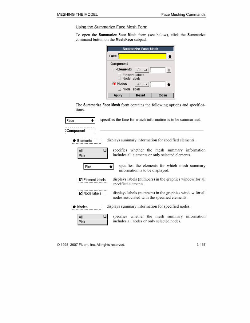
MESHING THE MODEL Face Meshing Commands
© 1998–2007 Fluent, Inc. All rights reserved. 3-167
Using the Summarize Face Mesh Form
To open the Summarize Face Mesh form (see below), click the Summarize command button on the Mesh/Face subpad.
The Summarize Face Mesh form contains the following options and specifica-
tions.
Face � specifies the face for which information is to be summarized.
Component —————————————————————————
���� Elements displays summary information for specified elements.
All � Pick
specifies whether the mesh summary information
includes all elements or only selected elements.
Pick � specifies the elements for which mesh summary
information is to be displayed.
���� Element labels displays labels (numbers) in the graphics window for all
specified elements.
���� Node labels displays labels (numbers) in the graphics window for all
nodes associated with the specified elements.
���� Nodes displays summary information for specified nodes.
All � Pick
specifies whether the mesh summary information
includes all nodes or only selected nodes.

Face Meshing Commands MESHING THE MODEL
3-168 © 1998–2007 Fluent, Inc. All rights reserved.
Pick � specifies the nodes for which mesh summary infor-
mation is to be displayed.
���� Node labels displays labels (numbers) in the graphics window for all
specified nodes.

MESHING THE MODEL Face Meshing Commands
© 1998–2007 Fluent, Inc. All rights reserved. 3-169
Check Face Meshes
The Check Face Meshes operation (face check quality command) dis-
plays 2-D mesh quality data. When you execute the Check Face Meshes com-
mand, GAMBIT displays the following elements in the Transcript window:
• A table that summarizes 2-D mesh quality statistical information for
all faces specified on the Check Face Meshes form
• A summary statement that includes the total number of inverted mesh
elements and the number of specified faces that contain inverted
elements
Tabular 2-D Mesh Quality Data
The Check Face Meshes tabular output represents the statistical distribution of element quality values for the current default 2-D quality metric. Table 3.1
shows an example of such output for a face mesh evaluated according to the
EquiAngle Skew quality metric. Output such as that shown in Table 3.1 consti-
tutes a numerical representation of the mesh quality histogram that is dis-
played on the Examine Mesh form when you choose the Display Type:Range option (see Section 3.4.2 of the GAMBIT User’s Guide).
Table 3.1: Example Check Face Meshes tabular output
From value To value Count in range % of total count (114)
-------------------------------------------------------------
0 0.1 36 31.58
0.1 0.2 46 40.35
0.2 0.3 20 17.54
0.3 0.4 6 5.26
0.4 0.5 2 1.75
0.5 0.6 4 3.51
0.6 0.7 0 0.00
0.7 0.8 0 0.00
0.8 0.9 0 0.00
0.9 1 0 0.00
-------------------------------------------------------------
0 1 114 100.00
In addition to the tabular output shown in Table 3.1, the Check Face Meshes command displays the minimum and maximum values of element quality for
the set of specified faces, thus:
Measured minimum value: 0.0286973
Measured maximum value: 0.587398
Face Meshing Commands MESHING THE MODEL
3-170 © 1998–2007 Fluent, Inc. All rights reserved.
This minimum and maximum element quality information is not available by
means of any other GAMBIT operation.
Specifying the Quality Metric
As noted above, the Check Face Meshes command evaluates 2-D mesh ele-
ment quality according to the current default mesh quality metric. To change
the metric used to evaluate element quality for the Check Face Meshes command, you must modify the default 2-D mesh quality metric by means of
the Edit Defaults form. To do so:
1. Open the Edit Defaults form.
2. Click the MESH tab to open the MESH defaults subform.
3. Select the EXAMINE radio button to display the EXAMINE variables.
4. Modify the ELEMENT_2D_QUALITY variable.
(For a complete description of the procedures required to modify default vari-
ables by means of the Edit Defaults form, see Section 4.2.4 of the GAMBIT
User’s Guide.)
For example, to evaluate 2-D elements on the basis of the Aspect Ratio metric:
1. Use the procedure described above to set Aspect Ratio as the default
quality metric (ELEMENT_2D_QUALITY=2 )
2. Execute the Check Face Meshes command.
� NOTE: Check Face Meshes command tabular output, such as that shown in
Table 3.1, above, includes all 2-D elements that possess shapes for which the
current default quality metric applies. For example, if you specify Aspect Ratio as the default quality metric, the tabular output includes all quadrilateral and
triangular elements associated with the faces specified on the Check Face Meshes form. However, if you specify Diagonal Ratio as the default quality metric, the tabular output includes only quadrilateral elements, because the
Diagonal Ratio metric does not apply to triangular elements.
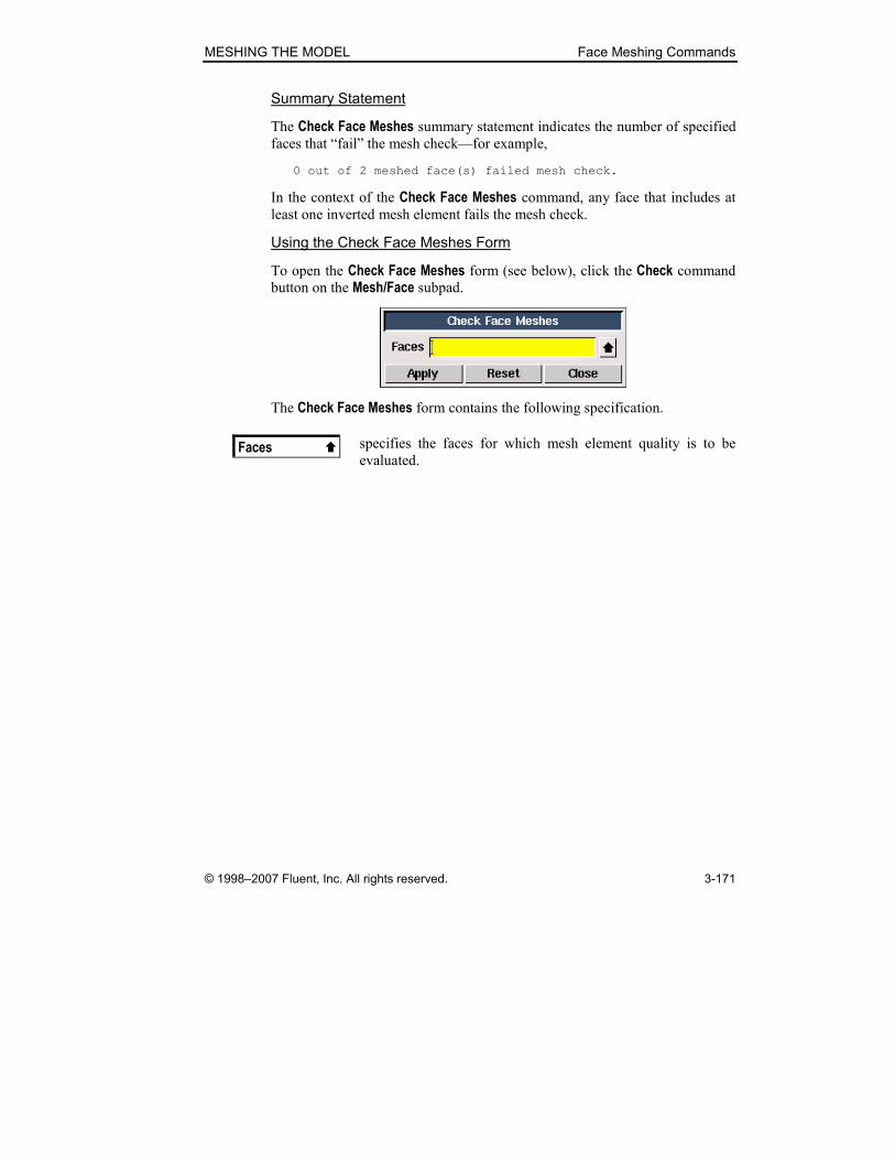
MESHING THE MODEL Face Meshing Commands
© 1998–2007 Fluent, Inc. All rights reserved. 3-171
Summary Statement
The Check Face Meshes summary statement indicates the number of specified
faces that “fail” the mesh check—for example,
0 out of 2 meshed face(s) failed mesh check.
In the context of the Check Face Meshes command, any face that includes at
least one inverted mesh element fails the mesh check.
Using the Check Face Meshes Form
To open the Check Face Meshes form (see below), click the Check command
button on the Mesh/Face subpad.
The Check Face Meshes form contains the following specification.
Faces � specifies the faces for which mesh element quality is to be
evaluated.

Face Meshing Commands MESHING THE MODEL
3-172 © 1998–2007 Fluent, Inc. All rights reserved.
3.3.9 Delete Face Meshes
The Delete Face Meshes operation (face delete onlymesh command)
removes the mesh from one or more meshed faces. When you remove a face
mesh, GAMBIT allows you to retain or remove all edge meshes associated
with the face.
Using the Delete Face Meshes Form
To open the Delete Face Meshes form (see below), click the Delete command
button on the Mesh/Face subpad.
The Delete Face Meshes form contains the following options and specifica-
tions.
Faces � specifies the face(s) for which the mesh is deleted.
All � Pick
• All specifies all faces in the model.
• Pick specifies faces selected by means of the Faces list box.
���� Remove unused lower mesh
removes all unused lower-topology meshes associated with the
specified face(s).
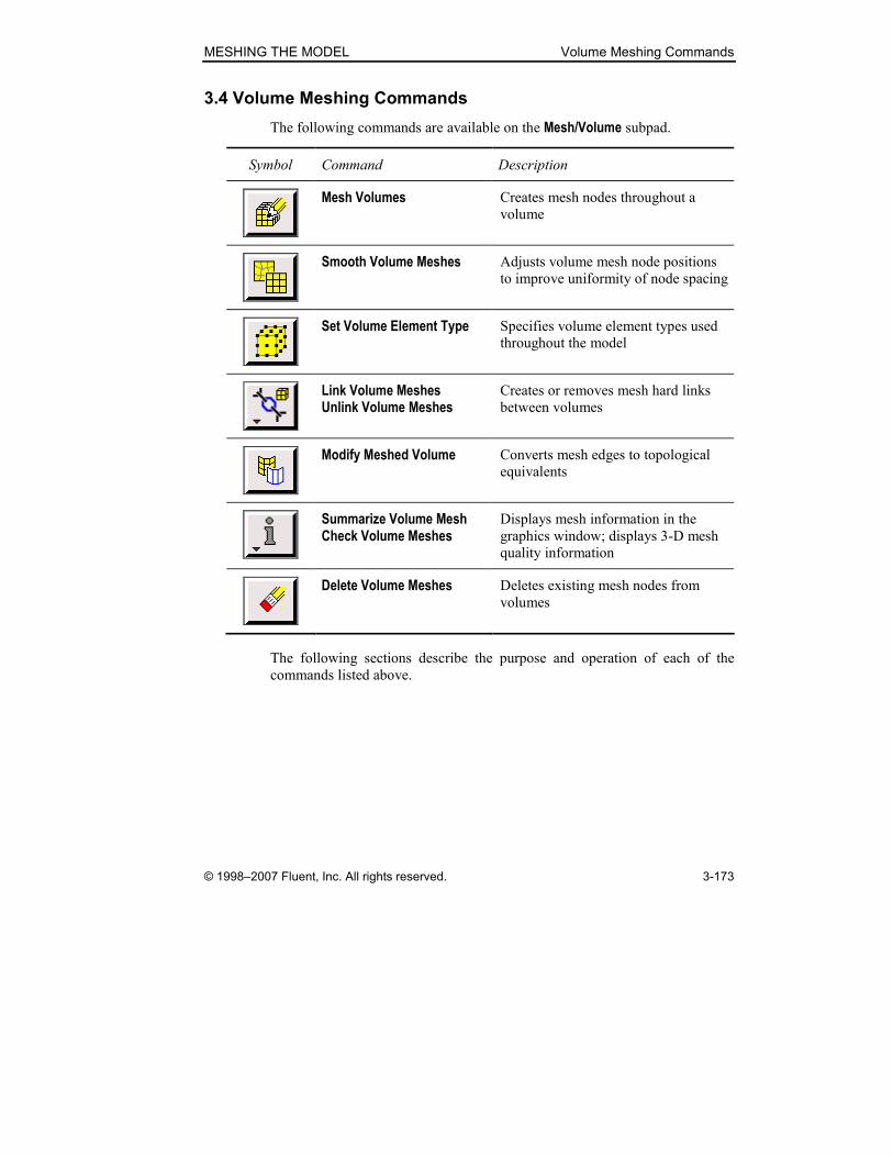
MESHING THE MODEL Volume Meshing Commands
© 1998–2007 Fluent, Inc. All rights reserved. 3-173
3.4 Volume Meshing Commands
The following commands are available on the Mesh/Volume subpad.
Symbol Command Description
Mesh Volumes Creates mesh nodes throughout a
volume
Smooth Volume Meshes Adjusts volume mesh node positions
to improve uniformity of node spacing
Set Volume Element Type Specifies volume element types used
throughout the model
Link Volume Meshes Unlink Volume Meshes
Creates or removes mesh hard links
between volumes
Modify Meshed Volume Converts mesh edges to topological
equivalents
Summarize Volume Mesh Check Volume Meshes
Displays mesh information in the
graphics window; displays 3-D mesh
quality information
Delete Volume Meshes Deletes existing mesh nodes from
volumes
The following sections describe the purpose and operation of each of the
commands listed above.
Volume Meshing Commands MESHING THE MODEL
3-174 © 1998–2007 Fluent, Inc. All rights reserved.
3.4.1 Mesh Volumes
The Mesh Volumes operation (volume mesh and volume modify com-
mands) creates a mesh for one or more volumes in the model. When you mesh
a volume, GAMBIT creates mesh nodes throughout the volume according to
the currently specified meshing parameters.
� NOTE: When meshing a volume, GAMBIT meshes any unmeshed faces on
the volume boundary before creating the volume mesh. If any newly created
face mesh includes elements the default quality metric of which exceeds the
current default upper limit, GAMBIT aborts the volume meshing operation
without creating the volume mesh.
The default quality metric and default upper limit are specified by means of
two MESH.EXAMINE default variables:
• ELEMENT_2D_QUALITY
• ELEMENT_QUALITY_LIMIT
For example, if you specify
• ELEMENT_2D_QUALITY = 2
• ELEMENT_QUALITY_LIMIT = 0.93
then GAMBIT will abort the volume meshing operation if any 2-D element on
the newly meshed faces possesses an Aspect Ratio quality metric value greater
than 0.93.
GAMBIT does not apply the criteria described above to any boundary faces
that are pre-meshed—that is, meshed prior to the volume meshing operation.
To mesh a volume, you must specify the following parameters:
• Volume(s) to be meshed
• Meshing scheme
• Mesh node spacing
• Meshing options
MESHING THE MODEL Volume Meshing Commands
© 1998–2007 Fluent, Inc. All rights reserved. 3-175
Specifying the Volume
GAMBIT allows you to specify any volume for a meshing operation; how-
ever, the shape and topological characteristics of the volume, as well as the
vertex types associated with its faces, determine the type(s) of mesh scheme(s)
that can be applied to the volume.
Specifying the Meshing Scheme
To specify the meshing scheme, you must specify the following parameters:
• Elements
• Type
• Smoother (Map meshes only)
The Elements parameter defines the shape(s) of the elements that are used to
mesh the volume. The Type parameter defines the meshing algorithm and,
therefore, the overall pattern of mesh elements in the volume. The Smoother specification determines the type of smoothing algorithm (if any) used to
smooth a mapped mesh during the meshing operation.
The following sections describe the parameters listed above and their effects
on the overall volume mesh.
Specifying Scheme Elements
GAMBIT allows you to specify any of the following volume meshing
Elements options. (NOTE: For descriptions of the basic shapes of each of the mesh elements listed below, see Section 3.4.3.)
Option Description
Hex Specifies that the mesh includes only hexahedral elements
Hex/Wedge Specifies that the mesh is composed primarily of hexahedral
elements but includes wedge elements where appropriate
Tet/Hybrid Specifies that the mesh is composed of tetrahedral,
hexahedral, pyramidal, and wedge elements where
appropriate
Each of the Elements options listed above is associated with a specific set of Type options (see below).
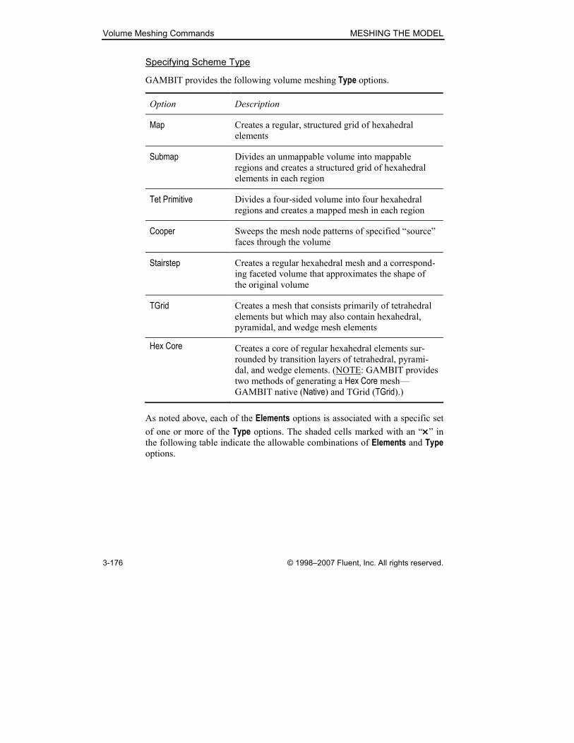
Volume Meshing Commands MESHING THE MODEL
3-176 © 1998–2007 Fluent, Inc. All rights reserved.
Specifying Scheme Type
GAMBIT provides the following volume meshing Type options.
Option Description
Map Creates a regular, structured grid of hexahedral
elements
Submap Divides an unmappable volume into mappable
regions and creates a structured grid of hexahedral
elements in each region
Tet Primitive Divides a four-sided volume into four hexahedral
regions and creates a mapped mesh in each region
Cooper Sweeps the mesh node patterns of specified “source”
faces through the volume
Stairstep Creates a regular hexahedral mesh and a correspond-
ing faceted volume that approximates the shape of
the original volume
TGrid Creates a mesh that consists primarily of tetrahedral
elements but which may also contain hexahedral,
pyramidal, and wedge mesh elements
Hex Core Creates a core of regular hexahedral elements sur-
rounded by transition layers of tetrahedral, pyrami-
dal, and wedge elements. (NOTE: GAMBIT provides
two methods of generating a Hex Core mesh—
GAMBIT native (Native) and TGrid (TGrid).)
As noted above, each of the Elements options is associated with a specific set
of one or more of the Type options. The shaded cells marked with an “××××” in the following table indicate the allowable combinations of Elements and Type options.
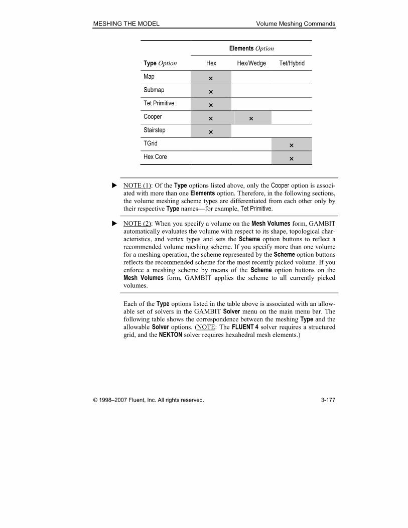
MESHING THE MODEL Volume Meshing Commands
© 1998–2007 Fluent, Inc. All rights reserved. 3-177
Elements Option
Type Option Hex Hex/Wedge Tet/Hybrid
Map ××××
Submap ××××
Tet Primitive ××××
Cooper ×××× ××××
Stairstep ××××
TGrid ××××
Hex Core ××××
� NOTE (1): Of the Type options listed above, only the Cooper option is associ-ated with more than one Elements option. Therefore, in the following sections, the volume meshing scheme types are differentiated from each other only by
their respective Type names—for example, Tet Primitive.
� NOTE (2): When you specify a volume on the Mesh Volumes form, GAMBIT
automatically evaluates the volume with respect to its shape, topological char-
acteristics, and vertex types and sets the Scheme option buttons to reflect a recommended volume meshing scheme. If you specify more than one volume
for a meshing operation, the scheme represented by the Scheme option buttons reflects the recommended scheme for the most recently picked volume. If you
enforce a meshing scheme by means of the Scheme option buttons on the Mesh Volumes form, GAMBIT applies the scheme to all currently picked
volumes.
Each of the Type options listed in the table above is associated with an allow-able set of solvers in the GAMBIT Solver menu on the main menu bar. The
following table shows the correspondence between the meshing Type and the allowable Solver options. (NOTE: The FLUENT 4 solver requires a structured grid, and the NEKTON solver requires hexahedral mesh elements.)

Volume Meshing Commands MESHING THE MODEL
3-178 © 1998–2007 Fluent, Inc. All rights reserved.
Type Option
Solver Option Map Submap Tet
Primitive Cooper Stairstep TGrid Hex
Core
FIDAP ×××× ×××× ×××× ×××× ×××× ×××× ××××
FLUENT/UNS ×××× ×××× ×××× ×××× ×××× ×××× ××××
FLUENT 5/6 ×××× ×××× ×××× ×××× ×××× ×××× ××××
FLUENT 4 ×××× ×××× ×××× ××××
NEKTON ×××× ×××× ×××× ×××× ××××
RAMPANT ×××× ×××× ×××× ×××× ×××× ×××× ××××
POLYFLOW ×××× ×××× ×××× ×××× ×××× ×××× ××××
Generic ×××× ×××× ×××× ×××× ×××× ×××× ××××
The correspondences shown in this table indicate which meshing schemes can
produce usable meshes for any given solver, but they do not guarantee that all
meshes created using a given meshing scheme will create usable meshes. For
example, the Stairstep and Hex Core meshing schemes can create meshes
usable by the FIDAP solver; however, they are also capable of creating meshes
that cannot be used by FIDAP—for example, those with hanging nodes.

MESHING THE MODEL Volume Meshing Commands
© 1998–2007 Fluent, Inc. All rights reserved. 3-179
Map Meshing Scheme
When you apply the Map meshing scheme to a volume, GAMBIT meshes the
volume using an array of hexahedral mesh elements, such as those shown in
Figure 3-77.
Figure 3-77: Map meshing scheme—partial array of hexahedral elements
Each mesh element includes at least eight nodes—located at the corners of the
element. If you specify an alternative volume element node pattern, GAMBIT
creates either 20 or 27 nodes per mesh element (see “Set Volume Element
Type,” below).
Specifying the Smoother Algorithm
If you mesh a volume using a Map meshing scheme, you can automatically
smooth the mesh during meshing by means of a Smoother algorithm. (NOTE:
You can manually smooth any existing volume mesh by means of the Smooth Volume Meshes command (see Section 3.4.2, below).)
GAMBIT provides two Smoother options for volumes:
• None—No smoother applied during meshing
• Hilg-Wht— Hilgenstock-White algorithm

Volume Meshing Commands MESHING THE MODEL
3-180 © 1998–2007 Fluent, Inc. All rights reserved.
If you specify the Hilg-Wht option, you must also specify a Source face. When
meshing the volume, GAMBIT applies the Hilgenstock-White smoothing
algorithm to minimize the effects of node bunching on volume boundary
edges that are connected to (but do not bound) the Source face. Such node bunching can cause element packing within the volume. The Hilg-Wht option is particularly useful whenever one of the boundary faces (the Source face) of the volume is curved.
General Applicability
The Map volume meshing scheme can only be applied to volumes that can be
meshed such that the mesh represents a logical cube. To represent a logical
cube, a volume mesh must satisfy the following general requirements.
1. There must exist exactly eight mesh nodes that are attached to only
three mesh element faces. (These eight mesh nodes comprise the cor-
ners of the logical cube.)
2. Each of the eight corner mesh nodes must be connected to three other
corner mesh nodes by means of a straight chain of mesh edges—that
is, a chain of mesh edges all of which belong to a single logical row of
mesh nodes.
According to the criteria described above, the most basic form of a mappable
volume is a rectangular brick, such as that shown in Figure 3-77, above. For
such a volume, the mesh nodes located at the corner vertices of the brick con-
stitute the corners of the mesh cube.
Although the strict definition of volume mappability is best expressed in terms
of the mesh itself, it is possible to state mappability requirements in terms of
the general geometrical configuration of a given volume. Specifically, volume
mappability criteria may be stated as follows:
To be mappable, a volume should contain six sides, each of which can
be rendered mappable by the correct specification of vertex types.
(For an exception to the criteria described above, see “Mapping Volumes with
Fewer Than Six Faces,” below.)
� NOTE: Any side of the volume may consist of more than one face.
As an example of the application of the general rule stated above, consider the
volumes shown in Figure 3-78.

MESHING THE MODEL Volume Meshing Commands
© 1998–2007 Fluent, Inc. All rights reserved. 3-181
(a) (b)
(c) (d)
Figure 3-78: Map volume meshing scheme—example volumes
Of the volumes shown in the figure, only the brick shown in Figure 3-78(a) is
mappable in its primitive form. However, it is possible to transform the other
volumes into mappable volumes by means of vertex-type assignments and vir-
tual geometry operations. The following sections describe the operations
required to render each volume mappable.
Transforming Volumes Into Mappable Forms
As noted above, the volumes shown in Figure 3-78(b), (c), and (d) are not
mappable in their primitive forms, but each can be transformed into a mappa-
ble volume by means of either vertex-type specifications or virtual geometry
operations. Specifically, the operations that are required to transform each
volume are as follows.
Figure 3-78 Shape Operation
(b) Pentagonal prism Vertex-type specification
(c) Cylinder Virtual edge-split
(d) Clipped cube Virtual face collapse

Volume Meshing Commands MESHING THE MODEL
3-182 © 1998–2007 Fluent, Inc. All rights reserved.
Pentagonal Prism—Specifying Vertex Types
To transform the pentagonal prism shown in Figure 3-78(b) into a mappable
volume, you must specify its vertex types such that the top and bottom faces
are mappable. To do so, you must specify one vertex on each of the top and
bottom faces as a Side vertex and all other vertices as End vertices (see Figure 3-79(a)).
(a) (b)
Side
Side
EndEnd
EndEnd
End
End
EndEnd
A
B
C
Figure 3-79: Mappable pentagonal prism volume
Figure 3-79(b) shows the Map volume mesh that results from the vertex speci-
fications shown in Figure 3-79(a). Note that faces A and B in the figure com-
prise one side of the logical mesh cube and that face C, by itself, constitutes
the opposing side.
When you assign vertex types to transform a prism into a mappable volume,
you must specify the vertex types such that the Side vertices on the top and bottom faces are connected to each other by means of a single vertical edge.
For example, if you assign vertex types according to the specifications shown
in Figure 3-80, GAMBIT cannot create a Map volume mesh in the prism,
because the configuration cannot be made to represent a logical mesh cube.
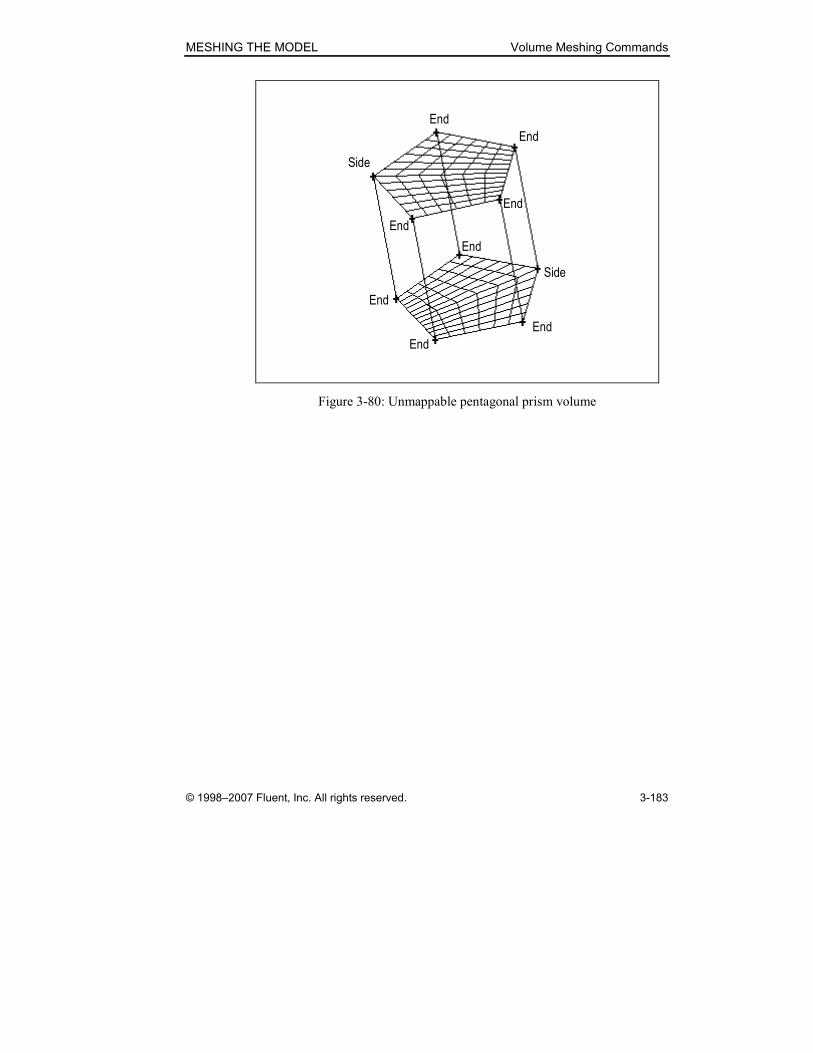
MESHING THE MODEL Volume Meshing Commands
© 1998–2007 Fluent, Inc. All rights reserved. 3-183
Side
End
End
End
End
End
Side
End
End
End
Figure 3-80: Unmappable pentagonal prism volume

Volume Meshing Commands MESHING THE MODEL
3-184 © 1998–2007 Fluent, Inc. All rights reserved.
Cylinder—Splitting Edges and Faces
The cylinder shown in Figure 3-78(c) is not mappable in its primitive form,
but it is possible to transform the cylinder into a mappable volume by means
of virtual edge-split and face-split operations. (For descriptions of the virtual
edge-split and face-split operations, see the appendix of this guide.)
If you split the edges that circumscribe the end caps and use the resulting
vertices to split the cylindrical face into four separate faces, the end faces
become mappable (see Figure 3-81(a)), and the cylinder becomes topologi-
cally equivalent to the brick shown in Figure 3-78(a). As a result, the cylinder
can be meshed according to the Map meshing scheme (see Figure 3-81(b)).
(b)(a)
End
End
End
End
End
End
End
End
Figure 3-81: Mappable cylinder
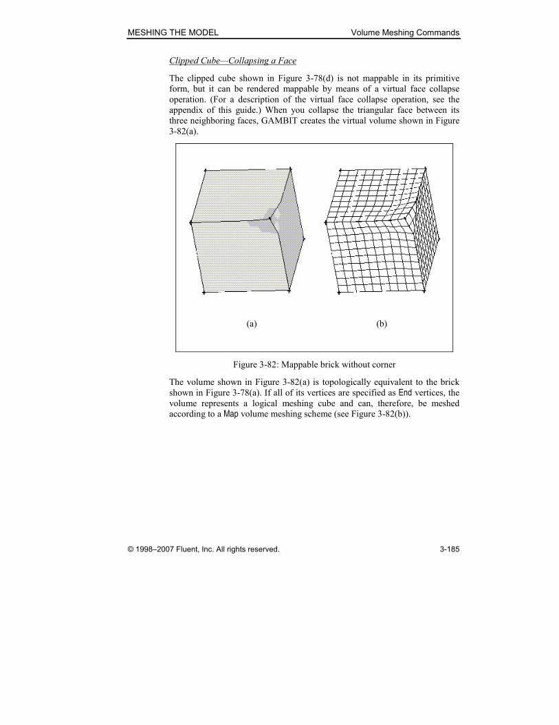
MESHING THE MODEL Volume Meshing Commands
© 1998–2007 Fluent, Inc. All rights reserved. 3-185
Clipped Cube—Collapsing a Face
The clipped cube shown in Figure 3-78(d) is not mappable in its primitive
form, but it can be rendered mappable by means of a virtual face collapse
operation. (For a description of the virtual face collapse operation, see the
appendix of this guide.) When you collapse the triangular face between its
three neighboring faces, GAMBIT creates the virtual volume shown in Figure
3-82(a).
(b)(a)
Figure 3-82: Mappable brick without corner
The volume shown in Figure 3-82(a) is topologically equivalent to the brick
shown in Figure 3-78(a). If all of its vertices are specified as End vertices, the volume represents a logical meshing cube and can, therefore, be meshed
according to a Map volume meshing scheme (see Figure 3-82(b)).
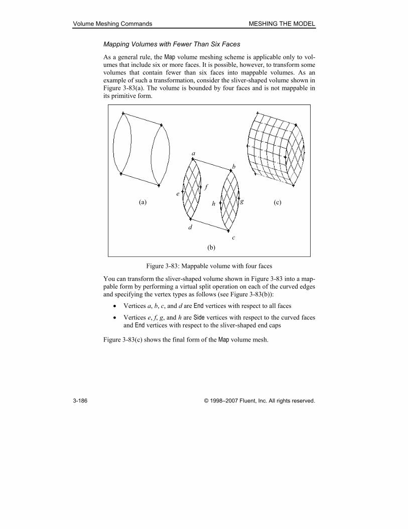
Volume Meshing Commands MESHING THE MODEL
3-186 © 1998–2007 Fluent, Inc. All rights reserved.
Mapping Volumes with Fewer Than Six Faces
As a general rule, the Map volume meshing scheme is applicable only to vol-
umes that include six or more faces. It is possible, however, to transform some
volumes that contain fewer than six faces into mappable volumes. As an
example of such a transformation, consider the sliver-shaped volume shown in
Figure 3-83(a). The volume is bounded by four faces and is not mappable in
its primitive form.
(a)
(b)
(c)
a
b
c
d
fe
gh
Figure 3-83: Mappable volume with four faces
You can transform the sliver-shaped volume shown in Figure 3-83 into a map-
pable form by performing a virtual split operation on each of the curved edges
and specifying the vertex types as follows (see Figure 3-83(b)):
• Vertices a, b, c, and d are End vertices with respect to all faces
• Vertices e, f, g, and h are Side vertices with respect to the curved faces and End vertices with respect to the sliver-shaped end caps
Figure 3-83(c) shows the final form of the Map volume mesh.
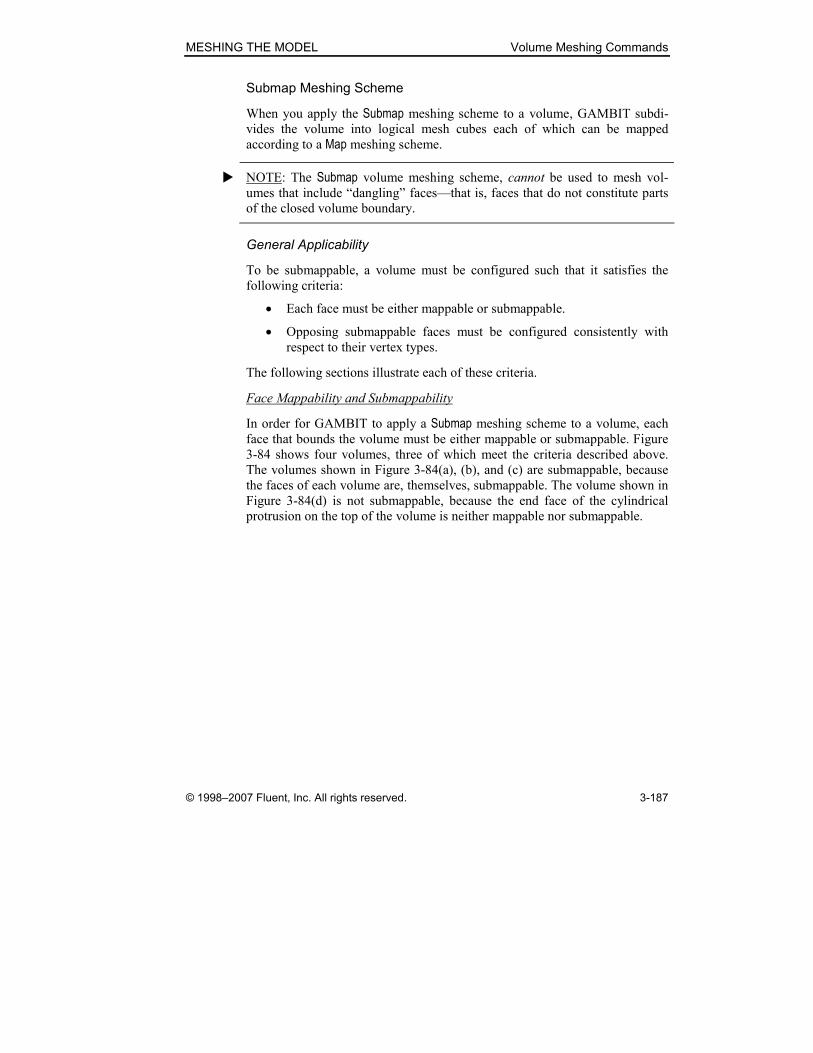
MESHING THE MODEL Volume Meshing Commands
© 1998–2007 Fluent, Inc. All rights reserved. 3-187
Submap Meshing Scheme
When you apply the Submap meshing scheme to a volume, GAMBIT subdi-
vides the volume into logical mesh cubes each of which can be mapped
according to a Map meshing scheme.
� NOTE: The Submap volume meshing scheme, cannot be used to mesh vol-
umes that include “dangling” faces—that is, faces that do not constitute parts
of the closed volume boundary.
General Applicability
To be submappable, a volume must be configured such that it satisfies the
following criteria:
• Each face must be either mappable or submappable.
• Opposing submappable faces must be configured consistently with
respect to their vertex types.
The following sections illustrate each of these criteria.
Face Mappability and Submappability
In order for GAMBIT to apply a Submap meshing scheme to a volume, each
face that bounds the volume must be either mappable or submappable. Figure
3-84 shows four volumes, three of which meet the criteria described above.
The volumes shown in Figure 3-84(a), (b), and (c) are submappable, because
the faces of each volume are, themselves, submappable. The volume shown in
Figure 3-84(d) is not submappable, because the end face of the cylindrical
protrusion on the top of the volume is neither mappable nor submappable.
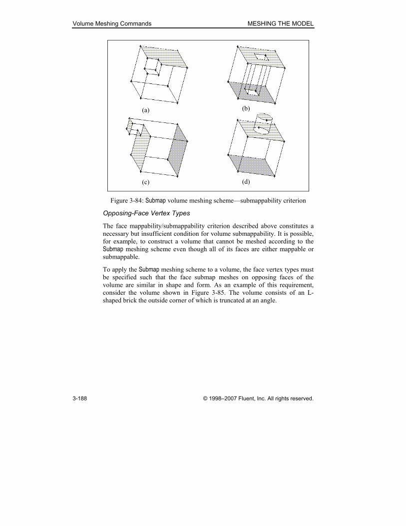
Volume Meshing Commands MESHING THE MODEL
3-188 © 1998–2007 Fluent, Inc. All rights reserved.
(a) (b)
(c) (d)
Figure 3-84: Submap volume meshing scheme—submappability criterion
Opposing-Face Vertex Types
The face mappability/submappability criterion described above constitutes a
necessary but insufficient condition for volume submappability. It is possible,
for example, to construct a volume that cannot be meshed according to the
Submap meshing scheme even though all of its faces are either mappable or
submappable.
To apply the Submap meshing scheme to a volume, the face vertex types must
be specified such that the face submap meshes on opposing faces of the
volume are similar in shape and form. As an example of this requirement,
consider the volume shown in Figure 3-85. The volume consists of an L-
shaped brick the outside corner of which is truncated at an angle.
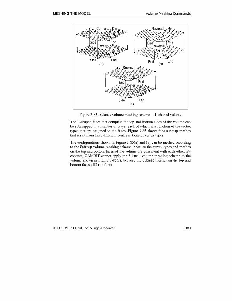
MESHING THE MODEL Volume Meshing Commands
© 1998–2007 Fluent, Inc. All rights reserved. 3-189
(a)
(c)
End
Corner
Side
End
Corner
Side
End
Reversal
End
End
Reversal
End
End
Corner
Side
End
Reversal
End
(b)
Figure 3-85: Submap volume meshing scheme— L-shaped volume
The L-shaped faces that comprise the top and bottom sides of the volume can
be submapped in a number of ways, each of which is a function of the vertex
types that are assigned to the faces. Figure 3-85 shows face submap meshes
that result from three different configurations of vertex types.
The configurations shown in Figure 3-85(a) and (b) can be meshed according
to the Submap volume meshing scheme, because the vertex types and meshes
on the top and bottom faces of the volume are consistent with each other. By
contrast, GAMBIT cannot apply the Submap volume meshing scheme to the
volume shown in Figure 3-85(c), because the Submap meshes on the top and
bottom faces differ in form.

Volume Meshing Commands MESHING THE MODEL
3-190 © 1998–2007 Fluent, Inc. All rights reserved.
Tet Primitive Meshing Scheme
The Tet Primitive volume meshing scheme applies only to volumes that consti-
tute logical tetrahedra. To constitute a logical tetrahedron, a volume must
include only four sides, each of which constitutes a logical triangle. When you
apply the Tet Primitive meshing scheme, GAMBIT creates Tri Primitive meshes
on each of the faces of the tetrahedron, then subdivides the volume into four
hexahedral quadrants and creates a Map-type volume mesh in each quadrant.
As an example of the Tet Primitive meshing scheme, consider the tetrahedral
volume shown in Figure 3-86(a). If you apply the Tet Primitive meshing scheme
to the volume, GAMBIT creates Tri Primitive meshes on each face (see Figure
3-86(b)), then subdivides the volume into four quadrants and meshes each
quadrant with hexahedral mesh elements. Figure 3-86(c) shows a cutaway
view of the final mesh.
(a)
(c)
(b)
Figure 3-86: Tet Primitive volume meshing scheme
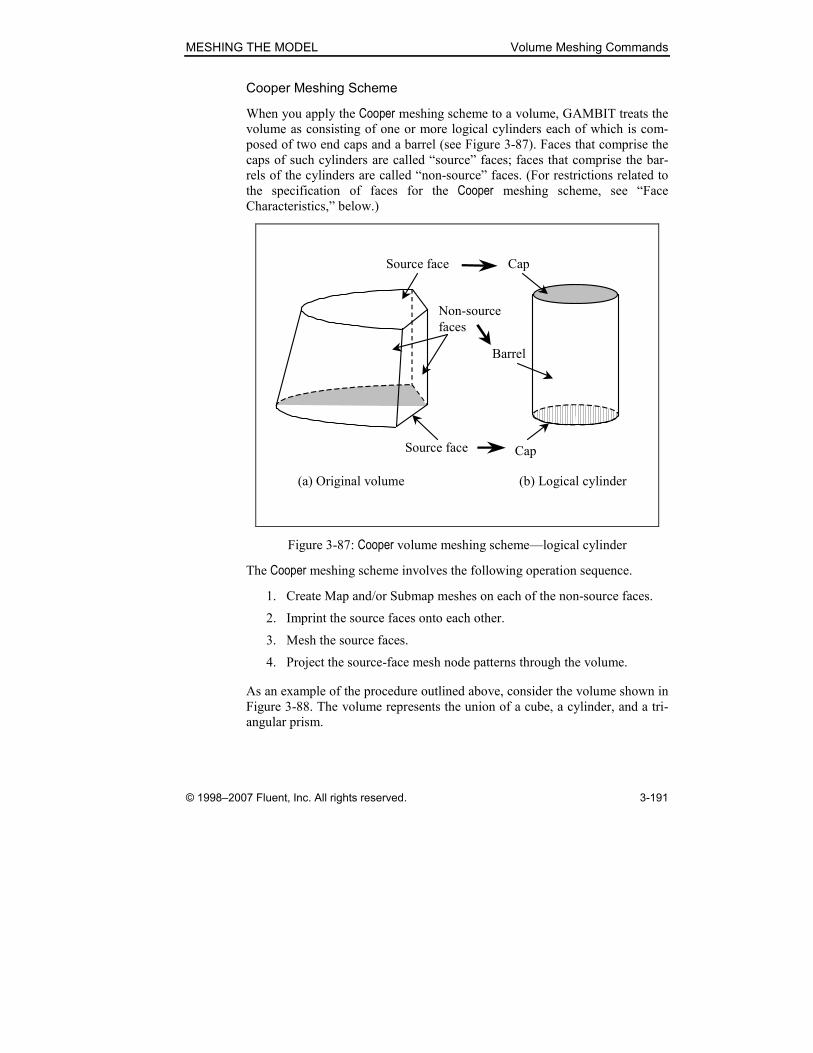
MESHING THE MODEL Volume Meshing Commands
© 1998–2007 Fluent, Inc. All rights reserved. 3-191
Cooper Meshing Scheme
When you apply the Cooper meshing scheme to a volume, GAMBIT treats the
volume as consisting of one or more logical cylinders each of which is com-
posed of two end caps and a barrel (see Figure 3-87). Faces that comprise the
caps of such cylinders are called “source” faces; faces that comprise the bar-
rels of the cylinders are called “non-source” faces. (For restrictions related to
the specification of faces for the Cooper meshing scheme, see “Face
Characteristics,” below.)
Non-source
faces
Source face
Source face
(a) Original volume (b) Logical cylinder
Cap
Barrel
Cap
Figure 3-87: Cooper volume meshing scheme—logical cylinder
The Cooper meshing scheme involves the following operation sequence.
1. Create Map and/or Submap meshes on each of the non-source faces.
2. Imprint the source faces onto each other.
3. Mesh the source faces.
4. Project the source-face mesh node patterns through the volume.
As an example of the procedure outlined above, consider the volume shown in
Figure 3-88. The volume represents the union of a cube, a cylinder, and a tri-
angular prism.

Volume Meshing Commands MESHING THE MODEL
3-192 © 1998–2007 Fluent, Inc. All rights reserved.
Figure 3-88: Cooper volume meshing scheme—example volume
If you apply the Cooper meshing scheme to the volume shown in Figure 3-88,
GAMBIT performs the following operations (see Figure 3-89).
1. Mesh the non-source faces (see Figure 3-89(a)).
2. Imprint the source faces onto each other (see Figure 3-89(b)). (NOTE:
Regions A’ and B’ represent the imprinting of faces A and B, respec-
tively.)
3. Mesh each of the source faces (see Figure 3-89(c)).
4. Project the source-face mesh node patterns through the volume (see
Figure 3-89(d)).
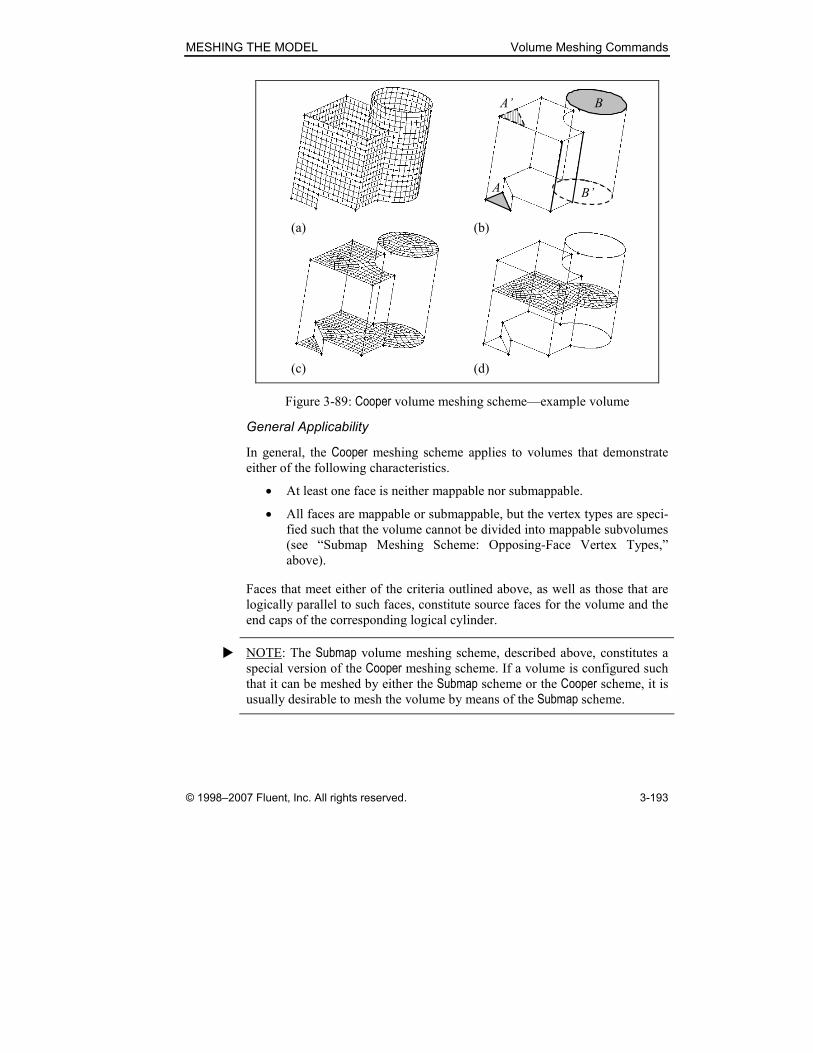
MESHING THE MODEL Volume Meshing Commands
© 1998–2007 Fluent, Inc. All rights reserved. 3-193
B’
BA’
A
(a) (b)
(c) (d)
Figure 3-89: Cooper volume meshing scheme—example volume
General Applicability
In general, the Cooper meshing scheme applies to volumes that demonstrate
either of the following characteristics.
• At least one face is neither mappable nor submappable.
• All faces are mappable or submappable, but the vertex types are speci-
fied such that the volume cannot be divided into mappable subvolumes
(see “Submap Meshing Scheme: Opposing-Face Vertex Types,”
above).
Faces that meet either of the criteria outlined above, as well as those that are
logically parallel to such faces, constitute source faces for the volume and the
end caps of the corresponding logical cylinder.
� NOTE: The Submap volume meshing scheme, described above, constitutes a
special version of the Cooper meshing scheme. If a volume is configured such
that it can be meshed by either the Submap scheme or the Cooper scheme, it is
usually desirable to mesh the volume by means of the Submap scheme.
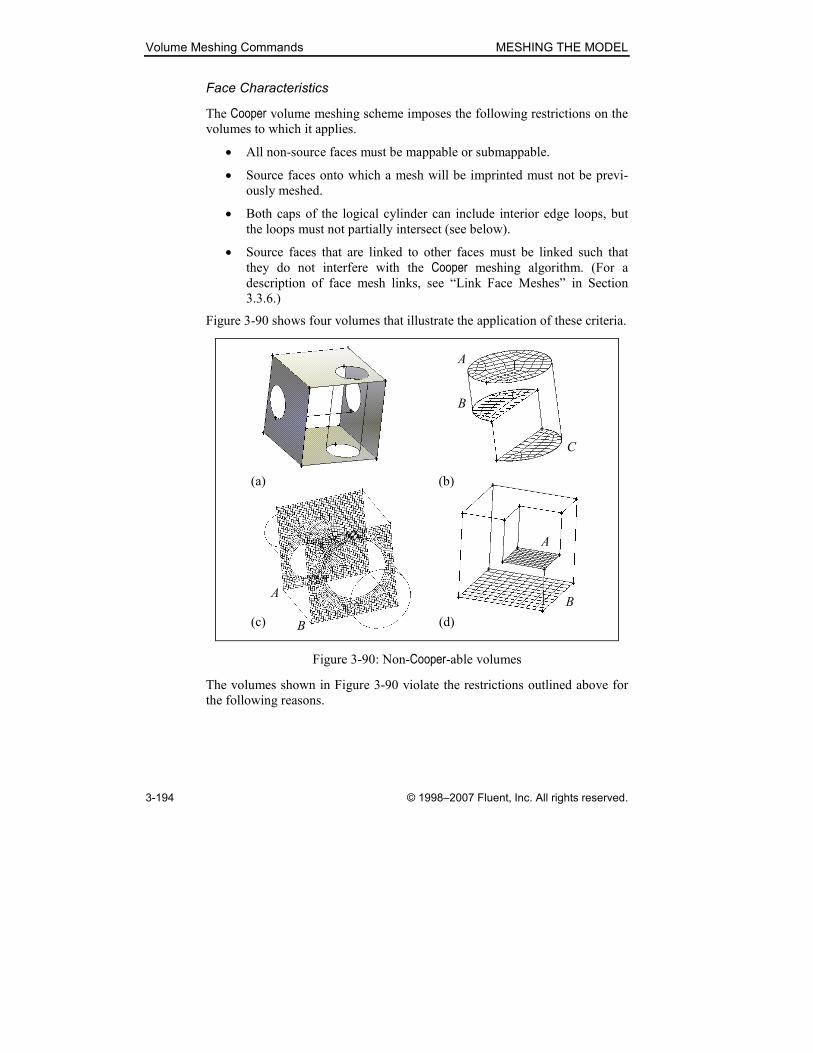
Volume Meshing Commands MESHING THE MODEL
3-194 © 1998–2007 Fluent, Inc. All rights reserved.
Face Characteristics
The Cooper volume meshing scheme imposes the following restrictions on the
volumes to which it applies.
• All non-source faces must be mappable or submappable.
• Source faces onto which a mesh will be imprinted must not be previ-
ously meshed.
• Both caps of the logical cylinder can include interior edge loops, but
the loops must not partially intersect (see below).
• Source faces that are linked to other faces must be linked such that
they do not interfere with the Cooper meshing algorithm. (For a
description of face mesh links, see “Link Face Meshes” in Section
3.3.6.)
Figure 3-90 shows four volumes that illustrate the application of these criteria.
(a) (b)
A
C
B
A
B
(c) (d)
A
B
Figure 3-90: Non-Cooper-able volumes
The volumes shown in Figure 3-90 violate the restrictions outlined above for
the following reasons.

MESHING THE MODEL Volume Meshing Commands
© 1998–2007 Fluent, Inc. All rights reserved. 3-195
Volume Criterion Reason
Figure 3-90(a) (1) It is impossible to construct a logical cyl-
inder the barrel of which is mappable.
Figure 3-90(b) (2) GAMBIT cannot imprint the mesh from
faces B and C onto face A, because face A
possesses an existing mesh.
Figure 3-90(c) (3) Opposing faces (A and B) that constitute
the caps of the logical cylinder contain
interior edge loops the projections of
which overlap.
Figure 3-90(d) (4) Face A is linked to face B, therefore
GAMBIT cannot imprint the face A mesh
onto face B, because the imprint would
violate the operation of the mesh link.
As noted above, cap faces on the logical cylinder of the Cooper-able volume
can include interior edge loops, but the projections of the loops must not par-
tially intersect each other, as they do in Figure 3-90(c). Figure 3-91 shows two
allowable cases involving interior edge loops on the caps of the logical
cylinder. Figure 3-91(a) is Cooper-able because the projections of the interior edge loops do not intersect each other at all. Figure 3-91(b) is Cooper-able because the interior edge loops fully intersect. (NOTE: If such fully intersect-
ing edge loops are premeshed, the mesh specifications on both loops must be
identical to each other.)
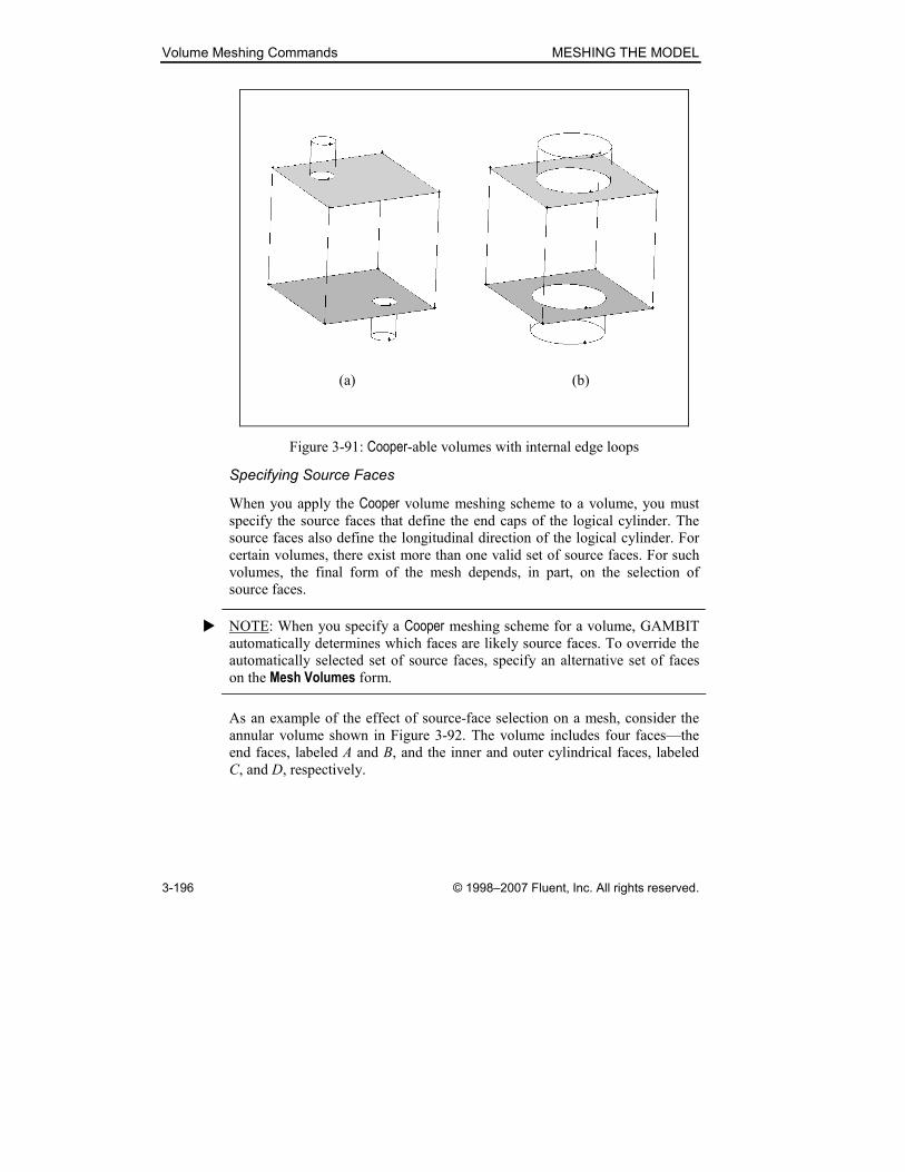
Volume Meshing Commands MESHING THE MODEL
3-196 © 1998–2007 Fluent, Inc. All rights reserved.
(a) (b)
Figure 3-91: Cooper-able volumes with internal edge loops
Specifying Source Faces
When you apply the Cooper volume meshing scheme to a volume, you must
specify the source faces that define the end caps of the logical cylinder. The
source faces also define the longitudinal direction of the logical cylinder. For
certain volumes, there exist more than one valid set of source faces. For such
volumes, the final form of the mesh depends, in part, on the selection of
source faces.
� NOTE: When you specify a Cooper meshing scheme for a volume, GAMBIT
automatically determines which faces are likely source faces. To override the
automatically selected set of source faces, specify an alternative set of faces
on the Mesh Volumes form.
As an example of the effect of source-face selection on a mesh, consider the
annular volume shown in Figure 3-92. The volume includes four faces—the
end faces, labeled A and B, and the inner and outer cylindrical faces, labeled
C, and D, respectively.
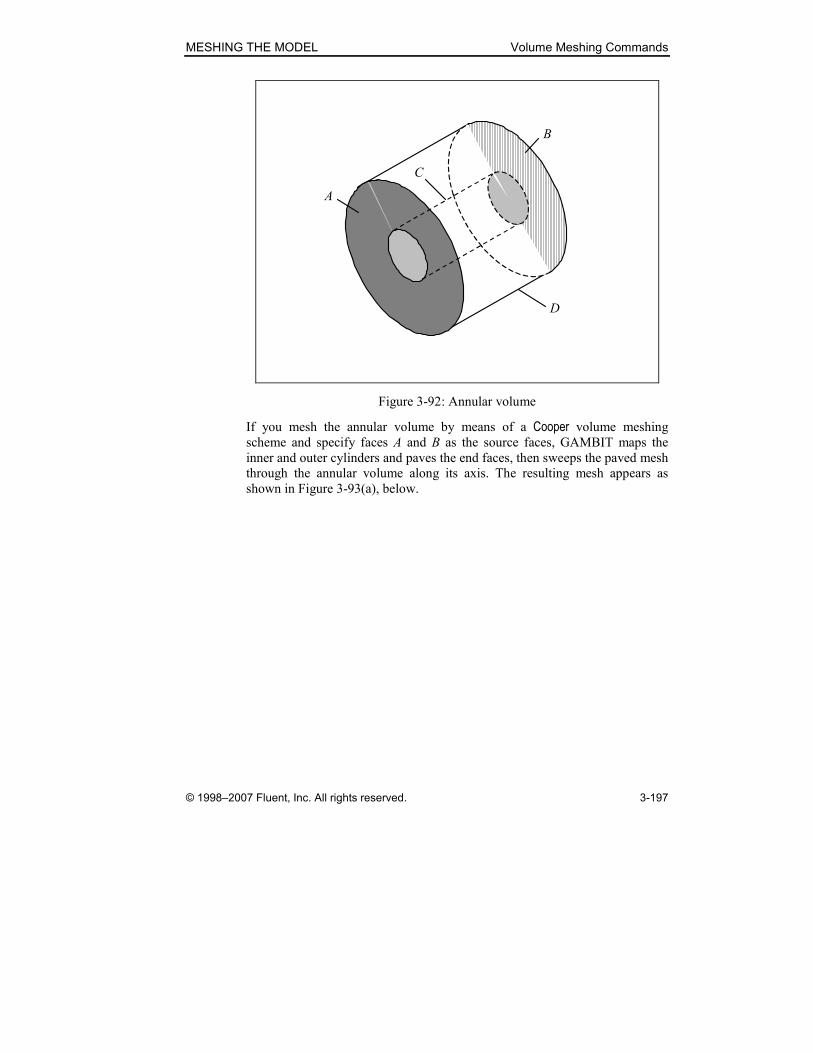
MESHING THE MODEL Volume Meshing Commands
© 1998–2007 Fluent, Inc. All rights reserved. 3-197
A
B
C
D
Figure 3-92: Annular volume
If you mesh the annular volume by means of a Cooper volume meshing
scheme and specify faces A and B as the source faces, GAMBIT maps the
inner and outer cylinders and paves the end faces, then sweeps the paved mesh
through the annular volume along its axis. The resulting mesh appears as
shown in Figure 3-93(a), below.
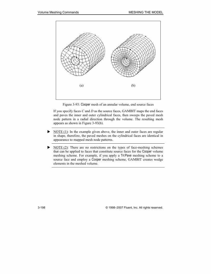
Volume Meshing Commands MESHING THE MODEL
3-198 © 1998–2007 Fluent, Inc. All rights reserved.
(a) (b)
Figure 3-93: Cooper mesh of an annular volume, end source faces
If you specify faces C and D as the source faces, GAMBIT maps the end faces
and paves the inner and outer cylindrical faces, then sweeps the paved mesh
node pattern in a radial direction through the volume. The resulting mesh
appears as shown in Figure 3-93(b).
� NOTE (1): In the example given above, the inner and outer faces are regular
in shape, therefore, the paved meshes on the cylindrical faces are identical in
appearance to mapped mesh node patterns.
� NOTE (2): There are no restrictions on the types of face-meshing schemes
that can be applied to faces that constitute source faces for the Cooper volume
meshing scheme. For example, if you apply a Tri:Pave meshing scheme to a
source face and employ a Cooper meshing scheme, GAMBIT creates wedge
elements in the meshed volume.
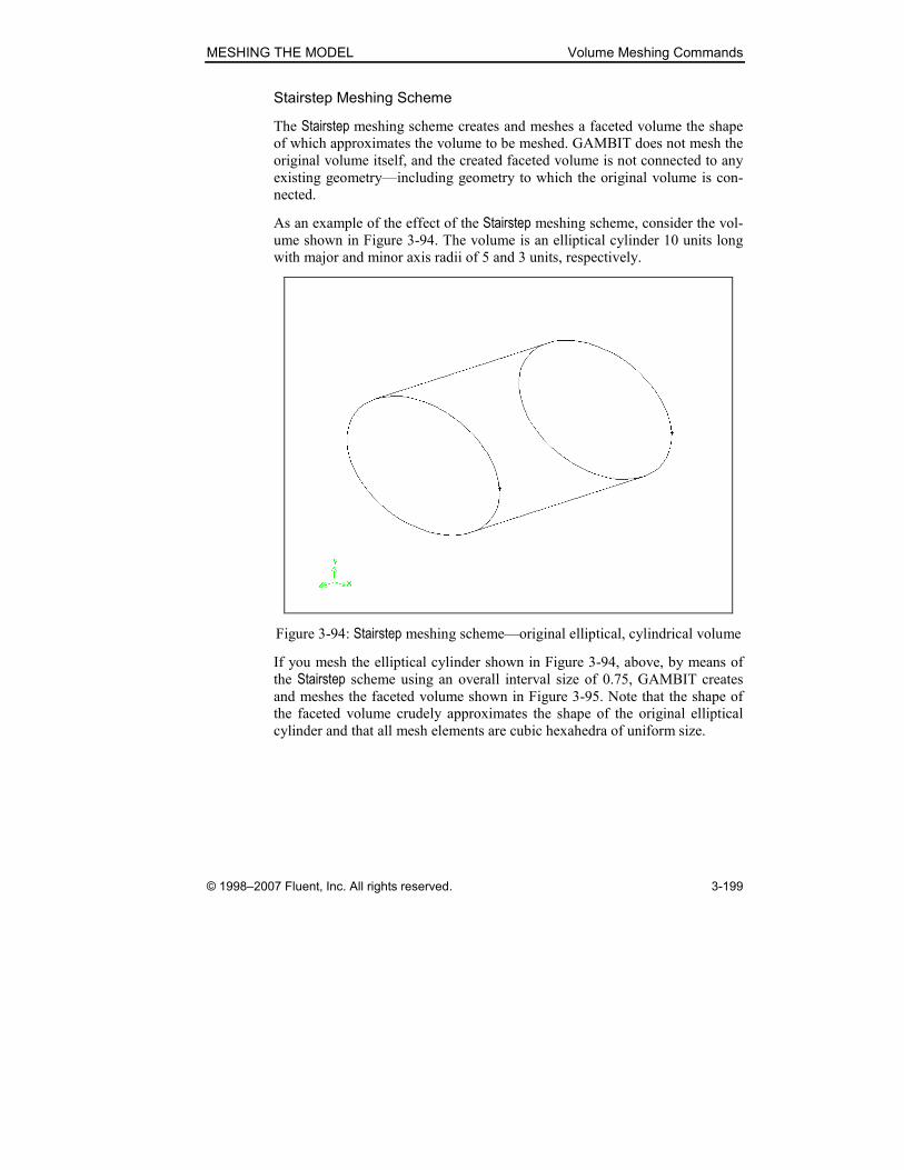
MESHING THE MODEL Volume Meshing Commands
© 1998–2007 Fluent, Inc. All rights reserved. 3-199
Stairstep Meshing Scheme
The Stairstep meshing scheme creates and meshes a faceted volume the shape
of which approximates the volume to be meshed. GAMBIT does not mesh the
original volume itself, and the created faceted volume is not connected to any
existing geometry—including geometry to which the original volume is con-
nected.
As an example of the effect of the Stairstep meshing scheme, consider the vol-
ume shown in Figure 3-94. The volume is an elliptical cylinder 10 units long
with major and minor axis radii of 5 and 3 units, respectively.
Figure 3-94: Stairstep meshing scheme—original elliptical, cylindrical volume
If you mesh the elliptical cylinder shown in Figure 3-94, above, by means of
the Stairstep scheme using an overall interval size of 0.75, GAMBIT creates
and meshes the faceted volume shown in Figure 3-95. Note that the shape of
the faceted volume crudely approximates the shape of the original elliptical
cylinder and that all mesh elements are cubic hexahedra of uniform size.
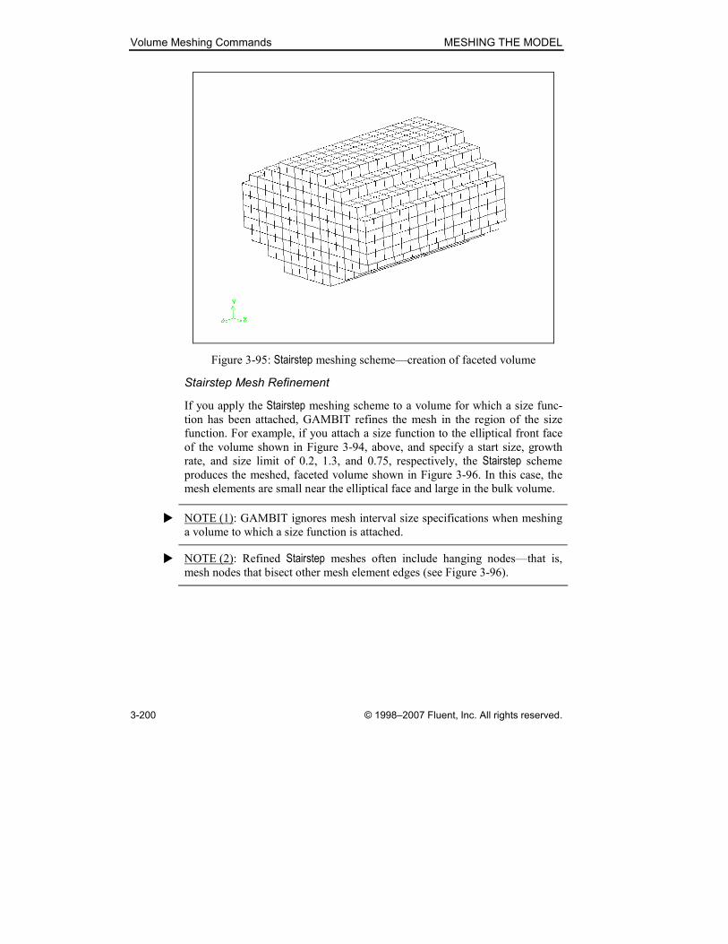
Volume Meshing Commands MESHING THE MODEL
3-200 © 1998–2007 Fluent, Inc. All rights reserved.
Figure 3-95: Stairstep meshing scheme—creation of faceted volume
Stairstep Mesh Refinement
If you apply the Stairstep meshing scheme to a volume for which a size func-
tion has been attached, GAMBIT refines the mesh in the region of the size
function. For example, if you attach a size function to the elliptical front face
of the volume shown in Figure 3-94, above, and specify a start size, growth
rate, and size limit of 0.2, 1.3, and 0.75, respectively, the Stairstep scheme
produces the meshed, faceted volume shown in Figure 3-96. In this case, the
mesh elements are small near the elliptical face and large in the bulk volume.
� NOTE (1): GAMBIT ignores mesh interval size specifications when meshing
a volume to which a size function is attached.
� NOTE (2): Refined Stairstep meshes often include hanging nodes—that is,
mesh nodes that bisect other mesh element edges (see Figure 3-96).

MESHING THE MODEL Volume Meshing Commands
© 1998–2007 Fluent, Inc. All rights reserved. 3-201
Hanging node
Figure 3-96: Stairstep meshing scheme—faceted volume with transition region
GAMBIT provides two options for refining the mesh in the Stairstep scheme.
One option allows the existence of hanging nodes such as those shown in
Figure 3-96. The other option disallows the existence of hanging nodes by
propagating the refined mesh throughout the entire volume. You can select the
Stairstep mesh refinement option by means of a GAMBIT default variable
named STAIRSTEP_MESH_TYPE. To modify the variable:
1. Open the Edit Defaults form.
2. Access the MESH default definition subform.
3. Choose the CARTESIAN option.
4. Select and modify the STAIRSTEP_MESH_TYPE default variable.
The value of the STAIRSTEP_MESH_TYPE default variable affects Stairstep mesh refinement in the following manner.
Value Description
0 Allows hanging nodes in the region of mesh refinement
1 Disallows hanging nodes by propagating the refined mesh
throughout the volume
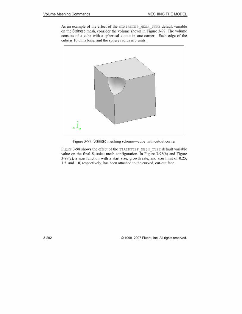
Volume Meshing Commands MESHING THE MODEL
3-202 © 1998–2007 Fluent, Inc. All rights reserved.
As an example of the effect of the STAIRSTEP_MESH_TYPE default variable
on the Stairstep mesh, consider the volume shown in Figure 3-97. The volume
consists of a cube with a spherical cutout in one corner. Each edge of the
cube is 10 units long, and the sphere radius is 3 units.
Figure 3-97: Stairstep meshing scheme—cube with cutout corner
Figure 3-98 shows the effect of the STAIRSTEP_MESH_TYPE default variable
value on the final Stairstep mesh configuration. In Figure 3-98(b) and Figure
3-98(c), a size function with a start size, growth rate, and size limit of 0.25,
1.5, and 1.0, respectively, has been attached to the curved, cut-out face.
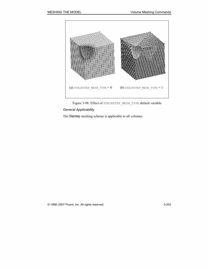
MESHING THE MODEL Volume Meshing Commands
© 1998–2007 Fluent, Inc. All rights reserved. 3-203
(a) STAIRSTEP_MESH_TYPE = 0 (b) STAIRSTEP_MESH_TYPE = 1
Figure 3-98: Effect of STAIRSTEP_MESH_TYPE default variable
General Applicability
The Stairstep meshing scheme is applicable to all volumes.
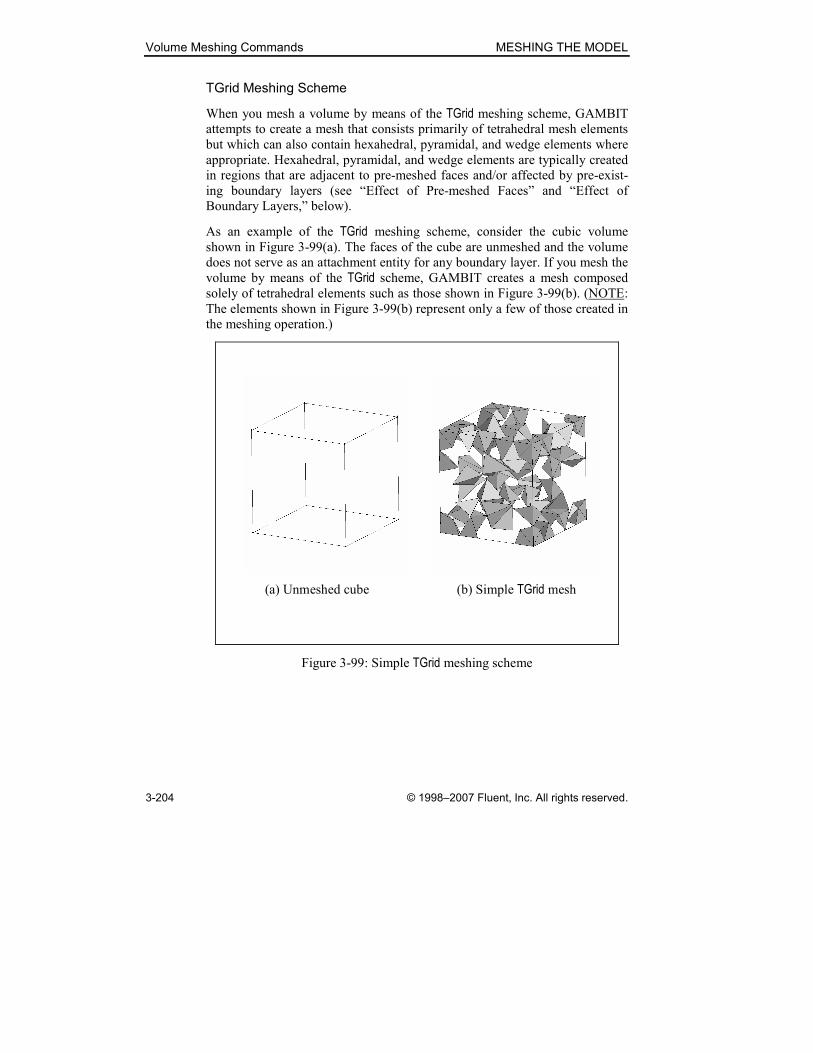
Volume Meshing Commands MESHING THE MODEL
3-204 © 1998–2007 Fluent, Inc. All rights reserved.
TGrid Meshing Scheme
When you mesh a volume by means of the TGrid meshing scheme, GAMBIT
attempts to create a mesh that consists primarily of tetrahedral mesh elements
but which can also contain hexahedral, pyramidal, and wedge elements where
appropriate. Hexahedral, pyramidal, and wedge elements are typically created
in regions that are adjacent to pre-meshed faces and/or affected by pre-exist-
ing boundary layers (see “Effect of Pre-meshed Faces” and “Effect of
Boundary Layers,” below).
As an example of the TGrid meshing scheme, consider the cubic volume
shown in Figure 3-99(a). The faces of the cube are unmeshed and the volume
does not serve as an attachment entity for any boundary layer. If you mesh the
volume by means of the TGrid scheme, GAMBIT creates a mesh composed
solely of tetrahedral elements such as those shown in Figure 3-99(b). (NOTE:
The elements shown in Figure 3-99(b) represent only a few of those created in
the meshing operation.)
(a) Unmeshed cube (b) Simple TGrid mesh
Figure 3-99: Simple TGrid meshing scheme

MESHING THE MODEL Volume Meshing Commands
© 1998–2007 Fluent, Inc. All rights reserved. 3-205
Effect of Pre-meshed Faces
If any of the volume boundary faces are pre-meshed using quadrilateral mesh
elements prior to volume meshing, the TGrid scheme (by default) creates a
layer of pyramidal mesh elements adjacent to the pre-meshed face. For
example, if you pre-mesh the bottom face of a cube using quadrilateral ele-
ments, as shown in Figure 3-100(a), the TGrid scheme creates a layer of
pyramidal elements adjacent to the pre-meshed face (see Figure 3-100(b)).
The TGrid scheme produces tetrahedral elements throughout the rest of the
cube.
(a) Quad face mesh (b) Pyramidal mesh elements
Figure 3-100: Effect of pre-meshed face on TGrid scheme
� NOTE (1): You can alter the default TGrid meshing behavior illustrated in
Figure 3-100, above, by means of the MESH.TETMESH.QUAD_SURFACE_
SPLIT default variable (see “Effect of QUAD_SURFACE_SPLIT Default
Variable,” below).
� NOTE (2): In general, it is advisable to avoid creating quadrilateral face mesh
elements with aspect ratios greater than five (5) on the boundaries of any vol-
ume to be meshed by means of the TGrid meshing scheme. Face mesh ele-
ments with high aspect ratios produce highly skewed transition pyramidal
elements, and the subsequent TGrid scheme may fail or produce low-quality
elements.
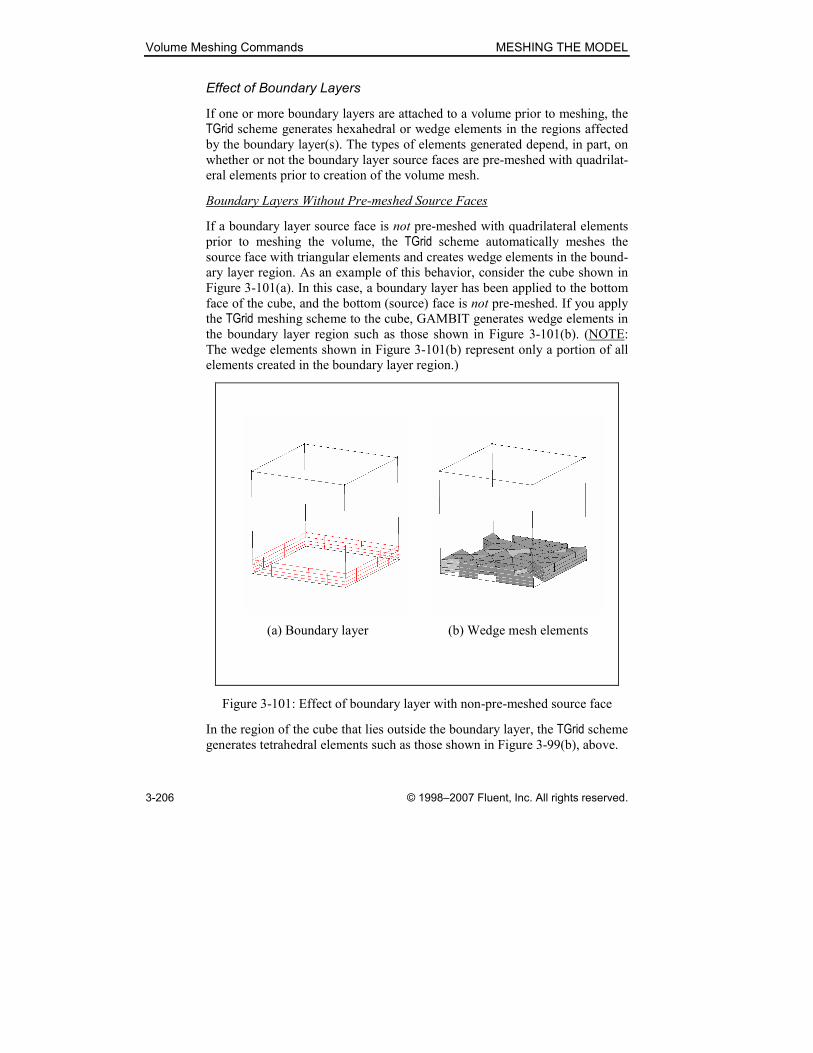
Volume Meshing Commands MESHING THE MODEL
3-206 © 1998–2007 Fluent, Inc. All rights reserved.
Effect of Boundary Layers
If one or more boundary layers are attached to a volume prior to meshing, the
TGrid scheme generates hexahedral or wedge elements in the regions affected
by the boundary layer(s). The types of elements generated depend, in part, on
whether or not the boundary layer source faces are pre-meshed with quadrilat-
eral elements prior to creation of the volume mesh.
Boundary Layers Without Pre-meshed Source Faces
If a boundary layer source face is not pre-meshed with quadrilateral elements
prior to meshing the volume, the TGrid scheme automatically meshes the
source face with triangular elements and creates wedge elements in the bound-
ary layer region. As an example of this behavior, consider the cube shown in
Figure 3-101(a). In this case, a boundary layer has been applied to the bottom
face of the cube, and the bottom (source) face is not pre-meshed. If you apply
the TGrid meshing scheme to the cube, GAMBIT generates wedge elements in
the boundary layer region such as those shown in Figure 3-101(b). (NOTE:
The wedge elements shown in Figure 3-101(b) represent only a portion of all
elements created in the boundary layer region.)
(a) Boundary layer (b) Wedge mesh elements
Figure 3-101: Effect of boundary layer with non-pre-meshed source face
In the region of the cube that lies outside the boundary layer, the TGrid scheme
generates tetrahedral elements such as those shown in Figure 3-99(b), above.

MESHING THE MODEL Volume Meshing Commands
© 1998–2007 Fluent, Inc. All rights reserved. 3-207
Boundary Layers with Pre-meshed Source Faces
If a boundary layer source face is pre-meshed with quadrilateral elements
prior to meshing the volume, the TGrid scheme retains the quadrilateral face
elements and creates hexahedral elements in the boundary layer region. As an
example of this behavior, consider the cube shown in Figure 3-102(a). In this
case, a boundary layer has been applied to the bottom face of the cube, and the
bottom (source) face is pre-meshed with quadrilateral elements. If you apply
the TGrid meshing scheme to the cube, GAMBIT generates hexahedral ele-
ments in the boundary layer region (see Figure 3-102(b)).
(a) Boundary layer with
pre-meshed face
(b) Hexahedral mesh elements
Figure 3-102: Effect of boundary layer with pre-meshed source face
In addition to creating hexahedral elements in the boundary layer region for
this case, the TGrid scheme generates a layer of pyramidal elements on the
boundary layer cap (see Figure 3-103(a)) and fills the rest of the volume with
tetrahedral elements, some of which are shown in Figure 3-103(b).
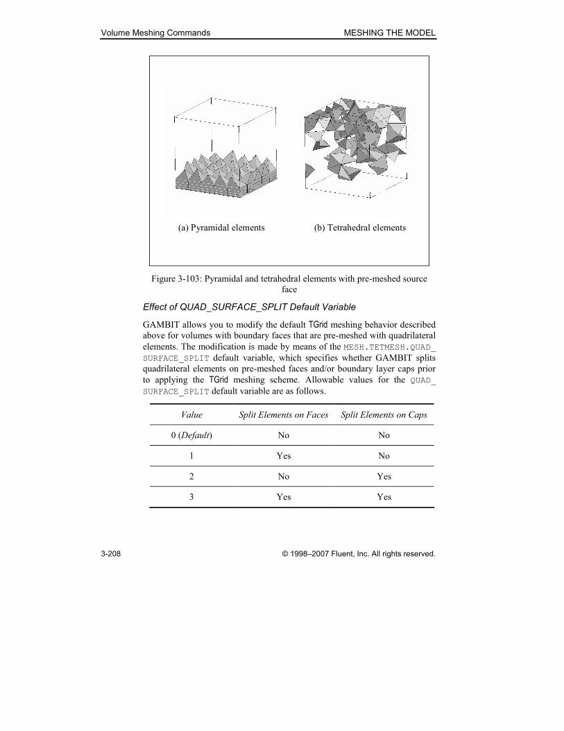
Volume Meshing Commands MESHING THE MODEL
3-208 © 1998–2007 Fluent, Inc. All rights reserved.
(a) Pyramidal elements (b) Tetrahedral elements
Figure 3-103: Pyramidal and tetrahedral elements with pre-meshed source
face
Effect of QUAD_SURFACE_SPLIT Default Variable
GAMBIT allows you to modify the default TGrid meshing behavior described
above for volumes with boundary faces that are pre-meshed with quadrilateral
elements. The modification is made by means of the MESH.TETMESH.QUAD_
SURFACE_SPLIT default variable, which specifies whether GAMBIT splits
quadrilateral elements on pre-meshed faces and/or boundary layer caps prior
to applying the TGrid meshing scheme. Allowable values for the QUAD_
SURFACE_SPLIT default variable are as follows.
Value Split Elements on Faces Split Elements on Caps
0 (Default) No No
1 Yes No
2 No Yes
3 Yes Yes
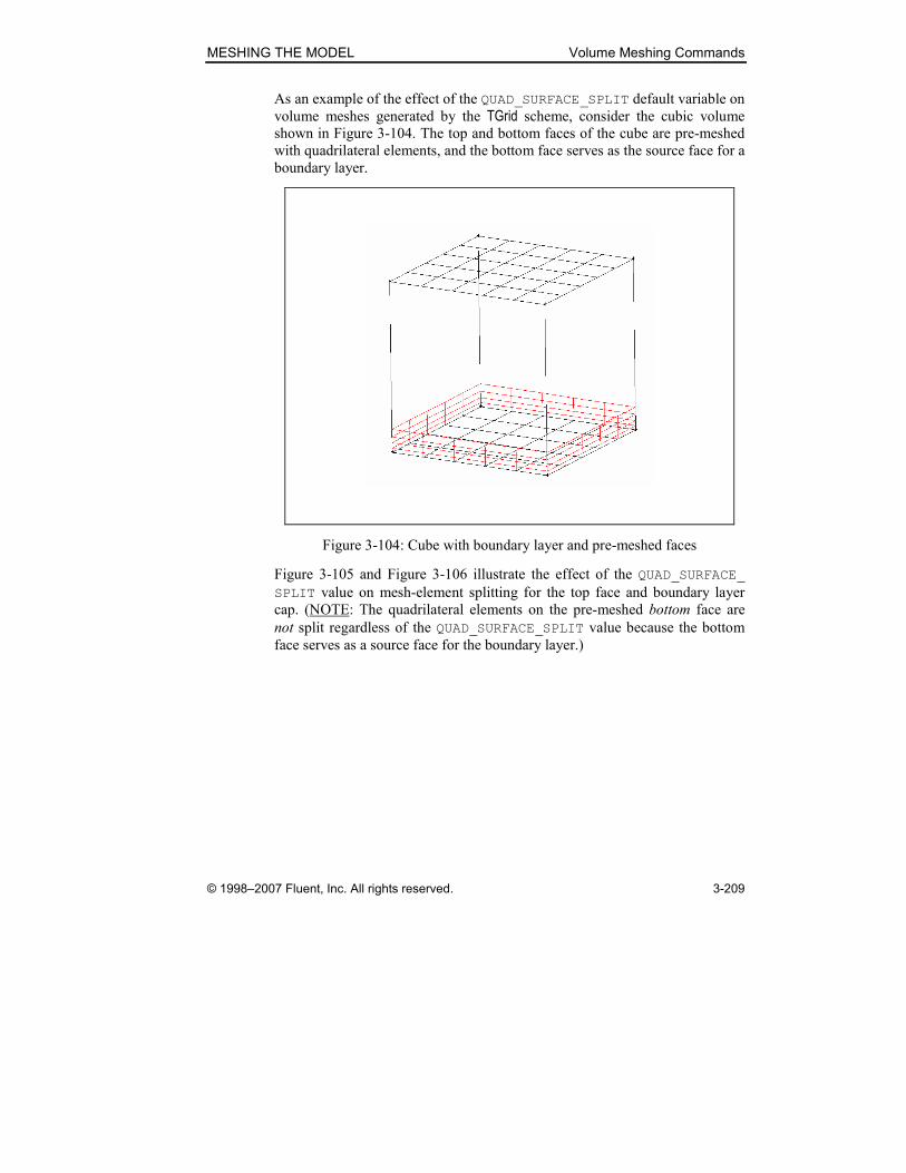
MESHING THE MODEL Volume Meshing Commands
© 1998–2007 Fluent, Inc. All rights reserved. 3-209
As an example of the effect of the QUAD_SURFACE_SPLIT default variable on
volume meshes generated by the TGrid scheme, consider the cubic volume
shown in Figure 3-104. The top and bottom faces of the cube are pre-meshed
with quadrilateral elements, and the bottom face serves as the source face for a
boundary layer.
Figure 3-104: Cube with boundary layer and pre-meshed faces
Figure 3-105 and Figure 3-106 illustrate the effect of the QUAD_SURFACE_
SPLIT value on mesh-element splitting for the top face and boundary layer
cap. (NOTE: The quadrilateral elements on the pre-meshed bottom face are
not split regardless of the QUAD_SURFACE_SPLIT value because the bottom
face serves as a source face for the boundary layer.)

Volume Meshing Commands MESHING THE MODEL
3-210 © 1998–2007 Fluent, Inc. All rights reserved.
(a) QUAD_SURFACE_SPLIT = 0 (b) QUAD_SURFACE_SPLIT = 1
Figure 3-105: Effect of QUAD_SURFACE_SPLIT values 0 and 1
(a) QUAD_SURFACE_SPLIT = 2 (b) QUAD_SURFACE_SPLIT = 3
Figure 3-106: Effect of QUAD_SURFACE_SPLIT values 2 and 3
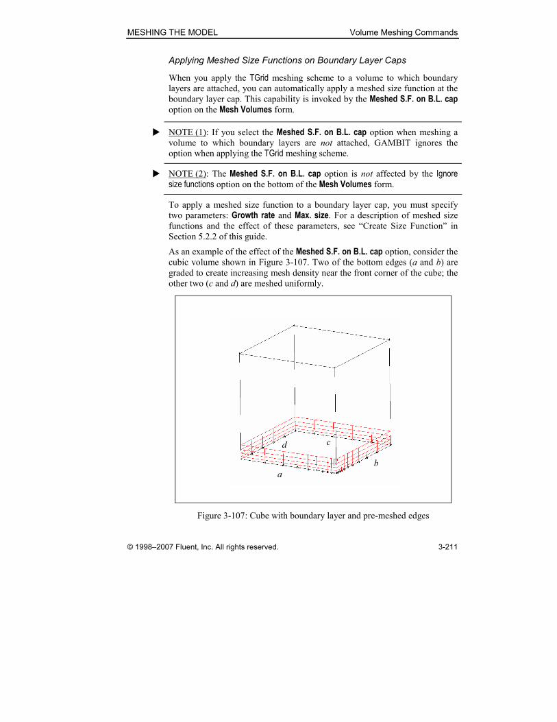
MESHING THE MODEL Volume Meshing Commands
© 1998–2007 Fluent, Inc. All rights reserved. 3-211
Applying Meshed Size Functions on Boundary Layer Caps
When you apply the TGrid meshing scheme to a volume to which boundary
layers are attached, you can automatically apply a meshed size function at the
boundary layer cap. This capability is invoked by the Meshed S.F. on B.L. cap option on the Mesh Volumes form.
� NOTE (1): If you select the Meshed S.F. on B.L. cap option when meshing a
volume to which boundary layers are not attached, GAMBIT ignores the
option when applying the TGrid meshing scheme.
� NOTE (2): The Meshed S.F. on B.L. cap option is not affected by the Ignore size functions option on the bottom of the Mesh Volumes form.
To apply a meshed size function to a boundary layer cap, you must specify
two parameters: Growth rate and Max. size. For a description of meshed size
functions and the effect of these parameters, see “Create Size Function” in
Section 5.2.2 of this guide.
As an example of the effect of the Meshed S.F. on B.L. cap option, consider the cubic volume shown in Figure 3-107. Two of the bottom edges (a and b) are
graded to create increasing mesh density near the front corner of the cube; the
other two (c and d) are meshed uniformly.
a
d c
b
Figure 3-107: Cube with boundary layer and pre-meshed edges

Volume Meshing Commands MESHING THE MODEL
3-212 © 1998–2007 Fluent, Inc. All rights reserved.
Figure 3-108 illustrates the effect of the S.F. on B.L. cap option on the TGrid volume mesh. For this example, the effect can be summarized as follows.
• If you do not select the S.F. on B.L. cap option, the TGrid scheme gener-
ates a mesh that includes highly skewed elements above the boundary
layer cap near the front corner of the cube (see Figure 3-108(a)).
• If you select the S.F. on B.L. cap option, the TGrid scheme generates a
mesh such as that shown in Figure 3-108(b), the elements of which are
well-formed in the front corner region above the boundary layer cap.
(a) No size function (b) Size function
Figure 3-108: Effect of S.F. on B.L. cap option
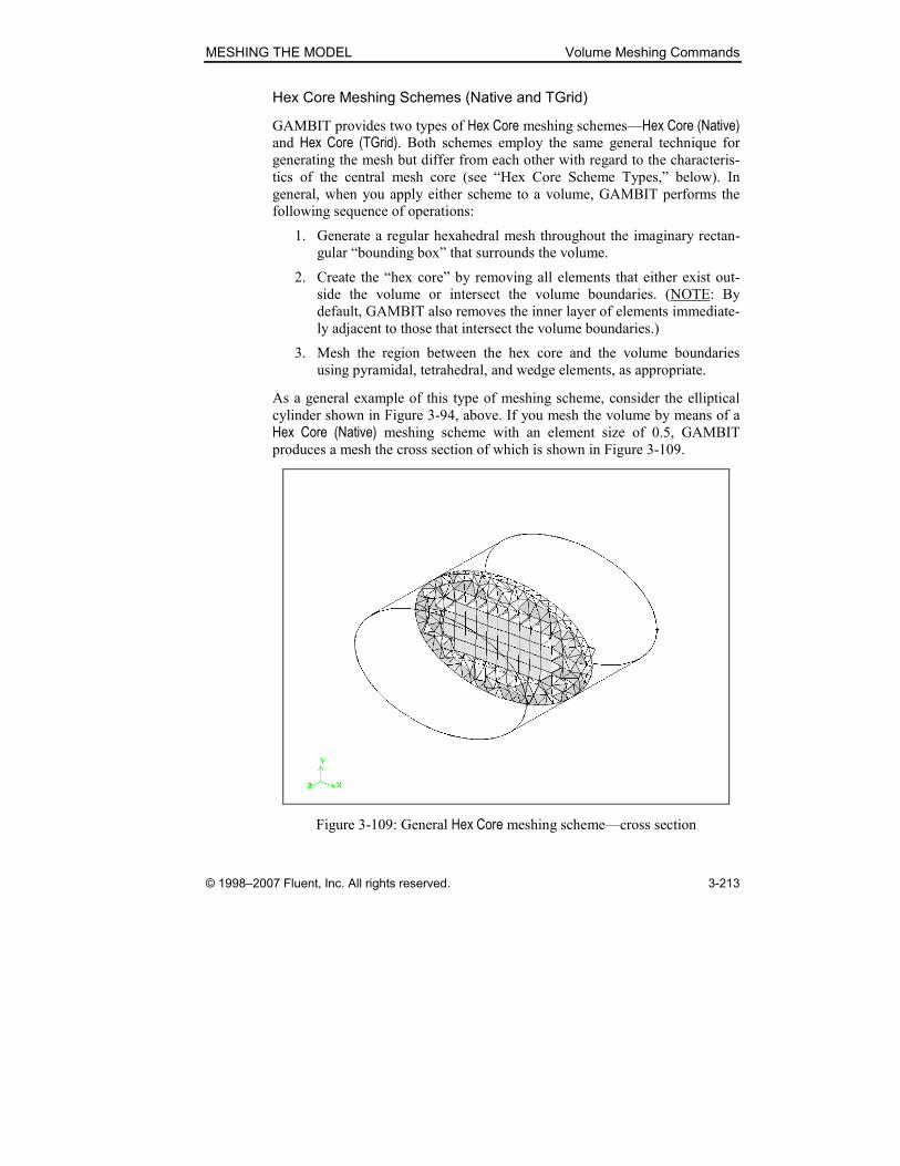
MESHING THE MODEL Volume Meshing Commands
© 1998–2007 Fluent, Inc. All rights reserved. 3-213
Hex Core Meshing Schemes (Native and TGrid)
GAMBIT provides two types of Hex Core meshing schemes—Hex Core (Native) and Hex Core (TGrid). Both schemes employ the same general technique for
generating the mesh but differ from each other with regard to the characteris-
tics of the central mesh core (see “Hex Core Scheme Types,” below). In
general, when you apply either scheme to a volume, GAMBIT performs the
following sequence of operations:
1. Generate a regular hexahedral mesh throughout the imaginary rectan-
gular “bounding box” that surrounds the volume.
2. Create the “hex core” by removing all elements that either exist out-
side the volume or intersect the volume boundaries. (NOTE: By
default, GAMBIT also removes the inner layer of elements immediate-
ly adjacent to those that intersect the volume boundaries.)
3. Mesh the region between the hex core and the volume boundaries
using pyramidal, tetrahedral, and wedge elements, as appropriate.
As a general example of this type of meshing scheme, consider the elliptical
cylinder shown in Figure 3-94, above. If you mesh the volume by means of a
Hex Core (Native) meshing scheme with an element size of 0.5, GAMBIT
produces a mesh the cross section of which is shown in Figure 3-109.
Figure 3-109: General Hex Core meshing scheme—cross section

Volume Meshing Commands MESHING THE MODEL
3-214 © 1998–2007 Fluent, Inc. All rights reserved.
The mesh shown in Figure 3-109 consists of a core of hexahedral elements
surrounded by a transition region of pyramidal elements adjacent to the core
itself and a shell of tetrahedral elements filling the remainder of the volume.
The existence of the hex core significantly reduces the total number of mesh
elements relative to that of a purely tetrahedral mesh.
Effect of Internal Dangling Faces
If the volume to be meshed includes an internal dangling face, GAMBIT
treats the face as a boundary face with respect to construction of the hex core.
That is, GAMBIT constructs the mesh such that layers of pyramidal and
tetrahedral elements can exist between the core and the dangling face. Figure
3-110 illustrates the effect of an internal dangling face for the mesh core of the
elliptical cylinder shown in Figure 3-109, above.
Dangling face
(a) Original core (b) Core with dangling face
Figure 3-110: General Hex Core meshing scheme—with internal dangling face

MESHING THE MODEL Volume Meshing Commands
© 1998–2007 Fluent, Inc. All rights reserved. 3-215
Hex Core Scheme Types
As noted above, GAMBIT provides two types of Hex Core meshing schemes:
• Hex Core (Native)—GAMBIT native scheme
• Hex Core (TGrid)—TGrid scheme
Each scheme type includes its own set of options that allow you to control
mesh characteristics. The specific effects of each method vary according to
the geometry of the volume(s) being meshed.
Hex Core (Native) Scheme
The Hex Core (Native) meshing scheme produces a core of uniformly sized
hexahedral elements surrounded by pyramidal and/or tetrahedral elements.
Specification of the Hex Core (Native) scheme involves the following para-
meters:
• Offset layers value
• Quad surface split option
• Allow hanging nodes option
The Offset layers value allows you to control the size of the hex core. The Quad surface split and Allow hanging nodes options affect characteristics of both the hex core and the surrounding mesh.
Offset layers Value
As noted above, GAMBIT creates the core of a hex-core mesh by generating a
hexahedral mesh throughout the volume “bounding box” and removing the
elements that either exist outside or intersect the volume boundaries. In
addition, GAMBIT removes at least one inner layer of elements immediately
adjacent to those that intersect the volume boundaries. When using the Hex Core (Native) scheme, you can specify the removal of additional element layers
by means of the Offset layers value.
As an example of the effect of the Offset layers specification, consider the two hex cores shown in Figure 3-111. Both hex cores are generated by meshing a
conical cylinder using the Hex Core (Native) scheme. They differ from each
other only with regard to their Offset layers values.

Volume Meshing Commands MESHING THE MODEL
3-216 © 1998–2007 Fluent, Inc. All rights reserved.
(a) Offset layers = 2 (b) Offset layers = 3
Figure 3-111: Effect of Offset layers value on conical cylinder hex cores
The hex core shown in Figure 3-111(a) is larger than that of Figure 3-111(b)
because fewer of its outer layers have been removed in the mesh generation
process.
� NOTE: The Offset layers value must be greater than or equal to two (2), so
that the mesh can include both tetrahedral elements adjacent to the volume
boundaries and pyramidal elements in the surrounding region.
Quad surface split Option
The Quad surface split option allows you to control the types of face elements
created on the hex-core boundary. If you select the option, GAMBIT splits
(diagonally) all quadrilateral face elements on the hex-core boundary, thereby
replacing them with triangular elements. As a result, the mesh created adja-
cent to the hex-core boundary contains tetrahedral elements rather than the
pyramidal elements that would be created if the quadrilateral face elements
were not split. (NOTE: If you do not select the Quad surface split option, GAMBIT may still split some hex-core boundary elements when generating
the mesh.)
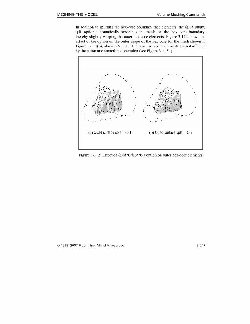
MESHING THE MODEL Volume Meshing Commands
© 1998–2007 Fluent, Inc. All rights reserved. 3-217
In addition to splitting the hex-core boundary face elements, the Quad surface split option automatically smoothes the mesh on the hex core boundary,
thereby slightly warping the outer hex-core elements. Figure 3-112 shows the
effect of the option on the outer shape of the hex core for the mesh shown in
Figure 3-111(b), above. (NOTE: The inner hex-core elements are not affected
by the automatic smoothing operation (see Figure 3-113).)
(a) Quad surface split = Off (b) Quad surface split = On
Figure 3-112: Effect of Quad surface split option on outer hex-core elements
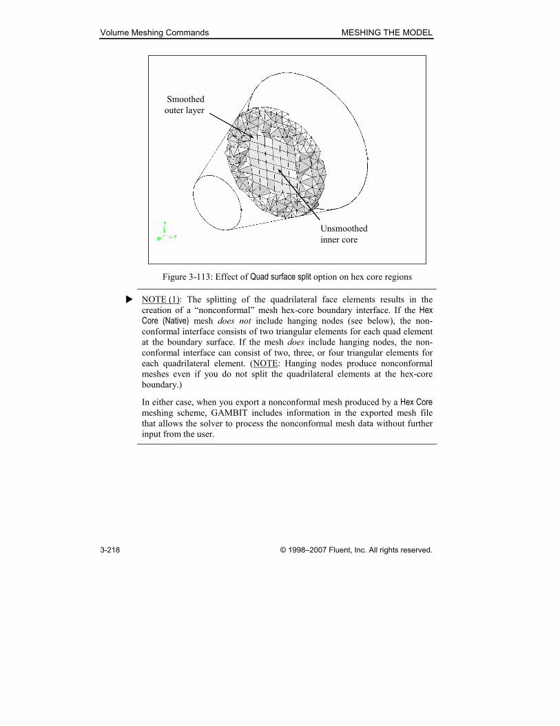
Volume Meshing Commands MESHING THE MODEL
3-218 © 1998–2007 Fluent, Inc. All rights reserved.
Smoothed
outer layer
Unsmoothed
inner core
Figure 3-113: Effect of Quad surface split option on hex core regions
� NOTE (1): The splitting of the quadrilateral face elements results in the
creation of a “nonconformal” mesh hex-core boundary interface. If the Hex Core (Native) mesh does not include hanging nodes (see below), the non-
conformal interface consists of two triangular elements for each quad element
at the boundary surface. If the mesh does include hanging nodes, the non-
conformal interface can consist of two, three, or four triangular elements for
each quadrilateral element. (NOTE: Hanging nodes produce nonconformal
meshes even if you do not split the quadrilateral elements at the hex-core
boundary.)
In either case, when you export a nonconformal mesh produced by a Hex Core meshing scheme, GAMBIT includes information in the exported mesh file
that allows the solver to process the nonconformal mesh data without further
input from the user.
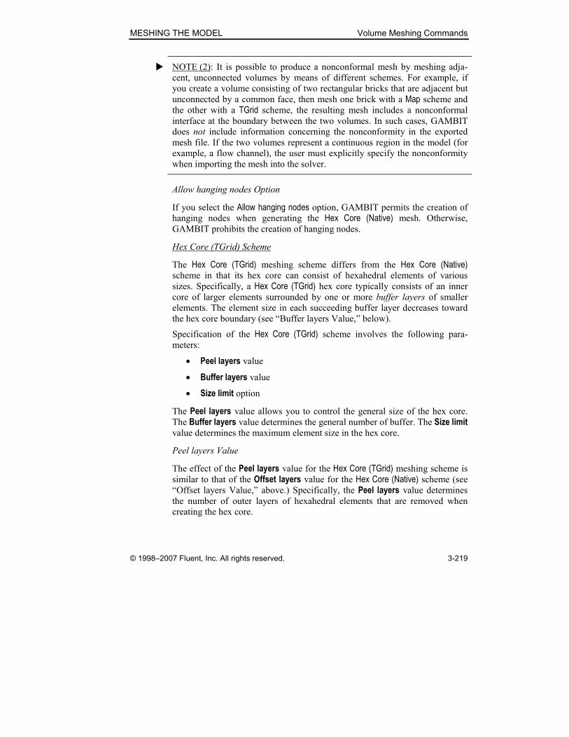
MESHING THE MODEL Volume Meshing Commands
© 1998–2007 Fluent, Inc. All rights reserved. 3-219
� NOTE (2): It is possible to produce a nonconformal mesh by meshing adja-
cent, unconnected volumes by means of different schemes. For example, if
you create a volume consisting of two rectangular bricks that are adjacent but
unconnected by a common face, then mesh one brick with a Map scheme and
the other with a TGrid scheme, the resulting mesh includes a nonconformal
interface at the boundary between the two volumes. In such cases, GAMBIT
does not include information concerning the nonconformity in the exported
mesh file. If the two volumes represent a continuous region in the model (for
example, a flow channel), the user must explicitly specify the nonconformity
when importing the mesh into the solver.
Allow hanging nodes Option
If you select the Allow hanging nodes option, GAMBIT permits the creation of
hanging nodes when generating the Hex Core (Native) mesh. Otherwise,
GAMBIT prohibits the creation of hanging nodes.
Hex Core (TGrid) Scheme
The Hex Core (TGrid) meshing scheme differs from the Hex Core (Native) scheme in that its hex core can consist of hexahedral elements of various
sizes. Specifically, a Hex Core (TGrid) hex core typically consists of an inner core of larger elements surrounded by one or more buffer layers of smaller
elements. The element size in each succeeding buffer layer decreases toward
the hex core boundary (see “Buffer layers Value,” below).
Specification of the Hex Core (TGrid) scheme involves the following para-
meters:
• Peel layers value
• Buffer layers value
• Size limit option
The Peel layers value allows you to control the general size of the hex core. The Buffer layers value determines the general number of buffer. The Size limit value determines the maximum element size in the hex core.
Peel layers Value
The effect of the Peel layers value for the Hex Core (TGrid) meshing scheme is
similar to that of the Offset layers value for the Hex Core (Native) scheme (see
“Offset layers Value,” above.) Specifically, the Peel layers value determines
the number of outer layers of hexahedral elements that are removed when
creating the hex core.

Volume Meshing Commands MESHING THE MODEL
3-220 © 1998–2007 Fluent, Inc. All rights reserved.
Buffer layers Value
As noted above, a Hex Core (TGrid) hex core typically consists of an inner core of larger elements surrounded by one or more buffer layers of smaller
elements. The Buffer layers value allows you to specify (generally) the number
of buffer layers and to thereby influence the shape and characteristics of the
hex core.
As an example of the effect of the Buffer layers value on a Hex Core (TGrid) mesh, consider the volume shown in Figure 3-114, the geometry of which
represents a catalytic converter. The mesh cross sections shown in Figure
3-115 illustrate the general effect of the Buffer layers value on the character-istics of the hex core for this example.
Figure 3-114: Catalytic converter volume
MESHING THE MODEL Volume Meshing Commands
© 1998–2007 Fluent, Inc. All rights reserved. 3-221
(a) Buffer layers = 0 (b) Buffer layers = 2
Figure 3-115: Hex Core cross section—effect of Buffer layers value
Size limit Value
The Size limit value determines the maximum element size in the hex core.
GAMBIT provides two Size limit options:
• Auto—Uses the Spacing:Interval size value as the hex core size limit
• Manual—Allows you to specify the Size limit value
If you select the Manual option and specify a Size limit of 0, GAMBIT uses an
internal default TGrid hexcore size-limit value; otherwise, GAMBIT uses the
user-specified Size limit value.
Figure 3-116 illustrates the general effect of the Size limit value on the hex core characteristics for the catalytic-converter geometry shown in Figure
3-114, above.

Volume Meshing Commands MESHING THE MODEL
3-222 © 1998–2007 Fluent, Inc. All rights reserved.
(a) Size limit = 5 (b) Size limit = 10
Figure 3-116: Hex Core cross section—effect of Size limit value
Specifying the Element Size
The procedures outlined above require that the specified element size is small
enough to allow both the creation of a hexahedral core and two layers of ele-
ments (pyramidal and tetrahedral) surrounding the core. If you specify an
element size that is too large to accommodate both the core and the transition
layers, GAMBIT meshes the volume using only tetrahedral elements. For
example, if you employ the Hex Core (Native) meshing scheme for the elliptical
cylinder shown in Figure 3-94, above, and specify an element size of 1,
GAMBIT creates a mesh the cross section of which is shown in Figure 3-117.

MESHING THE MODEL Volume Meshing Commands
© 1998–2007 Fluent, Inc. All rights reserved. 3-223
Figure 3-117: Hex Core (Native) meshing scheme—element size = 1
General Applicability
The Hex Core (Native) and Hex Core (TGrid) meshing schemes are applicable to
all volumes but is useful mainly for volumes with large internal regions and
few internal boundaries such as intrusions or holes.
Specifying Volume Meshing Options
GAMBIT includes the following universal options on the Mesh Volumes form:
• Mesh
• Remove old mesh
• Remove lower mesh
• Ignore size functions
Mesh Option
If you select the Mesh option, GAMBIT meshes the picked volume(s) accord-
ing to the parameters as currently specified on the Mesh Volumes form. If you
Apply the meshing specifications without selecting the Mesh option, GAMBIT
applies the currently specified mesh parameters to the volume(s) but does not
create the mesh.

Volume Meshing Commands MESHING THE MODEL
3-224 © 1998–2007 Fluent, Inc. All rights reserved.
Remove old mesh Option
If you select the Remove old mesh option, GAMBIT removes any currently
existing mesh from the specified volume(s) before creating the new volume
mesh(es). GAMBIT also enables the Remove lower mesh option (see below), which specifies whether or not to remove the mesh on the volume boundary
faces and edges. If you do not select the Remove lower mesh option, GAMBIT
retains the existing lower-topology mesh(es) when meshing the volume.
Remove lower mesh Option
As noted above, when you select the Remove old mesh option, GAMBIT
enables the Remove lower mesh option, which allows you to specify whether or not to remove any existing mesh(es) on the boundary faces and edges of the
volume(s) to be meshed.
• If you select the Remove lower mesh option, GAMBIT removes any
existing boundary face or edge meshes before remeshing the volume
(unless they are associated with other meshed topology)..
• If you do not select the Remove lower mesh option, GAMBIT retains
the existing boundary face and edge mesh(es) when remeshing the
volume.
Ignore size functions Option
If you select the Ignore size functions option, GAMBIT ignores any existing
size function specifications that would otherwise affect the volume mesh.
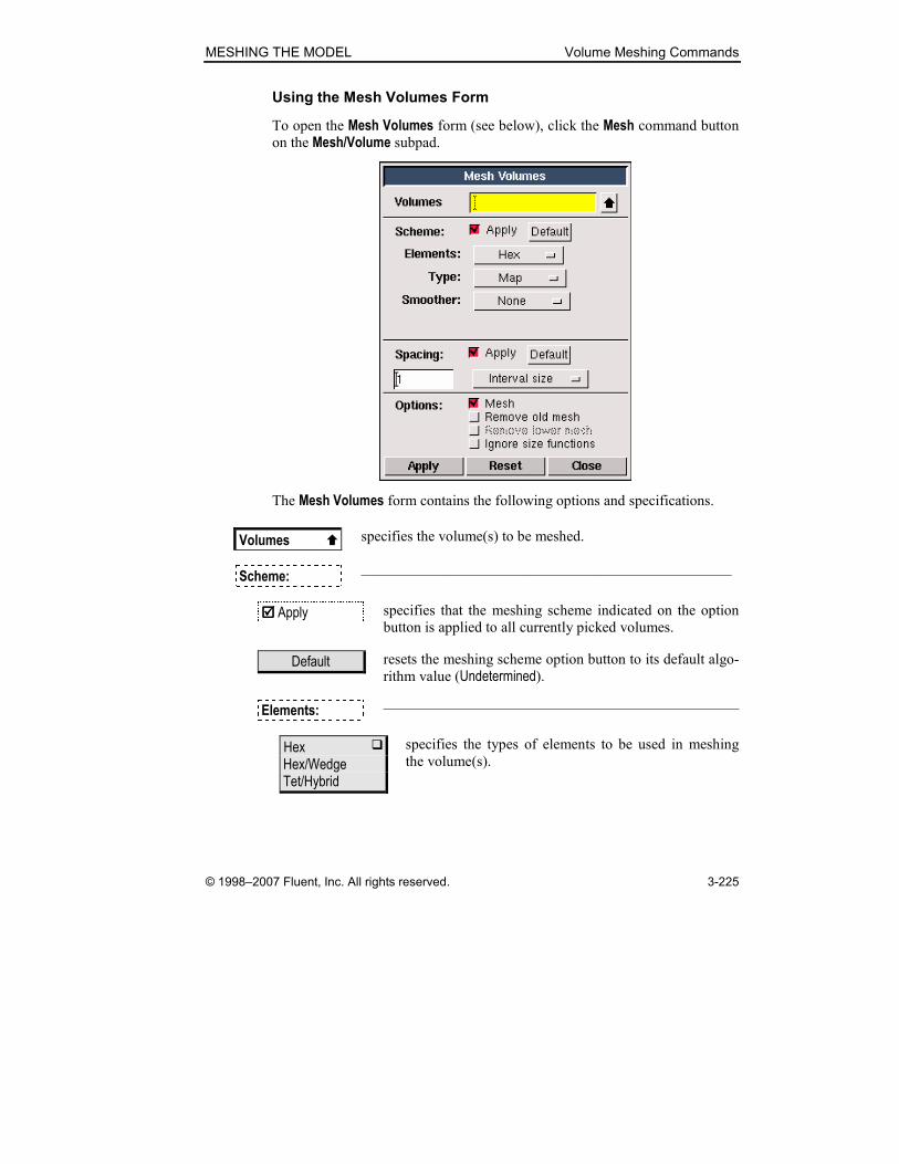
MESHING THE MODEL Volume Meshing Commands
© 1998–2007 Fluent, Inc. All rights reserved. 3-225
Using the Mesh Volumes Form
To open the Mesh Volumes form (see below), click the Mesh command button
on the Mesh/Volume subpad.
The Mesh Volumes form contains the following options and specifications.
Volumes � specifies the volume(s) to be meshed.
Scheme: —————————————————————————
���� Apply specifies that the meshing scheme indicated on the option
button is applied to all currently picked volumes.
Default resets the meshing scheme option button to its default algo-
rithm value (Undetermined).
Elements: ————————————————————————
Hex � Hex/Wedge Tet/Hybrid
specifies the types of elements to be used in meshing
the volume(s).
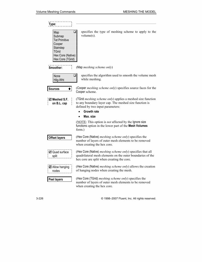
Volume Meshing Commands MESHING THE MODEL
3-226 © 1998–2007 Fluent, Inc. All rights reserved.
Type: ————————————————————————
Map � Submap Tet Primitive Cooper Stairstep TGrid Hex Core (Native) Hex Core (TGrid)
specifies the type of meshing scheme to apply to the
volume(s).
Smoother: (Map meshing scheme only)
None � Hilg-Wht
specifies the algorithm used to smooth the volume mesh
while meshing.
Sources � (Cooper meshing scheme only) specifies source faces for the Cooper scheme.
���� Meshed S.F. on B.L. cap
(TGrid meshing scheme only) applies a meshed size function
to any boundary layer cap. The meshed size function is
defined by two input parameters:
• Growth rate
• Max. size
(NOTE: This option is not affected by the Ignore size functions option in the lower part of the Mesh Volumes form.)
Offset layers (Hex Core (Native) meshing scheme only) specifies the number of layers of outer mesh elements to be removed
when creating the hex core.
���� Quad surface split
(Hex Core (Native) meshing scheme only) specifies that all quadrilateral mesh elements on the outer boundaries of the
hex core are split when creating the core.
���� Allow hanging nodes
(Hex Core (Native) meshing scheme only) allows the creation of hanging nodes when creating the mesh.
Peel layers (Hex Core (TGrid) meshing scheme only) specifies the number of layers of outer mesh elements to be removed
when creating the hex core.

MESHING THE MODEL Volume Meshing Commands
© 1998–2007 Fluent, Inc. All rights reserved. 3-227
Buffer layers (Hex Core (TGrid) meshing scheme only) specifies the number of buffer layers to use for the Hex Core (TGrid) scheme.
Size limit (Hex Core (TGrid) meshing scheme only) specifies the size limit for hex-core elements. The Size limit option includes two suboptions:
• Auto—Uses the Spacing:Interval size value as the size limit
• Manual—Uses a user-defined size limit
Spacing: —————————————————————————
���� Apply specifies that the current mesh node spacing parameters are
applied to all currently specified volume(s).
Default resets the mesh node spacing parameters to their default
values.
Value specifies the numerical component of the mesh node spac-
ing parameters.
Interval size � Interval count Shortest edge (%)
specifies the measurement unit for the mesh node spacing
parameters.
Options —————————————————————————
���� Mesh specifies that a new mesh is created in the specified
volume(s).
���� Remove old mesh
specifies the removal of any current mesh that is associated
with the specified volume(s) and created by means of the
Mesh Volumes form.
���� Remove lower mesh
specifies that all lower-topology (face and edge) meshes
associated with the specified volume(s) are removed when
the volume mesh is removed unless they are associated
with other meshed topology.

Volume Meshing Commands MESHING THE MODEL
3-228 © 1998–2007 Fluent, Inc. All rights reserved.
���� Ignore size functions
specifies that GAMBIT ignores any existing size-function
specifications that would otherwise affect the volume mesh.
(NOTE: This option does not affect the operation of the
Meshed S.F. on B.L. cap option for the TGrid meshing
scheme.)
MESHING THE MODEL Volume Meshing Commands
© 1998–2007 Fluent, Inc. All rights reserved. 3-229
3.4.2 Smooth Volume Meshes
The Smooth Volume Meshes operation (volume smooth command)
smoothes the spacing of mesh nodes throughout one or more volumes. When
you smooth a volume mesh, GAMBIT automatically adjusts mesh node loca-
tions in order to improve the uniformity of spacing between nodes throughout
the mesh. To smooth a volume mesh, you must specify the following para-
meters:
• The volume for which the mesh is to be smoothed
• The smoothing scheme
Specifying the Smoothing Scheme
GAMBIT provides the following mesh smoothing schemes:
• Length-weighted Laplacian (L-W Laplacian)
• Equipotential (Equipotential)
The following table summarizes the basic features of the algorithms employed
by each scheme.
Algorithm Features
Length-weighted Laplacian Uses the average edge length of the elements
surrounding each node
Equipotential Adjusts node locations to equalize the vol-
umes of the mesh elements surrounding each
node
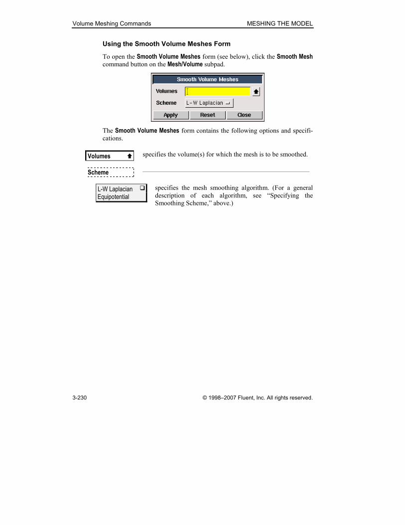
Volume Meshing Commands MESHING THE MODEL
3-230 © 1998–2007 Fluent, Inc. All rights reserved.
Using the Smooth Volume Meshes Form
To open the Smooth Volume Meshes form (see below), click the Smooth Mesh command button on the Mesh/Volume subpad.
The Smooth Volume Meshes form contains the following options and specifi-
cations.
Volumes � specifies the volume(s) for which the mesh is to be smoothed.
Scheme —————————————————————————
L-W Laplacian � Equipotential
specifies the mesh smoothing algorithm. (For a general
description of each algorithm, see “Specifying the
Smoothing Scheme,” above.)

MESHING THE MODEL Volume Meshing Commands
© 1998–2007 Fluent, Inc. All rights reserved. 3-231
3.4.3 Set Volume Element Type
The Volume Element Type operation (default set command for the
MESH.NODES.HEX default variable) specifies the number of mesh nodes and
the node pattern associated with any of four available volume element shapes.
To set the volume element type, you must specify the numbers of nodes asso-
ciated with each of the volume element shapes. There are four volume ele-
ment shapes available in GAMBIT:
• Hexahedron
• Wedge
• Tetrahedron
• Pyramid
Every volume element shape is associated with as many as five different node
patterns. Each node pattern is characterized by the number of nodes in the
pattern. The node patterns associated with each volume element shape are as
follows:
Shape Numbers of Nodes
Hexahedron 8, 20, 27
Wedge 6, 15, 18
Tetrahedron 4, 10
Pyramid 5, 13, 14
When you set a volume element type, GAMBIT applies the specified mesh
node pattern to all volume elements of the specified shape. For example, if
you specify 20-node wedge volume elements, GAMBIT locates mesh nodes
according to the 20-node pattern for all wedge volume elements produced in
the subsequent volume meshing operation.
Figure 3-118, Figure 3-119, Figure 3-120, and Figure 3-121 show the place-
ment of nodes for each of the node patterns listed above.
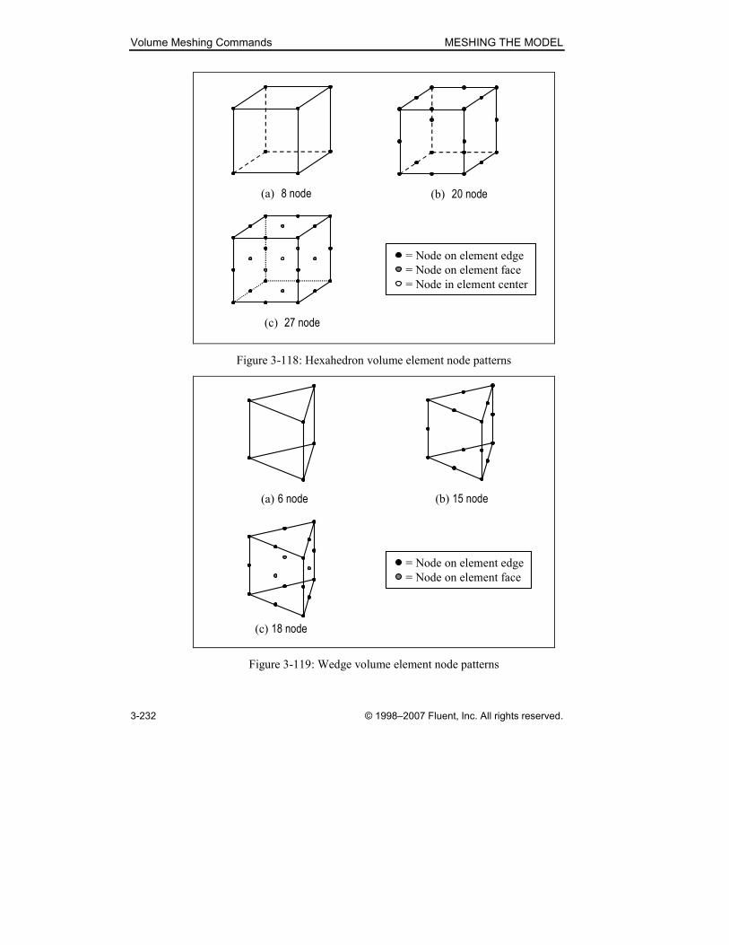
Volume Meshing Commands MESHING THE MODEL
3-232 © 1998–2007 Fluent, Inc. All rights reserved.
(a) 8 node (b) 20 node
(c) 27 node
= Node on element edge
= Node on element face
= Node in element center
Figure 3-118: Hexahedron volume element node patterns
(a) 6 node (b) 15 node
(c) 18 node
= Node on element edge
= Node on element face
Figure 3-119: Wedge volume element node patterns
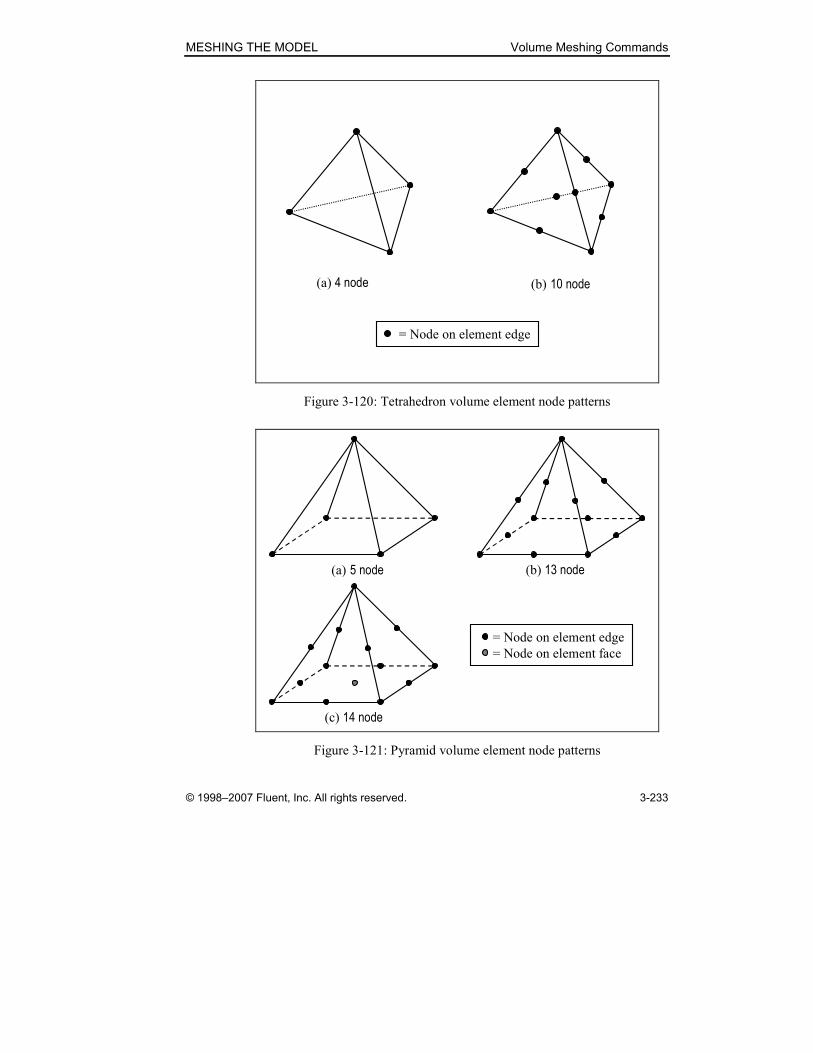
MESHING THE MODEL Volume Meshing Commands
© 1998–2007 Fluent, Inc. All rights reserved. 3-233
(a) 4 node (b) 10 node
= Node on element edge
Figure 3-120: Tetrahedron volume element node patterns
(a) 5 node (b) 13 node
(c) 14 node
= Node on element edge
= Node on element face
Figure 3-121: Pyramid volume element node patterns

Volume Meshing Commands MESHING THE MODEL
3-234 © 1998–2007 Fluent, Inc. All rights reserved.
Using the Set Volume Element Type Form
To open the Set Volume Element Type form (see below), click the Set Volume Element Type command button on the Mesh/Volume subpad.
The Set Volume Element Type form contains the following specifications.
Hexahedron specifies the hexahedron volume element type: 8 node, 20 node, or 27 node.
Wedge specifies the wedge volume element type: 6 node, 15 node, or 18 node.
Tetrahedron specifies the tetrahedron volume element type: 4 node or 10 node.
Pyramid specifies the pyramid volume element type: 5 node, 13 node, or 14 node.
MESHING THE MODEL Volume Meshing Commands
© 1998–2007 Fluent, Inc. All rights reserved. 3-235
3.4.4 Link/Unlink Volume Meshes
The Link/Unlink Volume Meshes command button allows you to perform the
following operations.
Symbol Command Description
Link Volume Meshes Creates hard links between volumes
Unlink Volume Meshes Deletes hard links between volumes
The following sections describe the procedures and specifications required to
execute the operations listed above.

Volume Meshing Commands MESHING THE MODEL
3-236 © 1998–2007 Fluent, Inc. All rights reserved.
Link Volume Meshes
The Link Volume Meshes operation (volume link command) creates a hard
link between two volumes. When you mesh a volume that is hard-linked to
another volume, GAMBIT applies identical mesh parameters to both volumes.
� NOTE: When you select a volume for the Link Volume Meshes operation, GAMBIT automatically highlights the graphic display of any volumes to
which the volume is currently linked.
The volumes to be linked must satisfy the following criteria:
• They must be topologically identical to each other.
• The corresponding faces of each volume must be hard-linked to each
other prior to execution of the Link Volume Meshes command.
As an example of the second criterion listed above, consider the two cylindri-
cal volumes shown in Figure 3-122. The volumes are topologically identical
and differ from each other geometrically only with respect to their cross-
sectional dimensions.
volume.1 volume.2
face.2
face.3
face.1
face.5
face.6face.4
Figure 3-122: Example volumes to be hard-linked
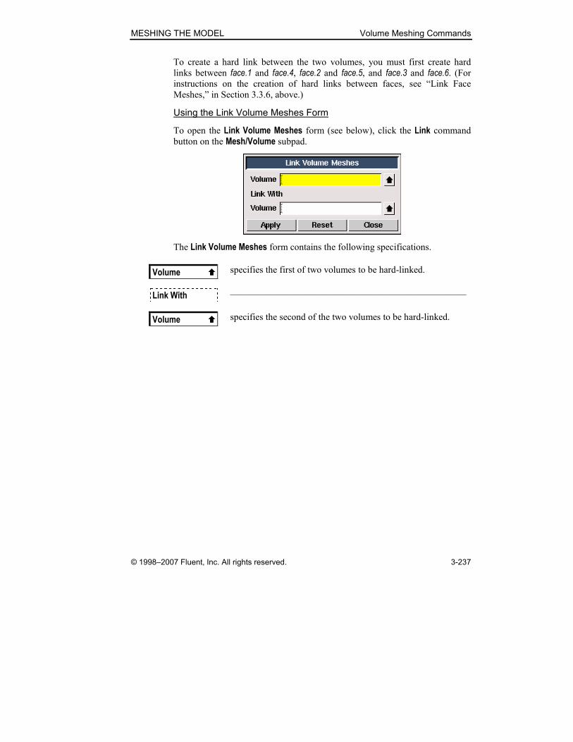
MESHING THE MODEL Volume Meshing Commands
© 1998–2007 Fluent, Inc. All rights reserved. 3-237
To create a hard link between the two volumes, you must first create hard
links between face.1 and face.4, face.2 and face.5, and face.3 and face.6. (For instructions on the creation of hard links between faces, see “Link Face
Meshes,” in Section 3.3.6, above.)
Using the Link Volume Meshes Form
To open the Link Volume Meshes form (see below), click the Link command
button on the Mesh/Volume subpad.
The Link Volume Meshes form contains the following specifications.
Volume � specifies the first of two volumes to be hard-linked.
Link With —————————————————————————
Volume � specifies the second of the two volumes to be hard-linked.

Volume Meshing Commands MESHING THE MODEL
3-238 © 1998–2007 Fluent, Inc. All rights reserved.
Unlink Volume Meshes
The Unlink Volume Meshes operation (volume unlink command) deletes
hard mesh links associated with one or more volumes.
� NOTE: When you select a volume for the Unlink Volume Meshes operation, GAMBIT automatically highlights the graphic display of any volumes to
which the volume is currently linked.
Using the Unlink Volume Meshes Form
To open the Unlink Volume Meshes form (see below), click the Unlink com-
mand button on the Mesh/Volume subpad.
The Unlink Volume Meshes form contains the following options and specifica-
tions.
Volumes � specifies the volumes between which the link is to be deleted.
���� Lower topology
unlinks all lower-topology entities that are associated with the
specified volumes.

MESHING THE MODEL Volume Meshing Commands
© 1998–2007 Fluent, Inc. All rights reserved. 3-239
3.4.5 Modify Meshed Volume
The Modify Meshed Volume operation (volume split edgenodes com-
mand) converts mesh edges on the exterior faces of a meshed volume to
topological edges and creates faceted faces where appropriate. For a descrip-
tion of the procedures and specifications involved in creating a conversion list,
see “Modify Meshed Face,” in Section 3.3.7, above.
� NOTE: When GAMBIT executes the Modify Meshed Volume command, the
original meshed volume is deleted.
Using the Modify Meshed Volume Form
To open the Modify Meshed Volume form (see below), click the Modify Meshed Volume command button on the Mesh/Volume subpad.
For a general description of the procedures and specifications involved in
using the Modify Meshed Volume form, see “Using the Modify Meshed Face
Form,” in Section 3.3.7, above.
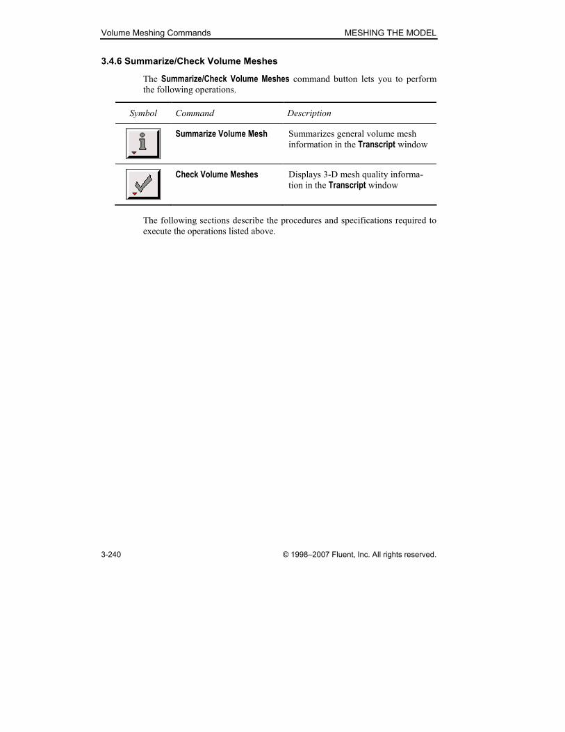
Volume Meshing Commands MESHING THE MODEL
3-240 © 1998–2007 Fluent, Inc. All rights reserved.
3.4.6 Summarize/Check Volume Meshes
The Summarize/Check Volume Meshes command button lets you to perform
the following operations.
Symbol Command Description
Summarize Volume Mesh Summarizes general volume mesh
information in the Transcript window
Check Volume Meshes Displays 3-D mesh quality informa-
tion in the Transcript window
The following sections describe the procedures and specifications required to
execute the operations listed above.

MESHING THE MODEL Volume Meshing Commands
© 1998–2007 Fluent, Inc. All rights reserved. 3-241
Summarize Volume Mesh
The Summarize Volume Mesh operation (volume msummarize command)
displays volume mesh information in the Transcript window and allows you to highlight specific mesh nodes and/or mesh elements in the graphics window.
(NOTE: For a general description of the GAMBIT mesh summary functional-
ity, see “Summarize Face Mesh,” in Section 3.3.8, above.)
Using the Summarize Volume Mesh Form
To open the Summarize Volume Mesh form (see below), click the Summarize command button on the Mesh/Volume subpad.
For a description of the use of the Summarize Volume Mesh form, see “Using
the Summarize Face Mesh Form,” in Section 3.3.8, above.

Volume Meshing Commands MESHING THE MODEL
3-242 © 1998–2007 Fluent, Inc. All rights reserved.
Check Volume Meshes
The Check Volume Meshes operation (volume check quality command)
displays 3-D mesh quality data. When you execute the Check Volume Meshes command, GAMBIT displays the following information elements in the
Transcript window:
• A table that summarizes 3-D mesh quality statistical information for
all volumes specified on the Check Volume Meshes form
• A summary statement that includes the numbers of specified volumes
that contain highly skewed and inverted elements
Tabular 3-D Mesh Quality Data
The Check Volume Meshes tabular output represents the statistical distribution of element mesh quality values for the current default 3-D quality metric.
Table 3.2 shows an example of such output for a volume mesh evaluated
according to the EquiAngle Skew quality metric. Output such as that shown in
Table 3.2 constitutes a numerical representation of the mesh quality histogram
that is displayed on the Examine Mesh form when you choose the Display Type:Range option (see Section 3.4.2 of the GAMBIT User’s Guide).
Table 3.2: Example Check Volume Meshes tabular output
Summarizing EQUIANGLE SKEW of 3D elements for 1 meshed volume:
Volume volume.1 meshed using Map scheme and size of 1.000000.
From value To value Count in range % of total count (1463)
--------------------------------------------------------------
0 0.1 286 19.55
0.1 0.2 671 45.86
0.2 0.3 341 23.31
0.3 0.4 88 6.02
0.4 0.5 66 4.51
0.5 0.6 11 0.75
0.6 0.7 0 0.00
0.7 0.8 0 0.00
0.8 0.9 0 0.00
0.9 1 0 0.00
--------------------------------------------------------------
0 1 1463 100.00
In addition to the tabular output shown in Table 3.2, the Check Volume Meshes command displays the minimum and maximum values of element quality for
the set of specified volumes. The minimum and maximum element quality
information is not available by means of any other GAMBIT operation.

MESHING THE MODEL Volume Meshing Commands
© 1998–2007 Fluent, Inc. All rights reserved. 3-243
Specifying the Quality Metric
As noted above, the Check Volume Meshes command evaluates mesh element
quality according to the current default 3-D mesh quality metric. To change
the metric used to evaluate element quality for the Check Volume Meshes com-
mand, you must modify the default 3-D mesh quality metric by means of the
Edit Defaults form. To do so:
1. Open the Edit Defaults form.
2. Click the MESH tab to open the MESH defaults subform.
3. Select the EXAMINE radio button to display the EXAMINE variables.
4. Modify the ELEMENT_3D_QUALITY variable.
(For a complete description of the procedures required to modify default vari-
ables by means of the Edit Defaults form, see Section 4.2.4 of the GAMBIT
User’s Guide.)
For example, to evaluate 3-D elements on the basis of the Aspect Ratio metric:
1. Use the procedure described above to set Aspect Ratio as the default
quality metric (ELEMENT_3D_QUALITY=2 )
2. Execute the Check Volume Meshes command.
� NOTE: Check Volume Meshes command tabular output, such as that shown in
Table 3.2, includes all 3-D elements that possess shapes for which the current
default quality metric applies. For example, if you specify EquiAngle Skew as the default 3-D quality metric, the tabular output includes all hexahedral,
tetrahedral, prism, and wedge elements associated with the volumes specified
on the Check Volume Meshes form. However, if you specify Aspect Ratio as the default 3-D quality metric, the tabular output includes only hexahedral and tet-
rahedral elements, because the Diagonal Ratio metric does not apply to prism or
wedge elements.
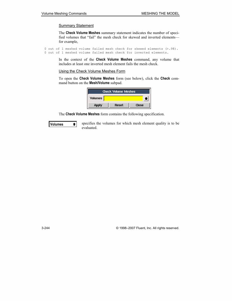
Volume Meshing Commands MESHING THE MODEL
3-244 © 1998–2007 Fluent, Inc. All rights reserved.
Summary Statement
The Check Volume Meshes summary statement indicates the number of speci-
fied volumes that “fail” the mesh check for skewed and inverted elements—
for example,
0 out of 1 meshed volume failed mesh check for skewed elements (>.98).
0 out of 1 meshed volume failed mesh check for inverted elements.
In the context of the Check Volume Meshes command, any volume that
includes at least one inverted mesh element fails the mesh check.
Using the Check Volume Meshes Form
To open the Check Volume Meshes form (see below), click the Check com-
mand button on the Mesh/Volume subpad.
The Check Volume Meshes form contains the following specification.
Volumes � specifies the volumes for which mesh element quality is to be
evaluated.

MESHING THE MODEL Volume Meshing Commands
© 1998–2007 Fluent, Inc. All rights reserved. 3-245
3.4.7 Delete Volume Meshes
The Delete Volume Meshes operation (volume delete onlymesh com-
mand) deletes the mesh from one or more volumes. When you delete a
volume mesh, GAMBIT allows you to retain or delete all face meshes and
edge meshes associated with the volume.
Using the Delete Volume Meshes Form
To open the Delete Volume Meshes form (see below), click the Delete com-
mand button on the Mesh/Volume subpad.
The Delete Volume Meshes form contains the following options and specifica-
tions.
Volumes � specifies the volume(s) for which the mesh is to be deleted.
All � Pick
• All specifies all volumes in the model.
• Pick specifies volumes selected by means of the
Volumes list box.
���� Remove unused lower mesh
removes all unused lower-topology meshes associated with
the specified volume(s).
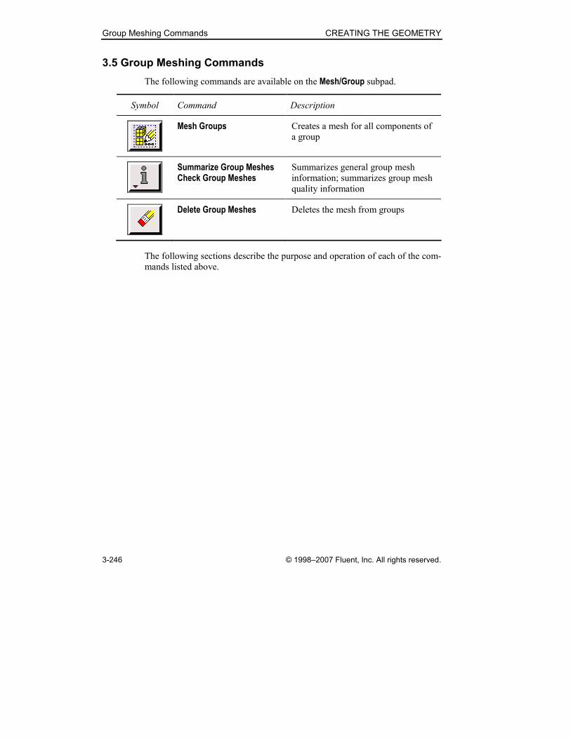
Group Meshing Commands CREATING THE GEOMETRY
3-246 © 1998–2007 Fluent, Inc. All rights reserved.
3.5 Group Meshing Commands
The following commands are available on the Mesh/Group subpad.
Symbol Command Description
Mesh Groups Creates a mesh for all components of
a group
Summarize Group Meshes Check Group Meshes
Summarizes general group mesh
information; summarizes group mesh
quality information
Delete Group Meshes Deletes the mesh from groups
The following sections describe the purpose and operation of each of the com-
mands listed above.

CREATING THE GEOMETRY Group Meshing Commands
© 1998–2007 Fluent, Inc. All rights reserved. 3-247
3.5.1 Mesh Groups
The Mesh Groups operation (group mesh and group modify commands)
activates meshing operations for one or more groups of topological entities.
Overview
When you mesh a group by means of the Mesh Groups command, GAMBIT
performs meshing operations for all of the topological entities that comprise
components of the group. If you apply meshing parameters to any or all com-
ponents of the group prior to executing the Mesh Groups command, GAMBIT
meshes those components according to their previously applied parameters.
All other components of the group are meshed according to the default mesh-
ing parameters. For example, if you mesh a group that includes three edges to
one of which has been previously applied a double-sided, successive-ratio
grading scheme, GAMBIT honors the applied scheme when it meshes the
group but meshes the other two edges according to the current default grading
scheme.
Group Meshing Parameters
To perform a group meshing operation, you must specify the following
parameters:
• Group name(s)
• Mesh node spacing
The group name(s) parameter specifies the name of one or more existing
groups the components of which are to be meshed. The mesh node spacing
parameter specifies the number of edge mesh intervals that are to be created
on all edges for which a grading scheme has not been previously applied.
For a description of the mesh node spacing specifications, see “Specifying
Node Spacing,” in Section 3.2.1.
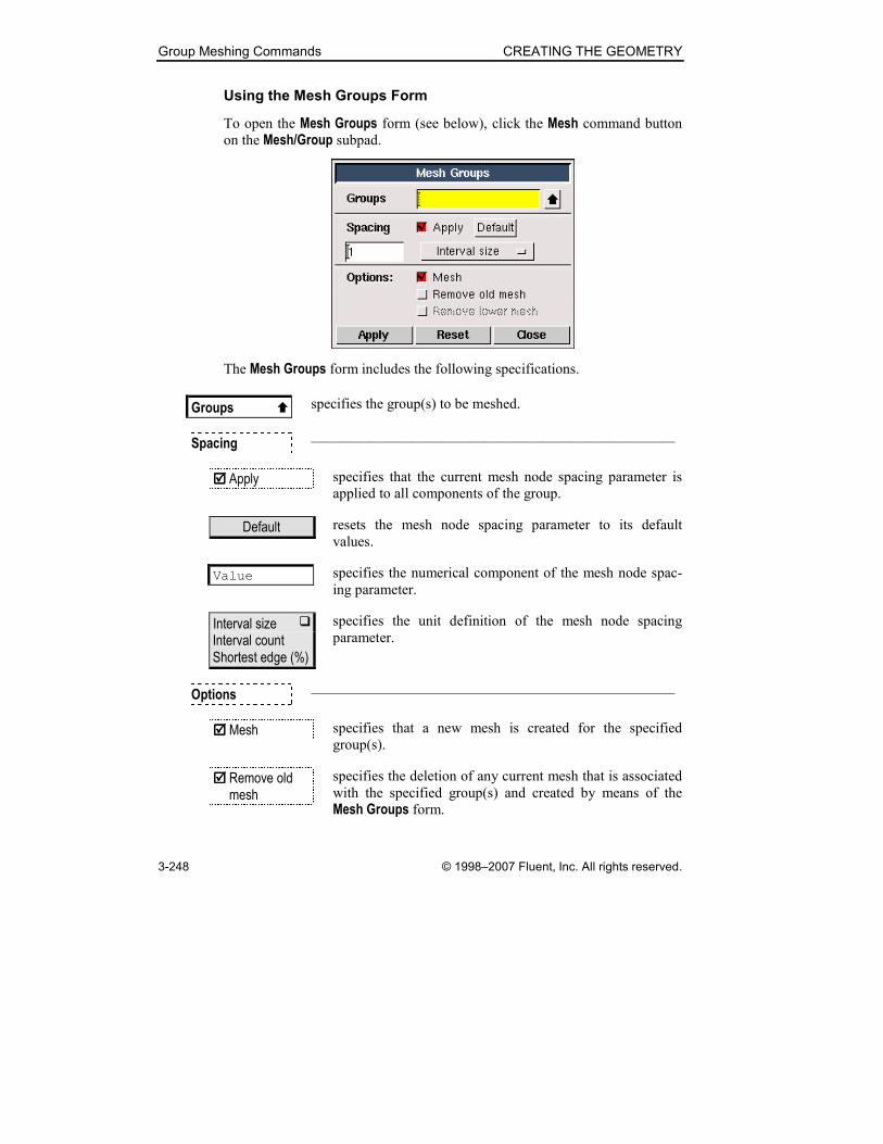
Group Meshing Commands CREATING THE GEOMETRY
3-248 © 1998–2007 Fluent, Inc. All rights reserved.
Using the Mesh Groups Form
To open the Mesh Groups form (see below), click the Mesh command button
on the Mesh/Group subpad.
The Mesh Groups form includes the following specifications.
Groups � specifies the group(s) to be meshed.
Spacing —————————————————————————
���� Apply specifies that the current mesh node spacing parameter is
applied to all components of the group.
Default resets the mesh node spacing parameter to its default
values.
Value specifies the numerical component of the mesh node spac-
ing parameter.
Interval size � Interval count Shortest edge (%)
specifies the unit definition of the mesh node spacing
parameter.
Options —————————————————————————
���� Mesh specifies that a new mesh is created for the specified
group(s).
���� Remove old mesh
specifies the deletion of any current mesh that is associated
with the specified group(s) and created by means of the
Mesh Groups form.

CREATING THE GEOMETRY Group Meshing Commands
© 1998–2007 Fluent, Inc. All rights reserved. 3-249
���� Remove lower mesh
specifies that all lower-topology (volume, face, and edge)
meshes associated with the specified group(s) are deleted.

Group Meshing Commands CREATING THE GEOMETRY
3-250 © 1998–2007 Fluent, Inc. All rights reserved.
3.5.2 Summarize/Check Group Meshes
The Summarize/Check Group Meshes command button lets you to perform the
following operations.
Symbol Command Description
Summarize Group Meshes Summarizes general group mesh
information in the Transcript window
Check Group Meshes Displays mesh quality information in
the Transcript window
The following sections describe the procedures and specifications required to
execute the operations listed above.
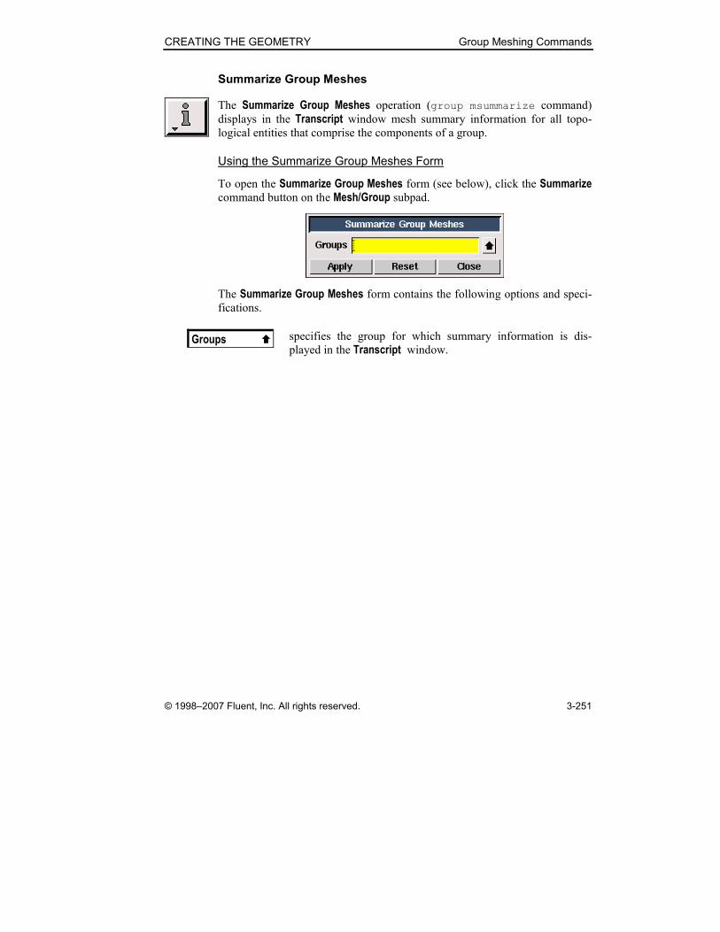
CREATING THE GEOMETRY Group Meshing Commands
© 1998–2007 Fluent, Inc. All rights reserved. 3-251
Summarize Group Meshes
The Summarize Group Meshes operation (group msummarize command)
displays in the Transcript window mesh summary information for all topo-
logical entities that comprise the components of a group.
Using the Summarize Group Meshes Form
To open the Summarize Group Meshes form (see below), click the Summarize command button on the Mesh/Group subpad.
The Summarize Group Meshes form contains the following options and speci-
fications.
Groups � specifies the group for which summary information is dis-
played in the Transcript window.
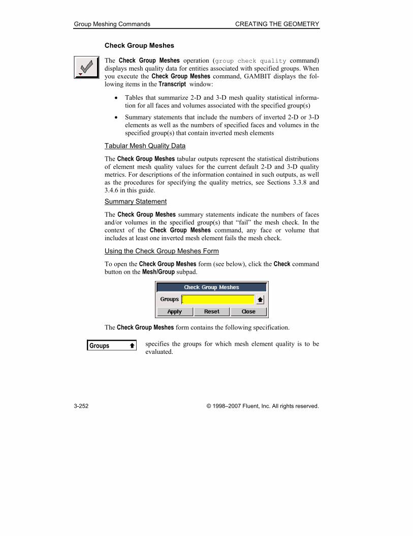
Group Meshing Commands CREATING THE GEOMETRY
3-252 © 1998–2007 Fluent, Inc. All rights reserved.
Check Group Meshes
The Check Group Meshes operation (group check quality command)
displays mesh quality data for entities associated with specified groups. When
you execute the Check Group Meshes command, GAMBIT displays the fol-
lowing items in the Transcript window:
• Tables that summarize 2-D and 3-D mesh quality statistical informa-
tion for all faces and volumes associated with the specified group(s)
• Summary statements that include the numbers of inverted 2-D or 3-D
elements as well as the numbers of specified faces and volumes in the
specified group(s) that contain inverted mesh elements
Tabular Mesh Quality Data
The Check Group Meshes tabular outputs represent the statistical distributions of element mesh quality values for the current default 2-D and 3-D quality
metrics. For descriptions of the information contained in such outputs, as well
as the procedures for specifying the quality metrics, see Sections 3.3.8 and
3.4.6 in this guide.
Summary Statement
The Check Group Meshes summary statements indicate the numbers of faces
and/or volumes in the specified group(s) that “fail” the mesh check. In the
context of the Check Group Meshes command, any face or volume that
includes at least one inverted mesh element fails the mesh check.
Using the Check Group Meshes Form
To open the Check Group Meshes form (see below), click the Check command
button on the Mesh/Group subpad.
The Check Group Meshes form contains the following specification.
Groups � specifies the groups for which mesh element quality is to be
evaluated.

CREATING THE GEOMETRY Group Meshing Commands
© 1998–2007 Fluent, Inc. All rights reserved. 3-253
3.5.3 Delete Group Meshes
The Delete Group Meshes operation (group delete onlymesh command)
removes the mesh from all topological entities that comprise components of
one or more groups.
When you delete the mesh for one or more groups, GAMBIT allows you to
delete all meshes that are associated with the lower-topology of the group
components. To delete the mesh associated with such components, select the
Remove lower unused mesh option on the Delete Group Meshes form.
As an example of the effect of the Remove lower unused mesh option, con-sider a group (group.1) that contains only a single volume (volume.1) and a single, separate face (face.7).
• If you delete the mesh from group.1 and select the Remove lower unused mesh option, GAMBIT deletes all vertex, edge, face, and vol-
ume meshes associated with volume.1 and face.7.
• If you delete the mesh from group.1 and do not select the Remove lower unused mesh option, GAMBIT deletes the volume mesh from volume.1 but retains all vertex, edge, and face meshes associated with volume.1. Likewise, GAMBIT deletes the face mesh from face.7 entity but retains all vertex and edge meshes associated with face.7.
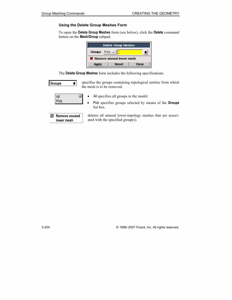
Group Meshing Commands CREATING THE GEOMETRY
3-254 © 1998–2007 Fluent, Inc. All rights reserved.
Using the Delete Group Meshes Form
To open the Delete Group Meshes form (see below), click the Delete command
button on the Mesh/Group subpad.
The Delete Group Meshes form includes the following specifications.
Groups � specifies the groups containing topological entities from which
the mesh is to be removed.
All � Pick
• All specifies all groups in the model.
• Pick specifies groups selected by means of the Groups list box.
���� Remove unused lower mesh
deletes all unused lower-topology meshes that are associ-
ated with the specified group(s).