3 - networking fundamentals, cabling & topology
DESCRIPTION
Networking Fundamentals, Cabling & TopologyTRANSCRIPT
Project 802
In 1985 The Institute of Electrical and Electronics Engineers’ (IEEE) started a Project 802 and their work on standards for local area and metropolitan area networks (LANs/MANs).
The committee met in February 1980, so they used the “80” from 1980 and the “2” from the second month to create the name Project 802.
The designation for an 802 standard always includes a dot (.) followed by either a single or a double digit. These numeric digits specify particular categories within the 802 standard. Currently, there are 12 standards.
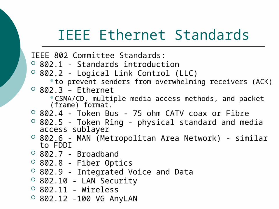
IEEE Ethernet StandardsIEEE 802 Committee Standards: 802.1 - Standards introduction 802.2 - Logical Link Control (LLC)
to prevent senders from overwhelming receivers (ACK) 802.3 – Ethernet
CSMA/CD, multiple media access methods, and packet (frame) format.
802.4 - Token Bus - 75 ohm CATV coax or Fibre 802.5 - Token Ring - physical standard and media access
sublayer 802.6 - MAN (Metropolitan Area Network) - similar to FDDI 802.7 - Broadband 802.8 - Fiber Optics 802.9 - Integrated Voice and Data 802.10 - LAN Security 802.11 - Wireless 802.12 -100 VG AnyLAN
IEEE 802.2
The 802.2 Logical Link Control This standard specifies the operation of the
Logical Link Control (LLC) sublayer of the Data Link layer of the OSI model.
The LLC sub layer provides an interface between the MAC sublayer and the Network layer.
The 802.2 standard is used by the IEEE 802.3 Ethernet specification (discussed next), but not by the earlier Ethernet 2 specifications (used in early implementations of Ethernet).
IEEE 802.3
The 802.3 CSMA/CD This standard was developed to match
the Digital, Intel, and Xerox (DIX) Ethernet networking technology.
The 802.3 standard, which resembles the DIX Ethernet, that people just started calling it Ethernet.
It is the most widely implemented of all the 802 standards because of its simplicity and low cost.
IEEE 802.8
The 802.8 Fiber-Optic LANs and MANs 802.8 is the report of a TAG on fiber optic
networks. The document discusses the use of optical fiber in networks
provides recommendations concerning the installation of fiberoptic cable,which includes Fiber Distributed Data Interface (FDDI) as well as 10BaseFL.
10BaseFL defines Ethernet over fiber-optic cable.

IEEE 802.11 The 802.11 Wireless LAN
802.11 is the name for a working group addressing wireless networking standards.
Wireless networking usually requires a higher up-front investment than cable-based networking.
Recently, 802.11 was updated to include the 802.11b standard, which specifies higher wireless speeds (11Mbps instead of 1Mbps for the original 802.11 standard). This demonstrates that the 802 standards have not been static for 20 years; instead, they’ve been a dynamic set of rules that continue to be updated as technology moves forward.
Ethernet at Data Link Layer The IEEE Divides the layer 2 of OSI into two sub
layer Logical Link Control Layer (LLC) Media Access Control Layer (MAC)
Data Link Layer Name IEEE Standard Description
Top part Logical Link Control (LLC) 802.2 Defines how to multiplex multiple network layer
protocols in the data link layer frame. Bottom part
Media Access Control (MAC) 802.3 Defines how information is transmitted in an
Ethernet environment, and defines the framing, MAC addressing.
Framing Framing is the Layer 2 encapsulation process.
Bit streams (data) 010101 alone can not be sent between devices.
We must divide the data up and add:
a bit pattern to flag the start of each framerelevant MAC addressesa block of datasome bits for error detectiona bit pattern to flag the end of the frame
A frame is the Layer 2 protocol data unit (PDU).
Layer 2 Framing
LLC
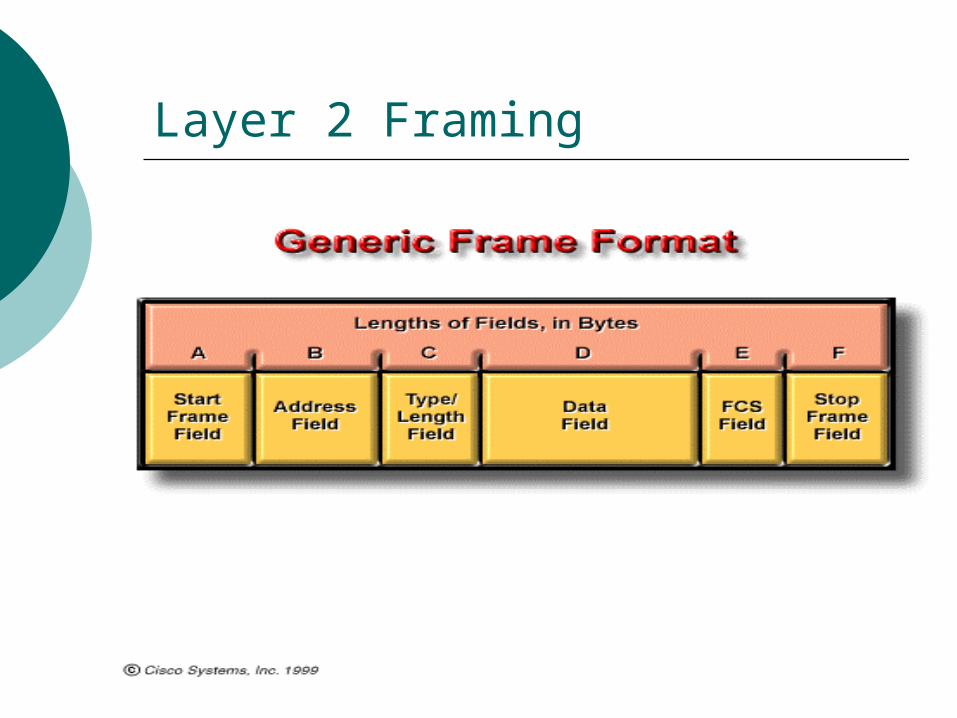
IEEE 802.3 is responsible for defining the framing used to transmit information between two NICs.
A frame standardizes the fields in the frame and their lengths so that every device understands how to read the contents of the frame
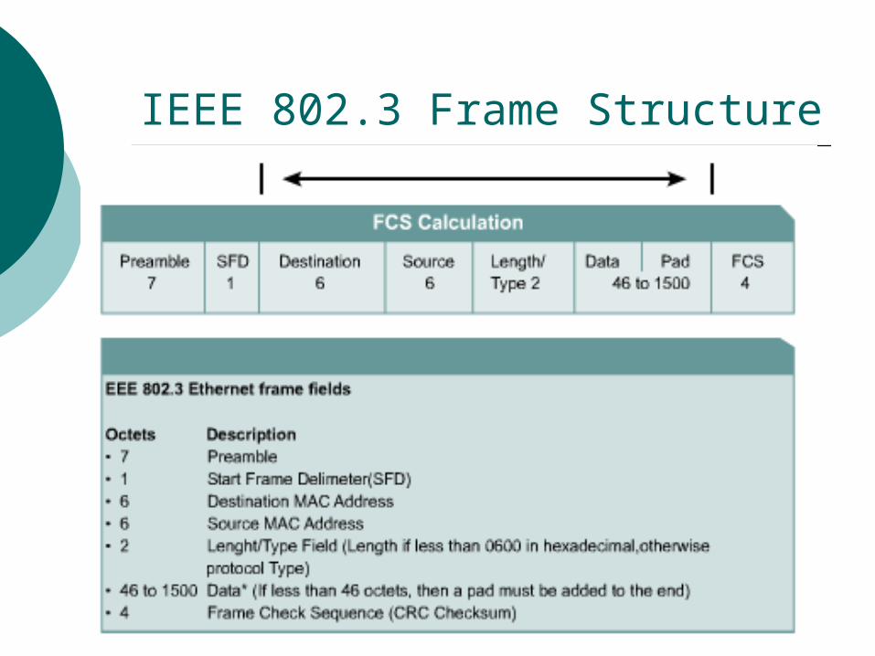
IEEE 802.3 Frame Structure
Ethernet at Physical Layer
IEEE define Two categories
Baseband The word base specify digital signal.
Broadband The word broad specify analogue
signal.

Types of Ethernet
1980s---The 10-Mbps Ethernet standard remained virtually unchanged until 1995 when IEEE announced a standard for a 100 Mbps Fast Ethernet
The standards for Gigabit Ethernet emerged in only three years.
An even faster Ethernet version, 10 Gigabit Ethernet, is now widely available and still faster versions are being developed
10BASE5, 10BASE2, and 10BASE-T Ethernet are now considered Legacy Ethernet
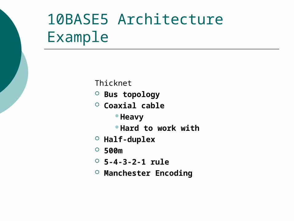
10BASE5 Architecture Example
Thicknet Bus topology Coaxial cable
HeavyHard to work with
Half-duplex 500m 5-4-3-2-1 rule Manchester Encoding
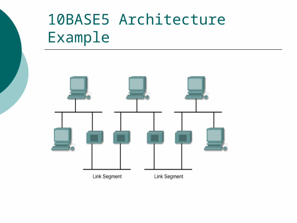
10BASE5 Architecture Example

10BASE2 Network Design Limits
Thinnet Bus topology Coaxial cable
LighterEasier to work with
BNC connectors Half-duplex 185m 5-4-3-2-1 rule Manchester
Encoding
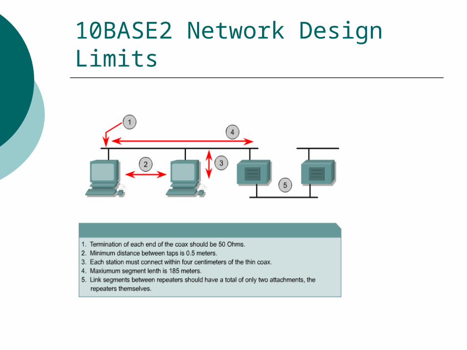
10BASE2 Network Design Limits

10BASE-T Repeated Network Design Limits
Star Topology UTP cable
LighterEasier to work withCheaper
RJ-45 connectors Half-duplex or full-duplex 100m(90 + 10) Manchester Encoding Linked hubs add to distance
and delay

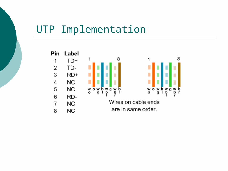
10BASE-T Modular Jack Pinouts
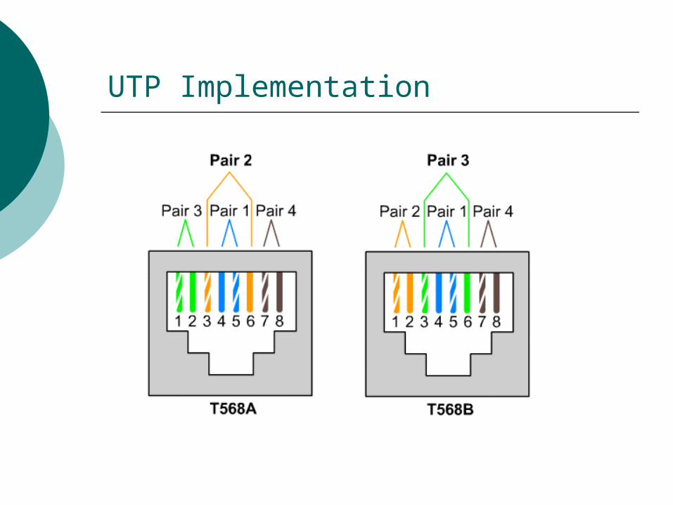
UTP Implementation

UTP Implementation
10BASE- F Network Design Limits
Star Topology Fibre Optic cable
Lighter Easier to work with SC connectors
Half-duplex or full-duplex 2 K.M. Manchester Encoding Linked hubs add to distance and
delay
5-4-3 Repeater Rule
10-Mbps Ethernet operates within the timing limits offered by a series of not more than five segments separated by no more than four repeaters. This is known as the 5-4-3 rule.
No more than four repeaters may be connected in series between any two distant stations. There can also be no more than three populated segments between any two distant stations
NOTE: This only applies to the old 10Mbps coax and does NOT apply to twisted pair

Ethernet At Physical Layer
Cable Name Cable Type Transmission Rate
Max. length before repeater needed
Max. No. ofComputer
10Base5 Thick coaxial
10Mbsec 500 metres 100 per segment
10Base2 Thin coaxial cable
10Mbsec 200 metres 30 per segment
10BaseT Twisted Pair 10/100 Mbsec
100 metres 1024 per segment
10BaseF Fiber Optic cable
100/1000 Mbsec
2000 metres 1024 per segment
Fast Ethernet To send Data at a rate of 10 MBPS take 57.6
micro second. Before last frame send 1st must be reached & if
there is collision it must be resend. That is collision must be detected during 57.6
micro second. This time is sufficient to make a round- trip
time. To increase data rate without decreasing frame
size we decrease round-trip time.

Fast Ethernet As we increase speed 10 times from 10
MBPS to 100 MBPS round –trip time should be decrease by 10 i.e. time reduce to 5.76 micro second.
Collision domain also decrease 10 times from 2500 meter to 250 meter.
So the Fast Ethernet is a Version of Ethernet with 100 MBPS data rate, with no change in frame size, no change in access method, only decrease in collision domain.
Parameters for 100-Mbps Ethernet Operation
100-Mbps Ethernet is also known as Fast Ethernet.
Operates in full duplex and half duplex mode
The two technologies that have become important are 100BASE-TX, which is a copper UTP medium 100BASE-FX, which is a multimode optical
fiber medium 0
Types of Ethernet
100 Base TX Uses two pair of twisted pair, one pair for
transmission and one pair for reception. Uses either STP or Cat 5 UTP.
Transmission Rate100 Mb/s (200 Mb/s in optional full-duplex mode)
Cable Type 100-ohm impedance rating, Connecter TechnologyRJ-45 style modular
jack (8-pins) for UTP cabling.
Types of Ethernet
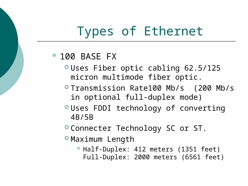
100 BASE FX Uses Fiber optic cabling 62.5/125 micron
multimode fiber optic. Transmission Rate100 Mb/s (200 Mb/s in
optional full-duplex mode) Uses FDDI technology of converting 4B/5B Connecter Technology SC or ST. Maximum Length
Half-Duplex: 412 meters (1351 feet)Full-Duplex: 2000 meters (6561 feet)

1000-Mbps Ethernet ---Gigabit The 1000-Mbps Ethernet or Gigabit Ethernet
standards IEEE 802.3z represent transmission using both fibre and copper media.
The 1000BASE-LXand SX standard, IEEE 802.3ab, specifies 1 Gbps full duplex over optical fiber.
The 1000BASE-X standard, IEEE 802.3ab, specifies 1 Gbps full duplex over twisted pair cable.
The strategy is same MAC layer & the encoding system change, as it is mainly design for Fibre optic Cable.
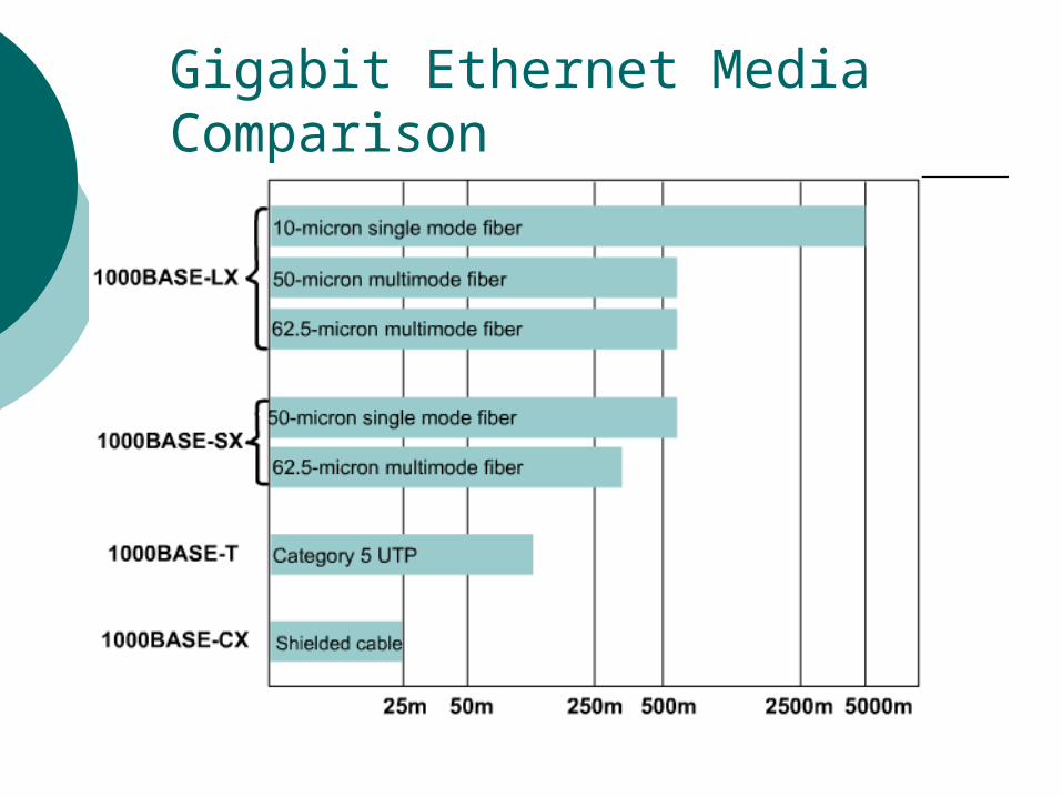
Gigabit Ethernet Media Comparison
The 10GB Ethernet 10-Gbps Ethernet (IEEE 802.3ae) was standardized
in June 2002.
It is a full-duplex protocol that uses only optic fiber as a transmission medium.
The maximum transmission distances depend on the type of fiber being used.
When using single-mode fiber as the transmission medium, the maximum transmission distance is 40 kilometers (25 miles).
Twisted Pair Cabling
Twisted pair cables are so named because pairs of wires are twisted around one another. Each pair consists of two insulated copper wires twisted together. The wire pairs are twisted because it helps reduce crosstalk and noise susceptibility. High quality twisted pair cables have about 1 to 3 twists per inch. For best results, the twist rate should vary significantly between pairs in a cable.
Twisted pair cables are used with the following Ethernet physical layers: 10Base-T, 100Base-TX, 100Base-T2, 100Base-T4, and 1000Base-T. The following sections describe the various types of twisted pair cabling.

Unshielded Twisted Pair Cabling (UTP)
“Unshielded Twisted Pair" (UTP) cabling is twisted pair cabling that contains no shielding. For networking applications, the term UTP generally refers to the 100 ohm.
Category 3, 4, & 5 cables specified in the TIA/EIA 568-A standard. Category 5e, 6, & 7 standards have also been proposed to support higher speed transmission.
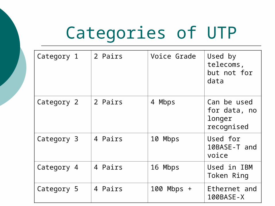
Categories of UTPCategory 1 2 Pairs Voice Grade Used by
telecoms, but not for data
Category 2 2 Pairs 4 Mbps Can be used for data, no longer recognised
Category 3 4 Pairs 10 Mbps Used for 10BASE-T and voice
Category 4 4 Pairs 16 Mbps Used in IBM Token Ring
Category 5 4 Pairs 100 Mbps + Ethernet and 100BASE-X
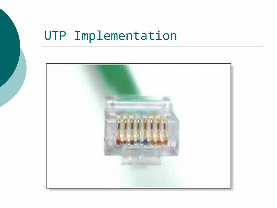
UTP Implementation
UTP Implementation
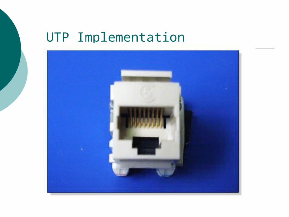
UTP Implementation

UTP Implementation
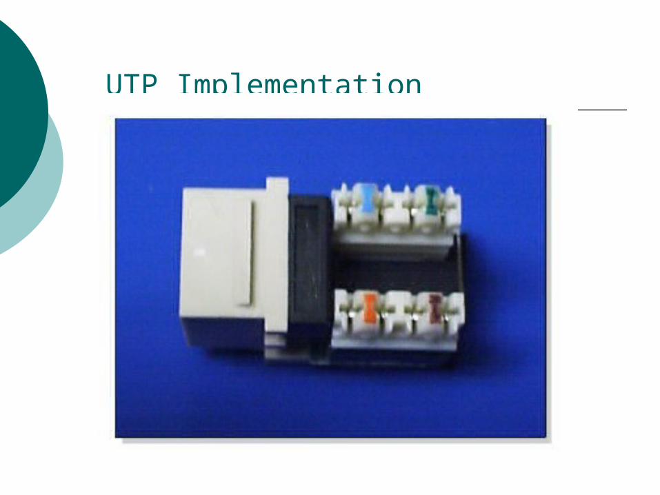
UTP Implementation

Straight-Through Cable
The straight-through cable is used to connect: Host to switch or hub Router to switch or hub
Four wires are used in straight-through cable to connect Ethernet devices. It is relatively simple.

Straight-Through Cable
Crossover Cable
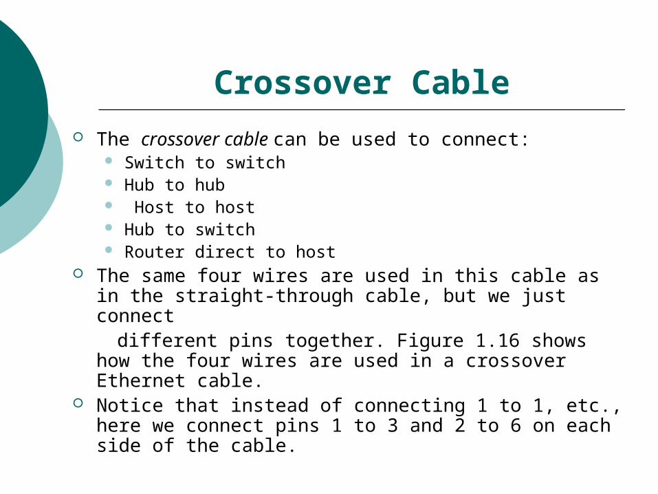
The crossover cable can be used to connect: Switch to switch Hub to hub Host to host Hub to switch Router direct to host
The same four wires are used in this cable as in the straight-through cable, but we just connect
different pins together. Figure 1.16 shows how the four wires are used in a crossover Ethernet cable.
Notice that instead of connecting 1 to 1, etc., here we connect pins 1 to 3 and 2 to 6 on each side of the cable.

Crossover Cable

Networking Topology
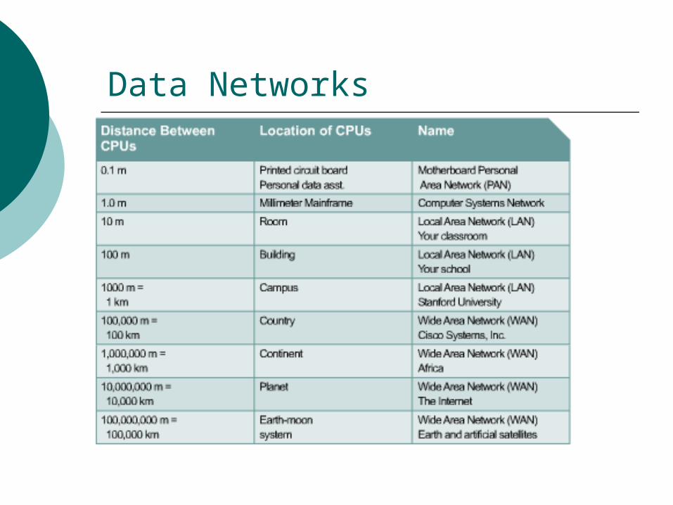
Data Networks

Networking Devices

Functions of Various Devices
A repeater is a network device used to regenerate a signal.
Hubs concentrate connections. Bridges convert network transmission data
formats as well as perform basic data transmission management.
Workgroup switches add more intelligence to data transfer management.
Routers - They can also connect to a WAN, which allows them to connect LANs that are separated by great distances.
Network Topology
Network topology
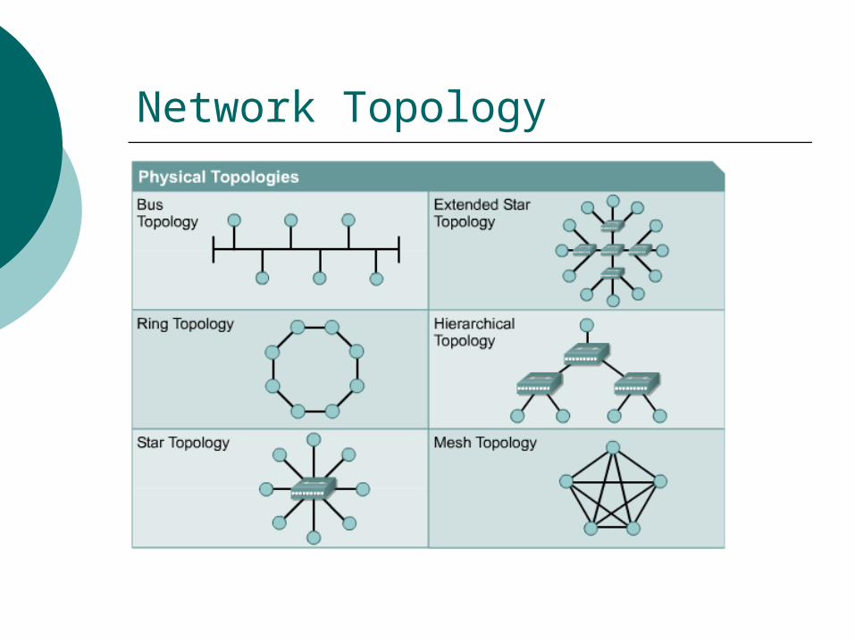
A bus topology uses a single backbone cable that is terminated at both ends. All the hosts connect directly to this backbone.
A ring topology connects one host to the next and the last host to the first. This creates a physical ring of cable.
A star topology connects all cables to a central point of concentration.
An extended star topology links individual stars together by connecting the hubs and/or switches.

Network topology
A hierarchical topology - instead of linking the hubs and/or switches together, the system is linked to a computer that controls the traffic on the topology.
A mesh topology is implemented to provide as much protection as possible from interruption of service.
LANs
LANs consist of the following components: Computers Network interface cards Peripheral devices Networking media Network devices
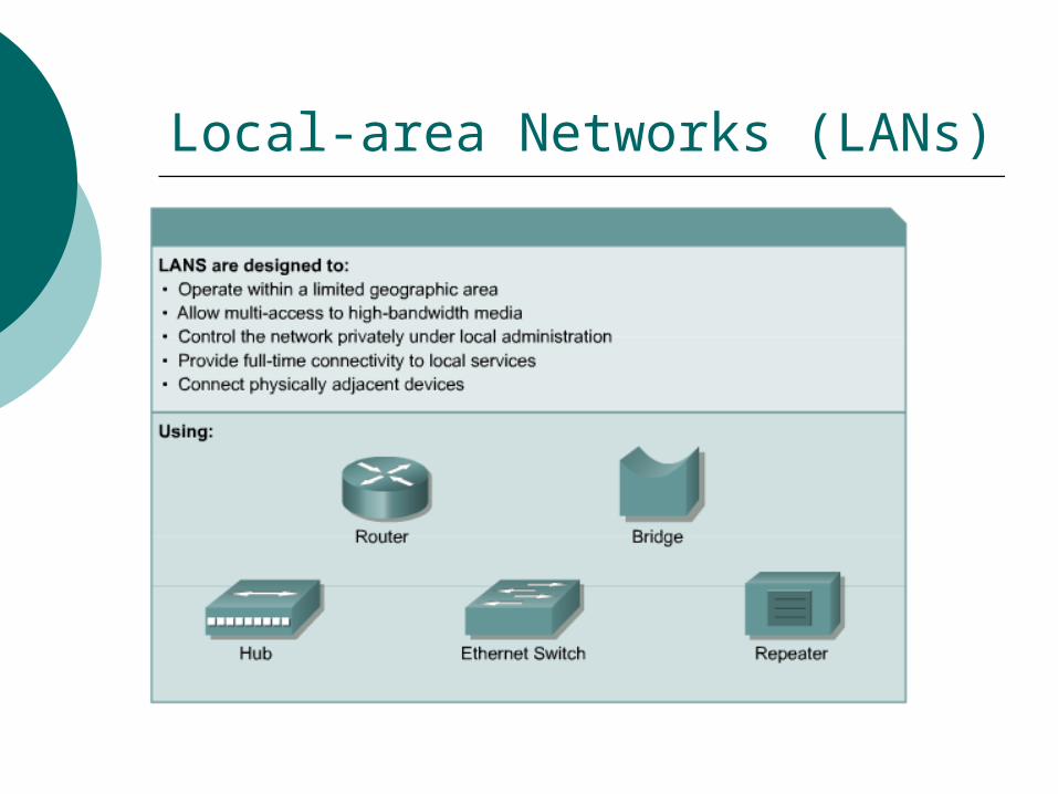
Local-area Networks (LANs)
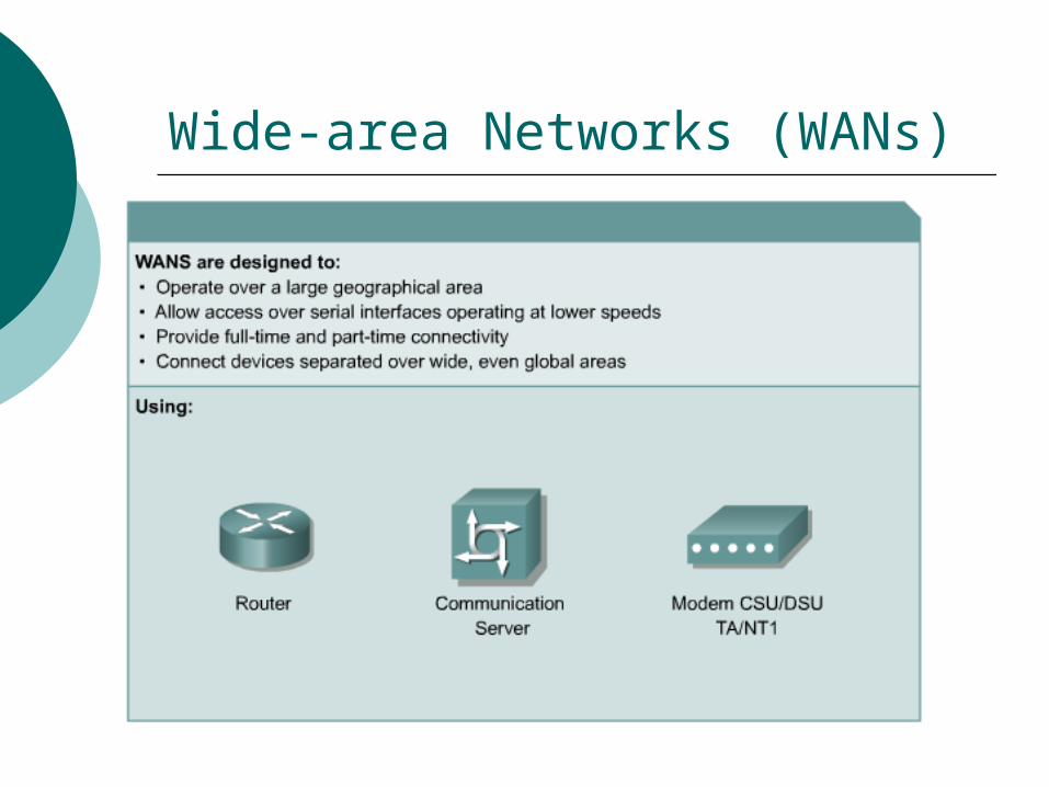
Wide-area Networks (WANs)

WANs
Some common WAN technologies are: Modems Integrated Services Digital Network
(ISDN) Digital Subscriber Line (DSL) Frame Relay US (T) and Europe (E) Carrier Series – T1,
E1, T3, E3 Synchronous Optical Network (SONET)

Metropolitan-Area Network (MANs)

Storage-Area Networks (SANS)
SANs
A SAN is a dedicated, high-performance network used to move data between servers and storage resources.
Because it is a separate, dedicated network, it avoids any traffic conflict between clients and servers
Features of SAN
Performance – SANs enable concurrent access of disk or tape arrays by two or more servers at high speeds, providing enhanced system performance.
Availability – SANs have disaster tolerance built in, because data can be mirrored using a SAN up to 10 kilometers (km) or 6.2 miles away.
Options – Allows easy relocation of backup data, operations, file migration, and data replication between systems.

Bandwidth & Baud Rate
The amount of data that can be carried from one point to another in a given time period (usually a second). This is expressed in bits/second ( bps ).
The baud rate is the number of times per second a serial communication signal changes states; a state being either a voltage level, a frequency, or a frequency phase angle.
If the signal changes once for each data bit, then one bps is equal to one baud. For example, a 300 baud modem changes its states 300 times a second.
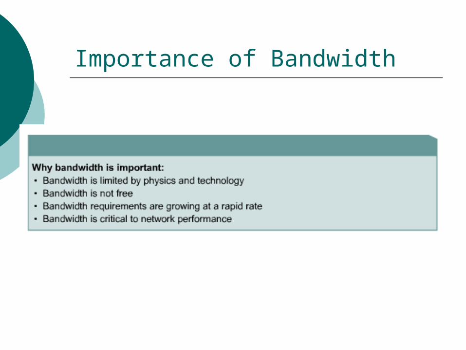
Importance of Bandwidth

Bandwidth Limitations
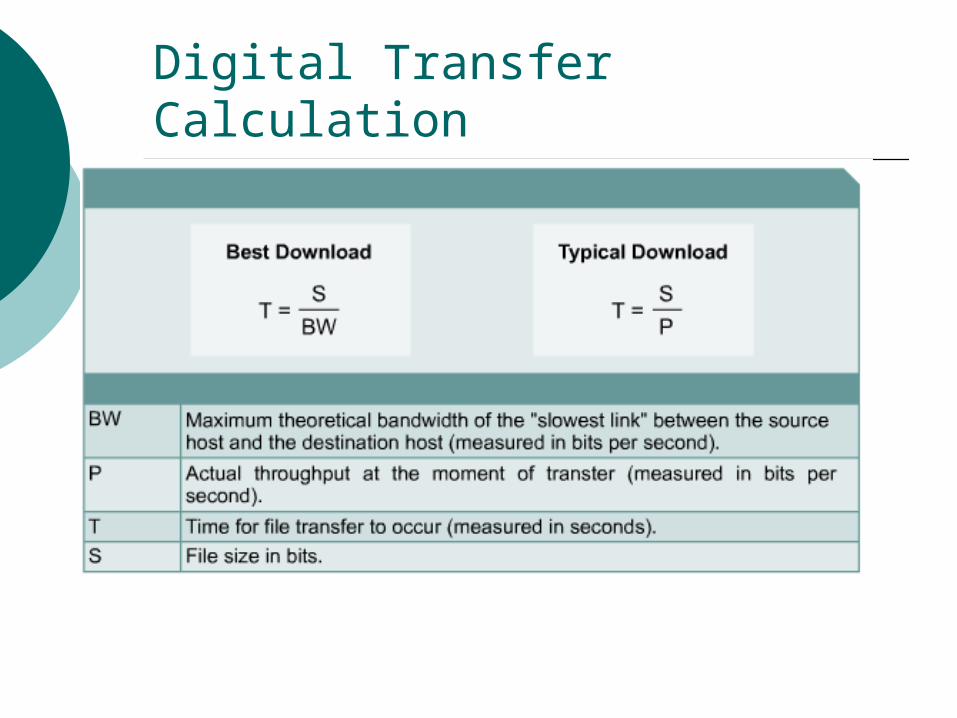
Digital Transfer Calculation