structured cabling and network topology: the present … · structured cabling and network...
TRANSCRIPT

Structured Cabling and Network Topology: The
Present and the Future
Allan Ridley (M. Eng)
20 August, 2015

What does the Data Centre represent?
Business
Results
Productivity Image
Expense
Revenue
Security

The terms we see today
Big Data
Analytics
Virtualisation Green
Cloud DCIM
SDNEthernet
FCoE
iSCSi
Infiniband
Fibre Channel
10G/40G/100G
Well-chosen Infrastructure must be in place to enable these

Infrastructure Standards: Data Centre
Copper
Fibre
Connectors
Cat 6 MinimumCat 6A
(Class EA)
Cat 6A
(Class EA)
OM3 / OS1
Minimum
OM3 / OS1
Minimum
OM3 / OS1
Minimum
LC
MPO
LC
MPO
LC
MPO
TIA/EIA-942 EN 50173-5 ISO 24764

Pre-Terminated Cabling in theData Center – Industry Trends
Pre-TerminatedCables/ Pigtails
68%10%
14%8%
OtherField Term/Polish
Pre-polishmech
Fibre
>75%
Copper
>30%
68%

• Typical pre-term copper install is eight times faster
than field term
• Reduces deployment risk
• “Phase II” install much less disruptive
• Minimal packaging on site – GREEN
• Stepping stone to 40/100G
Installation time dramatically reduced
Scalability and ease of installationpre-terminated cabling
ScalabilityScalabilityScalability

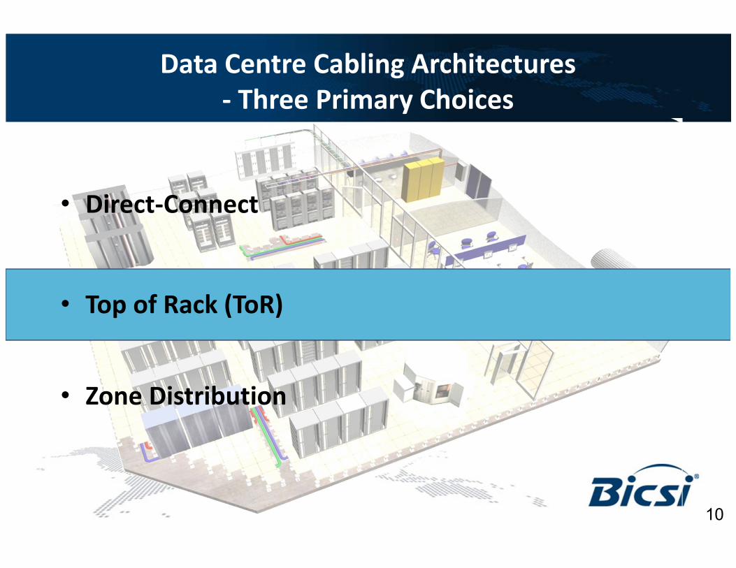
Data Centre Cabling Architectures
- Three Primary Choices
• Direct-Connect
• Top of Rack (ToR)
• Zone Distribution
7

Direct Connect Architecture
PRO:
• Optimised for smaller
Data Centres
• Requires less
networking
equipment than
distributed cabling
architecture,
• Avoids network
bottlenecks due to
switch
oversubscription in
distribution areas
• Direct connect
provides optimal port
utilization
Fibre cabling
Copper cablingPrimary Entrance Room (Carrier
and Demarcation)

Direct Connect Architecture
CON:
• Not optimised for
large/mega data
centres
• Cable bulk increases
with new cable runs
and airflow is often
negatively affected
Fibre cabling
Copper cablingPrimary Entrance Room (Carrier
and Demarcation)
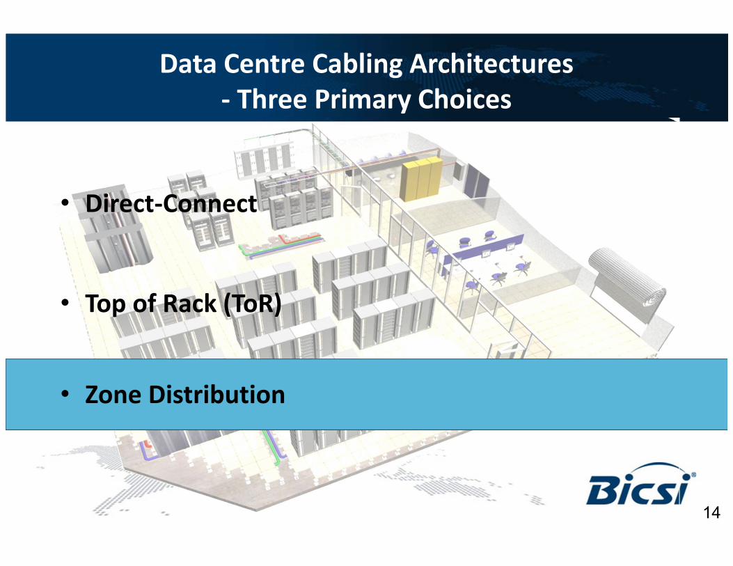
Data Centre Cabling Architectures
- Three Primary Choices
• Direct-Connect
• Top of Rack (ToR)
• Zone Distribution
10
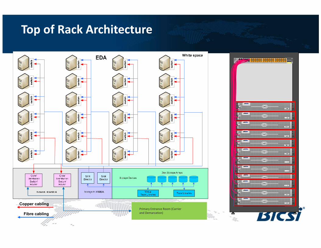
Top of Rack Architecture
Fibre cabling
Copper cablingPrimary Entrance Room (Carrier
and Demarcation)

Top of Rack Architecture
PRO:
• Efficient use of cables
• Good scalability
• Easy cable management
• Efficient use of floor space
Fibre cabling
Copper cablingPrimary Entrance Room (Carrier
and Demarcation)

Top of Rack Architecture
CON:
• ToR switch for every server
cabinet
• Difficult server Move, Add or
Change process
• Increased network
management overhead
• Poor port utilization due to
power/cooling limits
• Primary / Secondary / SAN /
OOB must be considered.
Fibre cabling
Copper cablingPrimary Entrance Room (Carrier
and Demarcation)
Data Centre Cabling Architectures
- Three Primary Choices
• Direct-Connect
• Top of Rack (ToR)
• Zone Distribution
14
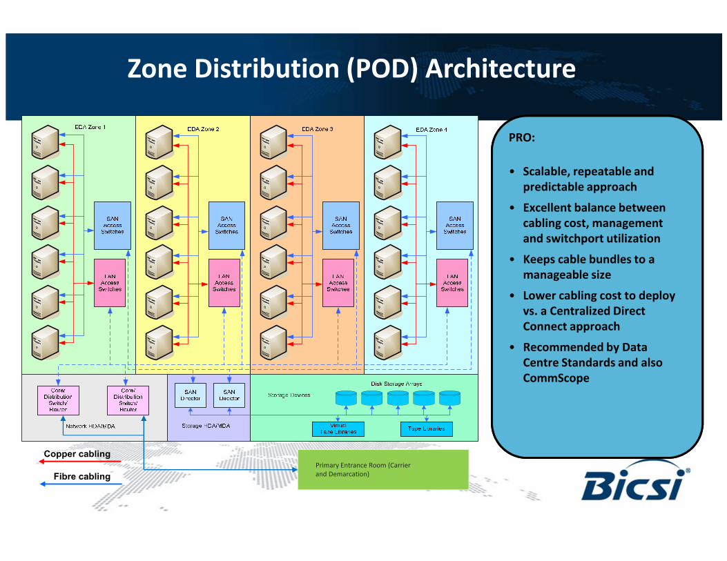
Zone Distribution (POD) Architecture
PRO:
• Scalable, repeatable and
predictable approach
• Excellent balance between
cabling cost, management
and switchport utilization
• Keeps cable bundles to a
manageable size
• Lower cabling cost to deploy
vs. a Centralized Direct
Connect approach
• Recommended by Data
Centre Standards and also
CommScope
Fibre cabling
Copper cablingPrimary Entrance Room (Carrier
and Demarcation)

Zone Distribution (POD) Architecture
CON:
• Not ideally suited to very
small DCs
• Not suitable for mainframe
data centre
• High intial CapEx on EoR /
MoR switches
Fibre cabling
Copper cablingPrimary Entrance Room (Carrier
and Demarcation)

Distribution
Switches
Aggregation Switches
Hosts
Current Data Center Networks:
Traditional 3-layer architecture
Core Switches/
Routers
Hosts Hosts Hosts
Shortcomings may be Bottlenecking / Latency

Leaf Switches
Spine
Switches
New Data Center Networks:
Leaf/Spine design
Core Router
HostsHosts Hosts Hosts
Shortcomings may be cost / management

Case Study
Implementing a
10/40/100Gbps
Leaf/Spine Data Centre

Standards Based Ethernet Transceivers
• QSFP – Quad Small Form Factor Pluggable – 8f
• 1x40G // (4)x10G
• 12f MPO – MPO Array Cord / 8f MPO – LC Array Cord
• SFP/SFP+ – Small Form Factor Pluggable – 2f
• 1x1G // 1x10G
• Duplex LC Patch Cord
• CXP – 24f
• 1x100G // (3) 40G // (12)x10G – 24f
• 24f MPO – MPO Array Cord / 24f MPO – LC Array Cord
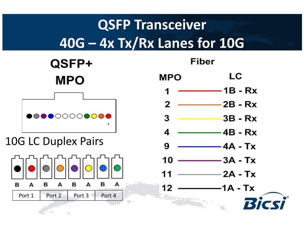
QSFP Transceiver
40G – 4x Tx/Rx Lanes for 10G
10G LC Duplex Pairs
Port 1 Port 2 Port 3 Port 4

CXP 24f MPO
Lane assignments

4 x 10G Array
Multiple 2-fiber
applications on 12f
cabling
MPO
12 active fibers
40G-SR4
breakout to
10G-SR
MPO
8 active fibers
120Gb/s
breakout to
10G-SR
MPO
24 active fibers
120Gb/s
breakout to
40G-SR4
MPO
24 active fibers
100G-SR10
on 12f cabling
MPO
20 active fibers
6
12f
48f
12
24f
8f24f
8f
8f
12f24f
12f
Array Connectivity =
Application Support Flexibility
Not used for IEEE
10/40/100G Migration6 duplex LC
4 x 10G4 duplex LC
12 x 10G12 duplex LC
3 x 40G3 x 8f MPO
1 x 100G2 x 12f MPO

IEEE 802.3ba: 40/100G Ethernet
Approved June 2010
10G 40G 100GApproach
Laser Type
Fiber Type
Connector
Transceiver
Tolerances
Maximum
Distance
# of Fibers
10G x4
VCSEL Array
OM3/OM4
MPO
Relaxed
(to lower cost)
OM3: 100+ m*
OM4: 125 – 150 m*
12
10G x10
VCSEL Array
OM3/OM4
MPO x 2
Relaxed
(to lower cost)
OM3: 100m*
OM4: 150 m
24
10G
VCSEL
OM3/OM4
LC x2
Tight
OM3: 300m
OM4: 550m
2
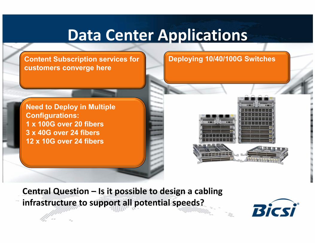
Data Center Applications
Central Question – Is it possible to design a cabling
infrastructure to support all potential speeds?
Content Subscription services for
customers converge here
Deploying 10/40/100G Switches
Need to Deploy in Multiple
Configurations:
1 x 100G over 20 fibers
3 x 40G over 24 fibers
12 x 10G over 24 fibers

Customer Requirements
Support
10/40/100G
Seamless
Migration to
100G
Common
Physical
Layer
Design
Built-in
Flexibility
Minimize
Complexity
and PartsImplement
Automated
Infrastructur
e
Management
(AIM)
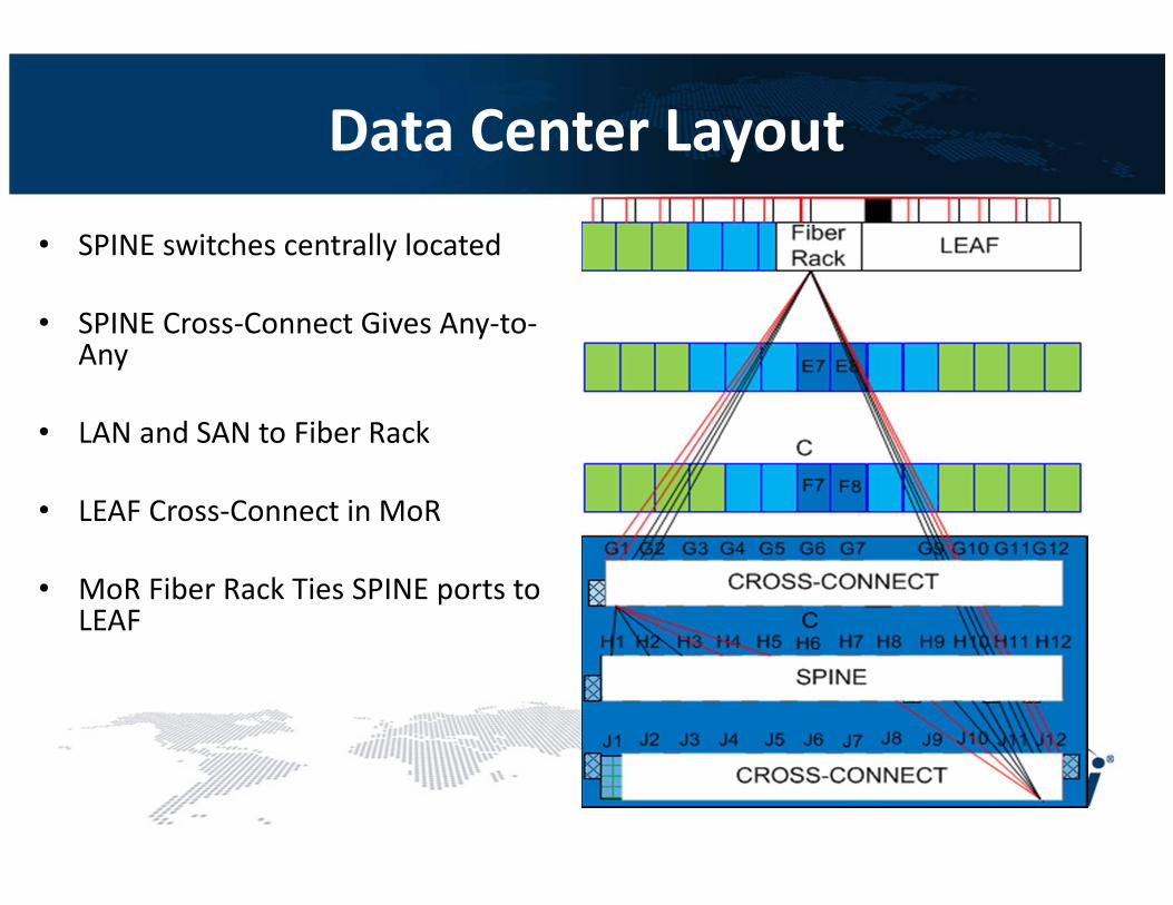
• SPINE switches centrally located
• SPINE Cross-Connect Gives Any-to-Any
• LAN and SAN to Fiber Rack
• LEAF Cross-Connect in MoR
• MoR Fiber Rack Ties SPINE ports to LEAF
Data Center Layout

• 11RU chassis with a 30Tbps fabric
• Supports up to 8 line cards and provides
• 1,152 – 10Gb ports,
• 288 – 40Gb ports, or
• 96 – 100Gb Ethernet ports in a single system
• Unparalleled density and performance in the
industry.
The Spine Switch 24f MXP
SPINE SWITCH
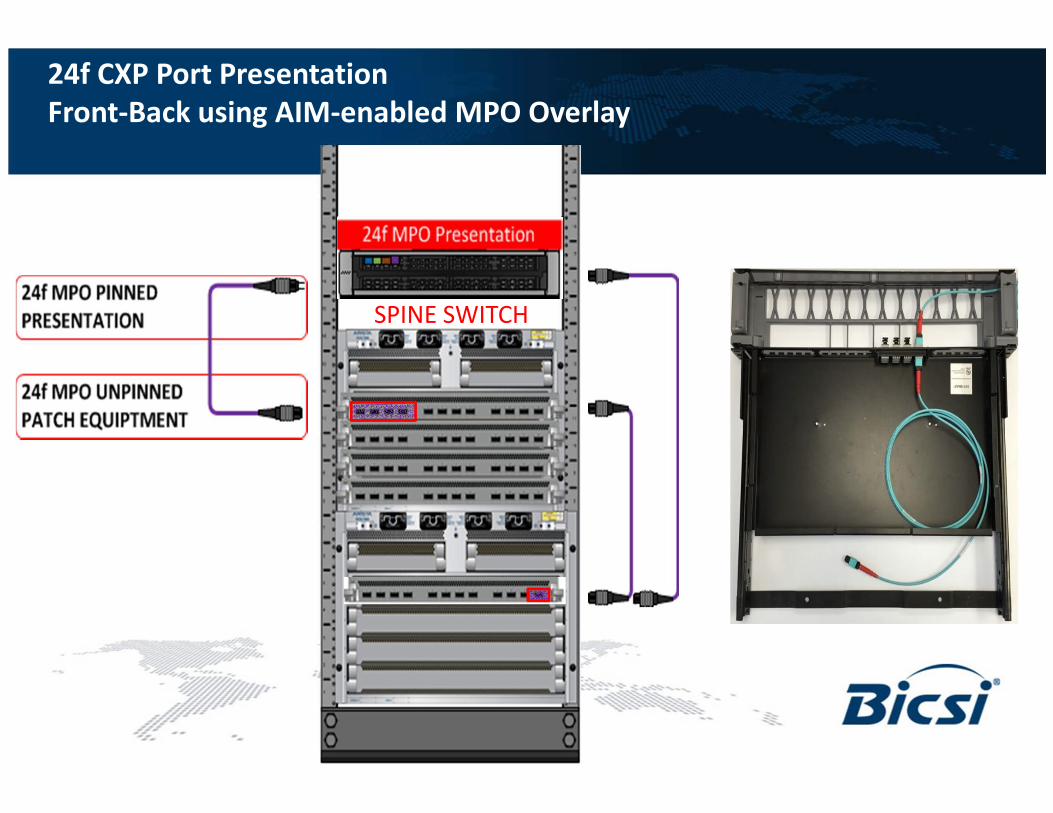
24f CXP Port Presentation
Front-Back using AIM-enabled MPO Overlay

SPINE SWITCH
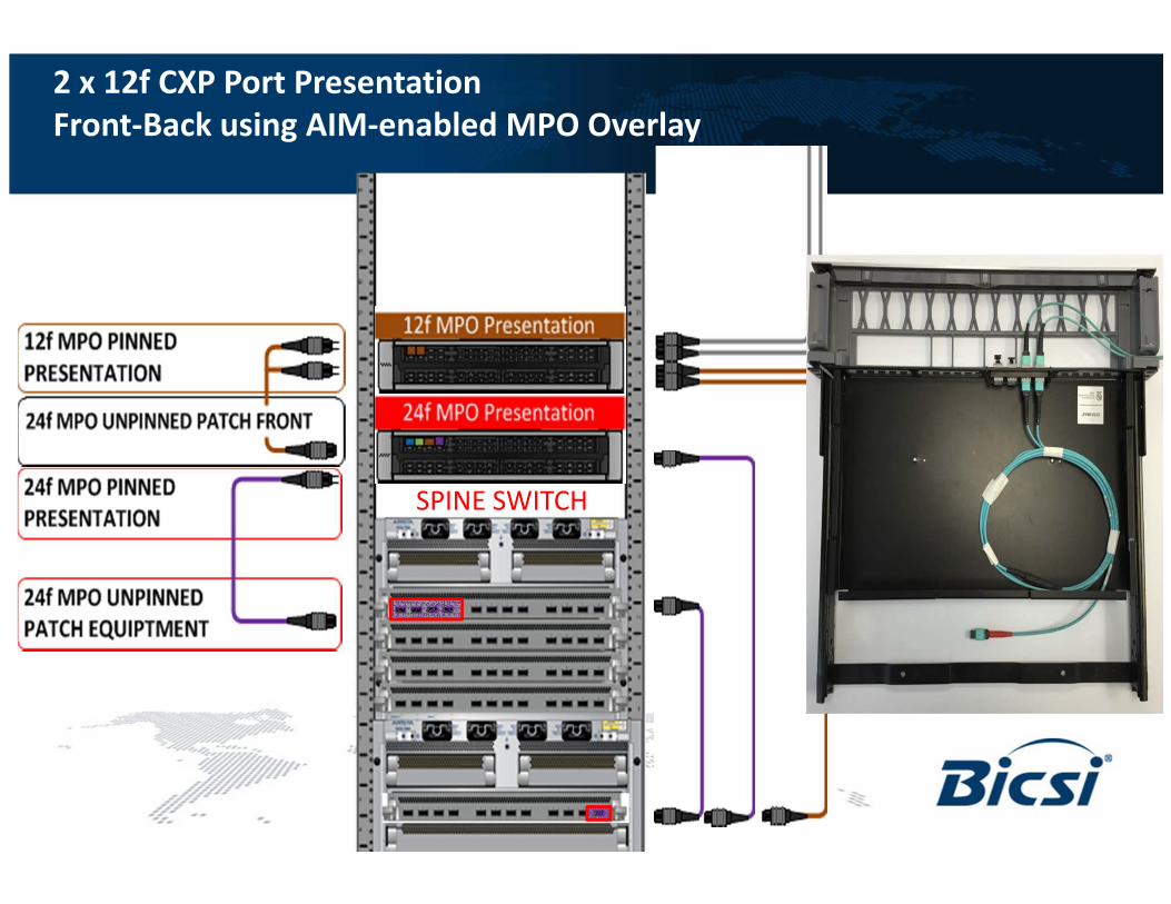
2 x 12f CXP Port Presentation
Front-Back using AIM-enabled MPO Overlay
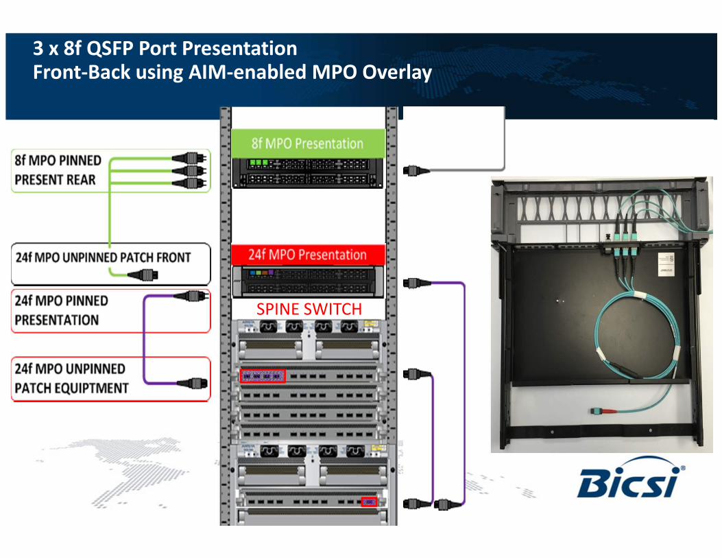
SPINE SWITCH
3 x 8f QSFP Port PresentationFront-Back using AIM-enabled MPO Overlay
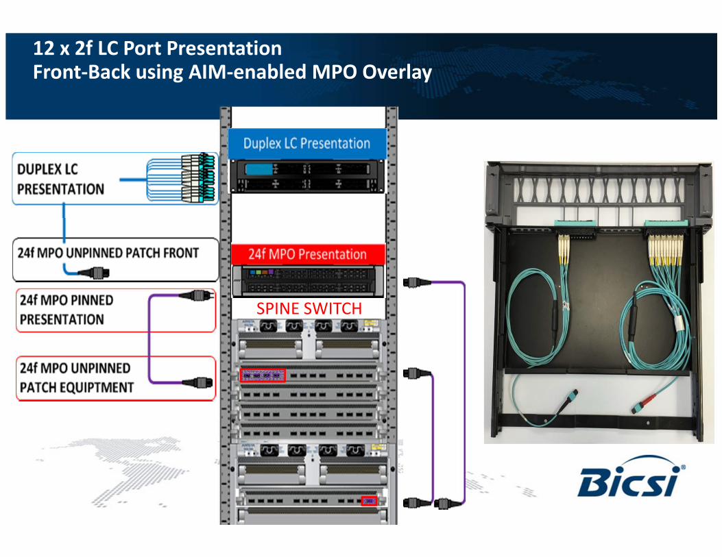
SPINE SWITCH
12 x 2f LC Port PresentationFront-Back using AIM-enabled MPO Overlay

Leaf Tie Panels to Spine Presentation Panels: Cross-Connect
TO PRESENTATION
PANELS

Leaf Tie Panels to Spine Presentation Panels: Full Connectivity
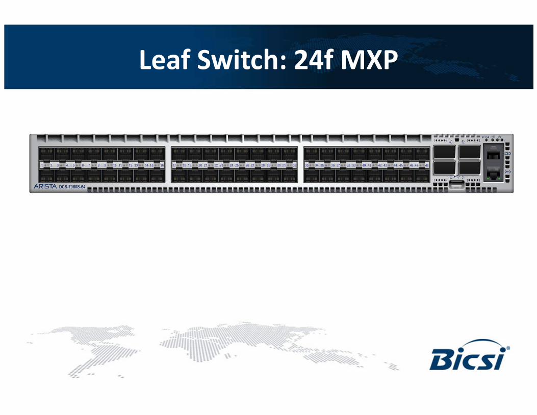
Leaf Switch: 24f MXP

RACK LEVEL LEAF // LEAF-
SERVER CABINET

MPO Array cords used for port extension
• 10,000 sqft
• 40 SPINE 4 Post Racks
• 192 LEAF Cabinets
24f Port extension cable
24f MPO (f) - 24f MPO(m), 9' length
MXP
PresentationSPINE
24f Bi-furcated port extension cable
24f MPO (f) - (2) 12f MPO(m), 5' length
100G
PresentationSPINE
24f Tri-furcated port extension cable
24f MPO (f) - (3) 8f MPO(m), 6' length
40G
PresentationSPINE
24f MPO-LC port extension cable
24f MPO (f) – (12) 2f LC, 7’ length
10G
PresentationSPINE
24f Tri-furcated port extension cable
24f MPO (f) - (3) 8f MPO(m), 15' length
40G
Presentation LEAF

Trace Diagrams 10/40/100
Front-Back
EquipmentFront-Back
Array
24
LC duplex cordsLC duplex cords MPO Trunk
Cable
SPINE
LEAF
Front-Back
Equipment
12f each
MPO Patch
cordsMPO Trunk
Cable
12f each
3x8f
24f12f each
24f equipment
cordMPO Patch
cords
Front-Back
Array
3x8f
24f
SPINE
Front-Back
Equipment
12f each
MPO Patch
cordsFront-Back
Array
Front-Back
Array
SPINE
2x12ff
24f
12f 12f
24f
12f
Front-Back
Equipment
LEAF
SPINE
24
12x2f
24
24f
24
24
10GbE Duplex LC Connectivity Trace
40GbE 8f MPO Connectivity Trace
100GbE 24f MPO Connectivity Trace
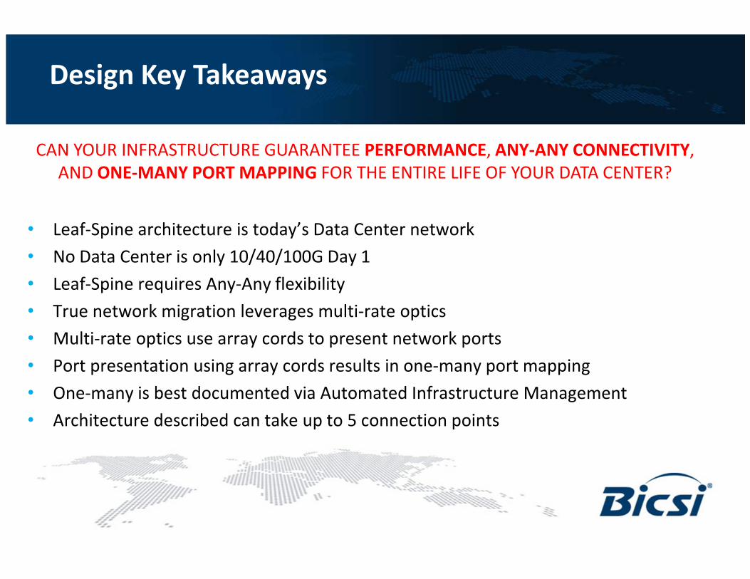
Design Key Takeaways
• Leaf-Spine architecture is today’s Data Center network
• No Data Center is only 10/40/100G Day 1
• Leaf-Spine requires Any-Any flexibility
• True network migration leverages multi-rate optics
• Multi-rate optics use array cords to present network ports
• Port presentation using array cords results in one-many port mapping
• One-many is best documented via Automated Infrastructure Management
• Architecture described can take up to 5 connection points
CAN YOUR INFRASTRUCTURE GUARANTEE PERFORMANCE, ANY-ANY CONNECTIVITY,
AND ONE-MANY PORT MAPPING FOR THE ENTIRE LIFE OF YOUR DATA CENTER?

Thank You