300 petty drive suite e lawrenceville, ga 30043ceteccorp.com/pdf/32004 - dcp manual.pdf300 petty...
TRANSCRIPT

300 Petty Drive
Suite E Lawrenceville, GA 30043
770-817-7810
Sliding Mass Dynamic Cone Penetrometer
(DCP) PART#32004
CetecCorp.com

1
NOTICE
This Instruction Manual is an integral part of the test equipment and should be read before first using the equipment. It should be safely filed away for future reference. CETEC, Inc. reserves all rights to this Manual, no part or whole can be copied without the written permission of CETEC, Inc.
Directions for proper use of this test equipment must be strictly followed. The manufacturer cannot be held responsible for results from the incorrect use of the equipment.
The equipment must not be altered for any reason. In case of any alterations or tampering, the manufacturer declines any responsibility for the proper functioning, results, and safety of the equipment.
For spare parts please call CETEC, Inc.
This Manual is published by CETEC, Inc. CETEC, Inc. reserves the right to update its manuals without notification in order to correct possible typing errors, mistakes, for updating of information and/or updating of programs and/or accessories. Such changes will be inserted in the latest edition of the current Manual.
The following symbols are used in this manual:
⚠ Calls attention to warnings or procedures that must be
followed to ensure operator safety and/or proper functioning
of the equipment.
Calls attention to advice and useful procedures to ease
and make better use of the equipment.

2
INDEX
1. General Background & History pg 3
2. Description of Device pg 3
3. Safety and Proper Use pg 4
4. Operating Instructions pg 4
5. Equipment Inspection Prior to Test pg 6
6. Equipment Storage pg 6
7. Replacement and Optional Equipment pg 7 Figure 1 – DCP Drive Tube Head & Sampler Tube
Figure 2 – Replacement & Optional Parts Chart
8. Warranty pg 9
9. Appendix pg 10 Figure 3 – Sliding Drive Hammer Device #32005
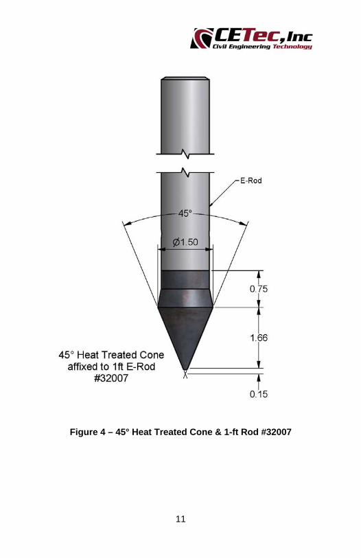
Figure 4 – 45°Heat Treated Cone & 1-ft Rod #32007
Figure 5 – DCP Soil Relationships Reference Chart

3
1. General Background & History
The Standard Penetration Test (SPT) has its origins in the experimental observation of blows per unit measure of driving casing. The SPT method requires a mechanized piece of equipment, i.e. soil auger drill, to raise and drop a 140lb mass a distance of 30-in. Numerous methods have been developed to scale down the SPT such that hand operated tools could be used at shallow depths where confined spaces or the need for expedience excludes the use of a mechanized SPT device.
The late Prof. George Sowers developed one of the more common devices in 1959 for field exploration and the evaluation of lightly loaded shallow spread footings during the construction phase. For the original theory the reader is encouraged to consult the following reference: George F. Sowers and Charles S. Hedges, Dynamic Cone for Shallow In-Situ Penetration Testing, Vane Shear and Cone Penetrations Resistance Testing of In-Situ Soils, ASTM STP 399, American Society and Materials. Copies can be purchased from ASTM, 100 Barr Harbor Drive, West Conshohocken, PA 19428 - (610) 832-9500 Fax: (610) 832-9555.
2. Description of the Device
The equipment developed is a Dynamic Cone Penetrometer Device (DCP - Fig 3), which utilizes a 15-lb steel mass free falling 20” to strike an anvil attached to an E-rod slide. Upon striking the anvil block, a 1.5” diameter 45° drive point cone (Fig 4), which has been seated in the bottom of an augered hole, is driven into the soil material. The device has been used extensively in the Southeastern region of the USA and calibrated with standard SPT results. The original cone penetration relationships by Sowers are shown in the chart in Figure 5. Similar correlations could be developed for soils of other regions and of differing geologic derivation.

4
3. Safety and Proper Use
The proper use, care, and instructions for this instrument must be strictly followed.
Any use other than for that specified is considered improper and the manufacturer cannot be held responsible for damages caused by the incorrect use of the equipment.
Always keep the device in a clean, properly maintained condition. Do not tamper with the device for any reason.
Keep this manual in a secure location for future reference.
4. Operating Instructions
a. The DCP test is normally performed in the bottom of a hand augered hole generally 3” to 6” in diameter.
b. Begin by using a basic hand auger set to auger to the desired test depth. Take care to remove as much of the bottom cuttings as practical. Observe the auger cuttings to identify and visually classify the soil.
⚠ Warning: Handle the Dynamic Cone Penetrometer with extreme care. Hold and transport the DCP only by the using the handle. Do not grasp the E-rod between the pull out anvil and the driving anvil as the 15·lbm sliding weight moves easily along this part of the rod and can severely pinch your fingers/hand.
c. Attach the 45° Drive Point Cone & 1-ft rod assembly to an extension (or extensions if required) and tighten securely. Attach extension(s) and point assembly to the sliding drive hammer device. Gently lower the sliding drive hammer, required number of extension rods and the drive point assembly to the bottom of the borehole. Do not drop the DCP into the hole, as the weight of the assembly will cause the point to prematurely penetrate the bottom of the hole.
5
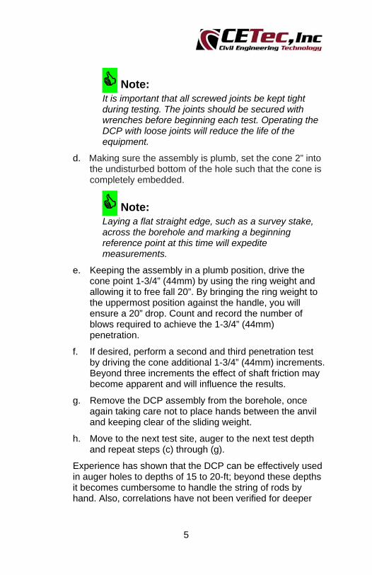
Note: It is important that all screwed joints be kept tight during testing. The joints should be secured with wrenches before beginning each test. Operating the DCP with loose joints will reduce the life of the equipment.
d. Making sure the assembly is plumb, set the cone 2” into the undisturbed bottom of the hole such that the cone is completely embedded.
Note: Laying a flat straight edge, such as a survey stake, across the borehole and marking a beginning reference point at this time will expedite measurements.
e. Keeping the assembly in a plumb position, drive the cone point 1-3/4” (44mm) by using the ring weight and allowing it to free fall 20”. By bringing the ring weight to the uppermost position against the handle, you will ensure a 20” drop. Count and record the number of blows required to achieve the 1-3/4” (44mm) penetration.
f. If desired, perform a second and third penetration test by driving the cone additional 1-3/4” (44mm) increments. Beyond three increments the effect of shaft friction may become apparent and will influence the results.
g. Remove the DCP assembly from the borehole, once again taking care not to place hands between the anvil and keeping clear of the sliding weight.
h. Move to the next test site, auger to the next test depth and repeat steps (c) through (g).
Experience has shown that the DCP can be effectively used in auger holes to depths of 15 to 20-ft; beyond these depths it becomes cumbersome to handle the string of rods by hand. Also, correlations have not been verified for deeper

6
depths where energy losses from thread joints and rod inertia have not been considered.
5. Equipment Inspection Prior to Test
a. Always inspect the Cone point carefully before performing any tests. The cone has been hardened but requires occasional replacement. The cone should be replaced when its diameter has been reduced significantly (>3%) or when its surface is badly gouged or the tip is very blunt.
b. Check the pin that attaches the Cone point to the 1-ft E-rod adaptor.
c. Check and make sure the spot where the 15-lbm weight contacts the drive anvil is not worn excessively.
d. Check and make sure there are no fractures or cracking in the weld of the drive anvil to the E-rod slide.
e. Check the male and female E-rod threads for wear and fractures.
f. Verify the handle is tight on the E-rod slide.
g. If needed, the handle can be unscrewed from the E-rod slide to allow for the weight to be removed for verification.
6. Equipment Storage
a. To ensure the equipment is ready for use, always carry out the following checks before storing:
Check that Drive Point is in functioning condition; clean with no deep grooves, scratches, or gouges.
Verify weight drop height. Quick check of male & female E-rod threads. Quick check of welds. Clean and wipe down all dirt, dust, and mud from
unit.

7
7. Replacement and Optional Equipment
Figure 1 – DCP Drive Tube Head & Sampler Tube

8
Replacement & Optional Parts for Dynamic Cone Penetrometer Set
Part # Qty Description
32004 Sliding Mass DCP Kit (consists of 3 items below)
32005 1 Sliding Drive Hammer Device
32007 1 45o Heat Treated Point affixed to 1ft E‐Rod
32010 4 2.5ft E‐Rod Extension
32009 1.0ft E‐Rod Extension
32010 2.5ft E‐Rod Extension
32011 5.0ft E‐Rod Extension
32007 45o Heat Treated Point affixed to 1ft E‐Rod
32008 Replacement Heat Treated Point w/ attachment Pin
32005 Sliding Drive Hammer Device
32027 DCP Drive Tube "Shelby" Head
33019 Galvanized Sampler Tube, 3"dia x 12" Long (9/bx)
800207 Plastic End Caps for 3"dia Sampler Tubes
31023 Basic Hand Auger Set (consists of 3 items below)
31027 1 3.25" Auger Head w/ D‐clip
31007 1 36" Extension w/ D‐clip
31011 1 Tee Handle, Basic
31024 Basic Stainless Hand Auger Set (consists of 3 items below)
31028 1 3.25" Auger Head w/ D‐clip, Stainless
31009 1 36" Extension w/ D‐clip, Stainless
31012 1 Tee Handle, Basic, Stainless
31029 3.25" Windowed Auger Head w/ D‐clip
31030 3.25" Windowed Auger Head w/ D‐clip, Stainless
31001 Replacement D‐clip
31002 Replacement D‐clip, Stainless
Figure 2 – Replacement & Optional Parts Chart

9
8. Warranty
CETEC, Inc. warrants its products to be free from defects in material or workmanship and that the products supplied are suitable for the standard purpose for which they are designed. For any warranty claim, the purchaser must obtain a Return Authorization prior to returning the product and is responsible for the return transportation charges to CETEC, Inc. The exclusive remedy for this warranty will be made by CETEC, Inc. which at its discretion may repair or replace the product. For the warranty of this product please refer to the website or catalog.
This warranty excludes damage from or repairs resulting from neglect, abuse, normal wear and conditions, modifications or alterations, repairs attempted by anyone other than CETEC, Inc. and failure to comply with installation, maintenance or operating instructions. Also excluded are damages caused by acts of God or other occurrences beyond our control. CETEC, Inc. will not be held responsible for and will not pay for any lost profits incidental, consequential, or special damages.

10
9. Appendix
Figure 3 – Sliding Drive Hammer Device #32005
11
Figure 4 – 45° Heat Treated Cone & 1-ft Rod #32007

12
Figure 5 – DCP Soil Relationships Reference Chart