30rb-3t
TRANSCRIPT
Manufacturer reserves the right to discontinue, or change at any time, specifications or designs without notice and without incurring obligations.Catalog No. 04-53300028-01 Printed in U.S.A. Form 30RB-3T Pg 1 12-09 Replaces: 30RB-2T
Controls, Start-Up, Operation, Service and Troubleshooting
CONTENTSPage
SAFETY CONSIDERATIONS . . . . . . . . . . . . . . . . . . . . . . . . .2GENERAL . . . . . . . . . . . . . . . . . . . . . . . . . . . . . . . . . . . . . . . . . 2-5Conventions Used in This Manual . . . . . . . . . . . . . . . . . . .3Basic Control Usage. . . . . . . . . . . . . . . . . . . . . . . . . . . . . . . . .3• SCROLLING MARQUEE DISPLAY• ACCESSORY NAVIGATOR™ DISPLAY MODULECONTROLS. . . . . . . . . . . . . . . . . . . . . . . . . . . . . . . . . . . . . . . 5-43General . . . . . . . . . . . . . . . . . . . . . . . . . . . . . . . . . . . . . . . . . . . . . .5Main Base Board (MBB) . . . . . . . . . . . . . . . . . . . . . . . . . . . . .5Scroll Protection Module (SPM). . . . . . . . . . . . . . . . . . . . . .7Electronic Expansion Valve (EXV) Board . . . . . . . . . . . .8Fan Boards . . . . . . . . . . . . . . . . . . . . . . . . . . . . . . . . . . . . . . . . . .9Reverse Rotation Board . . . . . . . . . . . . . . . . . . . . . . . . . . . .13• DIAL SETTINGS• PHASE REVERSAL PROTECTION• PHASE LOSS AND UNDER-VOLTAGE
PROTECTIONEnable-Off-Remote Contact Switch . . . . . . . . . . . . . . . . .13Emergency On/Off Switch . . . . . . . . . . . . . . . . . . . . . . . . . .13Energy Management Module (EMM) . . . . . . . . . . . . . . . .14Energy Management Module Heat Reclaim (EMM HR) . . . . . . . . . . . . . . . . . . . . . . . . . .15Local Equipment Network . . . . . . . . . . . . . . . . . . . . . . . . . .16Board Addresses . . . . . . . . . . . . . . . . . . . . . . . . . . . . . . . . . . .16Control Module Communication . . . . . . . . . . . . . . . . . . . .16• RED LED• GREEN LED• YELLOW LEDCarrier Comfort Network® (CCN) Interface . . . . . . . . . .16Configuration Options . . . . . . . . . . . . . . . . . . . . . . . . . . . . . .17• MINIMUM LOAD CONTROL• RAMP LOADING• MINUTES OFF TIMEDual Chiller Control . . . . . . . . . . . . . . . . . . . . . . . . . . . . . . . .17Capacity Control . . . . . . . . . . . . . . . . . . . . . . . . . . . . . . . . . . .20• CAPACITY CONTROL OVERRIDESHead Pressure Control . . . . . . . . . . . . . . . . . . . . . . . . . . . . .24• LOW AMBIENT TEMPERATURE HEAD PRESSURE
CONTROL OPTION• LOW AMBIENT TEMPERATURE HEAD PRESSURE
CONTROL OPERATING INSTRUCTIONSCooler Pump Control . . . . . . . . . . . . . . . . . . . . . . . . . . . . . . .31Machine Control Methods . . . . . . . . . . . . . . . . . . . . . . . . . .32• SWITCH CONTROL• TIME SCHEDULE• CCN CONTROL• UNIT RUN STATUSCooling Set Point Selection . . . . . . . . . . . . . . . . . . . . . . . .33• SET POINT 1• SET POINT 2• 4 TO 20 mA INPUT• DUAL SWITCH• SET POINT OCCUPANCYTemperature Reset . . . . . . . . . . . . . . . . . . . . . . . . . . . . . . . . .33Demand Limit . . . . . . . . . . . . . . . . . . . . . . . . . . . . . . . . . . . . . .41• 2-STEP SWITCH CONTROLLED
Page• EXTERNALLY POWERED (4 to 20 mA Controlled)• CCN LOADSHED CONTROLLEDRemote Alarm and Alert Relays . . . . . . . . . . . . . . . . . . . . 41PRE-START-UP . . . . . . . . . . . . . . . . . . . . . . . . . . . . . . . . . . 43,44System Check . . . . . . . . . . . . . . . . . . . . . . . . . . . . . . . . . . . . . . 43START-UP . . . . . . . . . . . . . . . . . . . . . . . . . . . . . . . . . . . . . . . 44,45Actual Start-Up . . . . . . . . . . . . . . . . . . . . . . . . . . . . . . . . . . . . . 44Operating Limitations . . . . . . . . . . . . . . . . . . . . . . . . . . . . . . 44• TEMPERATURES• VOLTAGE• MINIMUM FLUID LOOP VOLUME• FLOW RATE REQUIREMENTSOPERATION . . . . . . . . . . . . . . . . . . . . . . . . . . . . . . . . . . . . . 45-49Sequence of Operation . . . . . . . . . . . . . . . . . . . . . . . . . . . . . 45Dual Chiller Sequence of Operation . . . . . . . . . . . . . . . . 45Operating Modes . . . . . . . . . . . . . . . . . . . . . . . . . . . . . . . . . . . 46Optional Heat Reclaim Module . . . . . . . . . . . . . . . . . . . . . 49SERVICE . . . . . . . . . . . . . . . . . . . . . . . . . . . . . . . . . . . . . . . . 49-57Electronic Expansion Valve (EXV) . . . . . . . . . . . . . . . . . . 49• EXV TROUBLESHOOTING PROCEDURECooler. . . . . . . . . . . . . . . . . . . . . . . . . . . . . . . . . . . . . . . . . . . . . . 51• FREEZE PROTECTION• LOW FLUID TEMPERATURE• LOSS OF FLUID FLOW PROTECTION• TUBE PLUGGING• RETUBING• TIGHTENING COOLER HEAD BOLTS• CHILLED WATER FLOW SWITCHRTPF Condenser Coil Maintenance and Cleaning
Recommendations . . . . . . . . . . . . . . . . . . . . . . . . . . . . . . . 53• REMOVE SURFACE LOADED FIBERS• PERIODIC CLEAN WATER RINSE• ROUTINE CLEANING OF COIL SURFACESMCHX Condenser Coil Maintenance and Cleaning
Recommendations . . . . . . . . . . . . . . . . . . . . . . . . . . . . . . . 55Condenser Fans. . . . . . . . . . . . . . . . . . . . . . . . . . . . . . . . . . . . 55Refrigerant Circuit. . . . . . . . . . . . . . . . . . . . . . . . . . . . . . . . . . 56• LEAK TESTING• REFRIGERANT CHARGESafety Devices . . . . . . . . . . . . . . . . . . . . . . . . . . . . . . . . . . . . . 56• COMPRESSOR PROTECTION• CRANKCASE HEATERSRelief Devices . . . . . . . . . . . . . . . . . . . . . . . . . . . . . . . . . . . . . . 56• HIGH-SIDE PROTECTION• LOW-SIDE PROTECTIONCompressors. . . . . . . . . . . . . . . . . . . . . . . . . . . . . . . . . . . . . . . 56• COMPRESSOR REPLACEMENT• OIL CHARGE• SYSTEM BURNOUT CLEANUP PROCEDUREMAINTENANCE. . . . . . . . . . . . . . . . . . . . . . . . . . . . . . . . . . . . . 57Recommended Maintenance Schedule . . . . . . . . . . . . . 57TROUBLESHOOTING. . . . . . . . . . . . . . . . . . . . . . . . . . . . 57-81Alarms and Alerts . . . . . . . . . . . . . . . . . . . . . . . . . . . . . . . . . . 57• DIAGNOSTIC ALARM CODES AND POSSIBLE
CAUSES
AQUASNAP®
30RB060-390Air-Cooled Liquid Chillers
2
CONTENTS (cont)Page
Sensors . . . . . . . . . . . . . . . . . . . . . . . . . . . . . . . . . . . . . . . . . . . . 71Thermistors . . . . . . . . . . . . . . . . . . . . . . . . . . . . . . . . . . . . . . . . 71• COOLER LEAVING FLUID SENSOR• COOLER ENTERING FLUID SENSOR• DUAL CHILLER LWT• COMPRESSOR RETURN GAS TEMPERATURE• OUTDOOR AIR TEMPERATURE• REMOTE SPACE TEMPERATUREService Test. . . . . . . . . . . . . . . . . . . . . . . . . . . . . . . . . . . . . . . . 74APPENDIX A — LOCAL DISPLAY TABLES . . . . . . 82-93APPENDIX B — CCN TABLES . . . . . . . . . . . . . . . . . . 94-107APPENDIX C — CCN ALARM DESCRIPTION . . 108-111APPENDIX D — R-410A PRESSURE VS.
TEMPERATURE CHART. . . . . . . . . . . . . . . . . . . . . . . . . 112INDEX. . . . . . . . . . . . . . . . . . . . . . . . . . . . . . . . . . . . . . . . . .113,114START-UP CHECKLIST FOR 30RB LIQUID CHILLER . . . . . . . . . . . . . . . . . . . . . . . . CL-1 to CL-9
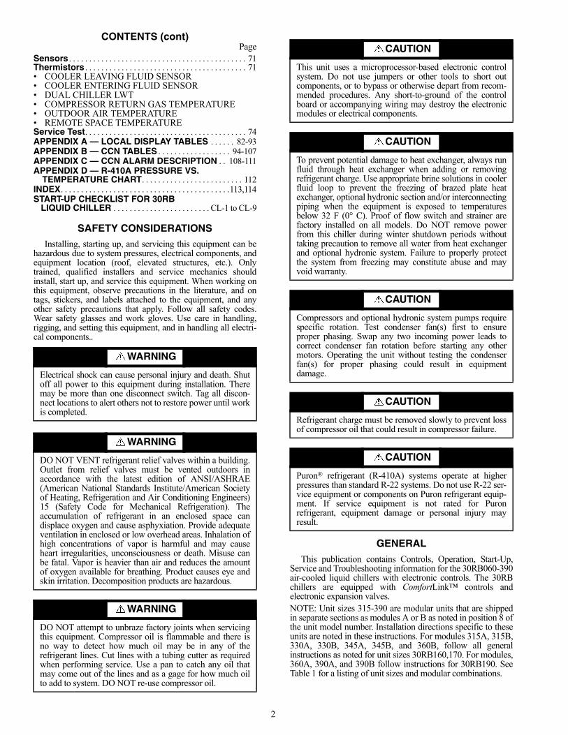
SAFETY CONSIDERATIONSInstalling, starting up, and servicing this equipment can be
hazardous due to system pressures, electrical components, andequipment location (roof, elevated structures, etc.). Onlytrained, qualified installers and service mechanics shouldinstall, start up, and service this equipment. When working onthis equipment, observe precautions in the literature, and ontags, stickers, and labels attached to the equipment, and anyother safety precautions that apply. Follow all safety codes.Wear safety glasses and work gloves. Use care in handling,rigging, and setting this equipment, and in handling all electri-cal components..
GENERAL
This publication contains Controls, Operation, Start-Up,Service and Troubleshooting information for the 30RB060-390air-cooled liquid chillers with electronic controls. The 30RBchillers are equipped with ComfortLink™ controls andelectronic expansion valves.NOTE: Unit sizes 315-390 are modular units that are shippedin separate sections as modules A or B as noted in position 8 ofthe unit model number. Installation directions specific to theseunits are noted in these instructions. For modules 315A, 315B,330A, 330B, 345A, 345B, and 360B, follow all generalinstructions as noted for unit sizes 30RB160,170. For modules,360A, 390A, and 390B follow instructions for 30RB190. SeeTable 1 for a listing of unit sizes and modular combinations.
WARNING
Electrical shock can cause personal injury and death. Shutoff all power to this equipment during installation. Theremay be more than one disconnect switch. Tag all discon-nect locations to alert others not to restore power until workis completed.
WARNING
DO NOT VENT refrigerant relief valves within a building.Outlet from relief valves must be vented outdoors inaccordance with the latest edition of ANSI/ASHRAE(American National Standards Institute/American Societyof Heating, Refrigeration and Air Conditioning Engineers)15 (Safety Code for Mechanical Refrigeration). Theaccumulation of refrigerant in an enclosed space candisplace oxygen and cause asphyxiation. Provide adequateventilation in enclosed or low overhead areas. Inhalation ofhigh concentrations of vapor is harmful and may causeheart irregularities, unconsciousness or death. Misuse canbe fatal. Vapor is heavier than air and reduces the amountof oxygen available for breathing. Product causes eye andskin irritation. Decomposition products are hazardous.
WARNING
DO NOT attempt to unbraze factory joints when servicingthis equipment. Compressor oil is flammable and there isno way to detect how much oil may be in any of therefrigerant lines. Cut lines with a tubing cutter as requiredwhen performing service. Use a pan to catch any oil thatmay come out of the lines and as a gage for how much oilto add to system. DO NOT re-use compressor oil.
CAUTION
This unit uses a microprocessor-based electronic controlsystem. Do not use jumpers or other tools to short outcomponents, or to bypass or otherwise depart from recom-mended procedures. Any short-to-ground of the controlboard or accompanying wiring may destroy the electronicmodules or electrical components.
CAUTION
To prevent potential damage to heat exchanger, always runfluid through heat exchanger when adding or removingrefrigerant charge. Use appropriate brine solutions in coolerfluid loop to prevent the freezing of brazed plate heatexchanger, optional hydronic section and/or interconnectingpiping when the equipment is exposed to temperaturesbelow 32 F (0° C). Proof of flow switch and strainer arefactory installed on all models. Do NOT remove powerfrom this chiller during winter shutdown periods withouttaking precaution to remove all water from heat exchangerand optional hydronic system. Failure to properly protectthe system from freezing may constitute abuse and mayvoid warranty.
CAUTION
Compressors and optional hydronic system pumps requirespecific rotation. Test condenser fan(s) first to ensureproper phasing. Swap any two incoming power leads tocorrect condenser fan rotation before starting any othermotors. Operating the unit without testing the condenserfan(s) for proper phasing could result in equipmentdamage.
CAUTION
Refrigerant charge must be removed slowly to prevent lossof compressor oil that could result in compressor failure.
CAUTION
Puron® refrigerant (R-410A) systems operate at higherpressures than standard R-22 systems. Do not use R-22 ser-vice equipment or components on Puron refrigerant equip-ment. If service equipment is not rated for Puronrefrigerant, equipment damage or personal injury mayresult.

3
NOTE: The nameplate for modular units contains only the firsttwo digits in the model number. For example, 315A and 315Bnameplates read 31A and 31B.
Table 1 — Modular Unit Combinations
NOTE: An “A” in the model number indicates the design series.
Conventions Used in This Manual — The follow-ing conventions for discussing configuration points for thelocal display (scrolling marquee or Navigator™ accessory)will be used in this manual.
Point names will be written with the mode name first, thenany sub-modes, then the point name, each separated by anarrow symbol (. Names will also be shown in boldand italics. As an example, the Lead/Lag Circuit Select Point,which is located in the Configuration mode, Option sub-mode,would be written as Configuration OPTNLLCS.
This path name will show the user how to navigate throughthe local display to reach the desired configuration. The userwould scroll through the modes and sub-modes using the
and keys. The arrow symbol in the path name repre-sents pressing to move into the next level of themenu structure.
When a value is included as part of the path name, it will beshown at the end of the path name after an equals sign. If thevalue represents a configuration setting, an explanation willbe shown in parenthesis after the value. As an example,ConfigurationOPTNLLCS = 1 (Circuit A leads).
Pressing the and keys simultaneouslywill scroll an expanded text description of the point name orvalue across the display. The expanded description is shown inthe local display tables but will not be shown with the pathnames in text.
The CCN (Carrier Comfort Network®) point names are alsoreferenced in the local display tables for users configuring theunit with CCN software instead of the local display. The CCNtables are located in Appendix B of the manual.
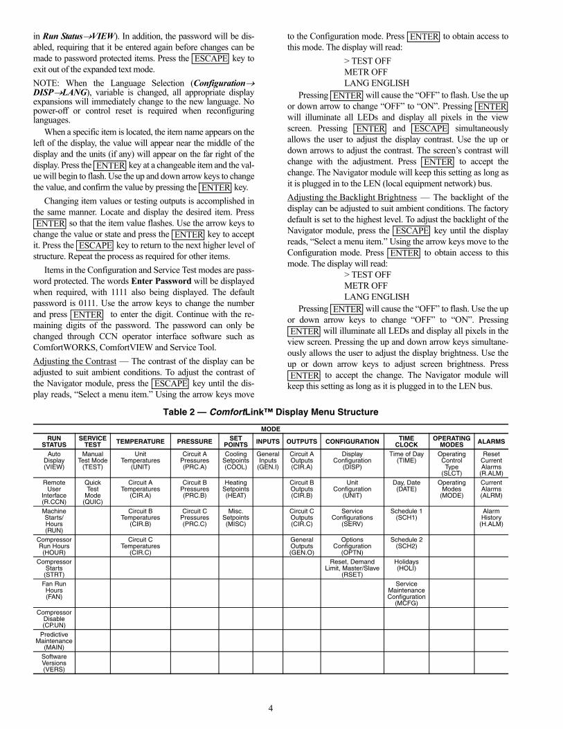
Basic Control UsageSCROLLING MARQUEE DISPLAY — The scrolling mar-quee display is the standard interface display to the ComfortLinkControl System for 30RB units. The display has up and downarrow keys, an key, and an key. Thesekeys are used to navigate through the different levels of thedisplay structure. Press the key until the highestoperating level is displayed to move through the top 11 modelevels indicated by LEDs (light-emitting diodes) on the left sideof the display. See Fig. 1.
Once within a mode or sub-mode, pressing the and keys simultaneously will put the scrollingmarquee display into expanded text mode where the full mean-ing of all sub-modes, items and their values can be displayedfor the current selection. Press the and keys to return the scrolling marquee display to its default menuof rotating display items (those items in Run StatusVIEW).In addition, the password will be disabled, requiring that it beentered again before changes can be made to password
protected items. Press the key to exit out of the ex-panded text mode.
NOTE: When the Language Selection (ConfigurationDISPLANG), variable is changed, all appropriate displayexpansions will immediately change to the new language. Nopower-off or control reset is required when reconfiguringlanguages.
When a specific item is located, the item name alternateswith the value. Press the key at a changeable itemand the value will be displayed. Press again and thevalue will begin to flash indicating that the value can bechanged. Use the up and down arrow keys to change the value,and confirm the value by pressing the key.
Changing item values or testing outputs is accomplished inthe same manner. Locate and display the desired item. Press
so that the item value flashes. Use the arrow keys tochange the value or state and press the key to acceptit. Press the key to return to the next higher level ofstructure. Repeat the process as required for other items.
Items in the Configuration and Service Test modes are pass-word protected. The words ‘PASS’ and ‘WORD’ will alternateon the display when required. The default password is 0111.Press and the 1111 password will be displayed. Press
again and the first digit will begin to flash. Use thearrow keys to change the number and press to acceptthe digit. Continue with the remaining digits of the password.The password can only be changed through CCN operator in-terface software such as ComfortWORKS®, ComfortVIEW™and Service Tool.
See Table 2 and Appendix A for further details.
ACCESSORY NAVIGATOR™ DISPLAY MODULE —The Navigator module provides a mobile user interface to theComfortLink™ control system, which is only available as afield-installed accessory. The display has up and down arrowkeys, an key, and an key. These keys areused to navigate through the different levels of the displaystructure. Press the key until ‘Select a Menu Item’is displayed to move through the top 11 mode levels indicatedby LEDs on the left side of the display. See Fig. 2.
Once within a Mode or sub-mode, a “>” indicates the cur-rently selected item on the display screen. Pressing the
and keys simultaneously will put the Nav-igator module into expanded text mode where the full meaningof all sub-modes, items and their values can be displayed. Press-ing the and keys when the display says‘Select Menu Item’ (Mode LED level) will return the Navigatormodule to its default menu of rotating display items (those items
UNIT SIZE MODULE A MODULE B30RBA315 30RBA160 30RBA16030RBA330 30RBA170 30RBA16030RBA345 30RBA170 30RBA17030RBA360 30RBA190 30RBA17030RBA390 30RBA190 30RBA190
ENTER
ESCAPE ENTER
ENTER ESCAPE
ESCAPE
ENTERESCAPE
ENTER ESCAPE
ESCAPE
Run Status
Service Test
Temperature
Pressures
Setpoints
Inputs
Outputs
Configuration
Time Clock
Operating Modes
Alarms
Alarm Status
ENTER
MODE
ESCAPE
Fig. 1 — Scrolling Marquee Display
ENTERENTER
ENTER
ENTERENTER
ESCAPE
ENTERENTER
ENTER
ENTER ESCAPE
ESCAPE
ENTER ESCAPE
ENTER ESCAPE
4
in Run StatusVIEW). In addition, the password will be dis-abled, requiring that it be entered again before changes can bemade to password protected items. Press the key toexit out of the expanded text mode.
NOTE: When the Language Selection (ConfigurationDISPLANG), variable is changed, all appropriate displayexpansions will immediately change to the new language. Nopower-off or control reset is required when reconfiguringlanguages.
When a specific item is located, the item name appears on theleft of the display, the value will appear near the middle of thedisplay and the units (if any) will appear on the far right of thedisplay. Press the key at a changeable item and the val-ue will begin to flash. Use the up and down arrow keys to changethe value, and confirm the value by pressing the key.
Changing item values or testing outputs is accomplished inthe same manner. Locate and display the desired item. Press
so that the item value flashes. Use the arrow keys tochange the value or state and press the key to acceptit. Press the key to return to the next higher level ofstructure. Repeat the process as required for other items.
Items in the Configuration and Service Test modes are pass-word protected. The words Enter Password will be displayedwhen required, with 1111 also being displayed. The defaultpassword is 0111. Use the arrow keys to change the numberand press to enter the digit. Continue with the re-maining digits of the password. The password can only bechanged through CCN operator interface software such asComfortWORKS, ComfortVIEW and Service Tool.
Adjusting the Contrast — The contrast of the display can beadjusted to suit ambient conditions. To adjust the contrast ofthe Navigator module, press the key until the dis-play reads, “Select a menu item.” Using the arrow keys move
to the Configuration mode. Press to obtain access tothis mode. The display will read:
> TEST OFFMETR OFFLANG ENGLISH
Pressing will cause the “OFF” to flash. Use the upor down arrow to change “OFF” to “ON”. Pressing will illuminate all LEDs and display all pixels in the viewscreen. Pressing and simultaneouslyallows the user to adjust the display contrast. Use the up ordown arrows to adjust the contrast. The screen’s contrast willchange with the adjustment. Press to accept thechange. The Navigator module will keep this setting as long asit is plugged in to the LEN (local equipment network) bus.
Adjusting the Backlight Brightness — The backlight of thedisplay can be adjusted to suit ambient conditions. The factorydefault is set to the highest level. To adjust the backlight of theNavigator module, press the key until the displayreads, “Select a menu item.” Using the arrow keys move to theConfiguration mode. Press to obtain access to thismode. The display will read:
> TEST OFFMETR OFFLANG ENGLISH
Pressing will cause the “OFF” to flash. Use the upor down arrow keys to change “OFF” to “ON”. Pressing
will illuminate all LEDs and display all pixels in theview screen. Pressing the up and down arrow keys simultane-ously allows the user to adjust the display brightness. Use theup or down arrow keys to adjust screen brightness. Press
to accept the change. The Navigator module willkeep this setting as long as it is plugged in to the LEN bus.
Table 2 — ComfortLink™ Display Menu Structure
ESCAPE
ENTER
ENTER
ENTERENTER
ESCAPE
ENTER
ESCAPE
ENTER
ENTERENTER
ENTER ESCAPE
ENTER
ESCAPE
ENTER
ENTER
ENTER
ENTER
MODERUN
STATUSSERVICE
TEST TEMPERATURE PRESSURE SETPOINTS INPUTS OUTPUTS CONFIGURATION TIME
CLOCKOPERATING
MODES ALARMS
AutoDisplay(VIEW)
ManualTest Mode
(TEST)
UnitTemperatures
(UNIT)
Circuit APressures(PRC.A)
CoolingSetpoints(COOL)
GeneralInputs
(GEN.I)
Circuit AOutputs(CIR.A)
DisplayConfiguration
(DISP)
Time of Day(TIME)
OperatingControl
Type(SLCT)
ResetCurrentAlarms
(R.ALM)Remote
UserInterface(R.CCN)
QuickTest
Mode(QUIC)
Circuit ATemperatures
(CIR.A)
Circuit BPressures(PRC.B)
HeatingSetpoints(HEAT)
Circuit BOutputs(CIR.B)
UnitConfiguration
(UNIT)
Day, Date(DATE)
OperatingModes
(MODE)
CurrentAlarms(ALRM)
MachineStarts/Hours(RUN)
Circuit BTemperatures
(CIR.B)
Circuit CPressures(PRC.C)
Misc. Setpoints(MISC)
Circuit COutputs(CIR.C)
ServiceConfigurations
(SERV)
Schedule 1(SCH1)
AlarmHistory
(H.ALM)
CompressorRun Hours
(HOUR)
Circuit CTemperatures
(CIR.C)
GeneralOutputs(GEN.O)
OptionsConfiguration
(OPTN)
Schedule 2(SCH2)
CompressorStarts
(STRT)
Reset, Demand Limit, Master/Slave
(RSET)
Holidays(HOLI)
Fan RunHours(FAN)
ServiceMaintenanceConfiguration
(MCFG)Compressor
Disable(CP.UN)
PredictiveMaintenance
(MAIN)SoftwareVersions(VERS)

5
CONTROLS
General — The 30RB air-cooled liquid chillers contain theComfortLink™ electronic control system that controls and
monitors all operations of the chiller. The control system iscomposed of several components as listed in the following sec-tions. All machines have at the very least a main base board(MBB), scrolling marquee display, electric expansion valveboard (EXV), fan board, one scroll protection module (SPM)per compressor, Emergency On/Off switch, an Enable-Off- Re-mote Contact switch and a reverse rotation board.
Main Base Board (MBB) — The MBB is the heart ofthe ComfortLink control system, which contains the majorportion of operating software and controls the operation of themachine. See Fig. 3. The MBB continuously monitors input/output channel information received from its inputs and fromall other modules. The MBB receives inputs from status andfeedback switches, pressure transducers and thermistors. TheMBB also controls several outputs. Some inputs and outputs tocontrol the machine are located on other boards, but are trans-mitted to or from the MBB via the internal communicationsbus. Information is transmitted between modules via a 3-wirecommunication bus or LEN (Local Equipment Network). TheCCN (Carrier Comfort Network) bus is also supported. Con-nections to both LEN and CCN buses are made at TB3. For acomplete description of main base board inputs and outputsand their channel identifications, see Table 3.
Run StatusService TestTemperaturesPressures
SetpointsInputs
OutputsConfigurationTime Clock
Operating ModesAlarms
ENTER
ESC
MODEAlarm Status
ComfortLink
Fig. 2 — Accessory Navigator Display Module
221
221
221
221
195
195
195
195
195
195
195C
H1
CH
2C
H3
CH
4
CH11 CH12
LOCATION OFSERIAL NUMBER
CH13 CH14 CH15A
J4ANALOGINPUTSJ3
J2CJ2BJ15
J1A
J9D
+ G –
DISCRETEINPUTS
J5A
C16A
CH15BC
CCH16B
11 C16J2A
TR1 TR2 TR3 TR4 TR5
CH19 CH20 CH21 CH22 CH23 CH24 CH25 CH26
J8
CH17 CH18
J5B J5C
TH
ER
MIS
ER
S
PR
ES
SU
RE
S
CH
5C
H6
CH
7C
H8
CH
9
J7A
J7B
J7C
J7D
RELAYOUTPUTS
MOV1
C41 C42 C43
C32 C33 C34 C35
12/1112/11
J1019 J12
J13 + G -
STATUS
J9A
K1 K2D15
J6
CCN
CH10
+ G –SIO
(LEN)
J9C J9B
+ G –
Fig. 3 — Main Base Board

6
Table 3 — Main Base Board Inputs and Outputs
* Controls discharge and liquid line isolation soleniods for 30RB120-190 brine units only.
DESCRIPTION INPUT/OUTPUT I/O TYPE SCROLLING MARQUEEPOINT NAME
CONNECTION POINTPin Notation
Power (24 vac supply) — — —
MBB-J1, MBB-J1A, MBB-J1B
11 24 vac12 Ground
Local Equipment Network — — —
MBB-J9A, MBB-J9B, MBB-J9C, MBB-J9D+G-
Carrier Comfort Network® (CCN) — — —
MBB-J12+G-
External Chilled Water Pump Interlock PMPI Switch INPUTSGEN.ILOCK MBB-J4-CH15A
Chilled Water Flow Switch CWFS Switch INPUTSGEN.ILOCKMBB-J5A-CH15B
15B
Demand Limit Switch #1 Demand Limit SW1 Switch INPUTSGEN.IDLS1 MBB-J4-CH13
Circuit A Discharge Pressure Transducer DPTA Pressure Transducer
(0-5 VDC) PRESSUREPRC.ADP.A
MBB-J7A-CH65V 5 vdc Ref.
S Signal
R Return
Circuit B Discharge Pressure Transducer DPTB Pressure Transducer
(0-5 VDC) PRESSUREPRC.BDP.B
MBB-J7C-CH85V 5 vdc Ref.S SignalR Return
Dual Chiller LWT Thermistor DUAL 5k Thermistor TEMPERATUREUNITCHWS MBB-J6-CH3
Dual Set Point Input Dual Set Point Switch INPUTSGEN.IDUAL MBB-J4-CH12Entering Water Thermistor EWT 5k Thermistor TEMPERATUREUNITEWT MBB-J6-CH2Leaving Water Thermistor LWT 5k Thermistor TEMPERATUREUNITLWT MBB-J6-CH1
Outdoor Air Thermistor OAT 5k Thermistor TEMPERATUREUNITOAT MBB-J6-CH4
Pump #1 InterlockPump #2 Interlock
PMP1PMP2 Switch INPUTSGEN.IPUMP
MBB-J5C-CH1818
C
Reverse Rotation Board Reverse Rotation Board Switch INPUTSGEN.IELECMBB-J5A-CH16B
16B
Circuit A Suction Pressure Transducer SPTA Pressure Transducer
(0-5 VDC) PRESSUREPRC.ASP.A
MBB-J7B-CH75V 5 vdc Ref.S SignalR Return
Circuit B Suction Pressure Transducer SPTB Pressure Transducer
(0-5 VDC) PRESSUREPR.BSP.B
MBB-J7D-CH95V 5 vdc Ref.S SignalR Return
Unit Status Remote Contact-Off-Enable Switch INPUTSGEN.IONOF MBB-J4-CH11
Alarm Relay ALM R Relay OUTPUTSGEN.OALRM MBB-J3-CH24Alert Relay ALT R Relay OUTPUTSGEN.OALRT MBB-J3-CH25
Cooler Heater CL-HT TRIAC OUTPUTSGEN.OCO.HT MBB-J2B-CH21Circuit A Minimum
Load Control* MLV-A TRIAC OUTPUTSCIR.AHGB.A MBB-J2C-CH22
Circuit B Minimum Load Control* MLV-B TRIAC OUTPUTSCIR.BHGB.B MBB-J2C-CH23
Pump #1 Starter PMP1 TRIAC OUTPUTSGEN.OPMP.1 MBB-J2A-CH19Pump #2 Starter PMP2 TRIAC OUTPUTSGEN.OPMP.2 MBB-J2A-CH20
Ready Relay RDY R Relay OUTPUTSGEN.OREDY MBB-J3-CH26

7
Scroll Protection Module (SPM) — There is oneSPM per compressor and it is responsible for controlling thatcompressor. See Fig. 4. The device controls the compressorcontactor and the compressor crankcase heater. The SPM mod-ule also monitors the compressor motor temperature, and cir-cuit high pressure switch. The SPM responds to commandsfrom the MBB (main base board) and sends the MBB theresults of the channels it monitors via the LEN (LocalEquipment Network). See below for SPM board address infor-mation. See Table 4 for SPM inputs and outputs.
SPM-A1 DIP Switch 1 2 3 4 5 6 7 8
Address: ON OFF OFF OFF ON OFF OFF OFF
SPM-A2 DIP Switch 1 2 3 4 5 6 7 8
Address: OFF ON OFF OFF ON OFF OFF OFF
SPM-A3 DIP Switch 1 2 3 4 5 6 7 8
Address: OFF OFF ON OFF ON OFF OFF OFF
SPM-A4 DIP Switch 1 2 3 4 5 6 7 8
Address: OFF OFF OFF ON ON OFF OFF OFF
SPM-B1 DIP Switch 1 2 3 4 5 6 7 8
Address: ON OFF OFF OFF OFF ON OFF OFF
SPM-B2 DIP Switch 1 2 3 4 5 6 7 8
Address: OFF ON OFF OFF OFF ON OFF OFF
SPM-B3 DIP Switch 1 2 3 4 5 6 7 8
Address: OFF OFF ON OFF OFF ON OFF OFF
SPM-B4 DIP Switch 1 2 3 4 5 6 7 8
Address: OFF OFF OFF ON OFF ON OFF OFF
SPM-C1 DIP Switch 1 2 3 4 5 6 7 8
Address: ON OFF OFF OFF OFF OFF ON OFF
SPM-C2 DIP Switch 1 2 3 4 5 6 7 8
Address: OFF ON OFF OFF OFF OFF ON OFF
SPM-C3 DIP Switch 1 2 3 4 5 6 7 8
Address: OFF OFF ON OFF OFF OFF ON OFF
SPM-C4 DIP Switch 1 2 3 4 5 6 7 8
Address: OFF OFF OFF ON OFF OFF ON OFF
1 2 3 4 5 6 7 8
ON
103
103
LOCATION OFSERIAL NUMBER
QC1
QC2
JP4
JP1
JP2
JP5
JP6
D4
C19 D6 D5
Q4
D7
Q5 D9 U3
Q6 D8 Q3
SMD
JP3
F1
C46 D13 D14
LED1 LED2
Fig. 4 — Scroll Protection Module
8
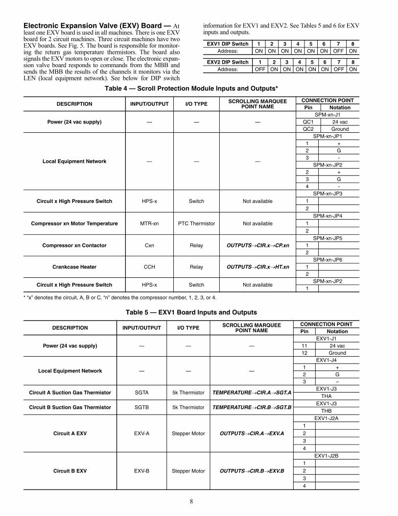
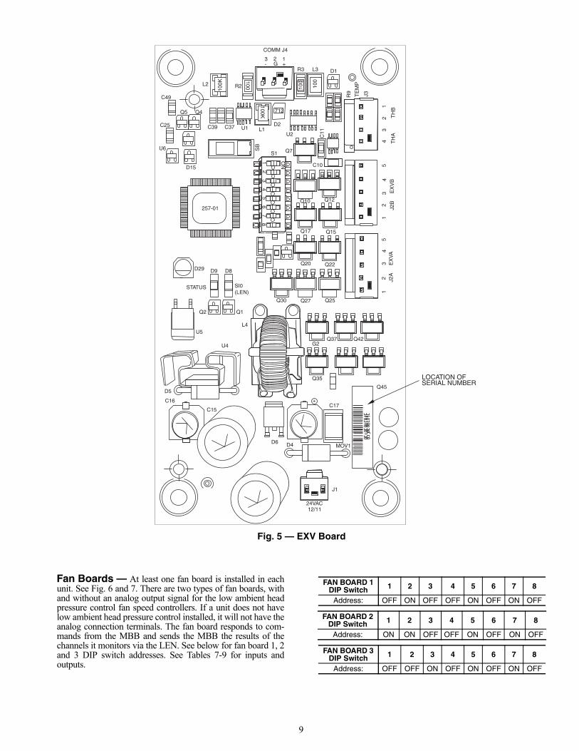
Electronic Expansion Valve (EXV) Board — Atleast one EXV board is used in all machines. There is one EXVboard for 2 circuit machines. Three circuit machines have twoEXV boards. See Fig. 5. The board is responsible for monitor-ing the return gas temperature thermistors. The board alsosignals the EXV motors to open or close. The electronic expan-sion valve board responds to commands from the MBB andsends the MBB the results of the channels it monitors via theLEN (local equipment network). See below for DIP switch
information for EXV1 and EXV2. See Tables 5 and 6 for EXVinputs and outputs.
Table 4 — Scroll Protection Module Inputs and Outputs*
* “x” denotes the circuit, A, B or C. “n” denotes the compressor number, 1, 2, 3, or 4.
Table 5 — EXV1 Board Inputs and Outputs
EXV1 DIP Switch 1 2 3 4 5 6 7 8Address: ON ON ON ON ON ON OFF ON
EXV2 DIP Switch 1 2 3 4 5 6 7 8Address: OFF ON ON ON ON ON OFF ON
DESCRIPTION INPUT/OUTPUT I/O TYPE SCROLLING MARQUEEPOINT NAME
CONNECTION POINTPin Notation
Power (24 vac supply) — — —SPM-xn-J1
QC1 24 vacQC2 Ground
Local Equipment Network — — —
SPM-xn-JP11 +2 G3 -
SPM-xn-JP22 +3 G4 -
Circuit x High Pressure Switch HPS-x Switch Not available
SPM-xn-JP31
2
Compressor xn Motor Temperature MTR-xn PTC Thermistor Not available
SPM-xn-JP41
2
Compressor xn Contactor Cxn Relay OUTPUTSCIR.xCP.xnSPM-xn-JP5
12
Crankcase Heater CCH Relay OUTPUTSCIR.xHT.xnSPM-xn-JP6
12
Circuit x High Pressure Switch HPS-x Switch Not availableSPM-xn-JP2
1
DESCRIPTION INPUT/OUTPUT I/O TYPE SCROLLING MARQUEEPOINT NAME
CONNECTION POINTPin Notation
Power (24 vac supply) — — —EXV1-J1
11 24 vac12 Ground
Local Equipment Network — — —
EXV1-J41 +2 G3 –
Circuit A Suction Gas Thermistor SGTA 5k Thermistor TEMPERATURECIR.ASGT.AEXV1-J3
THA
Circuit B Suction Gas Thermistor SGTB 5k Thermistor TEMPERATURECIR.BSGT.BEXV1-J3
THB
Circuit A EXV EXV-A Stepper Motor OUTPUTSCIR.AEXV.A
EXV1-J2A1
2
3
4
Circuit B EXV EXV-B Stepper Motor OUTPUTSCIR.BEXV.B
EXV1-J2B1
2
3
4
9
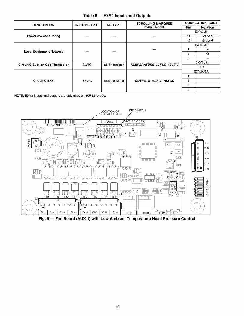
Fan Boards — At least one fan board is installed in eachunit. See Fig. 6 and 7. There are two types of fan boards, withand without an analog output signal for the low ambient headpressure control fan speed controllers. If a unit does not havelow ambient head pressure control installed, it will not have theanalog connection terminals. The fan board responds to com-mands from the MBB and sends the MBB the results of thechannels it monitors via the LEN. See below for fan board 1, 2and 3 DIP switch addresses. See Tables 7-9 for inputs andoutputs.
12
34
56
78
ON
100 100
257-01
712
100K
100K
100
12
34
5
3 2 1- G +
J3
12
34
5J2
A
EX
VA
J2B
E
XV
B
24VAC
STATUS
MOV1
LOCATION OFSERIAL NUMBER
43
21
TH
AT
HB
D4D6
J1
C15
C16
D5
U5
Q2 Q1
L4
U4
12/11
C17+
Q45
Q42Q37G2
Q35
Q25Q27Q30
Q20 Q22
Q17 Q15
Q12Q10
C10
Q7S1
C11U2
D2L1U1C37C39
SB
D15
U6
C25
C49
Q4Q5
L2 R2
R3 L3 D1
R9 TE
MP
D29 D9 D8
SI0(LEN)
COMM J4
Fig. 5 — EXV Board
FAN BOARD 1 DIP Switch 1 2 3 4 5 6 7 8
Address: OFF ON OFF OFF ON OFF ON OFF
FAN BOARD 2 DIP Switch 1 2 3 4 5 6 7 8
Address: ON ON OFF OFF ON OFF ON OFF
FAN BOARD 3 DIP Switch 1 2 3 4 5 6 7 8
Address: OFF OFF ON OFF ON OFF ON OFF
10
Table 6 — EXV2 Inputs and Outputs
NOTE: EXV2 inputs and outputs are only used on 30RB210-300.
DESCRIPTION INPUT/OUTPUT I/O TYPE SCROLLING MARQUEEPOINT NAME
CONNECTION POINTPin Notation
Power (24 vac supply) — — —EXV2-J1
11 24 vac12 Ground
Local Equipment Network — ——
EXV2-J41 +2 G3 –
Circuit C Suction Gas Thermistor SGTC 5k Thermistor TEMPERATURECIR.CSGT.CEXV2J3
THA
Circuit C EXV EXV-C Stepper Motor OUTPUTSCIR.CEXV.C
EXV2-J2A1
2
3
4
1 2 3 4 5 6 7 8
ON
100K 100K
100K
CH1 CH2 CH3 CH4 CH5 CH6 CH7 CH8
TR1 TR2 TR3 TR4 TR5 TR6 TR7 TR8
STATUS SIO (LEN)
LOCATION OFSERIAL NUMBER
24 VA
C
CH
13C
H14
J9
J1CH9 CH10 CH11 CH12
JP2
C61 CH13
D12 JP1
L3
L5
U21
L2
D6
D5Q5
Y1
D7
D8
S1
D3
U1
Q1
U5 U
6 U7
U8
U9 Q10
Q11
U10
J4
J3J2
U4
U2
Q12
Q60
3
2
1–
G
+
3
2
1–
G
+
DIP SWITCH
Fig. 6 — Fan Board (AUX 1) with Low Ambient Temperature Head Pressure Control

11
Table 7 — Fan Board 1 (AUX1, AUX2) Outputs*
*Fan boards 1 and 2 will use the AUX1 board when the low ambient temperature head pressure control option is installed.†Supplied on AUX1 board onlyNOTE: Fan Board 1 is used on 30RB060-390.
DESCRIPTION INPUT/OUTPUT I/O TYPE SCROLLING MARQUEEPOINT NAME
CONNECTION POINTPin Notation
Power (24 vac supply) — — —FB1-J1
11 24 vac12 Ground
Local Equipment Network — — —
FB1-J9+G-+G-
Circuit A Low AmbientTemperature Head Pressure
Control Speed SignalMM-A† 0-10 VDC OUTPUTSCIR.ASPD.A
FB1-CH9+-
Circuit B Low Ambient TemperatureHead Pressure Control Speed Signal
(sizes 060-150, 210-250)MM-B† 0-10 VDC OUTPUTSCIR.BSPD.B
FB1-CH10+
-
Outdoor Fan Motor 1 OFM1 TRIAC
FB1-J2-CH1(sizes 060-110)
FB1-J2-CH2(sizes 120-150, 210-250)
FB1-J2-CH3(sizes 160-190, 275, 300,
Duplex sizes 315-390)
Outdoor Fan Motor 2 OFM2 TRIAC
FB1-J2-CH2(sizes 060-110)
FB1-J2-CH3(sizes 120-150, 210-250)
FB1-J2-CH4(sizes 160-190, 275, 300,
Duplex sizes 315-390)
Outdoor Fan Motor 3 OFM3 TRIAC
FB1-J2-CH3(sizes 060,070,090-110)
FB1-J3-CH5(size 080)
FB1-J2-CH1(sizes 120-150, 210-250)
FB1-J2-CH2(sizes 160-190, 275, 300,
Duplex sizes 315-390)
Outdoor Fan Motor 4 OFM4 TRIAC
FB1-J2-CH4(sizes 060,070,130,
150,210-250)FB1-J3-CH6
(size 080)FB1-J3-CH7
(sizes 090-110)FB1-J3-CH5
(sizes 160-190, 275-300, Duplex sizes 315-390)
Outdoor Fan Motor 5 OFM5 TRIAC
FB1-J3-CH5(sizes 090-110)
FB1-J3-CH6(sizes 120-150, 210-250)
FB1-J2-CH1(sizes 160-190, 275-300,
Duplex sizes 315-390)
Outdoor Fan Motor 6 OFM6 TRIAC
FB1-J3-CH6(sizes 090-110,
160-190, 275-300,Duplex sizes 315-390)
FB1-J3-CH7(sizes 120-150, 210-250)
Outdoor Fan Motor 7 OFM7 TRIAC FB1-J3-CH5(sizes 120-150, 210-250)
Outdoor Fan Motor 8 OFM8 TRIAC FB1-J3-CH8(sizes 120-150, 210-250)

12
Table 8 — Fan Board 2 (AUX1, AUX2) Outputs*
*Fan boards 1 and 2 will use the AUX1 board when the low ambient temperature head pressure control option is installed.†Output only on units with low ambient temperature head pressure control installed (AUX1).NOTE: Fan Board 2 used on 30RB160-190, 275-300, 315-390.
DESCRIPTION INPUT/OUTPUT I/O TYPE SCROLLING MARQUEEPOINT NAME
CONNECTION POINTPin Notation
Power (24 vac supply) — — —FB2-J1
11 24 vac12 Ground
Local Equipment Network — — —
FB2-J9+G-+G-
Circuit B Low Ambient Temperature Head Pressure Control
Speed Signal(sizes 160-190, 275-300, 315-400)
MM-B† 0-10 VDC OUTPUTSCIR.BSPD.BFB2-CH9
+
-
Outdoor Fan Motor 7 OFM7† TRIAC
FB2-J2-CH2(sizes 160, 170, 315-345, 360B)
FB2-J2-CH3(sizes 190, 275, 300, 360A, 390)
Outdoor Fan Motor 8 OFM8 TRIAC
FB2-J2-CH3(sizes 160, 170, 315-345, 360B)
FB2-J2-CH4(sizes 190, 275, 300, 360A, 390)
Outdoor Fan Motor 9 OFM9 TRIAC
FB2-J2-CH1(sizes 160, 170, 315-345, 360B)
FB2-J2-CH2(sizes 190, 275, 300, 360A, 390)
Outdoor Fan Motor 10 OFM10 TRIAC
FB2-J2-CH4(sizes 160, 170, 315-345, 360B)
FB2-J3-CH5(sizes 190, 275, 300, 360A, 390)
Outdoor Fan Motor 11 OFM11 TRIAC FB2-J2-CH1(sizes 190, 275-300, 360A, 390)
Outdoor Fan Motor 12 OFM12 TRIAC FB2-J3-CH6(sizes 190, 275-300, 360A, 390)
1 2 3 4 5 6 7 8
ON
100K 100K
100K
LOCATION OFSERIAL NUMBER
TR1 TR2 TR3 TR4 TR5 TR6 TR7 TR8
CH1 CH2 CH3 CH4 CH5 CH6 CH7 CH8
STATUS SIO (LEN)
24 VA
C
J1
J9
D4
U2
U5
Q2
Q7
Q3
U8
U9
Q9
Q10
Q11
Q12
Q13
J4
J3J2
S1
D7
Q5
Y1
D5
D6
L2
U6
U1
Q1
D3
C3
3
2
1–
G
+
3
2
1–
G
+
DIP SWITCH
Fig. 7 — Fan Board (AUX 2) without Low Ambient Temperature Head Pressure Control
13
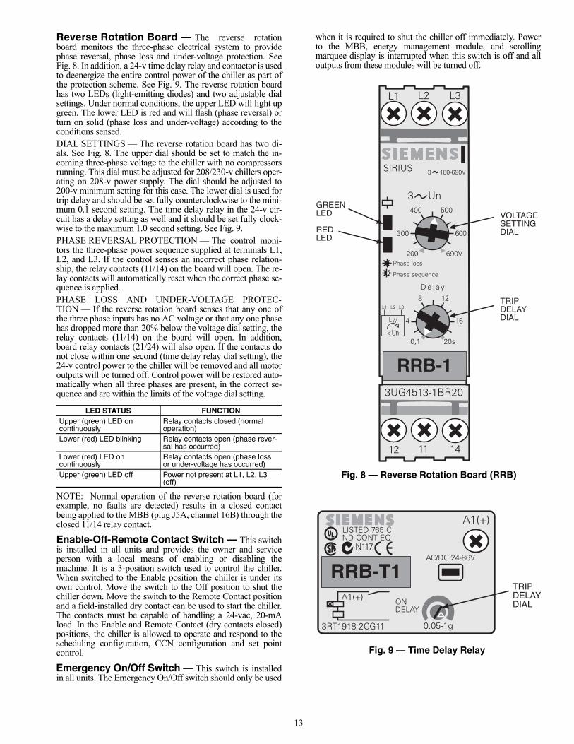
Reverse Rotation Board — The reverse rotationboard monitors the three-phase electrical system to providephase reversal, phase loss and under-voltage protection. SeeFig. 8. In addition, a 24-v time delay relay and contactor is usedto deenergize the entire control power of the chiller as part ofthe protection scheme. See Fig. 9. The reverse rotation boardhas two LEDs (light-emitting diodes) and two adjustable dialsettings. Under normal conditions, the upper LED will light upgreen. The lower LED is red and will flash (phase reversal) orturn on solid (phase loss and under-voltage) according to theconditions sensed.DIAL SETTINGS — The reverse rotation board has two di-als. See Fig. 8. The upper dial should be set to match the in-coming three-phase voltage to the chiller with no compressorsrunning. This dial must be adjusted for 208/230-v chillers oper-ating on 208-v power supply. The dial should be adjusted to200-v minimum setting for this case. The lower dial is used fortrip delay and should be set fully counterclockwise to the mini-mum 0.1 second setting. The time delay relay in the 24-v cir-cuit has a delay setting as well and it should be set fully clock-wise to the maximum 1.0 second setting. See Fig. 9.PHASE REVERSAL PROTECTION — The control moni-tors the three-phase power sequence supplied at terminals L1,L2, and L3. If the control senses an incorrect phase relation-ship, the relay contacts (11/14) on the board will open. The re-lay contacts will automatically reset when the correct phase se-quence is applied.PHASE LOSS AND UNDER-VOLTAGE PROTEC-TION — If the reverse rotation board senses that any one ofthe three phase inputs has no AC voltage or that any one phasehas dropped more than 20% below the voltage dial setting, therelay contacts (11/14) on the board will open. In addition,board relay contacts (21/24) will also open. If the contacts donot close within one second (time delay relay dial setting), the24-v control power to the chiller will be removed and all motoroutputs will be turned off. Control power will be restored auto-matically when all three phases are present, in the correct se-quence and are within the limits of the voltage dial setting.
NOTE: Normal operation of the reverse rotation board (forexample, no faults are detected) results in a closed contactbeing applied to the MBB (plug J5A, channel 16B) through theclosed 11/14 relay contact.
Enable-Off-Remote Contact Switch — This switchis installed in all units and provides the owner and serviceperson with a local means of enabling or disabling themachine. It is a 3-position switch used to control the chiller.When switched to the Enable position the chiller is under itsown control. Move the switch to the Off position to shut thechiller down. Move the switch to the Remote Contact positionand a field-installed dry contact can be used to start the chiller.The contacts must be capable of handling a 24-vac, 20-mAload. In the Enable and Remote Contact (dry contacts closed)positions, the chiller is allowed to operate and respond to thescheduling configuration, CCN configuration and set pointcontrol.
Emergency On/Off Switch — This switch is installedin all units. The Emergency On/Off switch should only be used
when it is required to shut the chiller off immediately. Powerto the MBB, energy management module, and scrollingmarquee display is interrupted when this switch is off and alloutputs from these modules will be turned off.
LED STATUS FUNCTIONUpper (green) LED oncontinuously
Relay contacts closed (normal operation)
Lower (red) LED blinking Relay contacts open (phase rever-sal has occurred)
Lower (red) LED oncontinuously
Relay contacts open (phase loss or under-voltage has occurred)
Upper (green) LED off Power not present at L1, L2, L3 (off)
Fig. 9 — Time Delay Relay
Fig. 8 — Reverse Rotation Board (RRB)
14
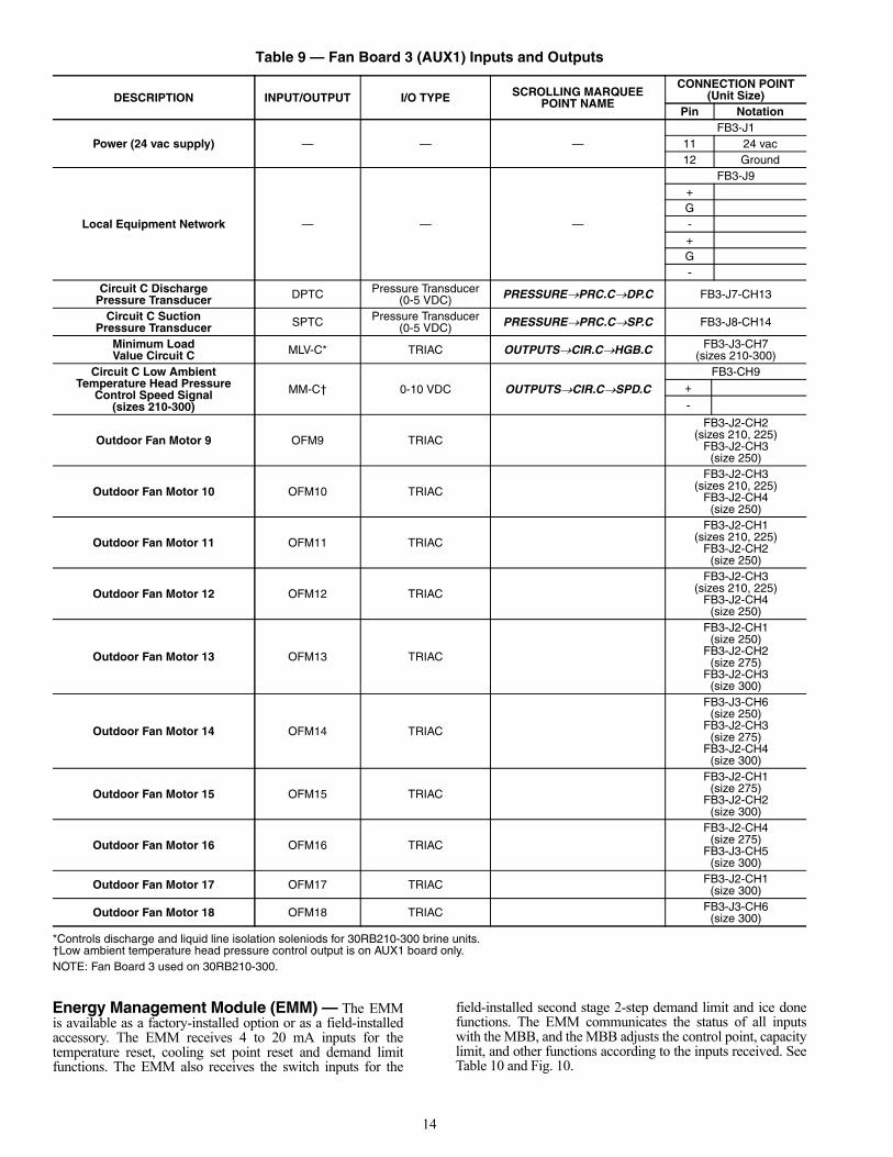
Table 9 — Fan Board 3 (AUX1) Inputs and Outputs
*Controls discharge and liquid line isolation soleniods for 30RB210-300 brine units.†Low ambient temperature head pressure control output is on AUX1 board only.NOTE: Fan Board 3 used on 30RB210-300.
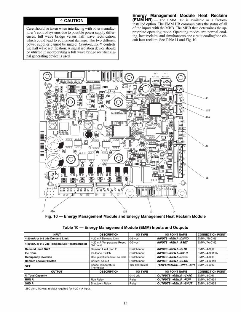
Energy Management Module (EMM) — The EMMis available as a factory-installed option or as a field-installedaccessory. The EMM receives 4 to 20 mA inputs for thetemperature reset, cooling set point reset and demand limitfunctions. The EMM also receives the switch inputs for the
field-installed second stage 2-step demand limit and ice donefunctions. The EMM communicates the status of all inputswith the MBB, and the MBB adjusts the control point, capacitylimit, and other functions according to the inputs received. SeeTable 10 and Fig. 10.
DESCRIPTION INPUT/OUTPUT I/O TYPE SCROLLING MARQUEEPOINT NAME
CONNECTION POINT(Unit Size)
Pin Notation
Power (24 vac supply) — — —FB3-J1
11 24 vac12 Ground
Local Equipment Network — — —
FB3-J9+G-+G-
Circuit C Discharge Pressure Transducer DPTC Pressure Transducer
(0-5 VDC) PRESSUREPRC.CDP.C FB3-J7-CH13
Circuit C Suction Pressure Transducer SPTC Pressure Transducer
(0-5 VDC) PRESSUREPRC.CSP.C FB3-J8-CH14
Minimum Load Value Circuit C MLV-C* TRIAC OUTPUTSCIR.CHGB.C FB3-J3-CH7
(sizes 210-300)Circuit C Low Ambient
Temperature Head Pressure Control Speed Signal
(sizes 210-300)
MM-C† 0-10 VDC OUTPUTSCIR.CSPD.C
FB3-CH9+
-
Outdoor Fan Motor 9 OFM9 TRIAC
FB3-J2-CH2(sizes 210, 225)
FB3-J2-CH3(size 250)
Outdoor Fan Motor 10 OFM10 TRIAC
FB3-J2-CH3(sizes 210, 225)
FB3-J2-CH4(size 250)
Outdoor Fan Motor 11 OFM11 TRIAC
FB3-J2-CH1(sizes 210, 225)
FB3-J2-CH2(size 250)
Outdoor Fan Motor 12 OFM12 TRIAC
FB3-J2-CH3(sizes 210, 225)
FB3-J2-CH4(size 250)
Outdoor Fan Motor 13 OFM13 TRIAC
FB3-J2-CH1(size 250)
FB3-J2-CH2(size 275)
FB3-J2-CH3(size 300)
Outdoor Fan Motor 14 OFM14 TRIAC
FB3-J3-CH6(size 250)
FB3-J2-CH3(size 275)
FB3-J2-CH4(size 300)
Outdoor Fan Motor 15 OFM15 TRIAC
FB3-J2-CH1(size 275)
FB3-J2-CH2(size 300)
Outdoor Fan Motor 16 OFM16 TRIAC
FB3-J2-CH4(size 275)
FB3-J3-CH5(size 300)
Outdoor Fan Motor 17 OFM17 TRIAC FB3-J2-CH1(size 300)
Outdoor Fan Motor 18 OFM18 TRIAC FB3-J3-CH6(size 300)
15
Energy Management Module Heat Reclaim(EMM HR) — The EMM HR is available as a factory-installed option. The EMM HR communicates the status of allof the inputs with the MBB. The MBB then determines the ap-propriate operating mode. Operating modes are: normal cool-ing, heat reclaim, and simultaneous one circuit cooling/one cir-cuit heat reclaim. See Table 11 and Fig. 10.
Table 10 — Energy Management Module (EMM) Inputs and Outputs
* 250 ohm, 1/2 watt resistor required for 4-20 mA input.
CAUTION
Care should be taken when interfacing with other manufac-turer’s control systems due to possible power supply differ-ences, full wave bridge versus half wave rectification,which could lead to equipment damage. The two differentpower supplies cannot be mixed. ComfortLink™ controlsuse half wave rectification. A signal isolation device shouldbe utilized if incorporating a full wave bridge rectifier sig-nal generating device is used.
INPUT DESCRIPTION I/O TYPE I/O POINT NAME CONNECTION POINT4-20 mA or 0-5 vdc Demand Limit 4-20 mA Demand Limit 0-5 vdc* INPUTSGEN.IDMND EMM-J7B-CH6
4-20 mA or 0-5 vdc Temperature Reset/Setpoint 4-20 mA Temperature Reset/ Set point
0-5 vdc* INPUTSGEN.IRSET EMM-J7A-CH5
Demand Limit SW2 Demand Limit Step 2 Switch Input INPUTSGEN.IDLS2 EMM-J4-CH9Ice Done Ice Done Switch Switch Input INPUTSGEN.IICE.D EMM-J4-CH11AOccupancy Override Occupied Schedule Override Switch Input INPUTSGEN.IOCCS EMM-J4-CH8Remote Lockout Switch Chiller Lockout Switch Input INPUTSGEN.IRLOC EMM-J4-CH10
SPT Space TemperatureThermistor
10k Thermistor TEMPERATUREUNITSPT EMM-J6-CH2
OUTPUT DESCRIPTION I/O TYPE I/O POINT NAME CONNECTION POINT% Total Capacity 0-10 vdc OUTPUTSGEN.OCATO EMM-J8-CH7RUN R Run Relay Relay OUTPUTSGEN.ORUN EMM-J3-CH24SHD R Shutdown Relay Relay OUTPUTSGEN.OSHUT EMM-J3-CH25
221221
221 221
100K
100K
100K
100K
100K
CH 17
CH 17
CH 16
CH
CH 18
CH 19
CH 20
CH 22
CH 21
CH 23
24 VA
C
12 11
CH
11
b C
H
12
CH
13
C
H
14
CH
15
C
H 1
CH
2 C
H 3
CH
4 C
H 5
C
H 6
C
H 7
SIO LEN
+ G - + G -
SIO LEN
J8
J7B
J7A
J6
J5
J4 J3 J2B J2AJ1
Fig. 10 — Energy Management Module and Energy Management Heat Reclaim Module
a30-4465

16
Table 11 — Energy Management Module Heat Reclaim (EMM HR) Inputs and Outputs
Local Equipment Network — Information is trans-mitted between modules via a 3-wire communication bus orLEN (Local Equipment Network). External connection to theLEN bus is made at TB3.
Board Addresses — All boards (except the main baseboard and the energy management module) have 8-positionDIP switches. Addresses for all boards are listed with the input/output tables for each board.
Control Module CommunicationRED LED — Proper operation of the control boards can bevisually checked by looking at the red status LEDs (light-emitting diodes). When operating correctly, the red statusLEDs will blink in unison at a rate of once every 2 seconds. Ifthe red LEDs are not blink in unison, verify that correct poweris being supplied to all modules. Be sure that the main baseboard (MBB) is supplied with the current software. If neces-sary, reload current software. If the problem still persists,replace the MBB. A red LED that is lit continuously or blink-ing at a rate of once per second or faster indicates that the boardshould be replaced.GREEN LED — All boards have a green LEN (SIO) LEDwhich should be blinking whenever power is on. If the LEDsare not blinking as described check LEN connections forpotential communication errors at the board connectors. SeeInput/Output Tables for LEN connector designations. A 3-wirebus accomplishes communication between modules. These
3 wires run in parallel from module to module. The J9A con-nector on the MBB provides communication directly to thescrolling marquee display or the Navigator™ display module.YELLOW LED — The MBB has one yellow LED. TheCarrier Comfort Network® (CCN) LED will blink during timesof network communication.
Carrier Comfort Network (CCN) Interface — All30RB units can be connected to the CCN, if desired. The com-munication bus wiring is a shielded, 3-conductor cable withdrain wire and is field supplied and installed. The system ele-ments are connected to the communication bus in a daisy chainarrangement. The positive pin of each system element commu-nication connector must be wired to the positive pins of thesystem elements on either side of it, that is also required for thenegative and signal ground pins of each system element. Wir-ing connections for CCN should be made at TB3. Consult theCCN Contractor’s Manual for further information. See Fig. 11.NOTE: Conductors and drain wire must be 20 AWG (Ameri-can Wire Gage) minimum stranded, tinned copper. Individualconductors must be insulated with PVC, PVC/nylon, vinyl,Teflon, or polyethylene. An aluminum/polyester 100% foilshield and an outer jacket of PVC, PVC/nylon, chrome vinyl,or Teflon with a minimum operating temperature range of–20 C to 60 C is required. See Table 12 for recommended wiremanufacturers and part numbers.
INPUT DESCRIPTION I/O TYPE I/O POINT NAME CONNECTION POINTPD.B Circuit B Pumpdown Pressure Transducer Pressure Transducer PRESSURECIR.BPD.B EMM-J8-CH6PD.A Circuit A Pumpdown Pressure Transducer Pressure Transducer PRESSURECIR.APD.A EMM-J8-CH5
HRS.B Circuit B Liquid Subcooling — TEMPERATURECIR.BHRS.B —HRS.A Circuit A Liquid Subcooling — TEMPERATURECIR.AHRS.A —HRT.B Circuit B Liquid Temperature Temperature TEMPERATURECIR.BHRT.B EMM-J5-CH4HRT.A Circuit A Liquid Temperature Temperature TEMPERATURECIR.AHRT.A EMM-J5-CH3HEWT Heat Reclaim Entering Fluid Temperature TEMPERATUREUNITHEWT EMM-J5-CH2HLWT Heat Reclaim Leaving Fluid Temperature TEMPERATUREUNITHLWT EMM-J5-CH1C.FLO Condenser Flow Switch Status Switch INPUTSGEN.IC.FLO EMM-J5-CH15
— Power (24 vac supply) — — EMM-J1-CH11,12— Local Equipment Network — — EMM-J9
OUTPUT DESCRIPTION I/O TYPE I/O POINT NAME CONNECTION POINTCondenser 0-10 VDC Water Valve Output 0-10 VDC — EMM-J8-CH7
CND.P Heat Reclaim Condenser Pump Status Contactor OUTPUTSGEN.OCND.P EMM-J2-CH16CN.HT Heat Reclaim Condenser Heater Contactor OUTPUTSGEN.OCN.HT EMM-J2-CH17HR2.A Circuit A, Leaving Air-Cooled Cond Solenoid Contactor OUTPUTSCIR.AHR2.A EMM-J2-CH18HR2.B Circuit B, Leaving Air-Cooled Cond Solenoid Contactor OUTPUTSCIR.BHR2.B EMM-J2-CH19HR3.A Circuit A, Entering Water-Cooled Cond Solenoid Contactor OUTPUTSCIR.AHR3.A EMM-J2-CH20HR3.B Circuit B, Entering Water-Cooled Cond Solenoid Contactor OUTPUTSCIR.BHR3.B EMM-J2-CH21HR4.A Circuit A, Leaving Water-Cooled Cond Solenoid Contactor OUTPUTSCIR.AHR4.A EMM-J2-CH22HR4.B Circuit B, Leaving Water-Cooled Cond Solenoid Contactor OUTPUTSCIR.BHR4.B EMM-J2-CH23HR1.A Circuit A, Entering Air-Cooled Cond Solenoid Contactor OUTPUTSCIR.AHR1.A EMM-J3-CH24HR1.B Circuit B, Entering Air-Cooled Cond Solenoid Contactor OUTPUTSCIR.BHR1.B EMM-J3-CH25
Fig. 11 — ComfortLink™ CCN Communication Wiring
17
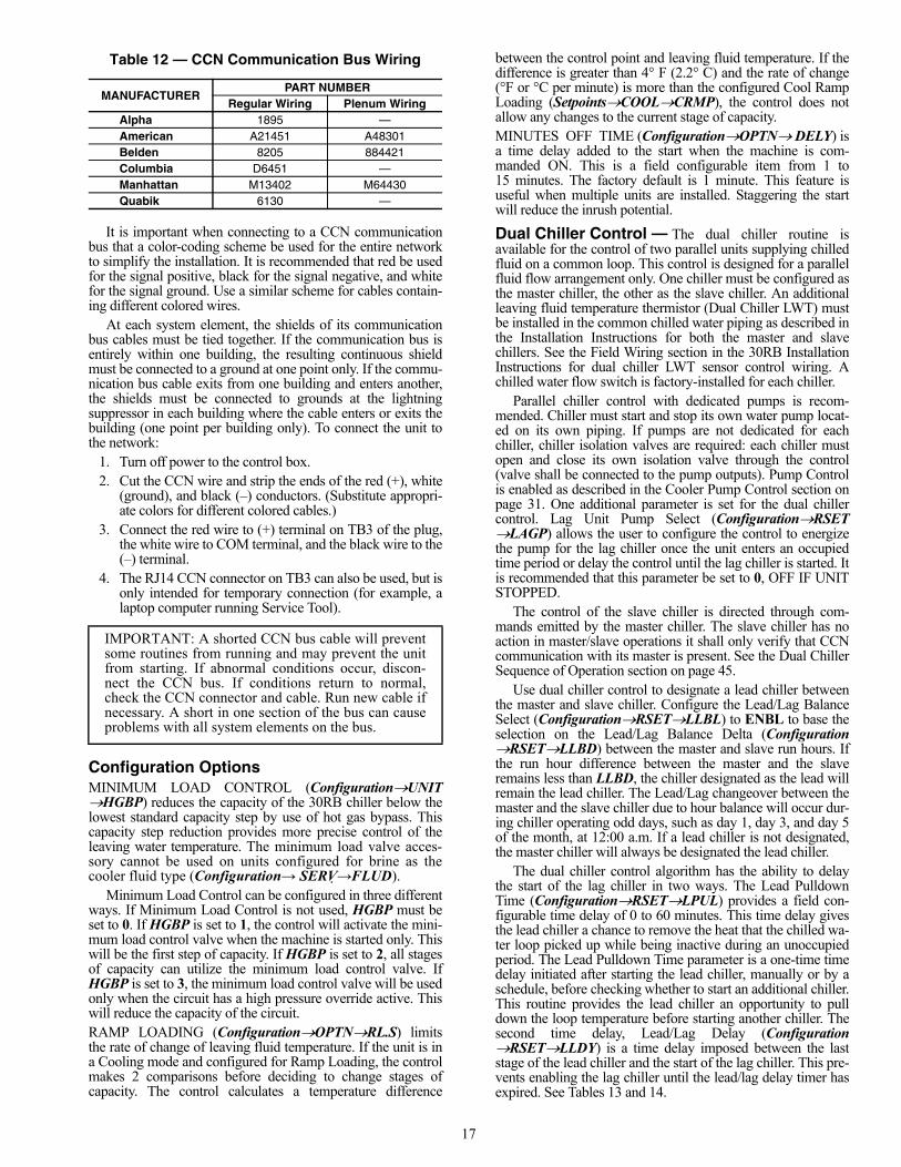
Table 12 — CCN Communication Bus Wiring
It is important when connecting to a CCN communicationbus that a color-coding scheme be used for the entire networkto simplify the installation. It is recommended that red be usedfor the signal positive, black for the signal negative, and whitefor the signal ground. Use a similar scheme for cables contain-ing different colored wires.
At each system element, the shields of its communicationbus cables must be tied together. If the communication bus isentirely within one building, the resulting continuous shieldmust be connected to a ground at one point only. If the commu-nication bus cable exits from one building and enters another,the shields must be connected to grounds at the lightningsuppressor in each building where the cable enters or exits thebuilding (one point per building only). To connect the unit tothe network:
1. Turn off power to the control box.2. Cut the CCN wire and strip the ends of the red (+), white
(ground), and black (–) conductors. (Substitute appropri-ate colors for different colored cables.)
3. Connect the red wire to (+) terminal on TB3 of the plug,the white wire to COM terminal, and the black wire to the(–) terminal.
4. The RJ14 CCN connector on TB3 can also be used, but isonly intended for temporary connection (for example, alaptop computer running Service Tool).
Configuration OptionsMINIMUM LOAD CONTROL (ConfigurationUNITHGBP) reduces the capacity of the 30RB chiller below thelowest standard capacity step by use of hot gas bypass. Thiscapacity step reduction provides more precise control of theleaving water temperature. The minimum load valve acces-sory cannot be used on units configured for brine as thecooler fluid type (Configuration→ SERV →FLUD).
Minimum Load Control can be configured in three differentways. If Minimum Load Control is not used, HGBP must beset to 0. If HGBP is set to 1, the control will activate the mini-mum load control valve when the machine is started only. Thiswill be the first step of capacity. If HGBP is set to 2, all stagesof capacity can utilize the minimum load control valve. IfHGBP is set to 3, the minimum load control valve will be usedonly when the circuit has a high pressure override active. Thiswill reduce the capacity of the circuit.RAMP LOADING (ConfigurationOPTNRL.S) limitsthe rate of change of leaving fluid temperature. If the unit is ina Cooling mode and configured for Ramp Loading, the controlmakes 2 comparisons before deciding to change stages ofcapacity. The control calculates a temperature difference
between the control point and leaving fluid temperature. If thedifference is greater than 4° F (2.2° C) and the rate of change(°F or °C per minute) is more than the configured Cool RampLoading (SetpointsCOOLCRMP), the control does notallow any changes to the current stage of capacity.MINUTES OFF TIME (ConfigurationOPTNDELY) isa time delay added to the start when the machine is com-manded ON. This is a field configurable item from 1 to15 minutes. The factory default is 1 minute. This feature isuseful when multiple units are installed. Staggering the startwill reduce the inrush potential.
Dual Chiller Control — The dual chiller routine isavailable for the control of two parallel units supplying chilledfluid on a common loop. This control is designed for a parallelfluid flow arrangement only. One chiller must be configured asthe master chiller, the other as the slave chiller. An additionalleaving fluid temperature thermistor (Dual Chiller LWT) mustbe installed in the common chilled water piping as described inthe Installation Instructions for both the master and slavechillers. See the Field Wiring section in the 30RB InstallationInstructions for dual chiller LWT sensor control wiring. Achilled water flow switch is factory-installed for each chiller.
Parallel chiller control with dedicated pumps is recom-mended. Chiller must start and stop its own water pump locat-ed on its own piping. If pumps are not dedicated for eachchiller, chiller isolation valves are required: each chiller mustopen and close its own isolation valve through the control(valve shall be connected to the pump outputs). Pump Controlis enabled as described in the Cooler Pump Control section onpage 31. One additional parameter is set for the dual chillercontrol. Lag Unit Pump Select (ConfigurationRSETLAGP) allows the user to configure the control to energizethe pump for the lag chiller once the unit enters an occupiedtime period or delay the control until the lag chiller is started. Itis recommended that this parameter be set to 0, OFF IF UNITSTOPPED.
The control of the slave chiller is directed through com-mands emitted by the master chiller. The slave chiller has noaction in master/slave operations it shall only verify that CCNcommunication with its master is present. See the Dual ChillerSequence of Operation section on page 45.
Use dual chiller control to designate a lead chiller betweenthe master and slave chiller. Configure the Lead/Lag BalanceSelect (ConfigurationRSETLLBL) to ENBL to base theselection on the Lead/Lag Balance Delta (ConfigurationRSETLLBD) between the master and slave run hours. Ifthe run hour difference between the master and the slaveremains less than LLBD, the chiller designated as the lead willremain the lead chiller. The Lead/Lag changeover between themaster and the slave chiller due to hour balance will occur dur-ing chiller operating odd days, such as day 1, day 3, and day 5of the month, at 12:00 a.m. If a lead chiller is not designated,the master chiller will always be designated the lead chiller.
The dual chiller control algorithm has the ability to delaythe start of the lag chiller in two ways. The Lead PulldownTime (ConfigurationRSETLPUL) provides a field con-figurable time delay of 0 to 60 minutes. This time delay givesthe lead chiller a chance to remove the heat that the chilled wa-ter loop picked up while being inactive during an unoccupiedperiod. The Lead Pulldown Time parameter is a one-time timedelay initiated after starting the lead chiller, manually or by aschedule, before checking whether to start an additional chiller.This routine provides the lead chiller an opportunity to pulldown the loop temperature before starting another chiller. Thesecond time delay, Lead/Lag Delay (ConfigurationRSETLLDY) is a time delay imposed between the laststage of the lead chiller and the start of the lag chiller. This pre-vents enabling the lag chiller until the lead/lag delay timer hasexpired. See Tables 13 and 14.
MANUFACTURERPART NUMBER
Regular Wiring Plenum WiringAlpha 1895 —American A21451 A48301Belden 8205 884421Columbia D6451 —Manhattan M13402 M64430Quabik 6130 —
IMPORTANT: A shorted CCN bus cable will preventsome routines from running and may prevent the unitfrom starting. If abnormal conditions occur, discon-nect the CCN bus. If conditions return to normal,check the CCN connector and cable. Run new cable ifnecessary. A short in one section of the bus can causeproblems with all system elements on the bus.

18
Table 13 — Configuring the Master Chiller
NOTE: Bold values indicate sub-mode level.
MODE KEYPAD ENTRY DISPLAY ITEM EXPANSION COMMENTCONFIGURATION DISP
UNIT
SERV
OPTN
CCNA CCN Address Confirm address of chiller. The master and slave chiller must have different addresses.
1 Factory default address is 1.
CCNA
CCNB CCN Bus Number Confirm the bus number of the chiller. The master and slave chiller must be on the same bus.
0 Factory default is 0.
CCNB
OPTN
RSET Reset Cool and Heat Tmp
CRST Cooling Reset Type
x 5 MSSL Master/Slave Select
0 Disable
0 Disable Flashing to indicate Edit mode. May require Password.
1 Master Use up arrows to change value to 1.
1 Accepts the change.
MSSL
SLVA Slave Address
1
1 Flashing to indicate Edit mode.
2 Use up arrows to change value to 2. This address must match the address of the slave chiller.
2 Accepts the change.
SLVA
LLBL Lead/Lag Balance Select
ENBL Factory Default is ENBL
LLBL
LLBD Lead/Lag Balance Delta
168 Factory Default is 168.
LLBD
LLDY Lead/Lag Start Delay
10 Factory Default is 10.
LLDY
LAGP Lag Unit Pump Select
0 Off if U Stp Factory Default is 0, Off if unit is stopped. Master and slave chiller must be configured to the same value.
LAGP
LPUL Lead Pulldown Time
0 Factory Default is 0.
At mode level.
OPERATINGMODES OPER Operating Control Type
0 Switch Control Master chiller should be configured for job requirements, Switch Control, Time Schedule, or CCN.
At mode level.
ENTER
ENTER
ENTER
ESCAPE
ENTER
ESCAPE
ESCAPE
ENTER
ENTER
ENTER
ENTER
ESCAPE
ENTER
ENTER
ENTER
ESCAPE
ENTER
ESCAPE
ENTER
ESCAPE
ENTER
ESCAPE
ENTER
ESCAPE
ENTER
ESCAPE
ESCAPE
ENTER
ENTER
ESCAPE
19
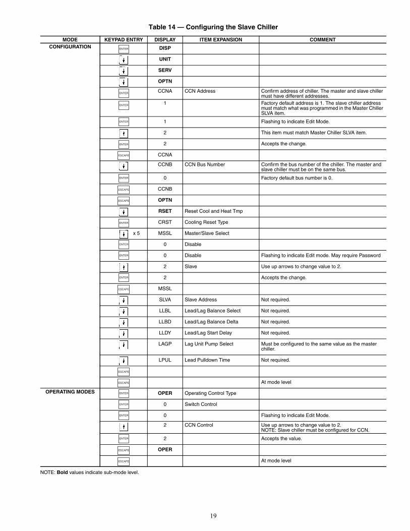
Table 14 — Configuring the Slave Chiller
NOTE: Bold values indicate sub-mode level.
MODE KEYPAD ENTRY DISPLAY ITEM EXPANSION COMMENTCONFIGURATION DISP
UNIT
SERV
OPTN
CCNA CCN Address Confirm address of chiller. The master and slave chiller must have different addresses.
1 Factory default address is 1. The slave chiller address must match what was programmed in the Master Chiller SLVA item.
1 Flashing to indicate Edit Mode.
2 This item must match Master Chiller SLVA item.
2 Accepts the change.
CCNA
CCNB CCN Bus Number Confirm the bus number of the chiller. The master and slave chiller must be on the same bus.
0 Factory default bus number is 0.
CCNB
OPTN
RSET Reset Cool and Heat Tmp
CRST Cooling Reset Type
x 5 MSSL Master/Slave Select
0 Disable
0 Disable Flashing to indicate Edit mode. May require Password
2 Slave Use up arrows to change value to 2.
2 Accepts the change.
MSSL
SLVA Slave Address Not required.
LLBL Lead/Lag Balance Select Not required.
LLBD Lead/Lag Balance Delta Not required.
LLDY Lead/Lag Start Delay Not required.
LAGP Lag Unit Pump Select Must be configured to the same value as the master chiller.
LPUL Lead Pulldown Time Not required.
At mode level
OPERATING MODES OPER Operating Control Type
0 Switch Control
0 Flashing to indicate Edit Mode.
2 CCN Control Use up arrows to change value to 2. NOTE: Slave chiller must be configured for CCN.
2 Accepts the value.
OPER
At mode level
ENTER
ENTER
ENTER
ENTER
ENTER
ESCAPE
ENTER
ESCAPE
ESCAPE
ENTER
ENTER
ENTER
ENTER
ESCAPE
ESCAPE
ESCAPE
ENTER
ENTER
ENTER
ENTER
ESCAPE
ESCAPE
20
The Lag Unit Pump Select configuration must be setconsistently. If pump control is NOT being used, set Con-figurationRSETLAGP to 1. If pump control IS beingused, set ConfigurationRSETLAGP to 0, which is thedefault value. This must be set in both the master and slavechillers, and it must be consistent in both.
Capacity Control — The control system cycles com-pressors and minimum load valve solenoids (if equipped) tomaintain the user-configured leaving chilled fluid temperatureset point. Entering fluid temperature is used by the main baseboard (MBB) to determine the temperature drop across thecooler and is used in determining the optimum time to add orsubtract capacity stages. Entering fluid temperature, spacetemperature (requires additional sensor), or outdoor-air temper-ature reset features can automatically reset the leaving chilledfluid temperature set point. It can also be reset from an external4 to 20-mA signal (requires energy management module).
The control has an automatic lead-lag feature built in forcircuit and compressor starts. If enabled, the control will deter-mine which circuit (ConfigurationOPTNLLCS=0) andcompressor to start to even the wear. The compressor wearfactor (combination of starts and run hours) is used to deter-mine which compressor starts.
Compressor Wear Factor = (Compressor Starts) + 0.1(Compressor Run Hours)
In this case, the circuit with the lowest average compressorwear factor (the average of the wear factors of all availablecompressors in the circuit) is the circuit that starts first. Thecompressor within the circuit with the lowest wear factor is thefirst to start. If the automatic lead-lag function for the circuit isnot enabled [ConfigurationOPTNLLCS=1 (Circuit Aleads), 2 (Circuit B leads), or 3 (Circuit C leads)], then the se-lected circuit will be the first to start. Again, the compressorwith the lowest wear factor within the circuit will be the first tostart. If Minimum Load Control is enabled (ConfigurationUNITHGBP=1), the valve will be operational only duringthe first stage of cooling.
Once the lead compressor has been started, the lag compres-sors will be determined by the wear factor and loadingsequence selected. If equal loading is selected, (Configura-tionOPTNLOAD=0), the circuit with the lowest averagewear factor for the available compressors will start next, withthe compressor with the lowest wear factor starting. The con-trol will attempt to keep all circuits at approximately the samenumber of compressors ON. For this option to function proper-ly, all circuits must have the same number of compressorsavailable. If a circuit compressor is not available due to analarm condition or demand limit, the capacity staging willchange to staged. If staged loading is selected, (Configura-tionOPTNLOAD=1), the started circuit will continue toturn on compressors according to the lowest wear factor untilall are on, then start the next circuit with the lowest averagewear factor. If Minimum Load Control is enabled for closecontrol (ConfigurationUNITHGBP=2), the valve will be
available at all stages for better temperature control. IfMinimum Load Control is enabled for high ambient control(ConfigurationUNITHGBP=3), the valve will be usedonly when a high pressure override is active for that circuit.
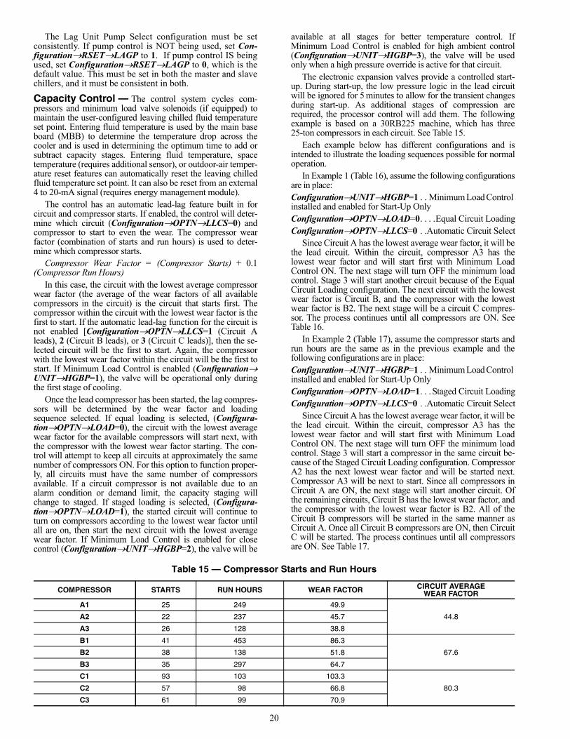
The electronic expansion valves provide a controlled start-up. During start-up, the low pressure logic in the lead circuitwill be ignored for 5 minutes to allow for the transient changesduring start-up. As additional stages of compression arerequired, the processor control will add them. The followingexample is based on a 30RB225 machine, which has three25-ton compressors in each circuit. See Table 15.
Each example below has different configurations and isintended to illustrate the loading sequences possible for normaloperation.
In Example 1 (Table 16), assume the following configurationsare in place:ConfigurationUNITHGBP=1 . . Minimum Load Control installed and enabled for Start-Up OnlyConfigurationOPTNLOAD=0. . . .Equal Circuit LoadingConfigurationOPTNLLCS=0 . .Automatic Circuit Select
Since Circuit A has the lowest average wear factor, it will bethe lead circuit. Within the circuit, compressor A3 has thelowest wear factor and will start first with Minimum LoadControl ON. The next stage will turn OFF the minimum loadcontrol. Stage 3 will start another circuit because of the EqualCircuit Loading configuration. The next circuit with the lowestwear factor is Circuit B, and the compressor with the lowestwear factor is B2. The next stage will be a circuit C compres-sor. The process continues until all compressors are ON. SeeTable 16.
In Example 2 (Table 17), assume the compressor starts andrun hours are the same as in the previous example and thefollowing configurations are in place:ConfigurationUNITHGBP=1 . . Minimum Load Control installed and enabled for Start-Up OnlyConfigurationOPTNLOAD=1. . . Staged Circuit LoadingConfigurationOPTNLLCS=0 . .Automatic Circuit Select
Since Circuit A has the lowest average wear factor, it will bethe lead circuit. Within the circuit, compressor A3 has thelowest wear factor and will start first with Minimum LoadControl ON. The next stage will turn OFF the minimum loadcontrol. Stage 3 will start a compressor in the same circuit be-cause of the Staged Circuit Loading configuration. CompressorA2 has the next lowest wear factor and will be started next.Compressor A3 will be next to start. Since all compressors inCircuit A are ON, the next stage will start another circuit. Ofthe remaining circuits, Circuit B has the lowest wear factor, andthe compressor with the lowest wear factor is B2. All of theCircuit B compressors will be started in the same manner asCircuit A. Once all Circuit B compressors are ON, then CircuitC will be started. The process continues until all compressorsare ON. See Table 17.
Table 15 — Compressor Starts and Run Hours
COMPRESSOR STARTS RUN HOURS WEAR FACTOR CIRCUIT AVERAGEWEAR FACTOR
A1 25 249 49.9
44.8A2 22 237 45.7
A3 26 128 38.8
B1 41 453 86.3
67.6B2 38 138 51.8
B3 35 297 64.7
C1 93 103 103.3
80.3C2 57 98 66.8
C3 61 99 70.9

21
Table 16 — Compressor Stages and Circuit Cycling, Example 1
LEGEND NOTES:1. Total Cap. (Total Unit Capacity) and Cir. Cap. (Circuit Capacity)
are approximate percentage values.2. Example is to determine minimum load control, staged circuit
loading, and automatic circuit select.
Table 17 — Compressor Stage and Circuit Cycling, Example 2
LEGEND NOTES:1. Total Cap. (Total Unit Capacity) and Cir. Cap. (Circuit Capacity)
are approximate percentage values.2. Example is to determine minimum load control, staged circuit
loading, and automatic circuit select.
In Example 3 (Table 18), assume the following configurationsare in place:ConfigurationUNITHGBP=1 . . Minimum Load Control installed and enabled for Start-Up OnlyConfigurationOPTNLOAD=0 . . .Equal Circuit LoadingConfigurationOPTNLLCS=2 . . . . . . . . . Circuit B Leads
Since Circuit B has been selected, it will be the lead circuit.Within the circuit, compressor B2 has the lowest wear factorand will start first with Minimum Load Control ON. The nextstage will turn OFF the minimum load control. Stage 3 willstart another circuit because of the Equal Circuit Loadingconfiguration. Comparing Circuit A and C, the circuit with thelowest average wear factor is Circuit A, and the compressorwith the lowest wear factor is A3. The next stage will be acircuit C compressor. The process continues until all compres-sors are ON. See Table 18.
In Example 4 (Table 19), assume the compressor starts andrun hours are the same as in the first example and the followingconfigurations are in place:ConfigurationUNITHGBP=1 . . Minimum Load Control installed and enabled for Start-Up OnlyConfigurationOPTNLOAD=1 . . Staged Circuit LoadingConfigurationOPTNLLCS=3 . . . . . . . . . Circuit C Leads
Since Circuit C has been selected, it will be the lead circuit.Within the circuit, compressor C2 has the lowest wear factorand will start first with Minimum Load Control ON. The nextstage will turn OFF the minimum load control. Stage 3 willstart a compressor in the same circuit because of the StagedCircuit Loading configuration. Compressor C3 has the nextlowest wear factor and will be started next. Compressor C1will be next to start. Since all compressors in Circuit C are ON,the next stage will start another circuit. Of the remaining cir-cuits, Circuit A has the lowest wear factor, and the compressorwith the lowest wear factor is A3. All of the Circuit A com-pressors will be started in the same manner as Circuit C. Onceall Circuit A compressors are ON, then Circuit B will be start-ed. The process continues until all compressors are ON. SeeTable 19.
If the circuit capacity is to be reduced, the compressor withthe highest wear factor will be shut off first (in most cases).With Equal Circuit Loading, stages will be removed from eachcircuit, following the same criteria used in the loadingsequence, but in the opposite order. Shown in Table 19 basedon the current wear factor in the opposite to the loadingsequence shown above, the compressor with the highest wearfactor will be removed first. When Staged Circuit Loading isselected, the capacity from the last lag circuit will be removedfirst.
STAGE TOTALCAP.
CIRCUIT A CIRCUIT B CIRCUIT CCir.
Cap. MLC A1 A2 A3 Cir. Cap. MLC B1 B2 B3 Cir.
Cap. MLC C1 C2 C3
0 0 0 0 01 8 24 X X 0 02 11 33 X 0 03 22 33 X 33 X 04 33 33 X 33 X 33 X5 44 66 X X 33 X 33 X6 55 66 X X 66 X X 33 X7 66 66 X X 66 X X 66 X X8 77 100 X X X 66 X X 66 X X9 88 100 X X X 100 X X X 66 X X
10 100 100 X X X 100 X X X 100 X X X
MLC — Minimum Load Control
STAGE TOTALCAP.
CIRCUIT A CIRCUIT B CIRCUIT CCir.
Cap. MLC A1 A2 A3 Cir. Cap. MLC B1 B2 B3 Cir.
Cap. MLC C1 C2 C3
0 0 0 0 01 8 24 X X 0 02 11 33 X 0 03 22 66 X X 0 04 33 100 X X X 0 05 44 100 X X X 33 X 06 55 100 X X X 66 X X 07 66 100 X X X 100 X X X 08 77 100 X X X 100 X X X 33 X9 88 100 X X X 100 X X X 66 X X
10 100 100 X X X 100 X X X 100 X X X
MLC — Minimum Load Control

22
Table 18 — Compressor Stage and Circuit Cycling, Example 3
LEGEND NOTES:1. Total Cap. (Total Unit Capacity) and Cir. Cap. (Circuit Capacity)
are approximate percentage values.2. Example is to determine minimum load control, staged circuit
loading, and automatic circuit select.
Table 19 — Compressor Stage and Circuit Cycling, Example 4
LEGEND NOTES:1. Total Cap. (Total Unit Capacity) and Cir. Cap. (Circuit Capacity)
are approximate percentage values.2. Example is to determine minimum load control, staged circuit
loading, and automatic circuit select.
The capacity control algorithm runs every 30 seconds. Thealgorithm attempts to maintain the Control Point at the desiredset point. Each time it runs, the control reads the entering andleaving fluid temperatures. The control determines the rate atwhich conditions are changing and calculates 2 variables basedon these conditions. Next, a capacity ratio (SM2) is calculatedusing the 2 variables to determine whether or not to make anychanges to the current stages of capacity. This ratio valueranges from –100 to +100%. If the next stage of capacity is acompressor, the control starts (stops) a compressor when theratio reaches +100% (–100%). If the next stage of capacityis the Minimum Load Control, the control energizes (deener-gizes) the Minimum Load Control when the ratio reaches+60% (–60%). If installed, the minimum load valve solenoidwill be energized with the first stage of capacity. The controlwill also use the minimum load valve solenoid as the last stageof capacity before turning off the last compressor. If the closecontrol feature (ConfigurationUNITHGBP=2) is en-abled the control will use the minimum load valve solenoidwhenever possible to fine tune leaving fluid temperature con-trol. A delay of 90 seconds occurs after each capacity stepchange with Minimum Load Control. A delay of 3 minutes oc-curs after each compressor capacity step change.BRINE CHILLER OPERATION — For chiller sizes 120 to390 with the factory-installed brine option, discharge and liq-uid line solenoids are added to all circuits (Circuit B only forsize 120). The control system must be correctly configured for
proper operation. The minimum load valve option must be en-abled (ConfigurationUNITHGBP=1) and the fluid typemust be set to medium temperature brine (ConfigurationSERVFLUD=2). The discharge and liquid line solenoidvalves are wired in parallel so they will both open and close atthe same time. The main function of the solenoid valves is toisolate a portion of the condenser section when only a singlecompressor is running to allow for proper oil return to the com-pressors. A chart showing solenoid operation is shown below:
CAPACITY CONTROL OVERRIDES — The following ca-pacity control overrides (Run StatusVIEWCAP.S) willmodify the normal operation routine. If any of the followingoverride conditions listed below is satisfied, it will determine thecapacity change instead of the normal control.Override #1: Cooler Freeze Protection — This override at-tempts to avoid the freeze protection alarm. If the LeavingWater Temperature is less than Brine Freeze Set Point
STAGE TOTALCAP.
CIRCUIT A CIRCUIT B CIRCUIT CCir. Cap. MLC A1 A2 A3 Cir. Cap. MLC B1 B2 B3 Cir. Cap. MLC C1 C2 C3
0 0 0 0 01 8 0 X 24 X X 02 11 0 33 X 03 22 33 X 33 X 04 33 33 X 33 X 33 X5 44 33 X 66 X X 33 X6 55 66 X X 66 X X 33 X7 66 66 X X 66 X X 66 X X8 77 66 X X 100 X X X 66 X X9 88 100 X X X 100 X X X 66 X X
10 100 100 X X X 100 X X X 100 X X X
MLC — Minimum Load Control
STAGE TOTALCAP.
CIRCUIT A CIRCUIT B CIRCUIT CCir. Cap. MLC A1 A2 A3 Cir. Cap. MLC B1 B2 B3 Cir. Cap. MLC C1 C2 C3
0 0 0 0 01 8 0 0 24 X X2 11 0 0 33 X3 22 0 0 66 X X4 33 0 0 100 X X X5 44 33 X 0 100 X X X6 55 66 X X 0 100 X X X7 66 100 X X X 0 100 X X X8 77 100 X X X 33 X 100 X X X9 88 100 X X X 66 X X 100 X X X
10 100 100 X X X 100 X X X 100 X X X
MLC — Minimum Load Control
CIRCUIT CAPACITY DISCHARGE/LIQUID SOLENOID VALVE OPERATION
All compressors off Solenoids energizedOne compressor starting Solenoids deenergized after
30-second delayTwo or more compressors running
Solenoids energized
Reduction from two to one compressor running
Solenoids deenergized with no delay
23
(ConfigurationSERVLOSP) + 2.0° F (1.1º C) then re-move a stage of capacity.NOTE: The freeze set point is 34 F (1.1 C) for fresh watersystems (ConfigurationSERVFLUD=1). The freeze setpoint is Brine Freeze Set Point (ConfigurationSERVLOSP), for Medium Temperature Brine systems (Configu-rationSERVFLUD=2).Override #2: Circuit A Low Saturated Suction Temperaturein CoolingOverride #3: Circuit B Low Saturated Suction Temperaturein CoolingOverride #4: Circuit C Low Saturated Suction Temperaturein Cooling — These overrides attempt to avoid the low suctiontemperature alarms. This override is active only when morethan one compressor in a circuit is ON. If the Saturated SuctionTemperature is less than Brine Freeze Set Point (Configura-tionSERVLOSP) –18.0 F (–10 C) for 90 seconds, or theSaturated Suction Temperature is less than –4 F (–20 C), acompressor in the affected circuit will be turned off.Override #5: Low Temperature Cooling — This override re-moves one stage of capacity when the difference between theControl Point (Run StatusVIEWCTPT) and the LeavingWater Temperature (Run StatusVIEWLWT) reaches apredetermined limit and the rate of change of the water is 0 orstill decreasing.Override #6: Low Temperature Cooling — This override re-moves two stages of capacity when the Entering WaterTemperature (Run StatusVIEWEWT) is less than theControl Point (Run StatusVIEWCTPT.)Override #7: Ramp Loading — If the unit is configured forramp loading (ConfigurationOPTNRL.S=ENBL) and ifthe difference between the Leaving Water Temperature and theControl Point is greater than 4º F (2.2º C) and the rate ofchange of the leaving water is greater than Cool Ramp LoadingRate (SetpointsCOOLCRMP) then no capacity stageincrease will be made. Operating mode 5 (MD05) will be ineffect.Override #8: Service Manual Test Override — The manualtest consists in adding a stage of capacity every 30 seconds, un-til the control enables all of the requested compressors andMinimum Load Control selected in the ComfortLink™ displayService Test menu. All safeties and higher priority overridesare monitored and acted upon. Override # 9: Demand Limit — This override mode is activewhen a command to limit the capacity is received. If thecurrent unit capacity is greater than the active capacity limitvalue, a stage is removed. If the current capacity is lower thanthe capacity limit value, the control will not add a stage thatwill result in the new capacity being greater then the capacitylimit value. Operating mode 4 (MD04) will be in effect.Override #10: Cooler Interlock Override — This overrideprohibits compressor operation until the Cooler Interlock(InputsGEN.ILOCK) is closed.Override #11: High Temperature Cooling — This overridealgorithm runs once when the unit is switched to ON. If the dif-ference between the Leaving Water Temperature (Run StatusVIEWLWT) and the Control Point (Run StatusVIEWCTPT) exceeds a calculated value and the rate ofchange of the water temperature is greater than –0.1º F/min, astage will be added.Override #12: High Temperature Cooling — This overrideruns only when Minimum Load Control is Enabled (Configu-rationUNITHGBP = 1, 2 or 3). This override will add astage of capacity if the next stage is Minimum Load Control,when the difference between the Leaving Water Temperature(Run StatusVIEWLWT) and the Control Point (RunStatusVIEWCTPT) exceeds a calculated value and therate of change of the water temperature is greater than a fixedvalue.
Override #13: Minimum On/Off and Off/On Time Delay —Whenever a capacity step change has been made, either withMinimum Load Control or a compressor, the control will re-main at this capacity stage for the next 90 seconds. During thistime, no capacity control algorithm calculations will be made.If the capacity step is a compressor, an additional 90-seconddelay is added to the previous hold time (see Override #22).This override allows the system to stabilize before anothercapacity stage is added or removed. If a condition of a higherpriority override occurs, the higher priority override will takeprecedence.Override #14: Slow Change Override — This override pre-vents compressor stage changes when the leaving temperatureis close to the control point and slowly moving towards thecontrol point.Override #15: System Manager Capacity Control — If aChillervisor module is controlling the unit and the Chillervisormodule is controlling multiple chillers, the unit will add a stageto attempt to load to the demand limited value.Override #16: Circuit A High Pressure OverrideOverride #17: Circuit B High Pressure OverrideOverride #18: Circuit C High Pressure Override — This over-ride attempts to avoid a high pressure failure. The algorithm isrun every 4 seconds. At least one compressor must be on in thecircuit. If the Saturated Condensing Temperature for the circuitis above the High Pressure Threshold (ConfigurationSERVHP.TH) then a compressor for that circuit willbe removed. If Minimum Load Control was enabled forHigh Ambient (ConfigurationUNITHGBP=3), then theMinimum Control Valve will be energized.Override #19: Standby Mode — This override algorithm willnot allow a compressor to run if the unit is in Standby mode,(Run StatusVIEWHC.ST=2).Override #22: Minimum On Time Delay — In addition toOverride #13 Minimum On/Off and Off/On Time Delay, forcompressor capacity changes, an additional 90-second delaywill be added to Override #13 delay. No compressor will bedeenergized until 3 minutes have elapsed since the last com-pressor has been turned ON. When this override is active, thecapacity control algorithm calculations will be performed, butno capacity reduction will be made until the timer has expired.A control with higher precedence will override the MinimumOn Time Delay.Override #23: Circuit A Low Saturated Suction Temperature in CoolingOverride #24: Circuit B Low Saturated Suction Temperature in CoolingOverride #25: Circuit C Low Saturated SuctionTemperature in Cooling — If the circuit is operating in anarea close to the operational limit of the compressor, the circuitcapacity will remain at the same point or unload to raise the sat-urated suction temperature. This algorithm will be active if atleast one compressor in the circuit is on and one of the follow-ing conditions is true:
1. Saturated Suction Temperature is less than Brine Freeze(ConfigurationSERVLOSP) – 6º F (3.3º C).
2. Saturated Suction Temperature is less than Brine Freeze(ConfigurationSERVLOSP) and the circuit ap-proach (Leaving Water Temperature – Saturated SuctionTemperature) is greater than 15º F (8.3º C) and the CircuitSuperheat (Return Gas Temperature – Saturated SuctionTemperature) is greater than 15º F (8.3º C).NOTE: The freeze set point is 34 F (1.1 C) for freshwater systems (ConfigurationSERVFLUD=1). Thefreeze set point is Brine Freeze Set Point (ConfigurationSERVLOSP), for Medium Temperature Brinesystems (ConfigurationSERVFLUD=2).
24
If any of these conditions are met, the appropriate operatingmode, 21 (Circuit A), 22 (Circuit B) or 23 (Circuit C) will be ineffect.Override #26: Circuit A Operation Outside CompressorOperating EnvelopeOverride #27: Circuit B Operation Outside Compressoroperating envelopeOverride #28: Circuit C Operation Outside CompressorOperating Envelope — This override prevents compressor op-eration outside of its operating envelope.
1. If the mean saturated discharge temperature (SDT) isgreater than 7° F over the limit, the circuit is unloadedimmediately.
2. If the mean SDT is over the limit (but not greater than7° F over the limit) for 90 seconds, then the circuit is un-loaded.
3. If the mean SDT is more than the limit minus 2° F, thecircuit is prevented from loading. This override shall re-main active until the mean pressure goes below the limitminus 3° F.
Override #34: Circuit A Low Refrigerant ChargeOverride #35: Circuit B Low Refrigerant ChargeOverride #36: Circuit C Low Refrigerant Charge — The ca-pacity override attempts to protect the compressor fromstarting with no refrigerant in the circuit. This algorithm runsonly when the circuit is not operational, (no compressors ON).There are several criteria that will enable this override:
1. The Saturated Suction Temperature or Saturated Dis-charge Temperature is less than –13 F (–10.6 C).
2. All of these conditions must be true:a. The Saturated Suction Temperature or Saturated
Discharge Temperature is less than Leaving WaterTemperature by more than 5.4º F (3.0º C).
b. Saturated Suction Temperature or Saturated Dis-charge Temperature is less than 41 F (5 C).
c. Outdoor Air Temperature is less than 32 F (0º C).d. Saturated Suction Temperature or Saturated Dis-
charge Temperature is less than the Outdoor AirTemperature by more than 5.4º F (3.0º C).
3. All of these conditions must be true:a. The Saturated Suction Temperature or Saturated
Discharge Temperature is less than Leaving WaterTemperature by more than 5.4º F (3.0º C).
b. Saturated Suction Temperature or Saturated Dis-charge Temperature is less than 41 F (5 C).
c. Saturated Suction Temperature or Saturated Dis-charge Temperature is less than the Brine FreezePoint (ConfigurationSERVLOSP) by morethan 6º F (3.3º C).NOTE: The freeze set point is 34 F (1.1 C)for fresh water systems (ConfigurationSERVFLUD=1). The freeze set point is BrineFreeze Set Point (ConfigurationSERVLOSP), for Medium Temperature Brine systems(ConfigurationSERVFLUD=2).
4. All of these conditions must be true:a. The Saturated Suction Temperature or Saturated
Discharge Temperature is less than Leaving WaterTemperature by more than 5.4º F (3.0º C).
b. Saturated Suction Temperature or Saturated Dis-charge Temperature is less than 41 F (5 C).
c. Saturated Suction Temperature or Saturated Dis-charge Temperature is less than the Outdoor AirTemperature by more than 9º F (5º C).
If any of these conditions 1, 2, 3 or 4 are met, the appropri-ate operating mode, 21 (Circuit A), 22 (Circuit B) or 23(Circuit C) will be in effect.Override #37: Circuit A Low SuperheatOverride #38: Circuit B Low SuperheatOverride #39: Circuit C Low Superheat — This override at-tempts to avoid liquid slugging for the running compressors. Italso protects against operation with excessively high superheat.No capacity steps will be added to the affected circuit untilthere is a superheat greater than 5º F (2.8º C) and less than45º F (25º C). If the capacity of the machine must be increased,the control will look to another circuit for additional capacity.
Head Pressure Control — The main base board(MBB) controls the condenser fans to maintain the lowestcondensing temperature possible, and thus the highest unit effi-ciency. The MBB uses the saturated condensing temperatureinput from the discharge pressure transducer to control thefans. Head pressure control is maintained through a calculatedset point which is automatically adjusted based on actualsaturated condensing and saturated suction temperatures so thatthe compressor(s) is (are) always operating within the manu-facturer’s specified envelope (see Fig. 11). Each time a fan isadded the calculated head pressure set point will be raised25° F (13.9° C) for 35 seconds to allow the system to stabilize.The control will automatically reduce the unit capacity as thesaturated condensing temperature approaches an upper limit.See capacity overrides 16-18. The control will indicate throughan operating mode that high ambient unloading is in effect. Ifthe saturated condensing temperature in a circuit exceeds thecalculated maximum, the circuit will be stopped. For thesereasons, there are no head pressure control methods or setpoints to enter. The control will turn off a fan stage when thecondensing temperature is below the minimum head pressurerequirement for the compressor. Fan sequences are shown inFig. 12.LOW AMBIENT TEMPERATURE HEAD PRESSURECONTROL OPTION — For low-ambient operation, the leadfan on a circuit can be equipped with low ambient temperaturehead pressure control option or accessory. The controller ad-justs fan speed to maintain the calculated head pressure setpoint.LOW AMBIENT TEMPERATURE HEAD PRESSURECONTROL OPERATING INSTRUCTIONS — The 30RBlow ambient control is a variable speed drive (VFD) that variesthe speed of the lead condenser fan in each circuit to maintainthe calculated head pressure control set point. The fan speedvaries in proportion to the 0 to 10 vdc analog signal producedby the AUX1 fan board. The display indicates motor speed inHz by default. There are two different VFDs used for theseunits, a Siemens Micromaster 420/440 and a Schneider Altivar21. The Schneider Altivar VFD performs the same functions asSiemens drive. However, there are different control wiring con-nections and parameter programming.Siemens VFD Operation — The low ambient temperaturehead pressure controller is pre-configured to operate from a0 to 10 vdc analog input signal present on terminals 3 (AIN+)and 4 (AIN–). Jumpers between terminals 2 and 4 and termi-nals 5 and 8 are required for proper operation. The drive is en-abled based on an increase in the analog input signal above0 vdc. Output is varied from 0 Hz to 60 Hz as the analog signalincreases from 0 vdc to 10 vdc. When the signal is at 0 vdc thedrive holds the fan at 0 rpm. The head pressure control set pointis not adjustable. The MBB determines the control set point asrequired. Siemens VFD Replacement — If the controller is replacedthe parameters in Table 20 must be configured. See Fig. 13 and14.

25
Fig. 12 — Condenser Fan Staging
MODEL CIRCUIT LOCATIONFAN STAGE
1 2 3 4 5 6
30RB060,070,080
060,070
AFan Number FM1 FM2 FM3 — — —
Fan Board/Channel FB1/CH1 FB1/CH2 FB1/CH3 — — —
BFan Number FM4 — — — — —
Fan Board/Channel FB1/CH5 — — — — —
080
AFan Number FM1 FM2 — — — —
Fan Board/Channel FB1/CH1 FB1/CH2 — — — —
BFan Number FM3 FM4 — — — —
Fan Board/Channel FB1/CH5 FB1/CH6 — — — —
30RB090,100,110
090,100,110
AFan Number FM1 FM2 FM3 — — —
Fan Board/Channel FB1/CH1 FB1/CH2 FB1/CH3 — — —
BFan Number FM5 FM6 FM4 — — —
Fan Board/Channel FB1/CH5 FB1/CH6 FB1/CH7 — — —
30RB120
120
AFan Number FM3 FM1 FM2 — — —
Fan Board/Channel FB1/CH1 FB1/CH2 FB1/CH3 — — —
BFan Number FM7 FM5 FM6 FM8 — —
Fan Board/Channel FB1/CH5 FB1/CH6 FB1/CH7 FB1/CH8 — —
30RB130,150
130,150
AFan Number FM3 FM1 FM2 FM4 — —
Fan Board/Channel FB1/CH1 FB1/CH2 FB1/CH3 FB1/CH4 — —
BFan Number FM7 FM5 FM6 FM8 — —
Fan Board/Channel FB1/CH5 FB1/CH6 FB1/CH7 FB1/CH8 — —
30RB160,170
160,170
AFan Number FM5 FM3 FM1 FM2 FM4 FM6
Fan Board/Channel FB1/CH1 FB1/CH2 FB1/CH3 FB1/CH4 FB1/CH5 FB1/CH6
BFan Number FM9 FM7 FM8 FM10 — —
Fan Board/Channel FB2/CH1 FB2/CH2 FB2/CH3 FB2/CH4 — —
30RB190,210,225
190
AFan Number FM5 FM3 FM1 FM2 FM4 FM6
Fan Board/Channel FB1/CH1 FB1/CH2 FB1/CH3 FB1/CH4 FB1/CH5 FB1/CH6
BFan Number FM11 FM9 FM7 FM8 FM10 FM12
Fan Board/Channel FB2/CH1 FB2/CH2 FB2/CH3 FB2/CH4 FB2/CH5 FB2/CH6
210,225
AFan Number FM3 FM1 FM2 FM4 — —
Fan Board/Channel FB1/CH1 FB1/CH2 FB1/CH3 FB1/CH4 — —
BFan Number FM7 FM5 FM6 FM8 — —
Fan Board/Channel FB1/CH5 FB1/CH6 FB1/CH7 FB1/CH8 — —
CFan Number FM11 FM9 FM10 FM12 — —
Fan Board/Channel FB3/CH1 FB3/CH2 FB3/CH3 FB3/CH4 — —
30RB250
250
AFan Number FM3 FM1 FM2 FM4 — —
Fan Board/Channel FB1/CH1 FB1/CH2 FB1/CH3 FB1/CH4 — —
BFan Number FM7 FM5 FM6 FM8 — —
Fan Board/Channel FB1/CH5 FB1/CH6 FB1/CH7 FB1/CH8 — —
CFan Number FM13 FM11 FM9 FM10 FM12 FM14
Fan Board/Channel FB3/CH1 FB3/CH2 FB3/CH3 FB3/CH4 FB3/CH5 FB3/CH6
30RB275
275
AFan Number FM5 FM3 FM1 FM2 FM4 FM6
Fan Board/Channel FB1/CH1 FB1/CH2 FB1/CH3 FB1/CH4 FB1/CH5 FB1/CH6
BFan Number FM11 FM9 FM7 FM8 FM10 FM12
Fan Board/Channel FB2/CH1 FB2/CH2 FB2/CH3 FB2/CH4 FB2/CH5 FB2/CH6
CFan Number FM15 FM13 FM14 FM16 — —
Fan Board/Channel FB3/CH1 FB3/CH2 FB3/CH3 FB3/CH4 — —
30RB300
300
AFan Number FM5 FM3 FM1 FM2 FM4 FM6
Fan Board/Channel FB1/CH1 FB1/CH2 FB1/CH3 FB1/CH4 FB1/CH5 FB1/CH6
BFan Number FM11 FM9 FM7 FM8 FM10 FM12
Fan Board/Channel FB2/CH1 FB2/CH2 FB2/CH3 FB2/CH4 FB2/CH5 FB2/CH6
CFan Number FM17 FM15 FM13 FM14 FM16 FM18
Fan Board/Channel FB3/CH1 FB3/CH2 FB3/CH3 FB3/CH4 FB3/CH5 FB3/CH6
FM1
FM2
CO
NT
RO
LB
OX
FM3
FM4
FM1
CO
NT
RO
LB
OX
FM2
FM3
FM4
FM5
FM6
FM1
CO
NT
RO
LB
OX
FM2
FM3 FM5
FM6
FM7
FM8
FM1
CO
NT
RO
LB
OX
FM2
FM3
FM4
FM5
FM6
FM7
FM8
FM1
CO
NT
RO
LB
OX
FM2
FM3
FM4
FM5
FM6
FM7
FM8
FM9
FM10
FM1
CO
NT
RO
LB
OX
FM2
FM3
FM4
FM5
FM6
FM7
FM8
FM9
FM10
FM11
FM12
FM1
CO
NT
RO
LB
OX
FM2
FM3
FM4
FM5
FM6
FM7
FM8
FM9
FM10
FM11
FM12
FM13
FM14
FM1
CO
NT
RO
LB
OX
FM2
FM3
FM4
FM5
FM6
FM7
FM8
FM9
FM10
FM11
FM12
FM13
FM14
FM15
FM16
FM1
CO
NT
RO
LB
OX
FM2
FM3
FM4
FM5
FM6
FM7
FM8
FM9
FM10
FM11
FM12
FM13
FM14
FM15
FM16
FM17
FM18

26
Table 20 — Siemens VFD Head Pressure Control Parameters
*Remove jumper from terminals 5 and 8 (or terminals 5 and 9 for575-v units) before configuring parameter. Reinstall jumper afterconfiguration is complete.
DIP switch settings:DIP switch 1 is not used.DIP switch 2 is the motor frequency. (OFF = 50 Hz, ON = 60 Hz)Siemens VFD Programming — Parameter values can be al-tered via the operator panel. The operator panel features a five-digit, seven-segment display for displaying parameter numbersand values, alarm and fault messages, set points, and actual val-ues. See Fig. 15. See Table 21 for additional information on theoperator panel.NOTE: The operator panel motor control functions are dis-abled by default. To control the motor via the operator panel,parameter P0700 should be set to 1 and P1000 set to 1. Theoperator panel can be fitted to and removed from the drivewhile power is applied. If the operator panel has been set as theI/O control (P0700 = 1), the drive will stop if the operatorpanel is removed.
Changing Single Digits in Parameter Values with the Sie-mens VFD Operator Panel — For changing the parametersvalue rapidly, the single digits of the display can be changed byperforming the following actions:
Ensure the operator panel is in the parameter value chang-ing level as described in the Changing Parameters with theOperator Panel section.
1. Press (function button), which causes the farthestright digit to blink.
2. Change the value of this digit by pressing or .
3. Pressing (function button) again to cause the nextdigit to blink.
4. Perform steps 2 to 4 until the required value is displayed.
5. Press (parameter button) to exit the parameter valuechanging level.
NOTE: The function button may also be used to acknowledgea fault condition.
T2
L3
L2
L1
T3
WV
DC
DC
LL1
NL2
L3
+ -
U
T1TO CONDENSER
FAN MOTOR
ON
1 2 3 4
98765
DIN1 DIN2 DIN3 24V+ 0V
AOUT+ AOUT- P+ N-
12 13 14 15
DIP SWITCH 2
RLB RLC
10 11
10V+ 0V AIN+ AIN-
– + 0-10 VDC FROM FAN BOARD
ENABLEJUMPER
Fig. 13 — Low Ambient Temperature Control Power Wiring
Fig. 14 — Low Ambient Temperature Control Signal Wiring
NOTE: For 575-v units, jumper terminals are 5 and 9.
PARAMETER* VALUE DESCRIPTIONP0010 1 Enter Quick CommissioningP0311 1140 Rated Motor SpeedP3900 1 End of Quick CommissioningP0003 3 User Access LevelP0757 0.50 Control Signal Scaling OffsetP0761 0.50 Control Signal Scaling OffsetP1210 6 Automatic Restart SettingP1310 10 Continuous Boost Parameter
Fig. 15 — Siemens VFD Low AmbientTemperature Controller
Fn
Fn
P
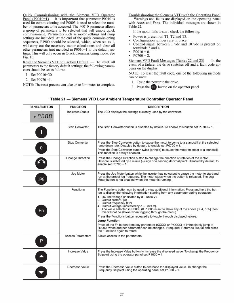
27
Quick Commissioning with the Siemens VFD OperatorPanel (P0010=1) — It is important that parameter P0010 isused for commissioning and P0003 is used to select the num-ber of parameters to be accessed. The P0010 parameter allowsa group of parameters to be selected that will enable quickcommissioning. Parameters such as motor settings and rampsettings are included. At the end of the quick commissioningsequences, P3900 should be selected, which, when set to 1,will carry out the necessary motor calculations and clear allother parameters (not included in P0010=1 to the default set-tings. This will only occur in Quick Commissioning mode. SeeFig. 16.Reset the Siemens VFD to Factory Default — To reset allparameters to the factory default settings; the following param-eters should be set as follows:
1. Set P0010=30.2. Set P0970 =1.
NOTE: The reset process can take up to 3 minutes to complete.
Troubleshooting the Siemens VFD with the Operating Panel— Warnings and faults are displayed on the operating panelwith Axxx and Fxxx. The individual messages are shown inTable 22.
If the motor fails to start, check the following:• Power is present on T1, T2 and T3.• Configuration jumpers are in place.• Control signal between 1 vdc and 10 vdc is present on
terminals 3 and 4.• P0010 = 0.• P0700 = 2.Siemens VFD Fault Messages (Tables 22 and 23) — In theevent of a failure, the drive switches off and a fault code ap-pears on the display.NOTE: To reset the fault code, one of the following methodscan be used:
1. Cycle the power to the drive.2. Press the button on the operator panel.
Table 21 — Siemens VFD Low Ambient Temperature Controller Operator Panel
Fn
PANEL/BUTTON FUNCTION DESCRIPTION
Indicates Status The LCD displays the settings currently used by the converter.
Start Converter The Start Converter button is disabled by default. To enable this button set P0700 = 1.
Stop Converter Press the Stop Converter button to cause the motor to come to a standstill at the selected ramp down rate. Disabled by default, to enable set P0700 = 1.Press the Stop Converter button twice (or hold) to cause the motor to coast to a standstill. This function is always enabled.
Change Direction Press the Change Direction button to change the direction of rotation of the motor. Reverse is indicated by a minus (–) sign or a flashing decimal point. Disabled by default, to enable set P0700 = 1.
Jog Motor Press the Jog Motor button while the inverter has no output to cause the motor to start and run at the preset jog frequency. The motor stops when the button is released. The Jog Motor button is not enabled when the motor is running.
Functions The Functions button can be used to view additional information. Press and hold the but-ton to display the following information starting from any parameter during operation:1. DC link voltage (indicated by d – units V).2. Output current. (A)3. Output frequency (Hz)4. Output voltage (indicated by o – units V).5. The value selected in P0005 (If P0005 is set to show any of the above [3, 4, or 5] then
this will not be shown when toggling through the menu).Press the Functions button repeatedly to toggle through displayed values.Jump FunctionPress of the Fn button from any parameter (rXXXX or PXXXX) to immediately jump to R0000, when another parameter can be changed, if required. Return to R0000 and press the Functions again to return.
Access Parameters Allows access to the parameters.
Increase Value Press the Increase Value button to increase the displayed value. To change the Frequency Setpoint using the operator panel set P1000 = 1.
Decrease Value Press the Decrease Value button to decrease the displayed value. To change theFrequency Setpoint using the operating panel set P1000 = 1.
0
jog
Fn
P

28
P0010 Start Quick Commissioning0 Ready to Run1 Quick Commissioning30 Factory SettingNOTE: P0010 must always be set back to ‘0’ before operating the motor. However if P3900 = 1 is set after commissioning this is done automatically.
P0100 Operation0 Power in kW; f default 50 Hz1 Power in hp; f default 60 Hz2 Power in kW; f default 60 HzNOTE: Settings 0 and 1 should be changed using the DIP switches to allow permanent setting.
P0304 Rated Motor Voltage*10 V — 2000 VNominal motor voltage (V) from rating plate
P0305 Rated Motor Current*0 — 2 x inverter rated current (A)Nominal motor current (A) from rating plate
P0307 Rated Motor Power*0 kW — 2000 kWNominal motor power (kW) from rating plate.If P0100 = 1, values will be in hp
P0310 Rated Motor Frequency*12 Hz — 650 HzNominal motor frequency (Hz) from rating plate
P0311 Rated Motor Speed*0 — 4000 1/minNominal motor speed (rpm) from rating plate
P0700 Selection of Command Source(on/off/reverse)0 Factory Setting1 Basic Operator Panel2 Terminal/Digital Inputs (default)
P1000 Selection of Frequency Setpoint0 No frequency setpoint1 Operator panel frequency control 2 Analog Setpoint (default)
P1080 Min. Motor FrequencySets minimum motor frequency (0-650Hz) at which the motor will run independent of the frequency setpoint. The value set here is valid for both clockwise and counterclockwise rotation.
P1082 Max. Motor FrequencySets maximum motor frequency (0-650Hz) at which the motor will run at independent of the frequency setpoint. The value set here is valid for both clockwise and counterclockwise rotation.
P1120 Ramp-Up Time0 s - 650 sTime taken for the motor to accelerate from standstill up to maximum motor frequency.
P1121 Ramp-Down Time0 s - 650 sTime taken for motor to decelerate from maximum motorfrequency down to a standstill.
P3900 End Quick Commissioning0 End Quick Commissioning without motor calculation or
factory reset.1 End Quick Commissioning with motor calculation and
factory reset (Recommended)2 End Quick Commissioning with motor calculation and with
I/O reset3 End Quick Commissioning with motor calculation but
without I/O reset
*Motor-specific parameters — see motor rating plate.NOTE: Shaded boxes are for reference only.
Fig. 16 — Siemens VFD Low Ambient Temperature Controller Flow Chart Quick Commissioning
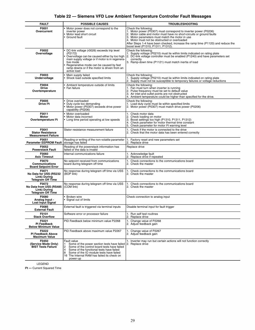
29
Table 22 — Siemens VFD Low Ambient Temperature Controller Fault Messages
LEGENDI2t — Current Squared Time
FAULT POSSIBLE CAUSES TROUBLESHOOTING
F0001Overcurrent
• Motor power does not correspond to the inverter power
• Motor lead short circuit• Ground fault
Check the following:1. Motor power (P0307) must correspond to inverter power (P0206)2. Motor cable and motor must have no short-circuits or ground faults3. Motor parameters must match the motor in use4. Motor must not be obstructed or overloadedAfter Steps 1-4 have been checked, increase the ramp time (P1120) and reduce the boost level (P1310, P1311, P1312).
F0002Overvoltage
• DC-link voltage (r0026) exceeds trip level (P2172)
• Overvoltage can be caused either by too high main supply voltage or if motor is in regenera-tive mode
• Regenerative mode can be caused by fast ramp downs or if the motor is driven from an active load
Check the following:1. Supply voltage (P0210) must lie within limits indicated on rating plate2. DC-link voltage controller must be enabled (P1240) and have parameters set
correctly3. Ramp-down time (P1121) must match inertia of load
F0003Undervoltage
• Main supply failed• Shock load outside specified limits
Check the following:1. Supply voltage (P0210) must lie within limits indicated on rating plate2. Supply must not be susceptible to temporary failures or voltage reductions
F0004Drive
Overtemperature
• Ambient temperature outside of limits• Fan failure
Check the following:1. Fan must turn when inverter is running2. Pulse frequency must be set to default value3. Air inlet and outlet points are not obstructed4. Ambient temperature could be higher than specified for the drive.
F0005Drive I2t
• Drive overloaded• Duty cycle too demanding• Motor power (P0307) exceeds drive power
capability (P0206)
Check the following:1. Load duty cycle must lie within specified limits2. Motor power (P0307) must match drive power (P0206)
F0011Motor
Overtemperature I2t
• Motor overloaded• Motor data incorrect• Long time period operating at low speeds
1. Check motor data2. Check loading on motor3. Boost settings too high (P1310, P1311, P1312)4. Check parameter for motor thermal time constant5. Check parameter for motor I2t warning level
F0041Stator Resistance
Measurement Failure
Stator resistance measurement failure 1. Check if the motor is connected to the drive2. Check that the motor data has been entered correctly
F0051Parameter EEPROM Fault
Reading or writing of the non-volatile parameter storage has failed
1. Factory reset and new parameters set2. Replace drive
F0052Powerstack Fault
Reading of the powerstack information has failed or the data is invalid
Replace drive
F0060Asic Timeout
Internal communications failure 1. Acknowledge fault2. Replace drive if repeated
F0070Communications
Board Setpoint Error
No setpoint received from communications board during telegram off time
1. Check connections to the communications board2. Check the master
F0071No Data for USS (RS232
Link) DuringTelegram Off Time
No response during telegram off time via USS(BOP link)
1. Check connections to the communications board2. Check the master
F0072No Data from USS (RS485
Link) DuringTelegram Off Time
No response during telegram off time via USS (COM link)
1. Check connections to the communications board2. Check the master
F0080Analog Input -
Lost Input Signal
• Broken wire• Signal out of limits
Check connection to analog input
F0085External Fault
External fault is triggered via terminal inputs Disable terminal input for fault trigger
F0101Stack Overflow
Software error or processor failure 1. Run self test routines2. Replace drive
F0221PI Feedback
Below Minimum Value
PID Feedback below minimum value P2268 1. Change value of P22682. Adjust feedback gain
F0222PI Feedback Above
Maximum Value
PID Feedback above maximum value P2267 1. Change value of P22672. Adjust feedback gain
F0450(Service Mode Only)BIST Tests Failure
Fault value1 Some of the power section tests have failed2 Some of the control board tests have failed4 Some of the functional tests have failed8 Some of the IO module tests have failed16 The Internal RAM has failed its check on
power-up
1. Inverter may run but certain actions will not function correctly2. Replace drive
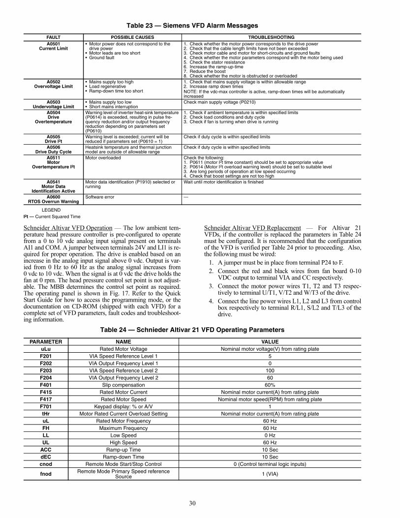
30
Table 23 — Siemens VFD Alarm Messages
LEGENDI2t — Current Squared Time
Schneider Altivar VFD Operation — The low ambient tem-perature head pressure controller is pre-configured to operatefrom a 0 to 10 vdc analog input signal present on terminalsAI1 and COM. A jumper between terminals 24V and LI1 is re-quired for proper operation. The drive is enabled based on anincrease in the analog input signal above 0 vdc. Output is var-ied from 0 Hz to 60 Hz as the analog signal increases from0 vdc to 10 vdc. When the signal is at 0 vdc the drive holds thefan at 0 rpm. The head pressure control set point is not adjust-able. The MBB determines the control set point as required.The operating panel is shown in Fig. 17. Refer to the QuickStart Guide for how to access the programming mode, or thedocumentation on CD-ROM (shipped with each VFD) for acomplete set of VFD parameters, fault codes and troubleshoot-ing information.
Schneider Altivar VFD Replacement — For Altivar 21VFDs, if the controller is replaced the parameters in Table 24must be configured. It is recommended that the configurationof the VFD is verified per Table 24 prior to proceeding. Also,the following must be wired:
1. A jumper must be in place from terminal P24 to F.2. Connect the red and black wires from fan board 0-10
VDC output to terminal VIA and CC respectively.3. Connect the motor power wires T1, T2 and T3 respec-
tively to terminal U/T1, V/T2 and W/T3 of the drive.4. Connect the line power wires L1, L2 and L3 from control
box respectively to terminal R/L1, S/L2 and T/L3 of thedrive.
Table 24 — Schnieder Altivar 21 VFD Operating Parameters
FAULT POSSIBLE CAUSES TROUBLESHOOTINGA0501
Current Limit• Motor power does not correspond to the
drive power• Motor leads are too short• Ground fault
1. Check whether the motor power corresponds to the drive power2. Check that the cable length limits have not been exceeded3. Check motor cable and motor for short-circuits and ground faults4. Check whether the motor parameters correspond with the motor being used5. Check the stator resistance6. Increase the ramp-up-time7. Reduce the boost8. Check whether the motor is obstructed or overloaded
A0502Overvoltage Limit
• Mains supply too high• Load regenerative• Ramp-down time too short
1. Check that mains supply voltage is within allowable range2. Increase ramp down timesNOTE: If the vdc-max controller is active, ramp-down times will be automatically increased
A0503Undervoltage Limit
• Mains supply too low• Short mains interruption
Check main supply voltage (P0210)
A0504Drive
Overtemperature
Warning level of inverter heat-sink temperature (P0614) is exceeded, resulting in pulse fre-quency reduction and/or output frequency reduction depending on parameters set (P0610)
1. Check if ambient temperature is within specified limits2. Check load conditions and duty cycle3. Check if fan is turning when drive is running
A0505Drive I2t
Warning level is exceeded; current will be reduced if parameters set (P0610 = 1)
Check if duty cycle is within specified limits
A0506Drive Duty Cycle
Heatsink temperature and thermal junction model are outside of allowable range
Check if duty cycle is within specified limits
A0511Motor
Overtemperature I2t
Motor overloaded Check the following:1. P0611 (motor I2t time constant) should be set to appropriate value2. P0614 (Motor I2t overload warning level) should be set to suitable level3. Are long periods of operation at low speed occurring4. Check that boost settings are not too high
A0541Motor Data
Identification Active
Motor data identification (P1910) selected or running
Wait until motor identification is finished
A0600RTOS Overrun Warning
Software error —
PARAMETER NAME VALUEuLu Rated Motor Voltage Nominal motor voltage(V) from rating plateF201 VIA Speed Reference Level 1 5F202 VIA Output Frequency Level 1 0F203 VIA Speed Reference Level 2 100F204 VIA Output Frequency Level 2 60F401 Slip compensation 60%F415 Rated Motor Current Nominal motor current(A) from rating plateF417 Rated Motor Speed Nominal motor speed(RPM) from rating plateF701 Keypad display: % or A/V 1tHr Motor Rated Current Overload Setting Nominal motor current(A) from rating plateuL Rated Motor Frequency 60 HzFH Maximum Frequency 60 HzLL Low Speed 0 HzUL High Speed 60 Hz
ACC Ramp-up Time 10 SecdEC Ramp-down Time 10 Seccnod Remote Mode Start/Stop Control 0 (Control terminal logic inputs)
fnod Remote Mode Primary Speed reference Source 1 (VIA)

31
Cooler Pump Control (ConfigurationOPTNPUMP) — The 30RB units can be configured for coolerpump control. Cooler Pumps Sequence is the variable thatmust be confirmed in the field. Proper configuration of thecooler pump control is required to provide reliable chiller oper-ation. The factory default setting for Cooler Pumps Sequence isPUMP=0 (No Pump), for units without the factory-installedhydronic package. For units with the hydronic package, thefactory default setting for Cooler Pumps Sequence is PUMP=1(1 pump only) for single pump units, or PUMP=2 (2 pumpsauto) for dual pump units. For dual pump hydronic optionunits, three control options exist. If the Cooler Pumps Se-quence (PUMP) is set to 2, the control will start the pumps andautomatically alternate the operation of the pumps to even thewear of the pumps. If a flow failure is detected, the other pumpwill attempt to start. Two manual control options also exist.When the Cooler Pumps Sequence is set to PUMP=3 CoolerPump 1 will always operate. When the Cooler Pumps Se-quence is set to PUMP=4 Cooler Pump 2 will always operate.
It is recommended for all chillers that the cooler pump con-trol be utilized unless the chilled water pump runs continuouslyor the chilled water system contains a suitable concentration ofantifreeze solution. When the Cooler Pumps Sequence is config-ured, the cooler pump output will be energized when the chillerenters an “ON” mode. The cooler pump output is also energizedwhen certain alarms are generated. The cooler pump output
should be used as an override to the external pump control ifcooler pump control is not utilized. The cooler pump output isenergized if a P.01 Water Exchanger Freeze Protection alarm isgenerated, which provides additional freeze protection if the sys-tem is not protected with a suitable antifreeze solution.
For all Cooler Pumps Sequence (PUMP) settings (including0), closure of both the chilled water flow switch (CWFS) andthe chilled water pump interlock contact (connected acrossTB-5 terminals 1 and 2) are required. In addition, for CoolerPumps Sequence settings of PUMP = 1, 2, 3, 4, normally openauxiliary contacts for Pump 1 and Pump 2 (wired in parallel)must be connected to the violet and pink wires located in theharness from the MBB-J5C-CH18 connector. The wires in theharness are marked “PMP1-13” and “PMP1-14.” See the fieldwiring diagram in the 30RB Installation Instructions.
Regardless of the cooler pump control option selected, ifthe chilled water flow switch/interlock does not close withinthe MINUTES OFF TIME (ConfigurationOPTNDELY) period after the unit is enabled and in an ON mode,alarm P.14 will be generated. Other conditions which will trig-ger this alarm include:• Cooler pump interlock is open for at least 30 seconds
during chiller operation.• Lag chiller in Master/Slave Control pump interlock does
not close after 1 minute of the pump start command.
RUN
PRG
MON
%
Hz
MODELocRem
ENT
RUN STOP
13
1
2
3
6
7
4
5
9
10
11
14
12
8
Fig. 17 — Schnieder Altivar 21 VFD Display Panel
CALLOUT LED/KEY DESCRIPTION
1Display RUN LED
Illuminates when a run command is applied to the drive controller. Flashes when a speed reference is present with the run command.
2 Display PRG LED
Illuminates when Programming mode is active. Flashes when -GrU menus are active.
3 Display MON LED
Illuminates when Monitoring mode is active. Flashes in fault record display mode.
4 Display Unit
4 digits, 7 segments
5Display Unit LED
The % LED illuminates when a displayed numeric value is a percentage. The Hz LED illuminates when a displayed numeric value is in hertz.
6Up/Down arrows
Depending on the mode, use the arrows to: navigate between the menus, change a value, or change the speed reference when Up/Down LED (7) is lit.
7 Up/Down LED
Illuminates when the Up/Down arrows are controlling the speed reference.
8 Loc/Rem LED
Illuminates when Local mode is selected.
CALLOUT LED/KEY DESCRIPTION
9
MODE Press to select the Keypad mode. Modes are: Run mode (default on power-up), Programming mode, and Monitoring mode. Can also be used to go back to the previous menu.
10 Loc/Rem Switches between Local and Remote modes.
11 ENT Press to display a parameter’s value or to save a changed value.
12 RUN LED Illuminates when the Run key is enabled.
13 RUN Pressing this key when the RUN LED is illuminated starts the drive controller.
14
STOP Stop/reset key. In Local mode, pressing the STOP key causes the drive controller to stop based on the setting of parameter F721. In Remote mode, pressing the STOP key causes the drive controller to stop based on the setting of parameter F603. The display will indicate a flashing “E”. If F735 is set to 0 (default setting), press-ing the stop key twice will reset all resettable faults if the fault condition has been resolved.

32
• Cooler pump control is enabled and the chilled waterflow switch/interlock is closed for more than 2 minutesfollowing a command to shut down the pump.The last alarm criterion can be disabled. If Flow Checked if
Pmp Off (ConfigurationOPTNP.LOC) is set to NO, thecontrol will ignore the pump interlock input if the cooler pumpoutput is OFF.
The ComfortLink™ controls is the ability to periodicallystart the pumps to maintain the bearing lubrication and seal in-tegrity. If Periodic Pump Start (ConfigurationOPTNPM.PS) is set to YES, and if the unit is off at 2:00PM, a pump will be started once each day for 2 seconds. If theunit has 2 pumps, Pump 1 will be started on even days (such asday 2, 4, or 6 of the month); Pump 2 will be started on odddays. The default for this option is PM.PS=NO.
The pump will continue to run for 60 seconds after an offcommand is issued.
Machine Control Methods — Three variables controlhow the machine operates. One variable controls the machineOn-Off function. The second controls the set point operation.The third variable controls the Heat-Cool operation which isalways set to cool. Table 25 illustrates how the control methodand cooling set point select variables direct the operation of thechiller and the set point to which it controls. Table 25 alsoprovides the On/Off state of the machine for the givencombinations.
Machine On/Off control is determined by the configurationof the Operating Type Control (Operating ModesSLCTOPER). Options to control the machine locally via a switch,on a local Time Schedule, or via a Carrier Comfort Network®
command are offered.SWITCH CONTROL — In this Operating Type Control, theEnable/Off/Remote Contact switch controls the machine locally.All models are factory configured with OPER=0 (Switch Con-trol). With the OPER set to 0, simply switching the Enable/Off/Remote Contact switch to the Enable or Remote Contact posi-tion (external contacts closed) will put the chiller in an occupiedstate. The unit Occupied Status (Run StatusVIEWOCC)will change from NO to YES. The Status Unit Control Type
(Run StatusVIEWCTRL) will change from 0 (Local Off)when the switch is Off to 1 (Local On) when in the Enable posi-tion or Remote Contact position with external contacts closed.TIME SCHEDULE — In this Operating Type Control, themachine operates under a local schedule programmed by theuser as long as the Enable/Off/Remote Contact switch is in theEnable or Remote Contact position (external contacts closed).To operate under this Operating Type Control, OperatingModesSLCT must be set to OPER=1. Two Internal TimeSchedules are available. Time Schedule 1 (Time ClockSCH1) is used for single set point On-Off control. Time Sched-ule 2 (Time ClockSCH2) is used for dual set point On-Offand Occupied-Unoccupied set point control. The control willuse the operating schedules as defined under the Time Clockmode in the scrolling marquee display.CCN Global Time Schedule — A CCN Global Schedule canbe utilized. The schedule number can be set anywhere from 65to 99 for operation under a CCN global schedule. The 30RBchillers can be configured to follow a CCN Global TimeSchedule broadcast by another system element. The Comfort-VIEW™ Network Manager’s Configure and Modify com-mands or the Service Tool’s Modify/Names function must beused to change the number of the Occupancy Equipment PartTable Name (OCC1P01E) to the Global Schedule Number.The Schedule Number can be set from 65 to 99 (OCC1P65E).
The Occupancy Supervisory Part table name (OCC1P01S)number must be changed to configure the unit to broadcast aGlobal Time Schedule. The Schedule Number can be set from65 to 99 (OCC1P65S). When OCC1PxxS is set to a value great-er than 64, an occupancy flag is broadcast over the CCN everytime it transitions from occupied to unoccupied or vice-versa.By configuring their appropriate Time Schedule decisions to thesame number, other devices on the network can follow thissame schedule. The Enable/Off/Remote Contact must be in theEnable position or Remote Contact position with the contactsclosed for the unit to operate. The Status Unit Control Type(Run StatusVIEWSTAT) will be 0 (Local Off) when theswitch is Off. The Status Unit Control Type will be 2 (CCN)when the Enable/Off/Remote Contact switch input is On.
Table 25 — Control Methods and Cooling Set Points
— = No Effect
PARAMETERACTIVE
SETPOINT
Control Method (OPER)
Heat Cool Select
(HC.SE)
Setpoint Select (SP.SE)
Ice Mode Enable(ICE.M)
Ice Done(ICE.D)
Dual Setpoint Switch (DUAL)
Setpoint Occupied (SP.OC)
0 (Switch Ctrl)
0(Cool)
1(Setpoint1)
— — — — CSP.1Enable Open Closed — CSP.3
2(Setpoint2)
— — — — CSP.2Enable Open Closed — CSP.3
3(4-20mA Setp) — — — — 4-20 mA
— EnableOpen
Open — CSP.1Closed — CSP.3
Closed Closed — CSP.2
4(Dual Setp Sw)
— —Open — CSP.1
Closed — CSP.2
EnabledOpen Closed — CSP.3
Closed Closed — CSP.2
1 (Time Sched)
0(Cool)
0(Setpoint Occ)
— — —Occupied CSP.1
Unoccupied CSP.2
EnableOpen —
UnoccupiedCSP.3
Closed — CSP.2
2(CCN)
0(Cool) —
— —— Occupied CSP.1— Unoccupied CSP.2
Enable Open — Unoccupied CSP.3
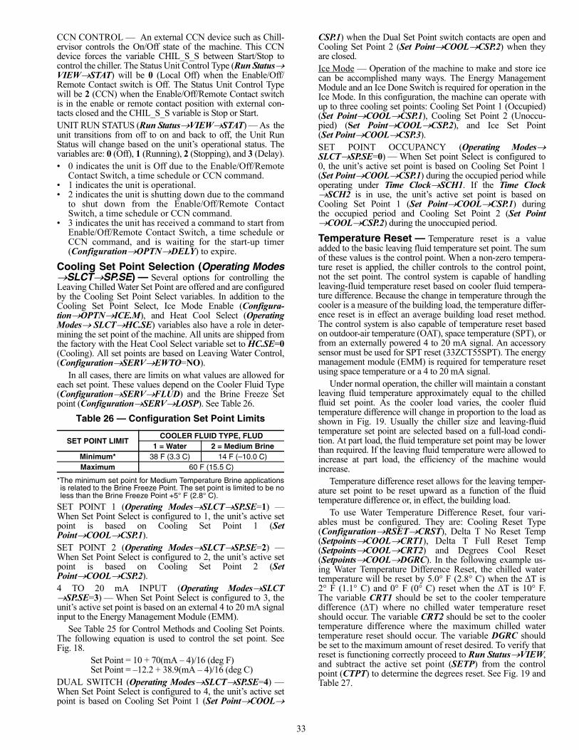
33
CCN CONTROL — An external CCN device such as Chill-ervisor controls the On/Off state of the machine. This CCNdevice forces the variable CHIL_S_S between Start/Stop tocontrol the chiller. The Status Unit Control Type (Run StatusVIEWSTAT) will be 0 (Local Off) when the Enable/Off/Remote Contact switch is Off. The Status Unit Control Typewill be 2 (CCN) when the Enable/Off/Remote Contact switchis in the enable or remote contact position with external con-tacts closed and the CHIL_S_S variable is Stop or Start.UNIT RUN STATUS (Run StatusVIEWSTAT) — As theunit transitions from off to on and back to off, the Unit RunStatus will change based on the unit’s operational status. Thevariables are: 0 (Off), 1 (Running), 2 (Stopping), and 3 (Delay).• 0 indicates the unit is Off due to the Enable/Off/Remote
Contact Switch, a time schedule or CCN command.• 1 indicates the unit is operational.• 2 indicates the unit is shutting down due to the command
to shut down from the Enable/Off/Remote ContactSwitch, a time schedule or CCN command.
• 3 indicates the unit has received a command to start fromEnable/Off/Remote Contact Switch, a time schedule orCCN command, and is waiting for the start-up timer(ConfigurationOPTNDELY) to expire.
Cooling Set Point Selection (Operating ModesSLCTSP.SE) — Several options for controlling theLeaving Chilled Water Set Point are offered and are configuredby the Cooling Set Point Select variables. In addition to theCooling Set Point Select, Ice Mode Enable (Configura-tionOPTNICE.M), and Heat Cool Select (OperatingModesSLCTHC.SE) variables also have a role in deter-mining the set point of the machine. All units are shipped fromthe factory with the Heat Cool Select variable set to HC.SE=0(Cooling). All set points are based on Leaving Water Control,(ConfigurationSERVEWTO=NO).
In all cases, there are limits on what values are allowed foreach set point. These values depend on the Cooler Fluid Type(ConfigurationSERVFLUD) and the Brine Freeze Setpoint (ConfigurationSERVLOSP). See Table 26.
Table 26 — Configuration Set Point Limits
*The minimum set point for Medium Temperature Brine applicationsis related to the Brine Freeze Point. The set point is limited to be noless than the Brine Freeze Point +5° F (2.8° C).
SET POINT 1 (Operating ModesSLCTSP.SE=1) —When Set Point Select is configured to 1, the unit’s active setpoint is based on Cooling Set Point 1 (SetPointCOOLCSP.1).SET POINT 2 (Operating ModesSLCTSP.SE=2) —When Set Point Select is configured to 2, the unit’s active setpoint is based on Cooling Set Point 2 (SetPointCOOLCSP.2).4 TO 20 mA INPUT (Operating ModesSLCTSP.SE=3) — When Set Point Select is configured to 3, theunit’s active set point is based on an external 4 to 20 mA signalinput to the Energy Management Module (EMM).
See Table 25 for Control Methods and Cooling Set Points.The following equation is used to control the set point. SeeFig. 18.
Set Point = 10 + 70(mA – 4)/16 (deg F)Set Point = –12.2 + 38.9(mA – 4)/16 (deg C)
DUAL SWITCH (Operating ModesSLCTSP.SE=4) —When Set Point Select is configured to 4, the unit’s active setpoint is based on Cooling Set Point 1 (Set PointCOOL
CSP.1) when the Dual Set Point switch contacts are open andCooling Set Point 2 (Set PointCOOLCSP.2) when theyare closed.Ice Mode — Operation of the machine to make and store icecan be accomplished many ways. The Energy ManagementModule and an Ice Done Switch is required for operation in theIce Mode. In this configuration, the machine can operate withup to three cooling set points: Cooling Set Point 1 (Occupied)(Set PointCOOLCSP.1), Cooling Set Point 2 (Unoccu-pied) (Set PointCOOLCSP.2), and Ice Set Point(Set PointCOOLCSP.3).SET POINT OCCUPANCY (Operating ModesSLCTSP.SE=0) — When Set point Select is configured to0, the unit’s active set point is based on Cooling Set Point 1(Set PointCOOLCSP.1) during the occupied period whileoperating under Time ClockSCH1. If the Time ClockSCH2 is in use, the unit’s active set point is based onCooling Set Point 1 (Set PointCOOLCSP.1) duringthe occupied period and Cooling Set Point 2 (Set PointCOOLCSP.2) during the unoccupied period.
Temperature Reset — Temperature reset is a valueadded to the basic leaving fluid temperature set point. The sumof these values is the control point. When a non-zero tempera-ture reset is applied, the chiller controls to the control point,not the set point. The control system is capable of handlingleaving-fluid temperature reset based on cooler fluid tempera-ture difference. Because the change in temperature through thecooler is a measure of the building load, the temperature differ-ence reset is in effect an average building load reset method.The control system is also capable of temperature reset basedon outdoor-air temperature (OAT), space temperature (SPT), orfrom an externally powered 4 to 20 mA signal. An accessorysensor must be used for SPT reset (33ZCT55SPT). The energymanagement module (EMM) is required for temperature resetusing space temperature or a 4 to 20 mA signal.
Under normal operation, the chiller will maintain a constantleaving fluid temperature approximately equal to the chilledfluid set point. As the cooler load varies, the cooler fluidtemperature difference will change in proportion to the load asshown in Fig. 19. Usually the chiller size and leaving-fluidtemperature set point are selected based on a full-load condi-tion. At part load, the fluid temperature set point may be lowerthan required. If the leaving fluid temperature were allowed toincrease at part load, the efficiency of the machine wouldincrease.
Temperature difference reset allows for the leaving temper-ature set point to be reset upward as a function of the fluidtemperature difference or, in effect, the building load.
To use Water Temperature Difference Reset, four vari-ables must be configured. They are: Cooling Reset Type(ConfigurationRSETCRST), Delta T No Reset Temp(SetpointsCOOLCRT1), Delta T Full Reset Temp(SetpointsCOOLCRT2) and Degrees Cool Reset(SetpointsCOOLDGRC). In the following example us-ing Water Temperature Difference Reset, the chilled watertemperature will be reset by 5.0° F (2.8° C) when the T is2° F (1.1° C) and 0° F (0° C) reset when the T is 10° F.The variable CRT1 should be set to the cooler temperaturedifference (T) where no chilled water temperature resetshould occur. The variable CRT2 should be set to the coolertemperature difference where the maximum chilled watertemperature reset should occur. The variable DGRC shouldbe set to the maximum amount of reset desired. To verify thatreset is functioning correctly proceed to RunStatusVIEW,and subtract the active set point (SETP) from the controlpoint (CTPT) to determine the degrees reset. See Fig. 19 andTable 27.
SET POINT LIMITCOOLER FLUID TYPE, FLUD
1 = Water 2 = Medium BrineMinimum* 38 F (3.3 C) 14 F (–10.0 C)Maximum 60 F (15.5 C)
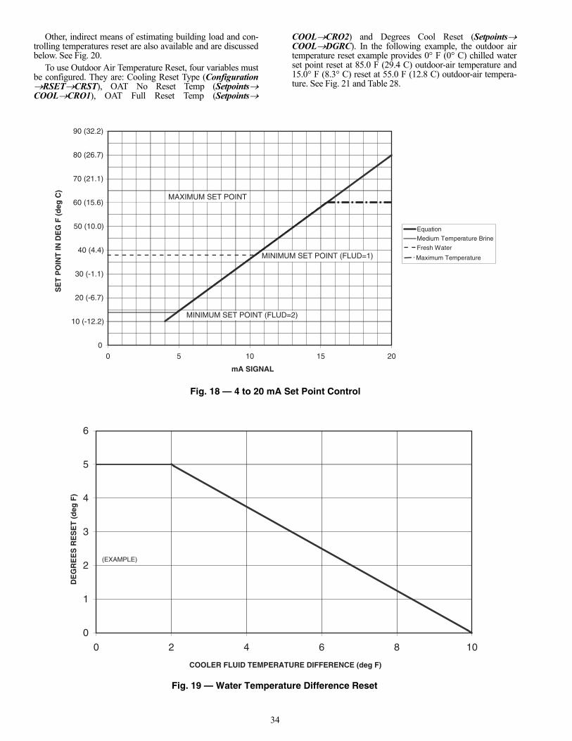
34
Other, indirect means of estimating building load and con-trolling temperatures reset are also available and are discussedbelow. See Fig. 20.
To use Outdoor Air Temperature Reset, four variables mustbe configured. They are: Cooling Reset Type (ConfigurationRSETCRST), OAT No Reset Temp (SetpointsCOOLCRO1), OAT Full Reset Temp (Setpoints
COOLCRO2) and Degrees Cool Reset (SetpointsCOOLDGRC). In the following example, the outdoor airtemperature reset example provides 0° F (0° C) chilled waterset point reset at 85.0 F (29.4 C) outdoor-air temperature and15.0° F (8.3° C) reset at 55.0 F (12.8 C) outdoor-air tempera-ture. See Fig. 21 and Table 28.
Maximum Temperature
0
0 (-12.2)1
0 (-6.7)2
0 (-1.1)3
0 (4.4)4
50 (10.0)
0 (15.6)6
0 (21.1)7
0 (26.7)8
0 (32.2)9
02510150
mA SIGNAL
SE
T P
OIN
T IN
DE
G F
(d
eg C
)
noitauqE
enirBeruatrepmeTmuideM
retaWhserF
MAXIMUM SET POINT
MINIMUM SET POINT (FLUD=1)
MINIMUM SET POINT (FLUD=2)
Fig. 18 — 4 to 20 mA Set Point Control
0
1
2
3
4
5
6
0186420
COOLER FLUID TEMPERATURE DIFFERENCE (deg F)
DE
GR
EE
SR
ES
ET
(d
egF
)
(EXAMPLE)
Fig. 19 — Water Temperature Difference Reset
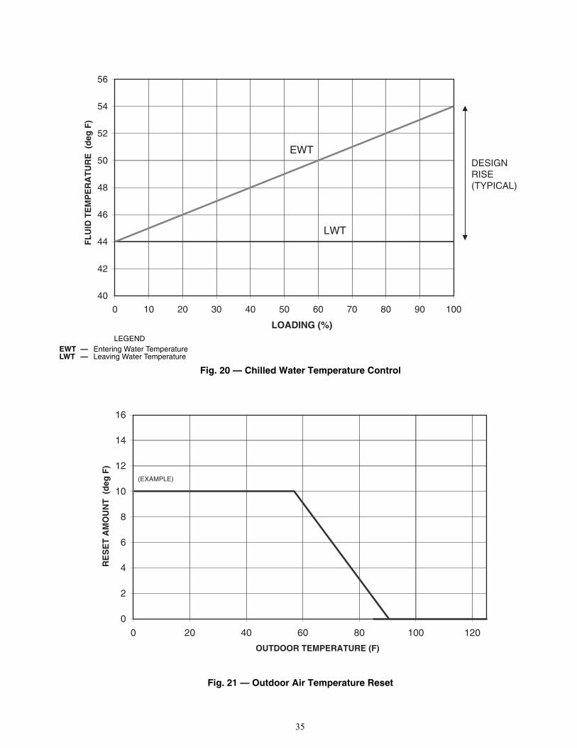
35
04
24
44
64
84
05
25
45
65
0010908070605040302010
LOADING (%)
FL
UID
TE
MP
ER
AT
UR
E (
deg
F)
TWE
TWL
DESIGNRISE(TYPICAL)
0
2
4
6
8
01
21
41
61
021001080604020
OUTDOOR TEMPERATURE (F)
RE
SE
T A
MO
UN
T (
deg
F)
(EXAMPLE)
LEGEND
Fig. 20 — Chilled Water Temperature Control
EWT — Entering Water TemperatureLWT — Leaving Water Temperature
Fig. 21 — Outdoor Air Temperature Reset

36
Table 27 — Water Temperature Difference Reset Configuration
NOTE: Bold values indicate sub-mode level.
MODE KEYPAD ENTRY DISPLAY ITEM EXPANSION COMMENTCONFIGURATION DISP
UNIT
SERV
OPTN
RSET Reset Cool and Heat Tmp
CRST Cooling Reset Type
0 No Reset
0 No Reset Flashing to indicate Edit mode. May require Password
/ 2 Delta T Temp Use up or down arrows to change value to 2.
2 Accepts the change.
CRST
At mode level
SETPOINTS / Change to Setpoints Mode
COOL Cooling Setpoints
CSP.1 Cooling Setpoint 1
x 4 CRV.2
CRT1 Delta T No Reset Temp Cooler Temperature difference where no temperature reset is required.
0 Value of CRT1
0 Flashing to indicate Edit mode
10.0 Value of No Temperature Reset, 10 from the example.
10.0 Accepts the change.
CRT1
CRT2 Delta T Full Reset Temp Cooler Temperature difference where full temperature reset, DGRC is required.
0 Value of CRT2.
0 Flashing to indicate Edit mode
2.0 Value of full Temperature Reset, 2 from the example.
2.0 Accepts the change.
CRT2
x 4 CRS2
DGRC Degrees Cool Reset Amount of temperature reset required.
0 Value of DGRC
0 Flashing to indicate Edit mode
5.0 Amount of Temperature Reset required, 5 from the example.
5.0 Accepts the change.
DGRC
ENTER
ENTER
ENTER
ENTER
ENTER
ESCAPE
ESCAPE
ENTER
ENTER
ENTER
ENTER
ENTER
ESCAPE
ENTER
ENTER
ENTER
ESCAPE
ENTER
ENTER
ENTER
ESCAPE

37
Table 28 — OAT Reset Configuration
NOTE: Bold values indicate sub-mode level.
MODE KEYPAD ENTRY DISPLAY ITEM EXPANSION COMMENTCONFIGURATION DISP
UNIT
SERV
OPTN
RSET Reset Cool and Heat Tmp
CRST Cooling Reset Type
0 No Reset
0 No Reset Flashing to indicate Edit mode. May require Password
/ 1 Out Air Temp Use up or down arrows to change value to 1.
1 Accepts the change.
CRST
At mode level
SETPOINTS / Change to Setpoints Mode
COOL Cooling Setpoints
CSP.1 Cooling Setpoint 1
x 6 CRT.2
CRO1 OAT No Reset Temp Outdoor Temperature where no temperature reset is required.
0 Value of CRO1
0 Flashing to indicate Edit mode
85.0 Value of No Temperature Reset, 85 from the example.
85.0 Accepts the change.
CRO1
CRO2 OAT Full Reset Temp Outdoor Temperature where full temperature reset, DGRC is required.
0 Value of CRO2.
0 Flashing to indicate Edit mode
55.0 Value of full Temperature Reset, 55 from the example.
55.0 Accepts the change.
CRO2
CRS1
CRS2
DGRC Degrees Cool Reset Amount of temperature reset required.
0 Value of DGRC
0 Flashing to indicate Edit mode
15.0 Amount of Temperature Reset required, 15 from the example.
15.0 Accepts the change.
DGRC
ENTER
ENTER
ENTER
ENTER
ENTER
ESCAPE
ESCAPE
ENTER
ENTER
ENTER
ENTER
ENTER
ESCAPE
ENTER
ENTER
ENTER
ESCAPE
ENTER
ENTER
ENTER
ESCAPE

38
To use Space Temperature Reset in addition to the energymanagement module, four variables must be configured. Theyare: Cooling Reset Type (ConfigurationRSETCRST),Space T No Reset Temp (SetpointsCOOLCRS1), SpaceT Full Reset Temp (SetpointsCOOLCRS2) and DegreesCool Reset (SetpointsCOOLDGRC). In the followingspace temperature reset example, 0° F (0° C) chilled water setpoint reset at 72.0 F (22.2 C) space temperature and 6.0° F(3.3° C) reset at 68.0 F (20.0 C) space temperature. See Fig. 22and Table 29.
To use 4-20 mA Temperature Reset in addition to the ener-gy management module, four variables must be configured.They are: Cooling Reset Type (ConfigurationRSETCRST), Current No Reset Val (SetpointsCOOLCRV1),Current Full Reset Val (SetpointsCOOLCRV2) andDegrees Cool Reset (SetpointsCOOLDGRC). In the
following example, at 4 mA no reset takes place. At 20 mA,5° F (2.8° C) chilled water set point reset is required. SeeFig. 23 and Table 30.
CAUTION
Care should be taken when interfacing with other controlsystems due to possible power supply differences such as afull wave bridge versus a half wave rectification. Connec-tion of control devices with different power supplies mayresult in permanent damage. ComfortLink™ controlsincorporate power supplies with half wave rectification. Asignal isolation device should be utilized if the signalgenerator incorporates a full wave bridge rectifier.
SPACE TEMPERATURE (F)
DE
GR
EE
S R
ES
ET
(d
egF
)
60 62 64 66 68 70 72 74 76 78 80
0
1
2
3
4
5
6
7(EXAMPLE)
mA SIGNAL
DE
GR
EE
S R
ES
ET
(d
egF
)
20 4 6 8 10 12 14 16 18 20
0
1
2
3
4
5
6
Fig. 22 — Space Temperature Reset
Fig. 23 — 4 to 20 mA Temperature Reset

39
Table 29 — Space Temperature Reset Configuration
NOTE: Bold values indicate sub-mode level.
MODE KEYPAD ENTRY DISPLAY ITEM EXPANSION COMMENTCONFIGURATION DISP
UNIT
SERV
OPTN
RSET Reset Cool and Heat Tmp
CRST Cooling Reset Type
0 No Reset
0 No Reset Flashing to indicate Edit mode. May require Password
/ 4 Space Temp Use up or down arrows to change value to 4.
4 Accepts the change.
CRST
At mode level
SETPOINTS / Change to Setpoints Mode
COOL Cooling Setpoints
CSP.1 Cooling Setpoint 1
x 8 CRO2
CRS1 Space T No Reset Temp Space Temperature where no temperature reset is required.
0 Value of CRS1
0 Flashing to indicate Edit mode
72.0 Value of No Temperature Reset, 72 from the example.
72.0 Accepts the change.
CRS1
CRS2 Space T Full Reset Temp Space Temperature where full temperature reset, DGRC is required.
0 Value of CRS2.
0 Flashing to indicate Edit mode
68.0 Value of full Temperature Reset, 68 from the example.
68.0 Accepts the change.
CRS2
DGRC Degrees Cool Reset Amount of temperature reset required.
0 Value of DGRC
0 Flashing to indicate Edit mode
6.0 Amount of Temperature Reset required, 6 from the example.
6.0 Accepts the change.
DGRC
ENTER
ENTER
ENTER
ENTER
ENTER
ESCAPE
ESCAPE
ENTER
ENTER
ENTER
ENTER
ENTER
ESCAPE
ENTER
ENTER
ENTER
ESCAPE
ENTER
ENTER
ENTER
ESCAPE
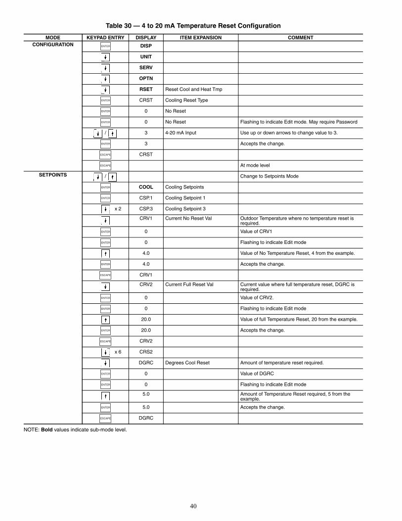
40
Table 30 — 4 to 20 mA Temperature Reset Configuration
NOTE: Bold values indicate sub-mode level.
MODE KEYPAD ENTRY DISPLAY ITEM EXPANSION COMMENTCONFIGURATION DISP
UNIT
SERV
OPTN
RSET Reset Cool and Heat Tmp
CRST Cooling Reset Type
0 No Reset
0 No Reset Flashing to indicate Edit mode. May require Password
/ 3 4-20 mA Input Use up or down arrows to change value to 3.
3 Accepts the change.
CRST
At mode level
SETPOINTS / Change to Setpoints Mode
COOL Cooling Setpoints
CSP.1 Cooling Setpoint 1
x 2 CSP.3 Cooling Setpoint 3
CRV1 Current No Reset Val Outdoor Temperature where no temperature reset is required.
0 Value of CRV1
0 Flashing to indicate Edit mode
4.0 Value of No Temperature Reset, 4 from the example.
4.0 Accepts the change.
CRV1
CRV2 Current Full Reset Val Current value where full temperature reset, DGRC is required.
0 Value of CRV2.
0 Flashing to indicate Edit mode
20.0 Value of full Temperature Reset, 20 from the example.
20.0 Accepts the change.
CRV2
x 6 CRS2
DGRC Degrees Cool Reset Amount of temperature reset required.
0 Value of DGRC
0 Flashing to indicate Edit mode
5.0 Amount of Temperature Reset required, 5 from the example.
5.0 Accepts the change.
DGRC
ENTER
ENTER
ENTER
ENTER
ENTER
ESCAPE
ESCAPE
ENTER
ENTER
ENTER
ENTER
ENTER
ESCAPE
ENTER
ENTER
ENTER
ESCAPE
ENTER
ENTER
ENTER
ESCAPE

41
Demand Limit — Demand limit is a feature that allowsthe unit capacity to be limited during periods of peak energyusage. There are three types of demand limiting that canbe configured. The first type is through 2-step switchcontrol, which will reduce the maximum capacity to 2 user-configurable percentages. The second type is by 4 to 20 mAsignal input which will reduce the maximum capacity linearlybetween 100% at a 4 mA input signal (no reduction) down tothe user-configurable level at a 20 mA input signal. The thirdtype uses the CCN Loadshed module and has the ability tolimit the current operating capacity to maximum and furtherreduce the capacity if required.NOTE: One-step Demand Limit is standard.
The 2-step switch control and 4 to 20-mA input signal typesof demand limiting require the energy management module(EMM).
To use demand limit, select the type of demand limiting touse. Then configure the demand limit set points based on thetype selected.2-STEP SWITCH CONTROLLED — If using 2-step de-mand limit control, an energy management module must be in-stalled. One-step demand limit control does not require the en-ergy management module. To configure demand limit for2-step switch control, three parameters must be configured:Demand Limit Select (ConfigurationRSETDMDC),Switch Limit Setpoint 1 (SetpointsMISCDLS1) andSwitch Limit Setpoint 2 (SetpointsMISCDLS2). In thefollowing example, Demand Limit Switch 1 is 60% and de-mand limit Switch 2 is 40%. Demand limit steps are controlledby two relay switch inputs field wired to TB5 for Switch 1 andTB6 for Switch 2. See Table 31.
For demand limit by 2-stage switch control, closing the firststage demand limit contact will put the unit on the first demandlimit level. The unit will not exceed the percentage of capacityentered as Demand Limit Switch 1 set point. Closing contactson the second demand limit switch prevents the unit from ex-ceeding the capacity entered as Demand Limit Switch 2 setpoint. The demand limit stage that is set to the lowest demandtakes priority if both demand limit inputs are closed. If the de-mand limit percentage does not match unit staging, the unitwill limit capacity to the closest capacity stage without exceed-ing the value. To disable demand limit configure DMDC to 0.
EXTERNALLY POWERED (4 to 20 mA Controlled) — Theenergy management module is required for 4 to 20 mAdemand limit control. To configure demand limit for 4 to20 mA control three parameters must be configured. They are:Demand Limit Select (ConfigurationRSETDMDC), mAfor 100% Demand Limit (ConfigurationRSETDMMX)and mA for 0% Demand Limit (ConfigurationRSETDMZE). In the following example, a 4 mA signal is DemandLimit 100% and a 20 mA Demand Limit signal is 0%. The 4 to20 mA signal is connected to TB6-1 and TB6-2. The demandlimit is a linear interpolation between the two values entered.See Table 32 and Fig. 24.
In Fig. 24, if the machine receives a 12 mA signal, themachine controls will limit the capacity to 50%.CCN LOADSHED CONTROLLED — To configure demandlimit for CCN Loadshed control, the unit Operating TypeControl must be in CCN control, (Operating ModesSLCTSP.SE=2) and be controlled by a Chillervisor module.The Chillervisor module can force the demand limit variableand directly control the capacity of the machine. Additionally,the unit’s set point will be artificially lowered to force the chill-er to load to the demand limit value.
Remote Alarm and Alert Relays — The 30RB chill-er can be equipped with a remote alert and remote alarmannunciator contacts. Both relays connected to these contactsmust be rated for a maximum power draw of 10 va sealed,25 va inrush at 24 volts. The alarm relay, indicating that thecomplete unit has been shut down can be connected to TB5-12and TB5-13. For an alert relay, indicating that at least 1 circuitwas off due to the alert, a field-supplied and installed relaymust be connected between MBB-J3-CH25-3 and TB5-13.
CAUTION
Care should be taken when interfacing with other controlsystems due to possible power supply differences such as afull wave bridge versus a half wave rectification. Connec-tion of control devices with different power supplies mayresult in permanent damage. ComfortLink™ controlsincorporate power supplies with half wave rectification. Asignal isolation device should be utilized if the signalgenerator incorporates a full wave bridge rectifier.
0
01
02
03
04
05
06
07
08
09
001
02816141210186420
DEMAND LIMIT SIGNAL (mA)
DE
MA
ND
LIM
IT (
%)
Fig. 24 — Demand Limit
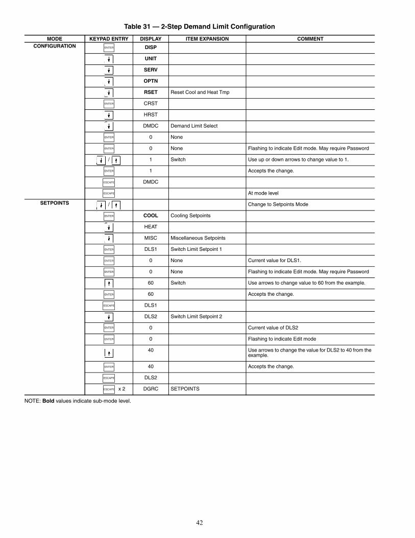
42
Table 31 — 2-Step Demand Limit Configuration
NOTE: Bold values indicate sub-mode level.
MODE KEYPAD ENTRY DISPLAY ITEM EXPANSION COMMENTCONFIGURATION DISP
UNIT
SERV
OPTN
RSET Reset Cool and Heat Tmp
CRST
HRST
DMDC Demand Limit Select
0 None
0 None Flashing to indicate Edit mode. May require Password
/ 1 Switch Use up or down arrows to change value to 1.
1 Accepts the change.
DMDC
At mode level
SETPOINTS / Change to Setpoints Mode
COOL Cooling Setpoints
HEAT
MISC Miscellaneous Setpoints
DLS1 Switch Limit Setpoint 1
0 None Current value for DLS1.
0 None Flashing to indicate Edit mode. May require Password
60 Switch Use arrows to change value to 60 from the example.
60 Accepts the change.
DLS1
DLS2 Switch Limit Setpoint 2
0 Current value of DLS2
0 Flashing to indicate Edit mode
40 Use arrows to change the value for DLS2 to 40 from the example.
40 Accepts the change.
DLS2
x 2 DGRC SETPOINTS
ENTER
ENTER
ENTER
ENTER
ENTER
ESCAPE
ESCAPE
ENTER
ENTER
ENTER
ENTER
ENTER
ESCAPE
ENTER
ENTER
ENTER
ESCAPE
ESCAPE

43
Table 32 — Externally Powered Demand Limit Configuration
NOTE: Bold values indicate sub-mode level.
PRE-START-UP
Do not attempt to start the chiller until the following checkshave been completed.
System Check1. Check auxiliary components, such as the chilled fluid
circulating pump, air-handling equipment, or otherequipment to which the chiller supplies liquid are opera-tional. Consult manufacturer’s instructions. If the unit hasfield-installed accessories, be sure all are properlyinstalled and wired correctly. Refer to unit wiringdiagrams.
2. Open compressor suction (if equipped) and dischargeshutoff valves.
3. Open liquid line shut off valves.4. Fill the chiller fluid circuit with clean water (with recom-
mended inhibitor added) or other non-corrosive fluid to
be cooled. Bleed all air out of high points of system. Anair vent is included with the cooler. If outdoor tempera-tures are expected to be below 32 F (0° C), sufficientinhibited propylene glycol or other suitable corrosioninhibited antifreeze should be added to the chiller watercircuit to prevent possible freeze-up.The chilled water loop must be cleaned before the unit isconnected. Units supplied with the accessory hydronicpackage include a run in screen. If the run-in screen is leftin the suction guide/strainer, it is recommended that theService Maintenance be set to alert the operator within24 hours of start-up to be sure that the run-in screen in thesuction guide/strainer is removed. To set the time for theparameter, go to Time ClockMCFGW.FIL. Valuesfor this item are counted as days. Refer to the hydronicpump package literature if unit is equipped with theoptional hydronic pump package.
5. Check tightness of all electrical connections.6. Oil should be visible in the compressor sight glass. An
acceptable oil level in the compressor is from 3/4 to 7/8full sight glass. Adjust the oil level as required. No oilshould be removed unless the crankcase heater has beenenergized for at least 24 hours. See Oil Charge section forCarrier-approved oils.
7. Electrical power source must agree with unit nameplate.
MODE KEYPAD ENTRY DISPLAY ITEM EXPANSION COMMENTCONFIGURATION DISP
UNIT
SERV
OPTN
RSET Reset Cool and Heat Tmp
CRST
HRST
DMDC Demand Limit Select
0 None
0 None Flashing to indicate Edit mode. May require Password
2 4-20 mA Input Use up arrows to change value to 2.
2 Accepts the change.
DMDC
DMMX mA for 100% Demand Limit
0
0 Flashing to indicate Edit mode
4.0 Use up arrows to change the value to 4.
DMMX
DMZE mA for 0% Demand Limit
0
0 Flashing to indicate Edit mode
20.0 Use up arrows to change value to 20.
DMZE
ENTER
ENTER
ENTER
ENTER
ENTER
ESCAPE
ENTER
ENTER
ESCAPE
ENTER
ENTER
ESCAPE
IMPORTANT: Complete the Start-Up Checklistfor 30RB Liquid Chillers at the end of this publication.
The checklist assures proper start-up of a unit, andprovides a record of unit condition, applicationrequirements, system information, and operation atinitial start-up.

44
8. Crankcase heaters must be firmly seated under compres-sor, and must be energized for 24 hours prior to start-up.
9. Verify power supply phase sequence. Fan motors are 3phase. Check rotation of non-VFD controlled fans by us-ing the quick test. Fan rotation is counterclockwise asviewed from top of unit. If fan is not turning counter-clockwise, reverse 2 of the power wires at the main termi-nal block.
10. Check compressor mounting sled. Shipping bolts must beremoved.
START-UP
Actual Start-Up — Actual start-up should be done onlyunder supervision of a qualified refrigeration technician.
1. Be sure all shut off valves are open. Units are shippedfrom factory with suction valves (if equipped) open.Discharge and liquid line shut off valves are closed.
2. Using the scrolling marquee display, set leaving-fluid setpoint (SetpointsCOOLCSP.1). No cooling range ad-justment is necessary.
3. If optional control functions or accessories are beingused, the unit must be properly configured. Refer toConfiguration Options section for details.
4. Start chilled fluid pump, if unit is not configured forpump control, (ConfigurationOPTNPUMP= 0).
5. Complete the Start-Up Checklist to verify all componentsare operating properly.
6. Turn ENABLE/OFF/REMOTE CONTACT switch toENABLE position.
7. Allow unit to operate and confirm that everything isfunctioning properly. Check to see that leaving fluidtemperature agrees with leaving set point Control Point(Run StatusVIEWCTPT).
Operating LimitationsTEMPERATURES — Unit operating temperature limits arelisted in Table 33.
Table 33 — Temperature Limits for Standard Units
LEGEND
*For sustained operation, EWT should not exceed 85 F (29.4 C).†Unit requires brine modification for operation below this
temperature.
Low Ambient Operation — If unit operating temperatures be-low 32 F (0° C) are expected, refer to separate unit installationinstructions for low ambient temperature operation using ac-cessory low ambient temperature head pressure control, if notequipped. Contact a Carrier representative for details.NOTE: Wind baffles and brackets must be field-fabricated andinstalled for all units using accessory low ambient headpressure control to ensure proper cooling cycle operation atlow-ambient temperatures. See the 30RB Installation
Instructions or the low ambient temperature head pressure con-trol accessory installation instructions for more information.
VOLTAGEMain Power Supply — Minimum and maximum acceptablesupply voltages are listed in the Installation Instructions.Unbalanced 3-Phase Supply Voltage — Never operate amotor where a phase imbalance between phases is greater than2%.
To determine percent voltage imbalance:
The maximum voltage deviation is the largest differencebetween a voltage measurement across 2 legs and the averageacross all 3 legs.
Example: Supply voltage is 240-3-60.
AB = 243vBC = 236vAC = 238v
1. Determine average voltage:
2. Determine maximum deviation from average voltage:(AB) 243 – 239 = 4 v(BC) 239 – 236 = 3 v(AC) 239 – 238 = 1 vMaximum deviation is 4 v.
3. Determine percent voltage imbalance:
= 1.7%This voltage imbalance is satisfactory as it is below themaximum allowable of 2%.
MINIMUM FLUID LOOP VOLUME — To obtain propertemperature control, loop fluid volume must be at least 3 gal-lons per ton (3.25 L per kW) of chiller nominal capacity for airconditioning and at least 6 gallons per ton (6.5 L per kW) forprocess applications or systems that must operate at low ambi-ent temperatures (below 32 F [0° C]). Refer to application in-formation in Product Data literature for details.
CAUTION
Do not manually operate contactors. Serious damage to themachine may result.
TEMPERATURE F CMaximum Ambient Temperature 125 52Minimum Ambient Temperature 32 0Maximum Cooler EWT* 95 35Maximum Cooler LWT 60 15Minimum Cooler LWT† 40 4.4
EWT — Entering Fluid (Water) TemperatureLWT — Leaving Fluid (Water) Temperature
CAUTION
Brine duty application (below 40 F [4.4 C] leavingchilled water temperature) for chiller normally requiresfactory modification. Contact a Carrier representativefor details regarding specific applications. Operationbelow 40 F (4.4 C) leaving chilled water temperaturewithout modification can result in compressor failure.
% Voltage Imbalance = 100 x
max voltage deviation from avg voltage
average voltage
Average voltage =243+236+238
3
= 717 3
= 239
% Voltage Imbalance = 100 x4
239
IMPORTANT: If the supply voltage phase imbalanceis more than 2%, contact the local electric utility com-pany immediately. Do not operate unit until imbalancecondition is corrected.
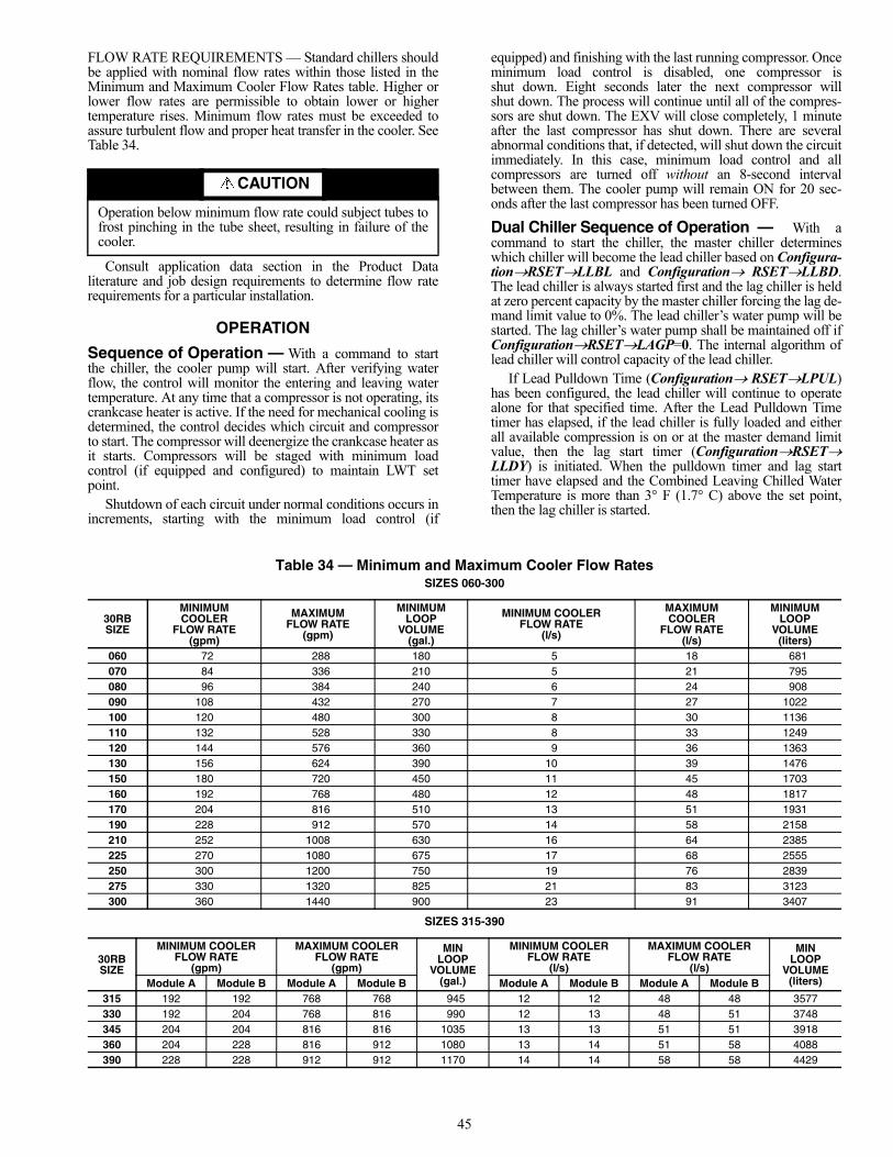
45
FLOW RATE REQUIREMENTS — Standard chillers shouldbe applied with nominal flow rates within those listed in theMinimum and Maximum Cooler Flow Rates table. Higher orlower flow rates are permissible to obtain lower or highertemperature rises. Minimum flow rates must be exceeded toassure turbulent flow and proper heat transfer in the cooler. SeeTable 34.
Consult application data section in the Product Dataliterature and job design requirements to determine flow raterequirements for a particular installation.
OPERATION
Sequence of Operation — With a command to startthe chiller, the cooler pump will start. After verifying waterflow, the control will monitor the entering and leaving watertemperature. At any time that a compressor is not operating, itscrankcase heater is active. If the need for mechanical cooling isdetermined, the control decides which circuit and compressorto start. The compressor will deenergize the crankcase heater asit starts. Compressors will be staged with minimum loadcontrol (if equipped and configured) to maintain LWT setpoint.
Shutdown of each circuit under normal conditions occurs inincrements, starting with the minimum load control (if
equipped) and finishing with the last running compressor. Onceminimum load control is disabled, one compressor isshut down. Eight seconds later the next compressor willshut down. The process will continue until all of the compres-sors are shut down. The EXV will close completely, 1 minuteafter the last compressor has shut down. There are severalabnormal conditions that, if detected, will shut down the circuitimmediately. In this case, minimum load control and allcompressors are turned off without an 8-second intervalbetween them. The cooler pump will remain ON for 20 sec-onds after the last compressor has been turned OFF.
Dual Chiller Sequence of Operation — With acommand to start the chiller, the master chiller determineswhich chiller will become the lead chiller based on Configura-tionRSETLLBL and Configuration RSETLLBD.The lead chiller is always started first and the lag chiller is heldat zero percent capacity by the master chiller forcing the lag de-mand limit value to 0%. The lead chiller’s water pump will bestarted. The lag chiller’s water pump shall be maintained off ifConfigurationRSETLAGP=0. The internal algorithm oflead chiller will control capacity of the lead chiller.
If Lead Pulldown Time (ConfigurationRSETLPUL)has been configured, the lead chiller will continue to operatealone for that specified time. After the Lead Pulldown Timetimer has elapsed, if the lead chiller is fully loaded and eitherall available compression is on or at the master demand limitvalue, then the lag start timer (ConfigurationRSETLLDY) is initiated. When the pulldown timer and lag starttimer have elapsed and the Combined Leaving Chilled WaterTemperature is more than 3° F (1.7° C) above the set point,then the lag chiller is started.
Table 34 — Minimum and Maximum Cooler Flow RatesSIZES 060-300
SIZES 315-390
CAUTION
Operation below minimum flow rate could subject tubes tofrost pinching in the tube sheet, resulting in failure of thecooler.
30RB SIZE
MINIMUM COOLER
FLOW RATE (gpm)
MAXIMUM FLOW RATE
(gpm)
MINIMUM LOOP
VOLUME (gal.)
MINIMUM COOLER FLOW RATE
(l/s)
MAXIMUM COOLER
FLOW RATE (l/s)
MINIMUM LOOP
VOLUME (liters)
060 72 288 180 5 18 681070 84 336 210 5 21 795080 96 384 240 6 24 908090 108 432 270 7 27 1022100 120 480 300 8 30 1136110 132 528 330 8 33 1249120 144 576 360 9 36 1363130 156 624 390 10 39 1476150 180 720 450 11 45 1703160 192 768 480 12 48 1817170 204 816 510 13 51 1931190 228 912 570 14 58 2158210 252 1008 630 16 64 2385225 270 1080 675 17 68 2555250 300 1200 750 19 76 2839275 330 1320 825 21 83 3123300 360 1440 900 23 91 3407
30RB SIZE
MINIMUM COOLER FLOW RATE
(gpm)
MAXIMUM COOLER FLOW RATE
(gpm)
MIN LOOP
VOLUME (gal.)
MINIMUM COOLER FLOW RATE
(l/s)
MAXIMUM COOLER FLOW RATE
(l/s)
MIN LOOP
VOLUME (liters)Module A Module B Module A Module B Module A Module B Module A Module B
315 192 192 768 768 945 12 12 48 48 3577330 192 204 768 816 990 12 13 48 51 3748345 204 204 816 816 1035 13 13 51 51 3918360 204 228 816 912 1080 13 14 51 58 4088390 228 228 912 912 1170 14 14 58 58 4429
46
If the lag chiller’s water pump was not started when the ma-chines went into occupied mode, then the lag chiller waterpump will be started. The lag chiller will start when the masterchiller forcing the lag chiller demand limit value (LAG_LIM)to the master’s demand limit value. If lead/lag capacity balanceis selected, once the lag chiller has started, the master chillerwill try to keep the difference in capacity between lead and lagto less than 20%. The master chiller will then be responsible forwater loop capacity calculation, and will determine whichchiller, the lead or lag, will increase or decrease capacity. Whenthe load reduces, the lag chiller will unload first. To accomplishthis, the lead chiller set point is decreased by 4° F (–2.2° C)until the lag chiller unloads.
To configure the two chillers for dual chiller operation,the master chiller must have the Control Method variable (Op-erating ModeSLCTOPER) set to meet the job require-ments. The slave chiller must be set to Control Method variable(Operating ModeSLCTOPER) = 2 (CCN Control) andthe remote-off-enable switch must be in the enable position.The master chiller and the slave chiller CCN addresses (Con-figurationOPTNCCNA) must be configured. The masterand slave chillers can be addressed from 1 to 239. Each deviceconnected to the network must have its own unique address.Both chillers must have the same CCN Bus Number (Configu-rationOPTNCCNB). Lead/Lag Chiller Enable must beset for both chillers by configuring Master/Slave Select (Con-figurationRSET MSSL) to 1 (Master) for the masterchiller. The slave chiller Master/Slave Select must be set to 2(Slave). The master chiller can be configured to use Lead/LagBalance (ConfigurationRSETLLBL) to rotate the leadand lag chillers after a configured number of hours of opera-tion. The Lag Start Delay (ConfigurationRSETLLBD)can be configured. This prevents the Lag chiller from startinguntil the lead chiller is fully loaded and the delay has elapsed.
Operating ModesMODE 1 (Operating ModeMODEMD01) — StartupDelay in EffectCriteria for Mode — Tested when the unit is started. Thismode is active when the Minutes Off Time (ConfigurationOPTNDELY) timer is active.Action Taken — The unit will not start until the timer hasexpired.Termination — The mode will terminate when the timerexpires.Possible Causes — This mode is in effect only due to the Min-utes Off Time timer.MODE 2 (Operating ModeMODEMD02) — SecondSetpoint in UseCriteria for Mode — Tested when the unit is ON. This modeis active when Cooling Setpoint 2 (SetpointsCOOLCSP.2) or Ice Setpoint (SetpointsCOOLCSP.3) is inuse. While in this mode, the Active Setpoint (Run StatusVIEWSETP) will show the CSP.2 or CSP.3 value.Action Taken — The unit will operate to the Cooling Setpoint2 (CSP.2) or Ice Setpoint (CSP.3).Termination — This mode will terminate when the CoolingSetpoint 2 (CSP.2) or Ice Setpoint (CSP.3) is no longer in use.Possible Causes — This mode is in effect only due to pro-gramming options.MODE 3 (Operating ModeMODEMD03) — Reset inEffectCriteria for Mode — Tested when the unit is ON. This modeis active when Temperature Reset (ConfigurationRSETCRST) is enabled either by CRST=1 (Outside Air Tempera-ture), CRST=2 (Return Water), CRST=3 (4-20 mA Input), orCRST=4 (Space Temperature) and is active.
Action Taken — The Active Setpoint (Run StatusVIEWSETP) will be modified according to the programmedinformation and will be displayed as the Control Point (RunStatusVIEWCTPT).Termination — This mode will terminate when the Tempera-ture Reset is not modifying the active leaving water set point,so SETP is the same as CTPT.Possible Causes — This mode is in effect only due to pro-gramming options.MODE 4 (Operating ModeMODEMD04) — DemandLimit ActiveCriteria for Mode — Tested when the unit is ON. This modeis active when Demand Limit (ConfigurationRSETDMDC) is enabled either by DMDC=1 (Switch), DMDC=2(4-20 mA Input) or the Night Time Low Sound Capacity Limit(ConfigurationOPTN LS.LT).Action Taken — The Active Demand Limit Value (RunStatusVIEWLIM) will display the current demand limitaccording to the programmed information and the unit’s capac-ity will be reduced to the amount shown or lower.Termination — This mode will terminate when the DemandLimit command has been removed.Possible Causes — This mode is in effect when capacity is be-ing limited by the demand limit function.MODE 5 (Operating ModeMODEMD05) — RampLoading ActiveCriteria for Mode — Tested when the unit is ON. This modeis active when Ramp Loading (ConfigurationOPTNRL.S) is enabled and the following conditions are met:
1. The leaving water temperature is more than 4° F (2.2° C)from the Control Point (Run StatusVIEWCTPT),and
2. The rate of change of the leaving water temperature isgreater than the Cool Ramp Loading (SetPointsCOOLCRMP).
Action Taken — The control will limit the capacity stepincrease until one of the two conditions in Mode 5 is no longertrue.Termination — This mode will terminate once both conditionsin Mode 5 are no longer true.Possible Causes — This mode is in effect only when capacityis being limited by the ramp loading function.MODE 6 (Operating ModeMODEMD06) — CoolerHeater ActiveCriteria for Mode — Tested when unit is ON or OFF. Thismode is active when the cooler heater is energized, if theOutdoor Air Temperature (TemperatureUNITOAT) isless than the calculated value (Freeze Setpoint + Cooler HeaterDelta T Setpoint [ConfigurationSERVHTR] default– 2° F [1.1° C]), and either the Leaving Water Temperature(TemperatureUNITLWT) or the Entering Water Temper-ature (TemperatureUNITEWT) are less than or equal tothe Freeze Setpoint + Cooler Heater Delta T Setpoint (HTR).
The Freeze Setpoint is 34 F (1.1 C) for fresh water systems(ConfigurationSERVFLUD=1). The Freeze Setpoint isthe Brine Freeze Setpoint (ConfigurationSERVLOSP)for Medium Temperature Brine systems (ConfigurationSERVFLUD=2).Action Taken — The cooler heater will be energized.Termination — The cooler heater will be deenergized whenboth the Entering Water Temperature (EWT) and LeavingWater Temperature (LWT) are above the Freeze Setpoint +Cooler Heater Delta T Setpoint (HTR).Possible Causes — This mode will be enabled for freeze pro-tection. If the temperatures are not as described above, check
47
the accuracy of the outside air, entering and leaving waterthermistors.MODE 7 (Operating ModeMODEMD07) — WaterPump RotationCriteria for Mode — Tested when the unit is ON or OFF. Thismode is active when the Cooler Pump Sequence (Configura-tionOPTNPUMP) =2 (2 Pumps Automatic Changeover)and the Pump Rotation Delta Timer (ConfigurationOPTNROT.P) has expired.Action Taken — The control will switch the operation of thepumps. The lead pump will be operating normally. The lagpump will be started, becoming the lead, and then the originallead pump will be shut down.Termination — This mode will terminate when the pumpoperation has been completed.Possible Causes — This mode is in effect only due to pro-gramming options.MODE 8 (Operating ModeMODEMD08) — Pump Pe-riodic StartCriteria for Mode — This mode is active when the coolerpump is started for the Periodic Pump Start configuration(ConfigurationOPTNPM.PS=YES).Action Taken — If the pump has not run that day, a pump willbe started and will run for 2 seconds at 2:00 PM. If the machineis equipped with dual pumps, Pump no. 1 will run on even days(such as day 2, 4, 6 of the month). Pump no. 2 will run on odddays (such as day 1, 3, 5 of the month).Termination — This mode will terminate when the pumpshuts down.Possible Causes — This mode is in effect only due to pro-gramming options.MODE 9 (Operating ModeMODEMD09) — NightLow Noise ActiveCriteria for Mode — This mode is active when the NightTime Low Noise Option has been configured and the time iswithin the configured time. Programming a Night Low NoiseStart Time (ConfigurationOPTNLS.ST) and a NightLow Noise End Time (ConfigurationOPTNLS.ND) con-figures the option.Action Taken — The control will raise the head pressure setpoint to reduce the number of condenser fans on, therebyreducing the sound of the machine. Additionally, if the NightTime Low Sound Capacity Limit (ConfigurationOPTNLS.LT) has been configured, the units capacity will be limit-ed to the programmed level.Termination — This mode will terminate once the Night LowNoise End Time (LS.ND) has been reached.Possible Causes — This mode is in effect only due to pro-gramming options.MODE 10 (Operating ModeMODEMD10) — SystemManager ActiveCriteria for Mode — Tested when the unit is ON or OFF. Thismode is active if a System Manager such as Building Supervi-sor, Chillervisor System Manager, or another CCN device iscontrolling the machine.Action Taken — The machine will respond to the specificcommand received from the System Manager.Termination — The mode will be terminated if the SystemManager control is released.Possible Causes — This mode is in effect only due to pro-gramming options.MODE 11 (Operating ModeMODEMD11) — MastSlave Ctrl ActiveCriteria for Mode — Tested if the machine is ON. This modeis active if the Master Slave Control has been enabled. Having
2 machines programmed, one as the master (ConfigurationRSETMSSL=1 [Master]) and the other as a slave(ConfigurationRSETMSSL=2 [Slave]).Action Taken — Both the master and slave machine will re-spond to the capacity control commands issued by the mastercontroller. This may include control point changes and demandlimit commands.Termination — This mode will terminate when the MasterSlave Control has been disabled.Possible Causes — This mode is in effect only due to pro-gramming options.MODE 12 (Operating ModeMODEMD12) — AutoChangeover ActiveCriteria for Mode — This mode is not supported for CoolingOnly units.Action Taken — None.Termination — None.Possible Causes — This mode is in effect only due to pro-gramming options.MODE 13 (Operating ModeMODEMD13) — FreeCooling ActiveCriteria for Mode — This mode is not supported for CoolingOnly units.Action Taken — None.Termination — None.Possible Causes — This mode is in effect only due to pro-gramming options.MODE 14 (Operating ModeMODEMD14) — Re-claim ActiveCriteria for Mode — This mode is not supported for CoolingOnly units.Action Taken — None.Termination — None.Possible Causes — This mode is in effect only due to pro-gramming options.MODE 15 (Operating ModeMODEMD15) — ElectricHeat ActiveCriteria for Mode — This mode is not supported for CoolingOnly units.Action Taken — None.Termination — None.Possible Causes — This mode is in effect only due to pro-gramming options.MODE 16 (Operating ModeMODEMD16) — HeatingLow EWT LockoutCriteria for Mode — This mode is not supported for CoolingOnly units.Action Taken — None.Termination — None.Possible Causes — This mode is in effect only due to pro-gramming options.MODE 17 (Operating ModeMODEMD17) — BoilerActiveCriteria for Mode — This mode is not supported for CoolingOnly units.Action Taken — None.Termination — None.Possible Causes — This mode is in effect only due to pro-gramming options.MODE 18 (Operating ModeMODEMD18) — IceMode in Effect
48
Criteria for Mode — Tested when the unit is ON. This modeis active when Ice Setpoint (SetpointsCOOLCSP.3) isin use. While in this mode, the Active Setpoint (Run StatusVIEWSETP) will show the CSP.3 value.Action Taken — The unit will operate to the Ice Setpoint(CSP.3).Termination — This mode will terminate when the Ice Set-point (CSP.3) is no longer in use.Possible Causes — This mode is in effect only due to pro-gramming options.MODE 19 Operating ModeMODEMD19) — DefrostActive on Cir AMODE 20 (Operating ModeMODEMD20) — DefrostActive on Cir BCriteria for Mode — This mode is not supported for CoolingOnly units.Action Taken — None.Termination — None.Possible Causes — This mode is in effect only due to pro-gramming options.MODE 21 (Operating ModeMODEMD21) — LowSuction Circuit AMODE 22 (Operating ModeMODEMD22) — LowSuction Circuit BMODE 23 (Operating ModeMODEMD23) — LowSuction Circuit CCriteria for Mode — The criteria are tested when the circuit isON. The appropriate circuit mode will be active if one of thefollowing conditions is true:
1. If the circuit’s Saturated Suction Temperature (SST) ismore than 6° F (3.3° C) less than the freeze point andboth the cooler approach (Leaving Water Temperature-SST) and superheat (Suction Gas Temperature – SST) aregreater than 15° F (8.3° C).
2. If there is more than 1 compressor ON in the circuit andthe circuit’s SST is greater than 18° F (10.0° C) below thefreeze point for more than 90 seconds.
3. If there is more than 1 compressor ON in the circuit andthe circuit’s SST is greater than –4° F (–20.0° C) and theSST 30 seconds ago was 18° F (10.0° C) below the freezepoint.
4. If the circuit’s saturated suction temperature is greaterthan 6° F (3.3° C) below the freeze point for more than3 minutes.
For a fresh water system (ConfigurationSERVFLUD=1), the freeze point is 34° F (1.1° C). For medium temperaturebrine systems, (ConfigurationSERVFLUD=2), the freezepoint is Brine Freeze Set Point (ConfigurationSERVLOSP).Action Taken — For criterion 1, no additional stages will beadded. For criteria 2, 3 and 4, one stage of capacity will beremoved.Termination — The mode will terminate when the circuit’sSaturated Suction Temperature is greater than the freeze pointminus 6° F (3.3° C) or the circuit has alarmed.Possible Causes — If this condition is encountered, see Possi-ble Causes for Alarms P.05, P.06, and P.07 on page 67.MODE 24 (Operating ModeMODEMD24) — HighDGT Circuit AMODE 25 (Operating ModeMODEMD25) — HighDGT Circuit BMODE 26 (Operating ModeMODEMD26) — HighDGT Circuit C
Criteria for Mode — This mode is tested for when any circuitis running. The circuit saturated condensing and suction tem-peratures are monitored to ensure that the compressors alwaysoperate withing their allowed “map.” Operation at conditionsat or outside the “map” boundaries will cause this mode to bein effect. Operation at extremely low suction pressures andhigh condensing temperatures will cause the mode to begenerated.Action Taken — The circuit will not be allowed to increase ca-pacity and may be automatically unloaded or stopped.Termination — This mode will terminate when or if the circuitrefrigerant conditions return to within the compressor “map.”Possible Causes — This mode could be in effect due to a lowfluid flow rate, overcharge of oil in a circuit, dirty condensercoils, refrigerant overcharge, or excessive brine concentration.MODE 27 (Operating ModeMODEMD27) — HighPres Override Cir AMODE 28 (Operating ModeMODEMD28) — HighPres Override Cir BMODE 29 (Operating ModeMODEMD29) — HighPres Override Cir CCriteria for Mode — Tested when the circuit is ON. Theappropriate circuit mode will be active if the discharge pressurefor the circuit, Discharge Pressure Circuit A (PressurePRC.ADP.A), Discharge Pressure Circuit B (Pres-surePRC.BDP.B), or Discharge Pressure Circuit C(PressurePRC.CDP.C) is greater than the High PressureThreshold (ConfigurationSERVHP.TH).Action Taken — The capacity of the affected circuit will bereduced. If the unit is equipped with Minimum Load Controland has been configured for High Ambient (ConfigurationUNITHGBP=3), the minimum load control valve will beenergized. Two minutes following the capacity reduction, thecircuit’s saturated condensing temperature (SCT) is calculatedand stored. The affected circuit will not be allowed to add ca-pacity for at least 5 minutes following the capacity reduction. Ifafter 5 minutes, the circuit’s saturated condensing temperatureis less than SCT – 3° F (1.7° C), if required, another stage ofcapacity will be added.
If additional steps of capacity are required, the control willlook for other circuits to add capacity.Termination — This mode will terminate once the circuit’ssaturated condensing temperature is less than SCT – 3° F(1.7° C).Possible Causes — If this condition is encountered, see Possi-ble Causes for Alarm A1.03. on page 64.MODE 30 (Operating ModeMODEMD30) — LowSuperheat Circuit AMODE 31 (Operating ModeMODEMD31) — LowSuperheat Circuit BMODE 32 (Operating ModeMODEMD32) — LowSuperheat Circuit CCriteria for Mode — Tested when the circuit is ON with atleast 1 compressor ON. The appropriate circuit mode will beactive is the circuit’s superheat is less than 5° F (2.8° C).Action Taken — No additional stages of circuit capacity willbe added until the circuit’s superheat is greater than 5° F(2.8° C).
The control will look for other circuits to add capacity ifadditional steps of capacity are required.Termination — This mode will terminate once the affectedcircuit’s superheat is greater than 5° F (2.8° C).Possible Causes — If this condition is encountered, see Possi-ble Causes for Alarms P.11, P.12 and P.13 on page 67.
49
Optional Heat Reclaim Module — For chillers withthe heat reclaim option, Configuration→UNIT→RECLshould be set to YES from the factory.
This option requires the installation of an additional board.This is the same board as used for energy management module(EMM).
This board allows control of:• a heat reclaim condenser pump• a heat reclaim condenser heater• solenoid valves to shut off the normal cooling coil (one,
two or three for each circuit, depending on the unit size)• two solenoid drain valves for the heat reclaim coil (one
for each circuit)• two solenoid valves to shut off the water condenser (one
for each circuit)• two solenoid drain valves for the water condenser (one
for each circuit).For more control details, refer to the unit low voltage con-
trol schematic.Selecting the heat reclaim mode can be done with either the
local interface or remotely with the (RECL_SW) contact or byCCN. For remote connection, Position 14 and 15 on terminalblock 7 should be used to switch to air cooled (open) or heat re-claim mode (closed). The RECL_SW contact can be accessedthrough (Input→GEN.I→RECL).
In local mode, the reclaim select must be set to “SwitchControl” (Operating mode→RL.SE = Switch Ctrl).
In CCN mode, the reclaim select must be set to YES (Oper-ating mode→RL.SE = YES).
The heat reclaim function becomes active when the heat re-claim entering water temperature is lower than the heat reclaimsetpoint (Setpoints→MISC→RSP), minus half or quarter ofthe heat reclaim dead band (Setpoints→MISC→RDB). Thedefault heat reclaim dead band is 8° F and the recommendeddead band range is 5 to 20° F.
The difference between the reclaim entering water tempera-ture and reclaim set point will determine if one or two circuitsare required to provide heat reclaim capacity. See Table 35 fordetails.
Table 35 — Heat Reclaim Circuits
The heat reclaim function is not active when the heat re-claim entering water temperature is higher than the heat re-claim set point, plus half of the heat reclaim dead band.
Heat reclaim active mode is indicated by MODE_14 = 1.Mode_14 can be accessed through CCN.
The following is the changeover procedure from coolingmode to heat reclaim mode. First is the start-up of the condens-er pump. Then, verification of the condenser flow switch con-trol contact. If this remains open after one minute of condenserpump operation, the circuit remains in cooling mode and analarm will be activated. The control will then wait until the dif-ference between saturated condensing temperature and saturat-ed suction temperature is higher than 10° F. When this occurs,the pumpdown sequence is activated.
During pumpdown, the control will open the water con-denser inlet valve and close the air condenser air valves
3 seconds later. After one minute or when the subcooling valueis above 13.2° F, the heat reclaim operation is effective.
Heat reclaim entering water temperature (HEWT), leavingwater temperature (HLWT), heat reclaim pump hours(HR.CD), refrigerant sub-cooling (hr_subcx) can be can beaccessed through following paths:
Temperature→HEWTTemperature→HLWTRun Status→RUN→HR.CDTemperature→CIR.A→HRS.ATemperature→CIR.B→HRS.B
RECLAIM CONDENSER WATER VALVE OUTPUT —This output (0 to 10 Vdc) is used to control heat reclaim con-denser 3-way water valve position through a variable speeddevice.
The 3-way valve should be installed to facilitate the coldwater start-up (below 59 F) and maintain a stable head pressurecontrol during heat reclaim operation. The minimum positionof the water valve should be set at 20% and maximum positionshould be set at 100%.
When the entering water temperature is below 68 F, the wa-ter valve should remain at 20% position to allow a maximumre-circulating of the warm water between the 3-way watervalve and heat reclaim condenser.
When the entering water temperature is above 104 F, thewater valve will remain fully open, allowing no recirculation ofthe warm water.
When the entering water temperature is between 68 F and104 F, the water valve will be adjusted between 20% and 100%position in linear proportion to the value of the entering watertemperature.
SERVICE
Electronic Expansion Valve (EXV) — See Fig. 25for a cutaway view of the EXV. High-pressure liquid refriger-ant enters valve through the top. As refrigerant passes throughthe orifice, pressure drops and refrigerant changes to a 2-phasecondition (liquid and vapor). The electronic expansion valveoperates through an electronically controlled activation of astepper motor. The stepper motor stays in position, unlesspower pulses initiate the two discrete sets of motor stator wind-ings for rotation in either direction. The direction depends onthe phase relationship of the power pulses.
The motor directly operates the spindle, which has rotatingmovements that are transformed into linear motion by thetransmission in the cage assembly. The valve cone is a V-porttype which includes a positive shut-off when closed.
There are two different EXVs. For circuits with 1 or 2 com-pressors, the total number of steps is 2785. For circuits with 3or 4 compressors, the total number of steps is 3690. The EXVmotor moves at 150 steps per second. Commanding the valveto either 0% or 100% will add extra 160 steps to the move, toensure the value is open or closed completely.
The EXV board controls the valve. Each circuit has athermistor located in a well in the suction manifold before thecompressor. Suction pressure as measured by the suction pres-sure transducer is converted to a saturated suction temperature.The thermistor measures the temperature of the superheatedgas entering the compressor and the pressure transducer deter-mines the saturated temperature of suction gas. The differencebetween the temperature of the superheated gas and thesaturated suction temperature is the superheat. The EXV boardcontrols the position of the electronic expansion valve steppermotor to maintain superheat set point.
HEAT RECLAIMENTERING
WATERTEMPERATURE
NO. OF CIRCUITS IN RECLAIM
START UP hr_ewt>rsp+hr_deadb/4
hr_ewt>rsp+hr_deadb/2
hr_ewt < rsp-hr_deadb/2 Two One Zero
rsp-hr_deadb/2<hr_ewt < rsp-
hr_deadb/4One One Zero
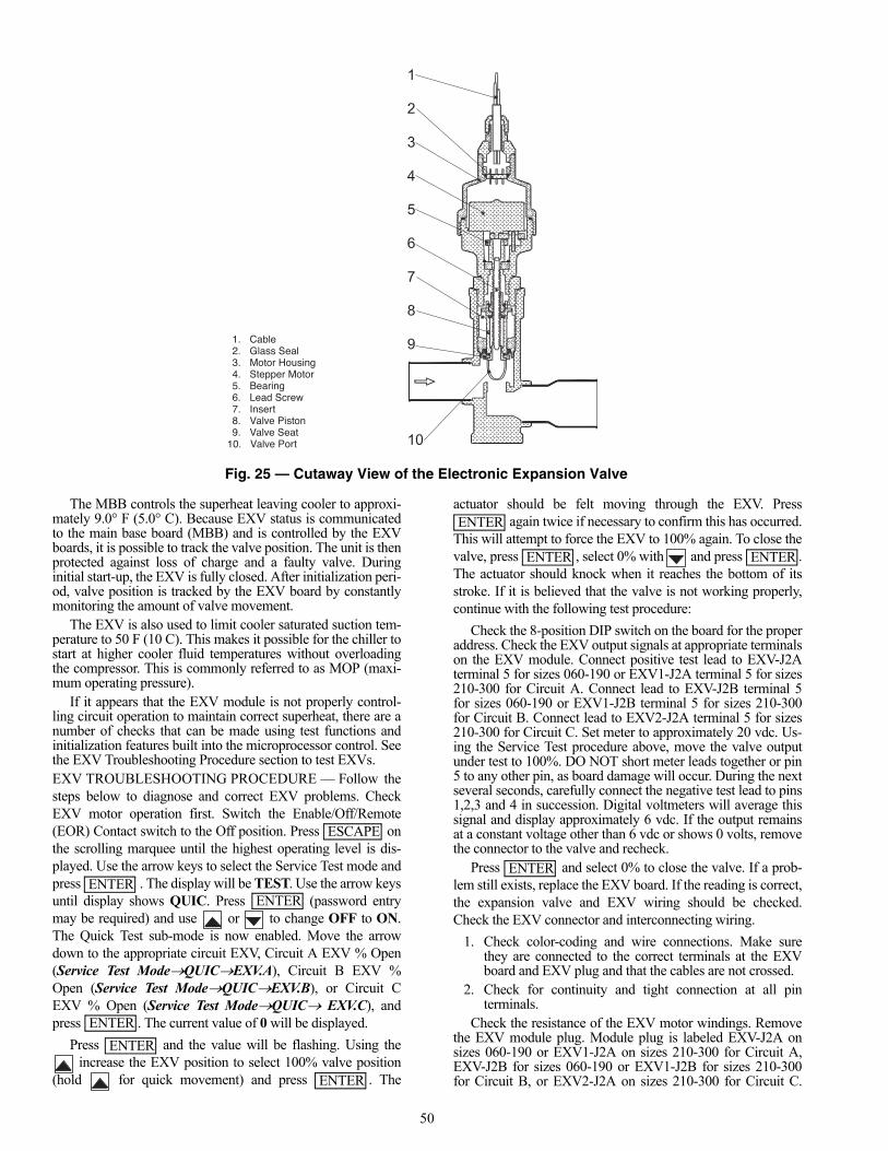
50
The MBB controls the superheat leaving cooler to approxi-mately 9.0° F (5.0° C). Because EXV status is communicatedto the main base board (MBB) and is controlled by the EXVboards, it is possible to track the valve position. The unit is thenprotected against loss of charge and a faulty valve. Duringinitial start-up, the EXV is fully closed. After initialization peri-od, valve position is tracked by the EXV board by constantlymonitoring the amount of valve movement.
The EXV is also used to limit cooler saturated suction tem-perature to 50 F (10 C). This makes it possible for the chiller tostart at higher cooler fluid temperatures without overloadingthe compressor. This is commonly referred to as MOP (maxi-mum operating pressure).
If it appears that the EXV module is not properly control-ling circuit operation to maintain correct superheat, there are anumber of checks that can be made using test functions andinitialization features built into the microprocessor control. Seethe EXV Troubleshooting Procedure section to test EXVs.EXV TROUBLESHOOTING PROCEDURE — Follow thesteps below to diagnose and correct EXV problems. CheckEXV motor operation first. Switch the Enable/Off/Remote(EOR) Contact switch to the Off position. Press onthe scrolling marquee until the highest operating level is dis-played. Use the arrow keys to select the Service Test mode andpress . The display will be TEST. Use the arrow keysuntil display shows QUIC. Press (password entrymay be required) and use or to change OFF to ON.The Quick Test sub-mode is now enabled. Move the arrowdown to the appropriate circuit EXV, Circuit A EXV % Open(Service Test ModeQUICEXV.A), Circuit B EXV %Open (Service Test ModeQUICEXV.B), or Circuit CEXV % Open (Service Test ModeQUIC EXV.C), andpress . The current value of 0 will be displayed.
Press and the value will be flashing. Using the increase the EXV position to select 100% valve position
(hold for quick movement) and press . The
actuator should be felt moving through the EXV. Press again twice if necessary to confirm this has occurred.
This will attempt to force the EXV to 100% again. To close thevalve, press , select 0% with and press .The actuator should knock when it reaches the bottom of itsstroke. If it is believed that the valve is not working properly,continue with the following test procedure:
Check the 8-position DIP switch on the board for the properaddress. Check the EXV output signals at appropriate terminalson the EXV module. Connect positive test lead to EXV-J2Aterminal 5 for sizes 060-190 or EXV1-J2A terminal 5 for sizes210-300 for Circuit A. Connect lead to EXV-J2B terminal 5for sizes 060-190 or EXV1-J2B terminal 5 for sizes 210-300for Circuit B. Connect lead to EXV2-J2A terminal 5 for sizes210-300 for Circuit C. Set meter to approximately 20 vdc. Us-ing the Service Test procedure above, move the valve outputunder test to 100%. DO NOT short meter leads together or pin5 to any other pin, as board damage will occur. During the nextseveral seconds, carefully connect the negative test lead to pins1,2,3 and 4 in succession. Digital voltmeters will average thissignal and display approximately 6 vdc. If the output remainsat a constant voltage other than 6 vdc or shows 0 volts, removethe connector to the valve and recheck.
Press and select 0% to close the valve. If a prob-lem still exists, replace the EXV board. If the reading is correct,the expansion valve and EXV wiring should be checked.Check the EXV connector and interconnecting wiring.
1. Check color-coding and wire connections. Make surethey are connected to the correct terminals at the EXVboard and EXV plug and that the cables are not crossed.
2. Check for continuity and tight connection at all pinterminals.
Check the resistance of the EXV motor windings. Removethe EXV module plug. Module plug is labeled EXV-J2A onsizes 060-190 or EXV1-J2A on sizes 210-300 for Circuit A,EXV-J2B for sizes 060-190 or EXV1-J2B for sizes 210-300for Circuit B, or EXV2-J2A on sizes 210-300 for Circuit C.
1. Cable 2. Glass Seal 3. Motor Housing 4. Stepper Motor 5. Bearing 6. Lead Screw 7. Insert 8. Valve Piston 9. Valve Seat 10. Valve Port
Fig. 25 — Cutaway View of the Electronic Expansion Valve
ESCAPE
ENTERENTER
ENTER
ENTER
ENTER
ENTER
ENTER ENTER
ENTER
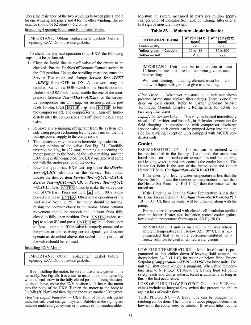
51
Check the resistance of the two windings between pins 1 and 3for one winding and pins 2 and 4 for the other winding. The re-sistance should be 52 ohms (± 5.2 ohms).Inspecting/Opening Electronic Expansion Valves
To check the physical operation of an EXV, the followingsteps must be performed.
1. Close the liquid line shut off valve of the circuit to bechecked. Put the Enable/Off/Remote Contact switch inthe Off position. Using the scrolling marquee, enter theService Test mode and change Service TestTESTT.REQ from OFF to ON. A password may berequired. Switch the EOR switch to the Enable position.Under the COMP sub-mode, enable the one of the com-pressors (Service TestTESTCP.xn) for the circuit.Let compressor run until gage on suction pressure portreads 10 psig. Press , and to turnthe compressor off. The compressor will turn off. Imme-diately after the compressor shuts off, close the dischargevalve.
2. Remove any remaining refrigerant from the system lowside using proper reclaiming techniques. Turn off the linevoltage power supply to the compressors.
3. The expansion valve motor is hermetically sealed insidethe top portion of the valve. See Fig. 24. Carefullyunscrew the 11/16 in. (27 mm) retaining nut securing themotor portion to the body of the valve making sure theEXV plug is still connected. The EXV operator will comeout with the motor portion of the device.
4. Enter the appropriate EXV test step under the (ServiceTestQUIC) sub-mode in the Service Test mode.Locate the desired item Service TestQUICEXV.A,Service TestQUICEXV.B, or Service TestQUICEXV.C. Press twice to make the valve posi-tion of 0% flash. Press and hold until 100% is dis-played and press . Observe the operation of thelead screw. See Fig. 25. The motor should be turning,raising the operator closer to the motor. Motor actuatormovement should be smooth and uniform from fullyclosed to fully open position. Press twice, use
to select 0% and press again to check opento closed operation. If the valve is properly connected tothe processor and receiving correct signals, yet does notoperate as described above, the sealed motor portion ofthe valve should be replaced.
Installing EXV Motor
If re-installing the motor, be sure to use a new gasket in theassembly. See Fig. 26. It is easier to install the motor assemblywith the lead screw in the fully closed position. Using the stepsoutlined above, move the EXV position to 0. Insert the motorinto the body of the EXV. Tighten the motor to the body to36 ft-lb (50 N-m) and then tighten the valve another 30 degrees.Moisture Liquid Indicator — Clear flow of liquid refrigerantindicates sufficient charge in system. Bubbles in the sight glassindicate undercharged system or presence of noncondensables.
Moisture in system measured in parts per million (ppm),changes color of indicator. See Table 36. Change filter drier atfirst sign of moisture in system.
Table 36 — Moisture Liquid Indicator
Filter Drier — Whenever moisture-liquid indicator showspresence of moisture, replace filter drier(s). There is one filterdrier on each circuit. Refer to Carrier Standard ServiceTechniques Manual, Chapter 1, Refrigerants, for details onservicing filter driers.Liquid Line Service Valve — This valve is located immediatelyahead of filter drier, and has a 1/4-in. Schrader connection forfield charging. In combination with compressor dischargeservice valve, each circuit can be pumped down into the highside for servicing except on units equipped with MCHX con-denser coils.
CoolerFREEZE PROTECTION — Coolers can be ordered withheaters installed in the factory. If equipped, the main baseboard based on the outdoor-air temperature and the enteringand leaving water thermistors controls the cooler heaters. TheHeater Set Point is the sum of the freeze point and CoolerHeater DT Setp (ConfigurationSERVHTR).
If the entering or leaving water temperature is less than theHeater Set Point and the outdoor air temperature is less thanthe Heater Set Point – 2° F (1.1° C), then the heater will beturned on.
If the Entering or Leaving Water Temperature is less thanthe Brine Freeze Setpoint (ConfigurationSERVLOSP) +1.0° F (0.5° C), then the heater will be turned on along with thepump.
Entire cooler is covered with closed-cell insulation appliedover the heater. Heater plus insulation protect cooler againstlow ambient temperature freeze-up to –20 F (–28 C).
LOW FLUID TEMPERATURE — Main base board is pro-grammed to shut chiller down if leaving fluid temperaturedrops below 34 F (1.1 C) for water or below Brine FreezeSetpoint (ConfigurationSERVLOSP) for brine units. Theunit will shut down without a pumpout. When fluid tempera-ture rises to 6° F (3.3° C) above the leaving fluid set point,safety resets and chiller restarts. Reset is automatic as long asthis is the first occurrence.LOSS OF FLUID FLOW PROTECTION — All 30RB ma-chines include an integral flow switch that protects the chilleragainst loss of cooler flow.TUBE PLUGGING — A leaky tube can be plugged untilretubing can be done. The number of tubes plugged determineshow soon the cooler must be retubed. If several tubes require
IMPORTANT: Obtain replacement gaskets beforeopening EXV. Do not re-use gaskets.
IMPORTANT: Obtain replacement gasket beforeopening EXV. Do not re-use gaskets.
ENTER ENTER
ENTER
ENTER
ENTERENTER
REFRIGERANT R-410A AT 75 F (24 C) (ppm)
AT 125 F (52 C) (ppm)
Green — Dry <20 <60Yellow-green — Caution 20 to 165 60 to 500Yellow — Wet >165 >500
IMPORTANT: Unit must be in operation at least12 hours before moisture indicator can give an accu-rate reading.
With unit running, indicating element must be in con-tact with liquid refrigerant to give true reading.
IMPORTANT: If unit is installed in an area whereambient temperatures fall below 32 F (0° C), it is rec-ommended that a suitable corrosion-inhibited anti-freeze solution be used in chilled water circuit.
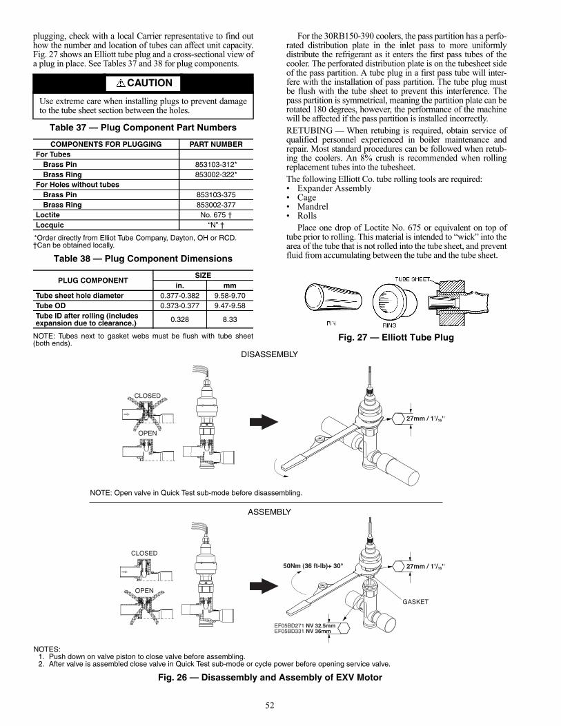
52
plugging, check with a local Carrier representative to find outhow the number and location of tubes can affect unit capacity.Fig. 27 shows an Elliott tube plug and a cross-sectional view ofa plug in place. See Tables 37 and 38 for plug components.
Table 37 — Plug Component Part Numbers
*Order directly from Elliot Tube Company, Dayton, OH or RCD.†Can be obtained locally.
Table 38 — Plug Component Dimensions
NOTE: Tubes next to gasket webs must be flush with tube sheet(both ends).
For the 30RB150-390 coolers, the pass partition has a perfo-rated distribution plate in the inlet pass to more uniformlydistribute the refrigerant as it enters the first pass tubes of thecooler. The perforated distribution plate is on the tubesheet sideof the pass partition. A tube plug in a first pass tube will inter-fere with the installation of pass partition. The tube plug mustbe flush with the tube sheet to prevent this interference. Thepass partition is symmetrical, meaning the partition plate can berotated 180 degrees, however, the performance of the machinewill be affected if the pass partition is installed incorrectly.RETUBING — When retubing is required, obtain service ofqualified personnel experienced in boiler maintenance andrepair. Most standard procedures can be followed when retub-ing the coolers. An 8% crush is recommended when rollingreplacement tubes into the tubesheet.The following Elliott Co. tube rolling tools are required: • Expander Assembly• Cage • Mandrel• Rolls
Place one drop of Loctite No. 675 or equivalent on top oftube prior to rolling. This material is intended to “wick” into thearea of the tube that is not rolled into the tube sheet, and preventfluid from accumulating between the tube and the tube sheet.
CAUTION
Use extreme care when installing plugs to prevent damageto the tube sheet section between the holes.
COMPONENTS FOR PLUGGING PART NUMBERFor Tubes
Brass Pin 853103-312*Brass Ring 853002-322*
For Holes without tubesBrass Pin 853103-375Brass Ring 853002-377
Loctite No. 675 †Locquic “N” †
PLUG COMPONENTSIZE
in. mmTube sheet hole diameter 0.377-0.382 9.58-9.70Tube OD 0.373-0.377 9.47-9.58Tube ID after rolling (includes expansion due to clearance.) 0.328 8.33
Fig. 27 — Elliott Tube Plug
CLOSED
OPEN
CLOSED
OPEN
GASKET
OPEN VALVE IN QUICK TEST SUB-MODE BEFORE DISASSEMBLING
EF05BD271 NV 32.5mmEF05BD331 NV 36mm
50Nm (36 ft-lb)+ 30° 27mm / 11/16''
27mm / 11/16''
DISASSEMBLY
ASSEMBLY
NOTES:1. Push down on valve piston to close valve before assembling.2. After valve is assembled close valve in Quick Test sub-mode or cycle power before opening service valve.
Fig. 26 — Disassembly and Assembly of EXV Motor
NOTE: Open valve in Quick Test sub-mode before disassembling.
53
TIGHTENING COOLER HEAD BOLTS (Fig. 28-32)Gasket Preparation — When reassembling cooler heads, al-ways use new gaskets. Gaskets are neoprene-based and arebrushed with a light film of compressor oil. Do not soak gasketor gasket deterioration will result. Use new gaskets within30 minutes to prevent deterioration. Reassemble cooler nozzleend or plain end cover of the cooler with the gaskets. Torque allcooler bolts to the following specification and sequence:5/8-in. Diameter Perimeter Bolts (Grade 5). . . . 150 to 170 ft-lb
(201 to 228 N-m)1/2-in. Diameter Flange Bolts (Grade 5) . . . . . . . . 70 to 90 ft-lb
(94 to 121 N-m)1/2-in. Diameter Center Stud (Grade 5). . . . . . . . . 70 to 90 ft-lb
(94 to 121 N-m)1. Install all bolts finger tight, except for the suction flange
bolts. Installing these flanges will interfere with tighten-ing the center stud nuts.
2. Bolt tightening sequence is outlined in Fig. 27-31. Followthe numbering or lettering sequence so that pressure isevenly applied to gasket.
3. Apply torque in one-third steps until required torque isreached. Load all bolts to each one-third step before pro-ceeding to next one-third step.
4. No less than one hour later, retighten all bolts to requiredtorque values.
5. After refrigerant is restored to system, check for refriger-ant leaks using recommended industry practices.
6. Replace cooler insulation.CHILLED WATER FLOW SWITCH — A factory-installedflow switch is installed in the cooler nozzle for all machines.This is a thermal-dispersion flow switch with no field adjust-ments. The switch is set for approximately 0.5 ft/sec flow. SeeTable 39 for unit flow rate information.
Table 39 — Unit Flow Rates
The sensor tip houses two thermistors and a heater element.One thermistor is located in the sensor tip, closest to the flow-ing fluid. This thermistor is used to detect changes in the flowvelocity of the liquid. The second thermistor is bonded to thecylindrical wall and is affected only by changes in the tempera-ture of the liquid. The thermistors are positioned to be in closecontact with the wall of the sensor probe and, at the same time,to be kept separated from each other within the confines of theprobe.
In order to sense flow, it is necessary to heat one of thethermistors in the probe. When power is applied, the tip of theprobe is heated. As the fluid starts to flow, heat will be carriedaway from the sensor tip. Cooling of the first thermistor is afunction of how fast heat is conducted away by the flowing liq-uid. The difference in temperature between the two thermistorsprovides a measurement of fluid velocity past the sensor probe.When fluid velocity is high, more heat will be carried awayfrom the heated thermistor and the temperature differential willbe small. As fluid velocity decreases, less heat will be taken
from the heated thermistor and there will be an increase in tem-perature differential.
When unit flow rate is above the minimum flow rate, thenthe output is switched on, sending 24 vac through a 560 ohmdropping resistor. This provides 12 vac to the MBB to proveflow has been established.
For recommended maintenance, check the sensor tip forbuild-up every 6 months. Clean the tip with a soft cloth. If nec-essary, build-up (e.g., lime) can be removed with a commonvinegar cleansing agent.
RTPF (Round Tube Plate Fin) Condenser CoilMaintenance and Cleaning Recommenda-tions — Routine cleaning of coil surfaces is essential tomaintain proper operation of the unit. Elimination of contami-nation and removal of harmful residues will greatly increasethe life of the coil and extend the life of the unit. The followingmaintenance and cleaning procedures are recommended as partof the routine maintenance activities to extend the life of thecoil.REMOVE SURFACE LOADED FIBERS — Surface load-ed fibers or dirt should be removed with a vacuum cleaner. If avacuum cleaner is not available, a soft non-metallic bristlebrush may be used. In either case, the tool should be applied inthe direction of the fins. Coil surfaces can be easily damaged(fin edges can be easily bent over and damage to the coating ofa protected coil) if the tool is applied across the fins.NOTE: Use of a water stream, such as a garden hose, against asurface loaded coil will drive the fibers and dirt into the coil.This will make cleaning efforts more difficult. Surface loadedfibers must be completely removed prior to using low velocityclean water rinse.PERIODIC CLEAN WATER RINSE — A periodic cleanwater rinse is very beneficial for coils that are applied in coastalor industrial environments. However, it is very important thatthe water rinse is made with very low velocity water stream toavoid damaging the fin edges. Monthly cleaning as describedbelow is recommended.ROUTINE CLEANING OF COIL SURFACES — Month-ly cleaning with Totaline® environmentally sound coil cleaneris essential to extend the life of coils. This cleaner is availablefrom Carrier Replacement parts division as part numberP902-0301 for a one gallon container, and part numberP902-0305 for a 5 gallon container. It is recommended that allcoils, including the standard copper tube aluminum fin, pre-coated fin, copper fin, or E-coated coils be cleaned with the To-taline environmentally sound coil cleaner as described below.Coil cleaning should be part of the unit’s regularly scheduledmaintenance procedures to ensure long life of the coil. Failureto clean the coils may result in reduced durability in the envi-ronment.Avoid the use of:• coil brighteners• acid cleaning prior to painting• high pressure washers• poor quality water for cleaning
Totaline environmentally sound coil cleaner is non-flamma-ble, hypoallergenic, nonbacterial, and a USDA accepted biode-gradable agent that will not harm the coil or surroundingcomponents such as electrical wiring, painted metal surfaces,or insulation. Use of non-recommended coil cleaners is strong-ly discouraged since coil and unit durability could be affected.
UNIT SIZE30RB
COOLERCONNECTION
SIZE (in.)
MINIMUMFLOW - WATER
(GPM)
MINIMUMFLOW - 40% EG
(GPM)
060-100 4 20 53
110-300 6 44 117
315-390 6 44 (per module) 117 (per module)

54
4 812
16
20
24
2319
1511
5 7
27
913
1721
25
26
2218
1410
6
2
3
1
48
1216
2024
2319
1511
5 7
27
913
17
21
25
26
22
1814
106
2
3
1
1
2
4
3
5
610
1317
21
25
28
24
20
1612
971114
18
22
26
29
27
23
1915
8
1
2
4
3
5
610
1317
21
25
28
24
20
1612
971114
18
22
26
29
27
23
1915
8
Fig. 28 — Bolt Tightening Sequence, 30RB060,070
Fig. 29 — Bolt Tightening Sequence, 30RB080-100
1
2
4
3
5
1013
17
21
25
28
24
2016
129711
1418
2226
29
27
2319
15 8 6
1
2
4
3
5
1013
17
2125
28
24
2016
129711
1418
2226
29
27
2319
158 6
Fig. 30 — Bolt Tightening Sequence, 30RB110-130
1
2
4
3
5
1115
19
30
2622
1814
1012 8716
2024
28
3129
2521
1713 9 6
27
23
12
4
3
5
1115
19
30
2622
1814
1012 8716
2024
28
3129
2521
1713 9 6
27
23
Fig. 31 — Bolt Tightening Sequence, 30RB150-190, 315A/B, 345A/B, 360A/B, 390A/B

55
Totaline Environmentally Sound Coil Cleaner Application Equipment• 21/2 gallon garden sprayer• water rinse with low velocity spray nozzle.
Totaline Environmentally Sound Coil Cleaner ApplicationInstructions
1. Remove any foreign objects or debris attached to the coilface or trapped within the mounting frame or brackets.
2. Put on personal protective equipment including safetyglasses and/or face shield, waterproof clothing andgloves. It is recommended to use full coverage clothing.
3. Remove all surface loaded fibers and dirt with a vacuumcleaner as described above.
4. Thoroughly wet finned surfaces with clean water and alow velocity garden hose, being careful not to bend fins.
5. Mix Totaline environmentally sound coil cleaner in a21/2 gallon garden sprayer according to the instructionsincluded with the cleaner. The optimum solution temper-ature is 100 F.
NOTE: Do NOT USE water in excess of 130 F, as the enzy-matic activity will be destroyed.
6. Thoroughly apply Totaline environmentally sound coilcleaner solution to all coil surfaces including finned area,tube sheets and coil headers.
7. Hold garden sprayer nozzle close to finned areas andapply cleaner with a vertical, up-and-down motion. Avoidspraying in horizontal pattern to minimize potential forfin damage.
8. Ensure cleaner thoroughly penetrates deep into finnedareas.
9. Interior and exterior finned areas must be thoroughlycleaned.
10. Finned surfaces should remain wet with cleaning solutionfor 10 minutes.
11. Ensure surfaces are not allowed to dry before rinsing.Reapplying cleaner as needed to ensure 10-minute satura-tion is achieved.
12. Thoroughly rinse all surfaces with low velocity cleanwater using downward rinsing motion of water spraynozzle. Protect fins from damage from the spray nozzle.
Microchannel Heat Exchanger (MCHX) Con-denser Coil Maintenance and Cleaning Rec-ommendations — Routine cleaning of coil surfaces isessential to maintain proper operation of the unit. Eliminationof contamination and removal of harmful residues will greatlyincrease the life of the coil and extend the life of the unit. Thefollowing steps should be taken to clean MCHX condensercoils:
1. Remove any foreign objects or debris attached to the coilface or trapped within the mounting frame and brackets.
2. Put on personal protective equipment including safetyglasses and/or face shield, waterproof clothing andgloves. It is recommended to use full coverage clothing.
3. Start high pressure water sprayer and purge any soap orindustrial cleaners from sprayer before cleaning condens-er coils. Only clean potable water is authorized for clean-ing condenser coils.
4. Clean condenser face by spraying the coil steady and uni-formly from top to bottom while directing the spraystraight toward the coil. Do not exceed 900 psig or30 degree angle. The nozzle must be at least 12 in. fromthe coil face. Reduce pressure and use caution to preventdamage to air centers.
Condenser Fans — A formed metal mount bolted to thefan deck supports each fan and motor assembly. A shroud and awire guard provide protection from the rotating fan. The ex-posed end of fan motor shaft is protected from weather by
1 2
4
3 5
11
3026
2218
141012
8
716
2024
28
37
2925
2117
13
6
35
32
9
33
4038
34
3639
3127
2319
15
1 2
4
3 5
11
3026
2218
14
1012
8
716
2024
28
37
2925
2117
13
6
35
32
9
33
403834
3639
3127
2319
15
Fig. 32 — Bolt Tightening Sequence, 30RB210-300
CAUTION
Harsh chemicals, household bleach or acid or basic clean-ers should not be used to clean outdoor or indoor coils ofany kind. These cleaners can be very difficult to rinse outof the coil and can accelerate corrosion at the fin/tube inter-face where dissimilar materials are in contact. If there isdirt below the surface of the coil, use the Totaline® envi-ronmentally sound coil cleaner as described on page 53.
CAUTION
High velocity water from a pressure washer, garden hose,or compressed air should never be used to clean a coil. Theforce of the water or air jet will bend the fin edges andincrease airside pressure drop. Reduced unit performanceor nuisance unit shutdown may occur.
CAUTION
Do not apply any chemical cleaners to MCHX condensercoils. These cleaners can accelerate corrosion and damagethe coil.
CAUTION
Excessive water pressure will fracture the braze betweenair centers and refrigerant tubes.
56
grease. If fan motor must be removed for service or replace-ment, be sure to regrease fan shaft and reinstall fan guard. Thefan motor has a step in the motor shaft. For proper perfor-mance, fan should be positioned such that it is securely seatedon this step. Tighten the bolt to 12 to 15 ft-lb (16 to 20 N-m).
Refrigerant CircuitLEAK TESTING — Units are shipped with complete operat-ing charge of refrigerant R-410A (see Physical Data tablessupplied in the 30RB Installation Instructions) and should beunder sufficient pressure to conduct a leak test. If there is nopressure in the system, introduce enough nitrogen to search forthe leak. Repair the leak using good refrigeration practices.After leaks are repaired, system must be evacuated anddehydrated.REFRIGERANT CHARGE — Refer to Physical Data tablessupplied in the 30RB Installation Instructions). Immediatelyahead of filter drier in each circuit is a factory-installed liquidline service valve. Each filter drier has a 1/4-in. Schrader con-nection for charging liquid refrigerant.Charging with Unit Off and Evacuated — Close liquid lineservice valve before charging. Weigh in charge shown on unitnameplate. Open liquid line service valve; start unit and allowit to run several minutes fully loaded. Check for a clear sightglass. Be sure clear condition is liquid and not vapor.Charging with Unit Running — If charge is to be added whileunit is operating, all condenser fans and compressors must beoperating. It may be necessary to block condenser coils at lowambient temperatures to raise condensing pressure to approxi-mately 450 psig (3102 kPa) to turn all condenser fans on. Donot totally block a coil to do this. Partially block all coils inuniform pattern. Charge each circuit until sight glass showsclear liquid, and has a liquid line temperature of 103 F (39 C).
Safety Devices — Chillers contain many safety devicesand protection logic built into electronic control. Following is abrief summary of major safeties.COMPRESSOR PROTECTIONCircuit Breaker — Each compressor is equipped with onemolded case circuit breaker to provide short circuit protection.Do not bypass or increase size of a breaker to correct problems.Determine cause for trouble and correct before resetting break-er. Circuit breaker current rating is listed on individual circuitbreakers.
A high-pressure switch with a trip pressure of 641 psig(4419 kPa) is mounted on the discharge line of each circuit.Switch is wired in series with the SPM modules of all compres-sors in the circuit. If switch opens, the SPM opens all compres-sor contactors in the circuit and all compressors are locked off.See the table below for high pressure switch protection.
CRANKCASE HEATERS — Each compressor has a 56-wcrankcase heater to prevent absorption of liquid refrigerant by
oil in crankcase when compressor is not running. Heater powersource is control power transformer.
Relief Devices — Fusible plugs are located in eachcircuit to protect against damage from excessive pressures.HIGH-SIDE PROTECTION — One device is located be-tween condenser and filter drier; a second is on filter drier.
These are both designed to relieve pressure on a tempera-ture rise to approximately 210 F (99 C).LOW-SIDE PROTECTION — A device is located onsuction line and is designed to relieve pressure on a tempera-ture rise to approximately 170 F (77 C).
Some local building codes require that relieved gases beremoved. This connection will allow conformance to thisrequirement.
Compressors
COMPRESSOR REPLACEMENT — To change out afaulty compressor, refer to the compressor replacement proce-dure included with the new compressor.OIL CHARGE — All units are factory charged with polyolester (POE) oil to 7/8 sight glass. Acceptable oil level for eachcompressor is 3/4 to 7/8 full in the sight glass.
When additional oil or a complete charge is required it mustmeet the following specifications:• Manufacturer . . . . . . . . . . . . . . . . .ICI Emkarate RL 32H• Oil Type. . . . . . . . . . . . . . . . Inhibited polyol ester-based
synthetic compressor lubricant.• ISO Viscosity Grade . . . . . . . . . . . . . . . . . . . . . . . . . . 32
Do not reuse drained oil or any oil that has been exposed tothe atmosphere.
IMPORTANT: Check for proper fan rotation (coun-terclockwise viewed from above). If necessary, switchany 2 power leads to reverse fan rotation.
IMPORTANT: When adjusting refrigerant charge,circulate fluid through cooler continuously to preventfreezing and possible damage to the cooler. Do not over-charge, and never charge liquid into the low-pressureside of system.
DEVICE CUT-OUT CUT-INHigh Pressure
Switch641 ± 10 psi
(4420 ± 70 kPa)493 ± 29 psi
(3400 ± 200 kPa)
IMPORTANT: Never open any switch or disconnectthat deenergizes crankcase heaters unless unit is beingserviced or is to be shut down for a prolonged period.After a prolonged shutdown or service, energizecrankcase heaters for 24 hours before starting unit.
WARNING
Do not supply power to unit with compressor coverremoved. Failure to follow this warning can cause a fireresulting in personal injury or death.
WARNING
Exercise extreme caution when reading compressor cur-rents when high-voltage power is on. Correct any of theproblems described below before installing and running areplacement compressor. Wear safety glasses and gloveswhen handling refrigerants. Failure to follow this warningcan cause a fire, resulting personal injury or death.
CAUTION
Do not manually operate contactors. Serious damage to themachine may result.
CAUTION
The compressor in a Puron® system uses a polyol ester(POE) oil. This oil is extremely hygroscopic, meaning itabsorbs water readily. POE oils can absorb 15 times asmuch water as other oils designed for HCFC and CFCrefrigerants. Take all necessary precautions to avoid expo-sure of the oil to the atmosphere.

57
SYSTEM BURNOUT CLEANUP PROCEDURE — Somecompressor electrical failures can cause the motor to burn.When this occurs, byproducts such as sludge, carbon, andacids contaminate the system. There are 2 classifications ofmotor burnouts, mild and severe. Test the oil for acidity using aPOE oil acid test kit to determine the severity of the burnout.
In a mild burnout, there is little or no detectable odor.Compressor oil is clear or slightly discolored. An acid test ofthe oil will be negative. This type of failure is treated the sameas a mechanical failure. The liquid line filter drier or coreshould be replaced.
In a severe burnout, there is a strong, pungent, rotten eggodor. Compressor oil is very dark. Evidence of burning may bepresent in the tubing connected to the compressor. An acid testof the oil will be positive. The following steps should be takenbefore restarting any compressors in the circuit.
1. Isolate compressors and recover refrigerant from com-pressor section.
2. Remove oil from all compressors in the circuit. An oildrain plug is provided on each compressor. Pressurize thelow side of the compressor circuit with nitrogen. Lessthan 10 psig (68.9 kPa) should be adequate. This will helpin the removal of the oil from the compressor sump. Dis-pose of contaminated oil as per local codes andregulations.
3. Replace failed compressor as outlined under compressorreplacement procedure.
4. Recharge the circuit with fresh oil. The circuit oil chargeinformation is supplied in the 30RB Installation Instruc-tions. Oil level should be approximately 7/8 sight glass.
5. Install activated carbon (burnout) filter drier/core.6. Leak check, evacuate and recharge refrigerant circuit.7. Operate compressors. Check filter drier pressure drop
periodically. Replace cores if pressure drop exceeds4 psig (27.6 kPa).
Perform additional acid test after 24 hours of operation.Change liquid line filter drier/core if necessary. Replace withstandard filter drier/core once circuit is clean. Use the CarrierStandard Service Techniques Manual as a reference source.
MAINTENANCE
Recommended Maintenance Schedule — The fol-lowing are only recommended guidelines. Jobsite conditionsmay dictate that maintenance schedule is performed more oftenthan recommended.Routine:For machines with e-coat condenser coils:• Check condenser coils for debris, clean as necessary with
Carrier approved coil cleaner.• Periodic clean water rinse, especially in coastal and
industrial applications.Every month:• Check condenser coils for debris, clean as necessary with
Carrier approved coil cleaner.• Check moisture indicating sight glass for possible refrig-
erant loss and presence of moisture.Every 3 months (for all machines):• Check refrigerant charge.• Check all refrigerant joints and valves for refrigerant
leaks, repair as necessary.• Check chilled water flow switch operation.• Check condenser coils for debris, clean as necessary with
Carrier approved coil cleaner.• Check sight glass moisture indicator for moisture.
• Check all condenser fans for proper operation.• Check compressor oil level.• Check crankcase heater operation.• Inspect pump seal, if equipped with a hydronic pump
package.Every 12 months (for all machines):• Check all electrical connections, tighten as necessary.• Inspect all contactors and relays, replace as necessary.• Check accuracy of thermistors, replace if greater than
±2° F (1.2° C) variance from calibrated thermometer.• Check accuracy of transducers, replace if greater than
±5 psi (34.47 kPa) variance.• Check to be sure that the proper concentration of anti-
freeze is present in the chilled water loop, if applicable.• Verify that the chilled water loop is properly treated.• Check refrigerant filter driers for excessive pressure
drop, replace as necessary.• Check chilled water strainers, clean as necessary.• Check cooler heater operation, if equipped.• Check condition of condenser fan blades and that they
are securely fastened to the motor shaft.• Perform Service Test to confirm operation of all
components.Check for excessive cooler approach (Leaving Chilled
Water Temperature – Saturated Suction Temperature) whichmay indicate fouling. Clean cooler vessel if necessary.
TROUBLESHOOTING
See Table 40 for an abbreviated list of symptoms, possiblecauses and possible remedies.
Alarms and Alerts — The integral control system con-stantly monitors the unit and generates warnings when abnor-mal or fault conditions occur. Alarms may cause either a circuit(Alert) or the whole machine (Alarm) to shutdown. Alarms andAlerts are assigned codes as described in Fig. 33. The alarm/alert indicator LED on the scrolling marquee or Navigator™module is illuminated when any alarm or alert condition ispresent. If an Alert is active, the Alarm Indicator LED willblink. If an Alarm is active, the Alarm Indicator LED willremain on. Currently active Alerts and Alarms can be found inAlarmsALRMALM1 to ALM5.
The controller generates two types of alarms. Automaticreset alarms will reset without any intervention if the conditionthat caused the alarm corrects itself. Manual reset alarmsrequire the service technician to check for the alarm cause andreset the alarm. The following method must be followed toreset manual alarms:
Before resetting any alarm, first determine the cause of thealarm and correct it. Enter the Alarms mode indicated by theLED on the side of the scrolling marquee display. Press
and sub-mode AlarmR.ALM (Reset All CurrentAlarms) is displayed. Press . The control will promptthe user for a password, by displaying PASS and WORD. Press
to display 1111. Press for each character.The default password is 0111. Use the arrow keys to changeeach individual character. Use the up or down arrow keys totoggle the display to YES and press . The alarms willbe reset. Indicator light will be turned off when switchedcorrectly. Do not reset the chiller at random without first inves-tigating and correcting the cause(s) of the failure.
Each alarm is described by a three or four-digit code. Thefirst one or two digits indicate the alarm source and are listedbelow. The last two digits pinpoint the problem. See Table 41.
ENTERENTER
ENTER ENTER
ENTER

58
Table 40 — Troubleshooting
Table 41 — Alarm Codes
See legend on page 59.
SYMPTOM POSSIBLE CAUSE POSSIBLE REMEDYUnit Does Not Run Check for power to unit • Check overcurrent protection device.
• Check non-fused disconnect (if equipped).• Restore power to unit.
Low refrigerant charge Check for leak and add refrigerant.Wrong or incorrect unit configuration Check unit configuration.Active alarm Check Alarm status. See separate Alarm and follow troubleshooting
instructions.Active operating mode Check for Operating Modes. See Operating Modes and follow trouble-
shooting instructions. Check capacity control overrides.Unit Operates too Long or Continuously
Low refrigerant charge Check for leak and add refrigerant.Compressor or control contacts welded Replace contactor or relay.Air in chilled water loop Purge water loop.Non-condensables in refrigerant circuit. Remove refrigerant and recharge.Inoperative EXV • Check EXV, clean or replace.
• Check EXV cable, replace if necessary.• Check EXV board for output signal.
Circuit Does Not Run Active alarm Check Alarm status. See separate Alarm and follow troubleshooting instructions.
Active operating mode Check for Operating Modes. See Operating Modes and follow trouble-shooting instructions.
Circuit Does Not Load Active alarm Check Alarm status. See separate Alarm and follow troubleshooting instructions.
Active operating mode Check for Operating Modes. See Operating Modes and follow trouble-shooting instructions.
Low saturated suction temperature See Operating Modes 21, 22 and 23.High circuit suction superheat The circuit capacity is not allowed increase if circuit superheat is greater
than 36 F (20 C). See Alarms P.08, P.09 and P.10 for potential causes.Low suction superheat The circuit capacity is not allowed to increase if the circuit superheat is
less than 5 F (2.8 C). See Alarms P.11, P.12 and P.13 for potential causes.Compressor Does Not Run Active alarm Check Alarm status. See separate Alarm and follow troubleshooting
instructions.Active operating mode Check for Operating Modes. See Operating Modes and follow trouble-
shooting instructions.Inoperative compressor contactor • Check control wiring.
• Check scroll protection module.• Check contactor operation, replace if necessary.
Chilled Water Pump is ON, but the Machine is OFF
Cooler freeze protection Chilled water loop temperature too low. Check cooler heater.
PREFIXCODE
SUFFIXCODE DESCRIPTION REASON FOR ALARM ACTION TAKEN
BY CONTROLRESETTYPE PROBABLE CAUSE
A1A2A3A4B1B2B3B4C1C2C3C4
.01 Compressor nn Motor Temperature Too High
Compressor Motor Sensor PTC resistance is greater than 4.5k
Circuit shut down or not allowed to start
Manual
Compressor failure, wiring error, operation outside of limits, improper refrigerant charge
.02 Compressor nn Crankcase Heater Failure
Crankcase heater current not detected when required or detected when not required.
Circuit shut down or not allowed to start
ManualWiring error, failed crankcase heater, failed SPM.
.03 Compressor nn High Pressure Switch
High Pressure Switch open.
Circuit shut down or not allowed to start
Manual
Wiring error, closed/restricted discharge valve, improper refrigerant charge, dirty condenser coils, failed outdoor fan motor, discharge pressure transducer inaccuracy
.04 Compressor nn Motor Sensor PTC Out of Range
Compressor Motor Sensor PTC resistance is less than 50 or greater than 17k .
Circuit shut down or not allowed to start
Manual
Wiring error, operation outside of limits, com-pressor failure, improper refrigerant charge
.05 Compressor nn Power Reset 24-VAC power lost to SPM board.
Compressor shut down or not allowed to start
Automatic Low voltage from main power supply.
.06 Compressor nn Low Control Voltage Alert
24-VAC power to SPM board too low.
Compressor shut down or not allowed to start
Automatic Low voltage from main power supply.
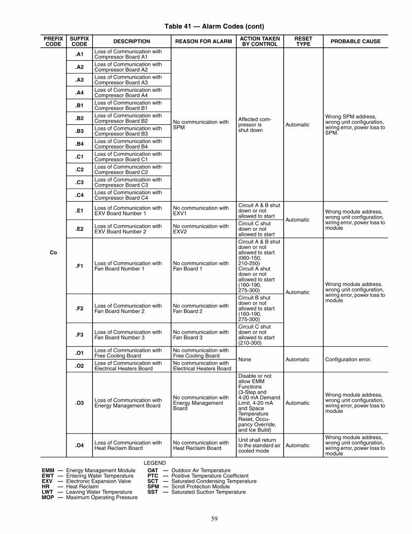
59
Table 41 — Alarm Codes (cont)
LEGEND
PREFIXCODE
SUFFIXCODE DESCRIPTION REASON FOR ALARM ACTION TAKEN
BY CONTROLRESETTYPE PROBABLE CAUSE
Co
.A1 Loss of Communication with Compressor Board A1
No communication with SPM
Affected com-pressor is shut down
Automatic
Wrong SPM address, wrong unit configuration, wiring error, power loss to SPM.
.A2 Loss of Communication with Compressor Board A2
.A3 Loss of Communication with Compressor Board A3
.A4 Loss of Communication with Compressor Board A4
.B1 Loss of Communication with Compressor Board B1
.B2 Loss of Communication with Compressor Board B2
.B3 Loss of Communication with Compressor Board B3
.B4 Loss of Communication with Compressor Board B4
.C1 Loss of Communication with Compressor Board C1
.C2 Loss of Communication with Compressor Board C2
.C3 Loss of Communication with Compressor Board C3
.C4 Loss of Communication with Compressor Board C4
.E1 Loss of Communication with EXV Board Number 1
No communication with EXV1
Circuit A & B shut down or not allowed to start
Automatic
Wrong module address, wrong unit configuration, wiring error, power loss to module.E2 Loss of Communication with
EXV Board Number 2No communication with EXV2
Circuit C shut down or not allowed to start
.F1 Loss of Communication with Fan Board Number 1
No communication with Fan Board 1
Circuit A & B shut down or not allowed to start (060-150, 210-250)Circuit A shut down or not allowed to start (160-190, 275-300) Automatic
Wrong module address, wrong unit configuration, wiring error, power loss to module
.F2 Loss of Communication with Fan Board Number 2
No communication with Fan Board 2
Circuit B shut down or not allowed to start (160-190, 275-300)
.F3 Loss of Communication with Fan Board Number 3
No communication with Fan Board 3
Circuit C shut down or not allowed to start (210-300)
.O1 Loss of Communication with Free Cooling Board
No communication with Free Cooling Board
None Automatic Configuration error..O2 Loss of Communication with
Electrical Heaters BoardNo communication with Electrical Heaters Board
.O3 Loss of Communication with Energy Management Board
No communication with Energy Management Board
Disable or not allow EMM Functions(3-Step and 4-20 mA Demand Limit, 4-20 mA and Space Temperature Reset, Occu-pancy Override, and Ice Build)
Automatic
Wrong module address, wrong unit configuration, wiring error, power loss to module
.O4 Loss of Communication with Heat Reclaim Board
No communication with Heat Reclaim Board
Unit shall return to the standard air cooled mode
Automatic
Wrong module address, wrong unit configuration, wiring error, power loss to module
EMM — Energy Management Module OAT — Outdoor Air TemperatureEWT — Entering Water Temperature PTC — Positive Temperature CoefficientEXV — Electronic Expansion Valve SCT — Saturated Condensing TemperatureHR — Heat Reclaim SPM — Scroll Protection ModuleLWT — Leaving Water Temperature SST — Saturated Suction TemperatureMOP — Maximum Operating Pressure

60
Table 41 — Alarm Codes (cont)
LEGEND
PREFIXCODE
SUFFIXCODE DESCRIPTION REASON FOR ALARM ACTION TAKEN
BY CONTROLRESETTYPE PROBABLE CAUSE
Ct
.01 Circuit A Welded Contactor Failure
Controls determine com-pressor is still running when circuit should be off
EXV, fan control, and pump oper-ate as normal to save compressor until high pres-sure, freeze, or flow failure condi-ions occur
ManualOne or more circuit com-pressor contactors welded closed.
.02 Circuit B Welded Contactor Failure
Controls determine com-pressor is still running when circuit should be off
EXV, fan control, and pump oper-ate as normal to save compressor until high pres-sure, freeze, or flow failure condi-ions occur
ManualOne or more circuit com-pressor contactors welded closed.
.03 Circuit C Welded Contactor Failure
Controls determine com-pressor is still running when circuit should be off
EXV, fan control, and pump oper-ate as normal to save compressor until high pres-sure, freeze, or flow failure condi-ions occur
ManualOne or more circuit com-pressor contactors welded closed.
FC.n0 Initial Factory Configuration
Required No configuration Unit not allowed to start Automatic
Configuration error. Pass-word may default to 0113.
.nn Illegal Configuration Wrong or incompatible configuration data
Unit not allowed to start Automatic Configuration error.
MC .nn Master Chiller Configuration Error
Wrong or incompatible configuration data
Unit not allowed to start in Master-Slave Control
Automatic Configuration error. Refer to Table 43.
P
.01 Water Exchanger Freeze Protection
Entering or Leaving Thermistor sensed a temperature at or below freeze point.
Unit shut down or not allowed to start. Chilled Water Pump will be started
Automatic, first occurrence in 24 hours, Manual, if multiple alarms within 24 hours
Faulty thermistor, faulty wiring, low water flow rate, low loop volume, or freeze conditions.
.05 Circuit A Low Suction Temperature
Low Saturated Suction Temperatures sensed for a period of time.
Circuit shut down
Automatic, first occurrence in 24 hours, Manual, if multiple alarms within 24 hours
Faulty transducer, faulty wiring, low water flow rate, low loop volume, fouled cooler, or freeze conditions.
.06 Circuit B Low Suction Temperature
.07 Circuit C Low Suction Temperature
.08 Circuit A High Superheat EXV>98%, Suction Superheat >54 F (30.0 C) and SST<MOP for more than 5 minutes
Circuit shut down Manual
Faulty transducer, faulty thermistor, faulty wiring, faulty EXV, low refriger-ant charge, plugged or restricted liquid line.
.09 Circuit B High Superheat
.10 Circuit C High Superheat
.11 Circuit A Low Superheat EXV 5% and Suction Superheat is less than the superheat setting by at least 5 F (2.8 C) or SST>Maximum Operat-ing Pressure for more than 5 minutes
Circuit shut down
Automatic, first occurrence in 24 hours, Manual, if multiple alarms within 24 hours
Faulty transducer, faulty thermistor, faulty wiring, faulty EXV, or incorrect configuration..12 Circuit B Low Superheat
.13 Circuit C Low Superheat
.14 Cooler Interlock Failure
Cooler Pump Interlock circuit opens (consists of chilled water flow system and chilled water pump interlock)
Unit shut down or not allowed to start
Automatic if stage=0, Manual if stage>0.
Low Water Flow, faulty wiring or contacts, faulty water flow switch, or chilled water pump problem. Remote lockout if unit is equipped with an EMM.
EMM — Energy Management Module OAT — Outdoor Air TemperatureEWT — Entering Water Temperature PTC — Positive Temperature CoefficientEXV — Electronic Expansion Valve SCT — Saturated Condensing TemperatureHR — Heat Reclaim SPM — Scroll Protection ModuleLWT — Leaving Water Temperature SST — Saturated Suction TemperatureMOP — Maximum Operating Pressure
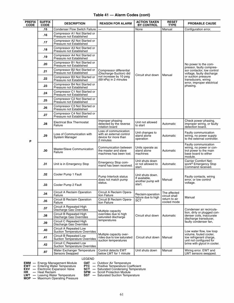
61
Table 41 — Alarm Codes (cont)
LEGEND
PREFIXCODE
SUFFIXCODE DESCRIPTION REASON FOR ALARM ACTION TAKEN
BY CONTROLRESETTYPE PROBABLE CAUSE
P
.15 Condenser Flow Switch Failure — None Manual Configuration error.
.16 Compressor A1 Not Started or Pressure not Established
Compressor differential (Discharge-Suction) did not increase by 10 psig (69 kPa) in 2 minutes
Circuit shut down Manual
No power to the com-pressor, faulty compres-sor contactor, low control voltage, faulty discharge or suction pressure transducers, wiring error, improper electrical phasing.
.17 Compressor A2 Not Started or Pressure not Established
.18 Compressor A3 Not Started or Pressure not Established
.19 Compressor A4 Not Started or Pressure not Established
.20 Compressor B1 Not Started or Pressure not Established
.21 Compressor B2 Not Started or Pressure not Established
.22 Compressor B3 Not Started or Pressure not Established
.23 Compressor B4 Not Started or Pressure not Established
.24 Compressor C1 Not Started or Pressure not Established
.25 Compressor C2 Not Started or Pressure not Established
.26 Compressor C3 Not Started or Pressure not Established
.27 Compressor C4 Not Started or Pressure not Established
.28 Electrical Box Thermostat Failure
Improper phasing detected by the reverse rotation board
Unit not allowed to start Automatic
Check power phasing, improper wiring, or faulty detection board.
.29 Loss of Communication with System Manager
Loss of communication with an external control device for more than 2 minutes
Unit changes to stand alone operation
AutomaticFaulty communication wiring, no power supply to the external controller.
.30 Master/Slave Communication Failure
Communication between the master and slave machines has been lost.
Units operate as stand alone machines
Automatic
Faulty communication wiring, no power or con-trol power to the main base board to either module.
.31 Unit is in Emergency Stop Emergency Stop com-mand has been received.
Unit shuts down or not allowed to start.
AutomaticCarrier Comfort Net-work® Emergency Stop Command received.
.32 Cooler Pump 1 FaultPump Interlock status does not match pump status.
Unit shuts down. If available, another pump will start.
ManualFaulty contacts, wiring error, or low control voltage.
.33 Cooler Pump 2 Fault
.34 Circuit A Reclaim Operation Failure
Circuit A Reclaim Opera-tion Failure Reclaim operation
failure due to high SCT
The affected circuit shall return to air cooled mode
Manual.35 Circuit B Reclaim Operation
FailureCircuit B Reclaim Opera-tion Failure
.37 Circuit A Repeated High Discharge Gas Overrides Multiple capacity
overrides due to high saturated discharge temperatures
Circuit shut down Automatic
Condenser air recircula-tion, dirty or plugged con-denser coils, inaccurate discharge transducer, faulty condenser fan,
.38 Circuit B Repeated High Discharge Gas Overrides
.39 Circuit C Repeated High Discharge Gas Overrides
.40 Circuit A Repeated Low Suction Temperature Overrides
Multiple capacity over-rides due to low saturated suction temperatures
Circuit shut down Manual
Low water flow, low loop volume, fouled cooler, low refrigerant charge, unit not configured for brine with glycol in cooler.
.41 Circuit B Repeated Low Suction Temperature Overrides
.42 Circuit C Repeated Low Suction Temperature Overrides
.97 Water Exchanger Temperature Sensors Swapped
Control detects EWT below LWT for 1 minute
Unit shuts down Manual Wiring error. EWT and LWT sensors swapped.
EMM — Energy Management Module OAT — Outdoor Air TemperatureEWT — Entering Water Temperature PTC — Positive Temperature CoefficientEXV — Electronic Expansion Valve SCT — Saturated Condensing TemperatureHR — Heat Reclaim SPM — Scroll Protection ModuleLWT — Leaving Water Temperature SST — Saturated Suction TemperatureMOP — Maximum Operating Pressure

62
Table 41 — Alarm Codes (cont)
LEGEND
PREFIXCODE
SUFFIXCODE DESCRIPTION REASON FOR ALARM ACTION TAKEN
BY CONTROLRESETTYPE PROBABLE CAUSE
Pr
.01 Circuit A Discharge Transducer
Measured voltage is 0 vdc
Circuit shut down or not allowed to start.
Automatic
Faulty transducer, wiring error, failed Main Base Board or Fan Board 3. Compressor circuit breaker tripped.
.02 Circuit B Discharge Transducer
.03 Circuit C Discharge Transducer
.04 Circuit A Suction Transducer
.05 Circuit B Suction Transducer
.06 Circuit C Suction Transducer
.07 Circuit A Reclaim Pumpdown Pressure Transducer The affected cir-
cuit shall return to air cooled mode
AutomaticFaulty transducer, wiringerror, failed EMM HR board..08 Circuit B Reclaim Pumpdown
Pressure Transducer
Sr .nn Service Maintenance AlertField programmed elapsed time has expired for maintenance item
None Manual Maintenance required (see Table 44).
th
.01 Water Exchanger Entering Fluid Thermistor Failure
Temperature measured by the controller is less than -40 F (-40 C) or greater than 240 F (115.6 C)
Unit will be shut down or not allowed to start.
AutomaticFaulty thermistor, wiring error, failed Main Base Board..02 Water Exchanger Leaving Fluid
Thermistor Failure
.03 Circuit A Defrost Thermistor Failure
None Automatic Configuration error..04 Circuit B Defrost Thermistor
Failure
.08 Reclaim Condenser Entering Thermistor
Unit shall return to the standard air cooled mode. Automatic
Faulty thermistor, wiringerror, failed EMM HR board.
.09 Reclaim Condenser Leaving Thermistor None
.10 OAT Thermistor Failure
Unit is shut down or not allowed to start. Cooler/Pump heaters are energized
AutomaticFaulty thermistor, wiring error, failed Main Base Board.
.11 Master/Slave Common Fluid Thermistor
Dual Chiller deac-tivated. Master and Slave machines oper-ate in stand alone mode
.12 Circuit A Suction Gas Thermistor
Temperature measured by the controller is less than -40 F (-40 C) or greater than 240 F (115.6 C)
Circuit shut down
AutomaticFaulty thermistor, wiring error, failed Main Base Board or EXV Board
.13 Circuit B Suction Gas Thermistor Circuit shut down
.14 Circuit C Suction Gas Thermistor Circuit shut down
.18 Circuit A Condenser Subcool-ing Liquid Thermistor Unit shall return
to the standard air cooled mode.
Automatic
Faulty thermistor, wiringerror, failed EMM HR board..19 Circuit B Condenser Subcool-
ing Liquid Thermistor
.21 Space Temperature Sensor Failure
Temperature Reset based on Space Tempera-ture disabled
Faulty thermistor, wiring error, failed Main Base Board.
EMM — Energy Management Module OAT — Outdoor Air TemperatureEWT — Entering Water Temperature PTC — Positive Temperature CoefficientEXV — Electronic Expansion Valve SCT — Saturated Condensing TemperatureHR — Heat Reclaim SPM — Scroll Protection ModuleLWT — Leaving Water Temperature SST — Saturated Suction TemperatureMOP — Maximum Operating Pressure
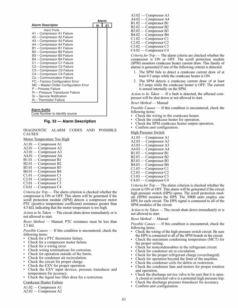
63
DIAGNOSTIC ALARM CODES AND POSSIBLECAUSESMotor Temperature Too HighA1.01 — Compressor A1A2.01 — Compressor A2A3.01 — Compressor A3A4.01 — Compressor A4B1.01 — Compressor B1B2.01 — Compressor B2B3.01 — Compressor B3B4.01 — Compressor B4C1.01 — Compressor C1C2.01 — Compressor C2C3.01 — Compressor C3C4.01 — Compressor C4Criteria for Trip — The alarm criterion is checked whether thecompressor is ON or OFF. This alarm will be generated if thescroll protection module (SPM) detects a compressor motorPTC (positive temperature coefficient) resistance greater than4.5 k, indicating that the motor temperature is too high.Action to be Taken — The circuit shuts down immediately or isnot allowed to start.Reset Method — Manual. PTC resistance must be less than2.5 kPossible Causes — If this condition is encountered, check thefollowing items:• Check for a PTC thermistor failure.• Check for a compressor motor failure.• Check for a wiring error.• Check wiring terminations for corrosion.• Check for operation outside of the limits.• Check for condenser air recirculation.• Check the circuit for proper charge.• Check the EXV for proper operation.• Check the EXV input devices, pressure transducer and
temperature for accuracy.• Check the liquid line filter drier for a restriction.Crankcase Heater FailureA1.02 — Compressor A1A2.02 — Compressor A2
A3.02 — Compressor A3A4.02 — Compressor A4B1.02 — Compressor B1B2.02 — Compressor B2B3.02 — Compressor B3B4.02 — Compressor B4C1.02 — Compressor C1C2.02 — Compressor C2C3.02 — Compressor C3C4.02 — Compressor C4Criteria for Trip — The alarm criteria are checked whether thecompressor is ON or OFF. The scroll protection module(SPM) monitors crankcase heater current draw. This family ofalarms is generated if one of the following criteria is detected:
1. The SPM fails to detect a crankcase current draw of atleast 0.5 amps while the crankcase heater is ON.
2. The SPM detects a crankcase current draw of at least0.5 amps while the crankcase heater is OFF. The currentis sensed internally on the SPM.
Action to be Taken — If a fault is detected, the affected com-pressor will be shut down or not allowed to start.Reset Method — ManualPossible Causes — If this condition is encountered, check thefollowing items:• Check the wiring to the crankcase heater.• Check the crankcase heater for operation.• Check the SPM crankcase heater output operation.• Confirm unit configuration.High Pressure SwitchA1.03 — Compressor A1A2.03 — Compressor A2A3.03 — Compressor A3A4.03 — Compressor A4B1.03 — Compressor B1B2.03 — Compressor B2B3.03 — Compressor B3B4.03 — Compressor B4C1.03 — Compressor C1C2.03 — Compressor C2C3.03 — Compressor C3C4.03 — Compressor C4Criteria for Trip — The alarm criterion is checked whether thecircuit is ON or OFF. This alarm will be generated if the circuithigh pressure switch (HPS) opens. The scroll protection mod-ule (SPM) monitors the HPS. The 30RB units employ oneHPS for each circuit. The HPS signal is connected to all of theSPM modules of the circuit.Action to be Taken — The circuit shuts down immediately or isnot allowed to start.Reset Method — ManualPossible Causes — If this condition is encountered, check thefollowing items:• Check the wiring of the high pressure switch circuit. Be sure
the HPS is connected to all of the SPM boards in the circuit.• Check the maximum condensing temperature (MCT) for
the proper setting.• Check for noncondensables in the refrigerant circuit.• Check for condenser air re-circulation.• Check for the proper refrigerant charge (overcharged).• Check for operation beyond the limit of the machine.• Check the condenser coils for debris or restriction.• Check the condenser fans and motors for proper rotation
and operation.• Check the discharge service valve to be sure that it is open.
A closed or restricted valve is a potential high pressure trip.• Check the discharge pressure transducer for accuracy.• Confirm unit configuration.
Alarm Descriptor th
Alarm SuffixCode Number to identify source
.01Alarm Prefix
A1 – Compressor A1 FailureA2 – Compressor A2 FailureA3 – Compressor A3 FailureA4 – Compressor A4 FailureB1 – Compressor B1 FailureB2 – Compressor B2 FailureB3 – Compressor B3 FailureB4 – Compressor B4 FailureC1 – Compressor C1 FailureC2 – Compressor C2 FailureC3 – Compressor C3 FailureC4 – Compressor C4 FailureCo – Communication FailureFC – Factory Configuration ErrorMC – Master Chiller Configuration ErrorP – Process FailurePr – Pressure Transducer FailureSr – Service Notificationth – Thermistor Failure
Alarm
Fig. 33 — Alarm Description

64
Motor Sensor PTC Out of RangeA1.04 — Compressor A1 A2.04 — Compressor A2 A3.04 — Compressor A3 A4.04 — Compressor A4 B1.04 — Compressor B1 B2.04 — Compressor B2 B3.04 — Compressor B3 B4.04 — Compressor B4 C1.04 — Compressor C1 C2.04 — Compressor C2 C3.04 — Compressor C3 C4.04 — Compressor C4 Criteria for Trip — The alarm criterion is checked whether thecircuit is ON or OFF. The scroll protection module (SPM)monitors the compressor motor temperature. This alarm willbe generated if the motor sensor PTC in the compressor resis-tance is less than 50 or greater than 17 k.Action to be Taken — The circuit shuts down immediately ornot allowed to start.Reset Method — ManualPossible Causes — If this condition is encountered, check thefollowing items:• Check the sensor wiring to the scroll compressor protec-
tion module (SPM).• Check for a faulty SPM.• Check for a compressor failure.• Check for noncondensables in the refrigerant circuit.• Check for condenser air re-circulation.• Check for the proper refrigerant charge (overcharged).• Check for operation beyond the limit of the machine.• Check the condenser coils for debris or restriction.• Check the condenser fans and motors for proper rotation
and operation.• Check the discharge service valve to be sure that it is open.• Check the discharge pressure transducer for accuracy.• Confirm unit configuration.SPM Board Power ResetA1.05 – Compressor A1A2.05 – Compressor A2A3.05 – Compressor A3A4.05 – Compressor A4B1.05 – Compressor B1B2.05 – Compressor B2B3.05 – Compressor B3B4.05 – Compressor B4C1.05 – Compressor C1C2.05 – Compressor C2C3.05 – Compressor C3C4.05 – Compressor C4Criteria for Trip — The alarm criterion is checked whether thecompressor is ON or OFF. The scroll protection module(SPM) monitors the 24 vac at the compressor through the highpressure switch input channel. This alarm will be generated ifthe main base board receives a signal from the SPM boardindicating that the compressor went through a power cycle.Action to be Taken — The compressor is shut down immedi-ately or not allowed to start.Reset Method — AutomaticPossible Causes — If this condition is encountered, check thefollowing items:• Check the voltage from the main three phase power
supply• Check the 24 vac wiring connections to the scroll com-
pressor protection module (SPM)• Check for a faulty SPM.SPM Board Low Control Voltage AlertA1.06 – Compressor A1
A2.06 – Compressor A2A3.06 – Compressor A3A4.06 – Compressor A4B1.06 – Compressor B1B2.06 – Compressor B2B3.06 – Compressor B3B4.06 – Compressor B4C1.06 – Compressor C1C2.06 – Compressor C2C3.06 – Compressor C3C4.06 – Compressor C4Criteria for Trip — The alarm criterion is checked whether thecompressor is ON or OFF. The scroll protection module(SPM) monitors the 24 vac at the compressor through the highpressure switch input channel. This alarm will be generated ifthe main base board receives a signal from the SPM boardindicating that the 24 vac level was lower than the allowedminimum threshold.Action to be Taken — The compressor is shut down immedi-ately or not allowed to start as to prevent any contactor chatter-ing/welding from occurring.Reset Method — AutomaticPossible Causes — If this condition is encountered, check thefollowing items:• Check the voltage from the main three phase power
supply.• Check the 24 vac wiring connections to the scroll com-
pressor protection module (SPM).• Check for a faulty SPM.Loss of Communication with CompressorCo.A1 — Board A1Co.A2 — Board A2Co.A3 — Board A3Co.A4 — Board A4Co.B1 — Board B1Co.B2 — Board B2Co.B3 — Board B3Co.B4 — Board B4Co.C1 — Board C1Co.C2 — Board C2Co.C3 — Board C3Co.C4 — Board C4Criteria for Trip — The alarm criterion is tested whether theunit is ON or OFF. If communication with the scroll compres-sor protection module (SPM) is lost for a period of 10 seconds,the alarm will be generated.Action to be Taken — The affected compressor will be shutdown.Reset Method — Automatic, if communication is established,the compressor, if called for will start normally.Possible Causes — If this condition is encountered, check thefollowing items:• Check the power supply to the affected SPM.• Check the address of the SPM to be sure that it is correct.• Check the Local Equipment Network (LEN) wiring to be
sure that it is connected properly.• Confirm unit configuration.Co.E1— Loss of Communication with EXV Board Number 1Criteria for Trip — The alarm criterion is tested whether theunit is ON or OFF. If communication with EXV1 is lost for aperiod of 10 seconds, the alarm will be triggered.Action to be Taken — If running, Circuit A and B will shutdown normally. If Circuit A or Circuit B is not operating, itwill not be allowed to start.Reset Method — Automatic, if communication is established,the unit will start normally.

65
Possible Causes — If this condition is encountered, check thefollowing items:• Check the power supply to EXV1.• Check the address of the EXV1 to be sure that it is
correct.• Check the Local Equipment Network (LEN) wiring to be
sure that it is connected properly.• Confirm unit configuration.Co.E2 — Loss of Communication with EXV Board Number 2Criteria for Trip — The alarm criterion is tested whether theunit is ON or OFF, on 30RB210-300 units only.Action to be Taken — If communication with EXV Board 2 islost for a period of 10 seconds, the alarm will be triggered. Ifrunning, Circuit C will shut down normally. If Circuit C is notrunning, it will not be allowed to start.Reset Method — Automatic, if communication is established,the unit will start normally.Possible Causes — If this condition is encountered, check thefollowing items:• Check the power supply to EXV Board 2.• Check the address of the EXV Board 2 to be sure that it
is correct.• Check the Local Equipment Network (LEN) wiring to be
sure that it is connected properly.• Confirm unit configuration.Co.F1 — Loss of Communication with Fan Board Number 1Criteria for Trip — The criterion is tested whether the unit isON or OFF. If communication with Fan Board 1 is lost for aperiod of 10 seconds, the alarm will be triggered.Action to be Taken — For 30RB060-150 and 30RB210-250,Circuit A and B will shut down normally if they are running.For 30RB160-190 and 30RB275-300, Circuit A will shutdown normally if it is running. If the circuit or circuits con-trolled by the board are not running, then they will not beallowed to start.Reset Method — Automatic, if communication is established,the unit will start normally.Possible Causes — If this condition is encountered, check thefollowing items:• Check the power supply to Fan Board 1.• Check the address of the Fan Board 1 to be sure that it is
correct.• Check the Local Equipment Network (LEN) wiring to be
sure that it is connected properly.• Confirm unit configuration.Co.F2 — Loss of Communication with Fan Board Number 2Criteria for Trip — The criterion is tested whether the unit isON or OFF and on 30RB160-190, 275, and 300 only. Action to be Taken — If communication with Fan Board 2 islost for a period of 10 seconds, the alarm will be triggered. Ifrunning, Circuit B will shut down normally for 30RB160-190,275 and 300. If Circuit B is not running for 30RB160-190, 275and 300, then it will not be allowed to start.Reset Method — Automatic, if communication is established,the unit will start normally.Possible Causes — If this condition is encountered, check thefollowing items:• Check the power supply to Fan Board 2.• Check the address of the Fan Board 2 to be sure that it is
correct.• Check the Local Equipment Network (LEN) wiring to be
sure that it is connected properly.• Confirm unit configuration.Co.F3 — Loss of Communication with Fan Board Number 3Criteria for Trip — The criterion is tested whether the unit isON or OFF, and on 30RB210-300 machines only. If
communication with Fan Board 3 is lost for a period of 10 sec-onds, the alarm will be triggered.Action to be Taken — If running, Circuit C will shut down nor-mally for 30RB210-300. If the circuit is not running for30RB210-300, then it will not be allowed to start.Reset Method — Automatic, if communication is established,the unit will start normally.Possible Causes — If this condition is encountered, check thefollowing items:• Check the power supply to Fan Board 3.• Check the address of the Fan Board 3 to be sure that it is
correct.• Check the Local Equipment Network (LEN) wiring to be
sure that it is connected properly.• Confirm unit configuration.Co.O1 — Loss of Communication with Free Cooling BoardCriteria for Trip — This alarm is for a free cooling machineonly. This feature is not supported for a cooling only machine.Action to be Taken — NoneReset Method — AutomaticPossible Causes — If this condition is encountered, confirmunit configuration.Co.O2 — Loss of Communication with Electrical Heaters BoardCriteria for Trip — This alarm is for a heat pump machinesonly. This feature is not supported for a cooling only machine.Action to be Taken — NoneReset Method — AutomaticPossible Causes — If this condition is encountered, confirmunit configuration.Co.O3 — Loss of Communication with Energy Management BoardCriteria for Trip — The criterion is tested whether the unit isON or OFF and when a function that requires the energymanagement module (EMM) is configured. If communicationwith the EMM is lost for a period of 10 seconds, the alarm willbe triggered.Action to be Taken — If any function controlled by the EMM(3-Step and 4-20 mA Demand Limit, 4-20 mA and SpaceTemperature Reset, Occupancy Override, and Ice Build) isactive, that function will be terminated. If an EMM function isprogrammed, and communication is lost, the function will notbe allowed to start.Reset Method — Automatic, if communication is established,the functions will be enabled.Possible Causes — If this condition is encountered, check thefollowing items:• Check configuration to see if the EMM is installed, (Con-
figurationUNITEMM). If (EMM=YES), check fora control option that requires the EMM that may beenabled. Correct configuration if not correct.
• Check the power supply to EMM.• Check the address of the EMM to be sure that it is correct.• Check the Local Equipment Network (LEN) wiring to be
sure that it is connected properly.• Check unit configuration to be sure that no options that
require the EMM are enabled.Co.O4 — Loss of Communication with Heat Reclaim BoardCriteria for Trip — This alarm is tested whether the unit isON or OFF and when the unit is configured for Heat Reclaim.If communication with the heat reclaim board is lost for aperiod of 10 seconds, the alarm will be triggered.Action to be Taken — The unit will return to the air cooledmode.Reset Method — Automatic, when communication is estab-lished, the functions will be enabled.

66
Possible Causes — If this condition is encountered, check thefollowing items:• Check the power supply to heat reclaim board.• Check the Local Equipment Network (LEN) wiring to be
sure that it is connected properly.• Check unit configuration to be sure that Heat Reclaim is
enabled and unit does NOT contain the Heat Reclaimoption.
Welded Contactor FailureCt.01 – Circuit ACt.02 – Circuit BCt.03 – Circuit CCriteria For Trip — This alarm is tested for when the circuit isoff (all compressors switched to off). The algorithm will evalu-ate saturated suction and saturated condensing temperatures todetermine if the compressor is still running even though it hasbeen commanded off.Action to be Taken
1. Unit capacity will go to and remain at 0%. The EXV, fancontrol, and cooler pump will continue their normal oper-ation.
2. If a high pressure, cooler flow, or cooler freeze failure oc-curs, then circuit operation is disabled. The critical alarmrelay will be energized in order to shut off the main powersupply.
Reset Method — Reset is manual.FC.n0 — Initial Factory Configuration RequiredCriteria for Trip — The criterion is tested whether the unit isON or OFF. The alarm will be generated if the ConfigurationUNITTONS=0.Action to be Taken — The unit is not allowed to start.Reset Method — Automatic after factory configuration is com-plete. The configuration must be manually completed. Thepassword may default to 0113.Possible Causes — If this condition is encountered, confirmthe unit configuration.FC.nn — Illegal ConfigurationCriteria for Trip — The criterion is tested whether the unit isON or OFF. The alarm will be generated if the one of the fol-lowing configuration errors is detected by the control. The“nn” refers to the error code listed in Table 42.
Table 42 — Illegal Configuration Alarm Code
Action to be Taken — The unit is not allowed to start.Reset Method — Automatic after factory reconfiguration iscompleted. A power cycle may be required.Possible Causes — If this condition is encountered, confirmthe unit configuration.MC.nn — Master Chiller Configuration ErrorCriteria for Trip — The criterion is tested whether the unit isON or OFF. The units must be configured as a Master and
Slave machine (ConfigurationRSETMSSL=1 and Con-figurationRSETMSSL=2), and one of the followingconfiguration errors has been found. The “nn” refers to theerror code listed in Table 43.Action to be Taken — Unit not allowed to start in Master Slavecontrol.Reset Method — AutomaticPossible Causes — If this condition is encountered, confirmproper configuration.P.01 — Water Exchanger Freeze ProtectionCriteria for Trip — The alarm criteria are checked whether theunit is ON or OFF. If the entering or leaving water thermistorsenses a temperature at the freeze point or less, the alarm willbe generated. For a fresh water system (ConfigurationSERVFLUD=1), the freeze point is 34 F (1.1 C).For medium temperature brine systems (ConfigurationSERVFLUD=2), the freeze point is Brine Freeze SetPoint (ConfigurationSERVLOSP).Action to be Taken — Unit shut down or not allowed to start.Chilled water pump will be started.Reset Method — Automatic, first occurrence in 24 hours ifLWT rises to 6° F (3° C) above set point. Manual, if more thanone occurrence in 24 hours.Possible Causes — If this condition is encountered, check thefollowing items:• Check the entering and leaving fluid thermistors for
accuracy.• Check the water flow rate.• Check loop volume. Low loop volume at nominal flow
rates can in extreme cases bypass cold water to thecooler.
• Check for freezing conditions.• Check heater tape and other freeze protection items for
proper operation.• Check glycol concentration and adjust LOSP accord-
ingly.• If the Leaving Water Set Point is above 40 F (4.4 C) and
there is glycol in the loop, consider using the MediumTemperature Brine option (ConfigurationSERVFLUD=2) to utilize the brine freeze pointinstead of 34 F (1.1 C).
Low Suction TemperatureP.05 — Circuit A P.06 — Circuit B P.07 — Circuit C Criteria for Trip — The criteria are tested whether the circuit isON. This alarm is generated if one of the following criteria ismet:• If the circuit Saturated Suction Temperature is below
–13 F (–25 C) for more than 30 seconds.• If the circuit Saturated Suction Temperature is below
–22 F (–30 C) for more than 8 seconds.• If the circuit Saturated Suction Temperature is below
–40 F (–40 C) for more than 3 seconds.Action to be Taken — The circuit is shut down immediately.
Prior to the alarm trip, the control will take action to avoidthe alarm. See Operating Modes 21, 22 and 23 on page 48.• Reset Method — Automatic, first occurrence in 24 hours.
Manual, if more than one occurrence in 24 hours.
FC ERROR CODE
DESCRIPTION
01 Unit size is unknown.02 Reclaim option selected for Heat Pump machine.
03 Hot Gas Bypass configured for a Heat Pump machine.
04 Number of Fans controlled by Motormaster® con-trol is greater than expected.

67
Table 43 — Master/Slave Alarm Code
LEGEND
Possible Causes — If this condition is encountered, check thefollowing items:• Check the sensor wiring to Main Base Board (P.05 and
P.06) or Fan Board 3 (P.07).• Check the board for a faulty channel.• Check for a faulty transducer.• Check cooler water flow.• Check loop volume.• Check EXV operation.• Check for a liquid line refrigerant restriction, filter drier,
service valve, etc.• Check the refrigerant charge.• If the Leaving Water Set Point is above 40 F (4.4 C)
and there is glycol in the loop, consider using theMedium Temperature Brine option (ConfigurationSERVFLUD=2) to utilize the brine freeze pointinstead of 34 F (1.1 C).
High SuperheatP.08 — Circuit A P.09 — Circuit B P.10 — Circuit C Criteria for Trip — The criteria are tested whether the circuit isON. This alarm is generated if all of the following criteria aremet:
1. The EXV position is equal to or greater than 98%.2. The circuit’s Suction Superheat (Suction Gas Tempera-
ture – Saturated Suction Temperature) is greater than 54 F(30.0 C).
3. The circuit’s Saturated Suction Temperature is less thanMaximum Operating Pressure (MOP) set point (Config-urationSERVMOP) for more than 5 minutes.
Action to be Taken — The circuit is shut down normally.Reset Method — Manual.Possible Causes — If this condition is encountered, check thefollowing items:• Check the suction pressure transducer wiring to Main
Base Board (P.08 and P.09) or Fan Board 3 (P.10).• Check the board for a faulty channel.• Check for a faulty transducer.• Check the suction gas thermistor wiring to EXV Board 1
(P.08 and P.09) or to EXV Board 2 (P.10)• Check the suction gas thermistor sensor for accuracy.
• Check for EXV Board 1 (P.08 and P.09) or EXV Board 2(P.10) faulty channel.
• Check EXV operation.• Check for a liquid line refrigerant restriction, filter drier,
service valve, etc.• Check the refrigerant charge.Low SuperheatP.11 — Circuit A P.12 — Circuit B P.13 — Circuit C Criteria for Trip — The criteria are tested whether the circuit isON. This alarm is generated if the following criterion is met:
The EXV position is equal to or less than 5% and the cir-cuit’s Suction Superheat (Suction Gas Temperature – SaturatedSuction Temperature) is less than the Suction Superheat SetPoint (ConfigurationSERVSHP.A, ConfigurationSERVSHP.B, or ConfigurationSERVSHP.C) by atleast 5° F (2.8° C) or the circuit Saturated Suction Temperatureis greater than Maximum Operating Pressure (MOP) set point(ConfigurationSERVMOP) for more than 5 minutes.Action to be Taken — The circuit is shut down normally.Reset Method — Automatic, first occurrence in 24 hours.Manual, if more than one occurrence in 24 hours.Possible Causes — If this condition is encountered, check thefollowing items:• Check the suction pressure transducer wiring to Main
Base Board (P.11 and P.12) or Fan Board 3 (P.13).• Check the board for a faulty channel.• Check for a faulty transducer.• Check the suction gas thermistor wiring to EXV Board 1
(P.08 and P.09) or to EXV Board 2 (P.10)• Check the suction gas thermistor sensor for accuracy.• Check for EXV Board 1 (P.11 and P.12) or EXV Board 2
(P.13) faulty channel. • Check EXV operation.• Confirm Maximum Operating Pressure Set Point.• Check the refrigerant charge.P.14 — Cooler Interlock FailureCriteria for Trip — The criteria are tested whether the unit isON or OFF. This algorithm monitors the cooler flow switchcircuit, which may include field-installed cooler pumpinterlock (PMPI) contacts. The pump interlock and flowswitch are wired in series, therefore either device can cause a
MC ERROR CODE
MASTER SLAVE DESCRIPTION
01 X X The master or slave water pump is not configured while the control of the lag unit pump is required (lag_pump = 1)
02 X Master and slave units have the same network address.03 X There is no slave configured at the slave address04 X Slave pump_seq incorrect configuration
05 X There is a conflict between the master and the slave LWT option: the master is configured for EWT control while the slave is configured for LWT control.
06 X There is a conflict between the master and the slave LWT option: the master is configured for LWT control while the slave is configured for EWT control.
07 X There is a conflict between the master and the slave pump option: the master is configured for lag pump control while the slave is not configured for lag pump control.
08 X There is a conflict between the master and the slave pump option: the master is not configured for lag pump control while the slave is configured for lag pump control.
09 X X The slave chiller is in local or remote control (chilstat = 3)10 X X The slave chiller is down due to fault (chilstat = 5)11 X The master chiller operating type is not Master: master_oper_typ and master_status = off12 X X No communication with slave.13 X Master and slave heat/cool status are not the same.
EWT — Entering Water TemperatureLWT — Leaving Water Temperature
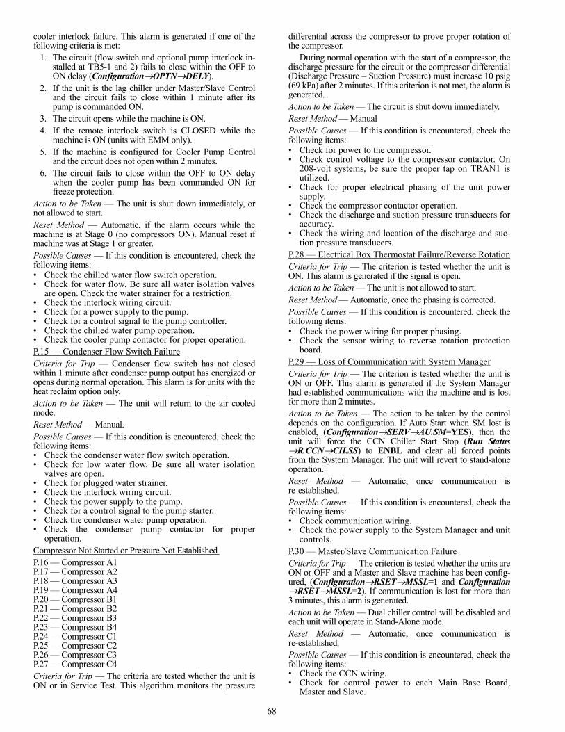
68
cooler interlock failure. This alarm is generated if one of thefollowing criteria is met:
1. The circuit (flow switch and optional pump interlock in-stalled at TB5-1 and 2) fails to close within the OFF toON delay (ConfigurationOPTNDELY).
2. If the unit is the lag chiller under Master/Slave Controland the circuit fails to close within 1 minute after itspump is commanded ON.
3. The circuit opens while the machine is ON.4. If the remote interlock switch is CLOSED while the
machine is ON (units with EMM only).5. If the machine is configured for Cooler Pump Control
and the circuit does not open within 2 minutes.6. The circuit fails to close within the OFF to ON delay
when the cooler pump has been commanded ON forfreeze protection.
Action to be Taken — The unit is shut down immediately, ornot allowed to start.Reset Method — Automatic, if the alarm occurs while themachine is at Stage 0 (no compressors ON). Manual reset ifmachine was at Stage 1 or greater.Possible Causes — If this condition is encountered, check thefollowing items:• Check the chilled water flow switch operation.• Check for water flow. Be sure all water isolation valves
are open. Check the water strainer for a restriction.• Check the interlock wiring circuit.• Check for a power supply to the pump.• Check for a control signal to the pump controller.• Check the chilled water pump operation.• Check the cooler pump contactor for proper operation.P.15 — Condenser Flow Switch FailureCriteria for Trip — Condenser flow switch has not closedwithin 1 minute after condenser pump output has energized oropens during normal operation. This alarm is for units with theheat reclaim option only.Action to be Taken — The unit will return to the air cooledmode.Reset Method — Manual.Possible Causes — If this condition is encountered, check thefollowing items:• Check the condenser water flow switch operation.• Check for low water flow. Be sure all water isolation
valves are open.• Check for plugged water strainer.• Check the interlock wiring circuit.• Check the power supply to the pump.• Check for a control signal to the pump starter.• Check the condenser water pump operation.• Check the condenser pump contactor for proper
operation.Compressor Not Started or Pressure Not Established P.16 — Compressor A1 P.17 — Compressor A2 P.18 — Compressor A3 P.19 — Compressor A4 P.20 — Compressor B1 P.21 — Compressor B2 P.22 — Compressor B3 P.23 — Compressor B4 P.24 — Compressor C1 P.25 — Compressor C2 P.26 — Compressor C3 P.27 — Compressor C4 Criteria for Trip — The criteria are tested whether the unit isON or in Service Test. This algorithm monitors the pressure
differential across the compressor to prove proper rotation ofthe compressor.
During normal operation with the start of a compressor, thedischarge pressure for the circuit or the compressor differential(Discharge Pressure – Suction Pressure) must increase 10 psig(69 kPa) after 2 minutes. If this criterion is not met, the alarm isgenerated.Action to be Taken — The circuit is shut down immediately.Reset Method — ManualPossible Causes — If this condition is encountered, check thefollowing items:• Check for power to the compressor.• Check control voltage to the compressor contactor. On
208-volt systems, be sure the proper tap on TRAN1 isutilized.
• Check for proper electrical phasing of the unit powersupply.
• Check the compressor contactor operation.• Check the discharge and suction pressure transducers for
accuracy.• Check the wiring and location of the discharge and suc-
tion pressure transducers.P.28 — Electrical Box Thermostat Failure/Reverse RotationCriteria for Trip — The criterion is tested whether the unit isON. This alarm is generated if the signal is open.Action to be Taken — The unit is not allowed to start.Reset Method — Automatic, once the phasing is corrected.Possible Causes — If this condition is encountered, check thefollowing items:• Check the power wiring for proper phasing.• Check the sensor wiring to reverse rotation protection
board.P.29 — Loss of Communication with System ManagerCriteria for Trip — The criterion is tested whether the unit isON or OFF. This alarm is generated if the System Managerhad established communications with the machine and is lostfor more than 2 minutes.Action to be Taken — The action to be taken by the controldepends on the configuration. If Auto Start when SM lost isenabled, (ConfigurationSERVAU.SM=YES), then theunit will force the CCN Chiller Start Stop (Run StatusR.CCNCH.SS) to ENBL and clear all forced pointsfrom the System Manager. The unit will revert to stand-aloneoperation.Reset Method — Automatic, once communication isre-established.Possible Causes — If this condition is encountered, check thefollowing items:• Check communication wiring.• Check the power supply to the System Manager and unit
controls.P.30 — Master/Slave Communication FailureCriteria for Trip — The criterion is tested whether the units areON or OFF and a Master and Slave machine has been config-ured, (ConfigurationRSETMSSL=1 and ConfigurationRSETMSSL=2). If communication is lost for more than3 minutes, this alarm is generated.Action to be Taken — Dual chiller control will be disabled andeach unit will operate in Stand-Alone mode.Reset Method — Automatic, once communication isre-established.Possible Causes — If this condition is encountered, check thefollowing items:• Check the CCN wiring.• Check for control power to each Main Base Board,
Master and Slave.

69
• Confirm correct configuration.P.31 — Unit is in Emergency StopCriteria for Trip — The criterion is tested whether the units areON or OFF and the machine receives a Carrier Comfort Net-work® (CCN) command for an Emergency Stop.Action to be Taken — Unit will stop, or not allowed to start.Reset Method — Automatic, once a return to normal commandis received.Possible Causes — If this condition is encountered, check forCCN Emergency Stop command.Cooler Pump FaultP.32 — Pump 1 FaultP.33 — Pump 2 FaultCriteria for Trip — The criterion is tested whether the units areON or OFF. This alarm will be generated if the cooler pumpinterlock opens. When starting the pump, the control must readan open circuit for 3 consecutive reads. If the pump is operat-ing and the circuit opens, the alarm will be generated immedi-ately.Action to be Taken — The pump and machine will be shutdown. If there is another pump available, the control will startthat pump, restart the machine and clear the alarm. If no otherpump is available, the unit will remain OFF. Reset Method — Manual.Possible Causes — If this condition is encountered, check thefollowing items:• Check the interlock wiring circuit.• Check for a control signal to the pump controller.• Check the cooler pump contactor for proper operation.• Check control voltage for proper voltage. On 208-volt
systems, be sure the proper tap on TRAN1 is utilized.Reclaim Operation FailureP.34 — Circuit A P.35 — Circuit B Criteria for Trip — Reclaim operation failure due to high SCT.This alarm is for units with the heat reclaim option only.Action to be Taken — The affected circuit will return to aircooled mode.Reset Method — Manual.Possible Causes — If this condition is encountered, check thefollowing items:• Check for low water flow. Be sure all water isolation
valves are open.• Check for plugged water strainer.• Check for fouled tubes in reclaim condenser.Repeated High Discharge Gas OverridesP.37 — Circuit A P.38 — Circuit B P.39 — Circuit C Criteria for Trip — The criterion is tested when the circuit isON. This alarm will be tripped if the circuit capacity is reducedmore than 8 times in 30 minutes due to high discharge gas tem-peratures. If no override occurs in a 30-minute period, thecounter is reset.Action to be Taken — The affected circuit will be shut down.Reset Method — Automatic, after 30 minutes. If the alarm iscleared via the Manual method, the counter will be reset tozero.Possible Causes — If this condition is encountered, check thefollowing items:• Check the maximum condensing temperature (MCT) for
the proper setting.• Check for noncondensables in the refrigerant circuit.• Check for condenser air re-circulation.
• Check for the proper refrigerant charge (overcharged).• Check for operation beyond the limit of the machine.• Check the condenser coils for debris or restriction.• Check the condenser fans and motors for proper rotation
and operation.• Check the discharge service valve to be sure that it
is open. Check the discharge pressure transducer foraccuracy.
• Confirm unit configuration.Repeated Low Suction Temperature OverridesP.40 – Circuit AP.41 – Circuit BP.42 – Circuit CCriteria for Trip — This alarm was added in software version1.09. The criterion is active when circuit is ON. If the circuit’scapacity is reduced more than 6 times by the Capacity Over-ride 23 (Circuit A), 24 (Circuit B), or 25 (Circuit C) for therespective circuit, without at least 30 minutes elapsing betweenthe capacity reductions, the alarm is triggered. If at least30 minutes elapses without a reduction in capacity, the counteris reset to zero.Action to be Taken — Circuit shut down.Reset Method — Manual.Possible Causes — If this condition is encountered, check thefollowing items:• Confirm unit configuration.• Check EXV operation.• Check for a liquid line refrigerant restriction, service valve
partially closed, filter drier with excessive pressure drop.• Check the refrigerant charge.• Check suction pressure transducer accuracy.• Check return gas thermistor accuracy.• Check Circuit Superheat Set Point (Configuration
SERVSHP.A, SHP.B, or SHP.C).• Check if system contains antifreeze (Configuration
SERVFLUD=2).• Check Brine Freeze Set Point (Configuration
SERVLOSP) if an antifreeze solution is used.• Check fluid flow rate.• Check strainer for a restriction, clean if necessary.• Check for cooler fouling.• Check compressor oil level. If oil level is above the top
of the sightglass, then oil may be logging in the cooler.Adjust oil level in compressor(s).
P.97 — Water Exchanger Temperature Sensors SwappedCriteria for Trip — The alarm criterion is checked when thechiller is ON and one or more compressors is running. Thisalarm will be tripped if the entering water temperature is lessthan the leaving water temperature for more than 1 minute.Action to be Taken — The chiller is shut down immediately.Reset Method — ManualPossible Causes — If this condition is encountered, check thefollowing items:• Check LWT and EWT wiring at main base board (con-
nector J6, channels 1,2) .• Check for a faulty entering or leaving water temperature
sensor.• Check cooler nozzles for proper water temperature sen-
sor locations.Discharge Transducer FailurePr.01 — Circuit A Pr.02 — Circuit B Pr.03 — Circuit C Criteria for Trip — The criterion is tested whether the circuit isON or OFF. This alarm is generated if the voltage as sensed bythe MBB or FB3 is 0 vdc.

70
Action to be Taken — The circuit is shut down normally, or notallowed to start.Reset Method — Automatic, once the transducer voltage isgreater than 0 vdc.Possible Causes — If this condition is encountered, check thefollowing items:• Check the sensor wiring to main base board (Pr.01 and
Pr.02).• Check the sensor wiring to Fan Board 3 (Pr.03).• Check the board for a faulty channel.• Check for a faulty transducer.• Confirm unit configuration.Suction Transducer FailurePr.04 — Circuit A Pr.05 — Circuit B Pr.06 — Circuit C Criteria for Trip — The criteria are tested whether the circuit isON or OFF. The alarm is generated if one of the following cri-teria is met:
1. This alarm is generated if the voltage as sensed by theMBB or FB3 is 0 vdc.
2. The circuit is ON in cooling mode and the saturatedsuction temperature for the circuit is greater than the ref-erenced cooler leaving temperature (RCLT) for more than60 seconds.RCLT = EWT – (EWT – LWT) * circuit running tons /total tons
Action to be Taken — The circuit is shut down immediately, ornot allowed to start.Reset Method — Automatic when the suction pressure readingis within the range except if it was tripped by criteria 2.The reset will be manual if the alarm trips 3 times within a24-hour period or if it has been tripped by criterea 2.Possible Causes — If this condition is encountered, check thefollowing items:• Check for power to the compressor (i.e., circuit breaker,
contactor operation).• Check the sensor wiring to main base board (Pr.04 and
Pr.05).• Check the sensor wiring to Fan Board 3 (Pr.06).• Check the board for a faulty channel.• Check for a faulty transducer.• Check for a faulty leaving water temperature sensor.• Confirm unit configuration.Reclaim Pumpdown Pressure TransducerPr.07 — Circuit A Pr.08 — Circuit BCriteria for Trip — Tested when the unit is On or Off. Thisalarm is generated if the voltage as sensed by the heat reclaimboard is 0 vdc. This alarm is for units with the heat reclaimoption only. Action to be Taken — The circuit will initiate a reclaim to aircooled changeover and stay in air cooled mode if it had beenoperating in reclaim mode.Reset Method — Automatic when the transducer readingreturns to normal.Possible Causes — If this condition is encountered, check thefollowing items:• Check the sensor wiring to heat reclaim board.• Check for a faulty transducer.• Check the board for a faulty channel.• Confirm unit configuration.Sr.nn — Service Maintenance AlertCriteria for Trip — This alert is tested whether the unit is ONor OFF and the Servicing Alert decisions listed under
Time ClockMCFG have been enabled. The alarm will begenerated if the one of the following configuration errors isdetected by the control. The “nn” refers to the error code listedin Table 44.Action to be Taken — None.Reset Method — Manual, after the service has been completedand Time ClockMCFG RS.SV is reset for the alert.Possible Causes — If this condition is encountered, confirmthe machine’s configuration.
Table 44 — Service Maintenance Alert Codes
Water Exchanger Fluid Thermistor Failureth.01 — Enteringth.02 — LeavingCriteria for Trip — If the temperature as measured bythe thermistor is outside of the range –40 F (–40 C) to 240 F(115.6 C).Action to be Taken — The unit shuts down normally, or is notallowed to start.Reset Method — Automatic, the alarm will reset once thethermistor reading is within the expected range.Possible Causes — If this condition is encountered, check thefollowing items:• Check the sensor wiring to the main base board.• Check the sensor for accuracy.
For thermistor descriptions, identifiers and connections, seeThermistors on page 71.th.03 — Circuit A Defrost Thermistor Failureth.04 — Circuit B Defrost Thermistor FailureCriteria for Trip — This alarm is for a heat pump machineonly. This feature is not supported for a cooling only machine.Action to be Taken — NoneReset Method — AutomaticPossible Causes — If this condition is encountered, confirmthe machine’s configuration.th.08 — Entering Condenser Reclaim ThermistorCriteria for Trip — Tested when the unit is On or Off. Thisalarm is generated if the temperature measured by the sensor isoutside the range of –40 F (–40 C) to 240 F (115.6 C). Thisalarm is for units with the heat reclaim option only.Action to be Taken — The unit will return to the air cooledmode.Reset Method — Automatic, the alarm will reset once thethermistor reading is within the expected range.Possible Causes — If this condition is encountered, check thefollowing items:• Check the sensor wiring to the heat reclaim board.• Check for a faulty thermistor. • Check the board for a faulty channel.• Confirm unit configuration.th.09 — Leaving Condenser Reclaim ThermistorCriteria for Trip — Tested when the unit is On or Off. Thisalarm is generated if the temperature measured by the sensor is
CODE DESCRIPTION01 Circuit A Loss of Refrigerant Charge02 Circuit B Loss of Refrigerant Charge03 Circuit C Loss of Refrigerant Charge04 Water Loop Size Warning05 Air Exchanger Cleanliness Warning06 Pump 1 Servicing Required07 Pump 2 Servicing Required08 Reclaim Pump Servicing Required09 Water Filter Servicing Required
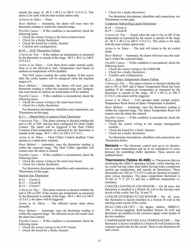
71
outside the range of –40 F (–40 C) to 240 F (115.6 C). Thisalarm is for units with the heat reclaim option only.Action to be Taken — NoneReset Method — Automatic, the alarm will reset once thethermistor reading is within the expected range.Possible Causes — If this condition is encountered, check thefollowing items:• Check the sensor wiring to the heat reclaim board.• Check for a faulty thermistor. • Check the board for a faulty channel.• Confirm unit configuration.th.10 — OAT Thermistor FailureCriteria for Trip — If the outdoor air temperature as measuredby the thermistor is outside of the range –40 F (–40 C) to 240 F(115.6 C).Action to be Taken — Unit shuts down under normal condi-tions or is not allowed to start. Temperature reset based onoutdoor air temperature will be disabled.
The OAT sensor controls the cooler heaters. If this sensorfails, the cooler heaters will be energized when the machinestages to 0.Reset Method — Automatic, the alarm will reset once thethermistor reading is within the expected range and Tempera-ture reset based on outdoor-air temperature will be enabled.Possible Causes — If this condition is encountered, check thefollowing items:• Check the sensor wiring to the main base board.• Check for a faulty thermistor.
For thermistor descriptions, identifiers and connections, seeThermistors on this page.th.11 — Master/Slave Common Fluid ThermistorCriteria for Trip — This alarm criterion is checked whether theunit is ON or OFF and has been configured for Dual ChillerControl. The alarm will be triggered if the Dual ChillerCommon Fluid temperature as measured by the thermistor isoutside of the range –40 F (–40 C) to 240 F (115.6 C).Action to be Taken — Dual Chiller Control disabled. Unitsoperate as a stand-alone machine.Reset Method — Automatic, once the thermistor reading iswithin the expected range. The Dual Chiller algorithm willresume once the alarm is cleared.Possible Causes — If this condition is encountered, check thefollowing items:• Check the sensor wiring to the main base board.• Check for a faulty thermistor.
For thermistor descriptions, identifiers and connections, seeThermistors on this page.Suction Gas Thermistorth.12 — Circuit A th.13 — Circuit B th.14 — Circuit C Criteria for Trip — This alarm criterion is checked whether theunit is ON or OFF. If the suction gas temperature as measuredby the thermistor is outside of the range –40 F (–40 C) to 240 F(115.6 C), the alarm will be triggered.Action to be Taken — The affected circuit shuts downnormally.Reset Method — Automatic, once the thermistor reading iswithin the expected range. The affected circuit will restart oncethe alarm has cleared.Possible Causes — If this condition is encountered, check thefollowing items:• Check the sensor wiring to the EXV board.• Check the board for a faulty channel.
• Check for a faulty thermistor.For thermistor descriptions, identifiers and connections, see
Thermistors on this page.Condenser Subcooling Liquid Thermistorth.18 — Circuit A th.19 — Circuit B Criteria for Trip — Tested when the unit is On or Off. If thetemperature as measured by the sensor is outside of the rangeof –40 F (–40 C) to 240 F (115.6 C). This alarm is for unitswith the heat reclaim option only.Action to be Taken — The unit will return to the air cooledmode.Reset Method — Automatic, the alarm will reset once the read-ing is within the expected range.Possible Causes — If this condition is encountered, check thefollowing items:• Check the sensor wiring to the EMM HR.• Check for a faulty thermistor.• Confirm unit configuration.th.21 — Space Temperature Sensor FailureCriteria for Trip — This alarm criterion is checked whether theunit is ON or OFF and if Space Temperature Reset has beenenabled. If the outdoor-air temperature as measured by thethermistor is outside of the range –40 F (–40 C) to 240 F(115.6 C), the alarm will be triggered.Action to be Taken — Unit operates under normal control.Temperature Reset based on Space Temperature is disabled.Reset Method — Automatic, once the thermistor reading iswithin the expected range. The Space Temperature Reset willresume once the alarm has cleared.Possible Causes — If this condition is encountered, check thefollowing items:• Check the sensor wiring to the energy management
module.• Check the board for a faulty channel.• Check for a faulty thermistor.
For thermistor descriptions, identifiers and connections, seeThermistors below.
Sensors — The electronic control uses up to six thermis-tors to sense temperatures and up to six transducers to sensepressure for controlling chiller operation. These sensors areoutlined below.
Thermistors (Tables 45-46B) — Thermistors that aremonitoring the chiller’s operation include: cooler entering wa-ter, cooler leaving water, dual chiller leaving water, compressorsuction gas temperature, and outside air thermistors. Thesethermistors are 5 kat 77 F (25 C) and are identical in temper-ature versus resistance. The space temperature thermistor is10 k at 77 F (25 C) and has a different temperature vs.resistance.COOLER LEAVING FLUID SENSOR — On all sizes, thisthermistor is installed in a friction fit well in the leaving waternozzle of the cooler. See Fig. 34 and 35.COOLER ENTERING FLUID SENSOR — On all sizes,this thermistor is factory-installed in a friction fit well in theentering water nozzle of the cooler.DUAL CHILLER LWT — On duplex chillers, 30RB315-390, a factory-supplied, field-installed friction fit well andthermistor are installed in the common supply water header ofthe two modules.COMPRESSOR RETURN GAS TEMPERATURE — Thisthermistor is factory-installed in a friction fit well located in thecommon suction line for the circuit. There is one thermistor foreach circuit.
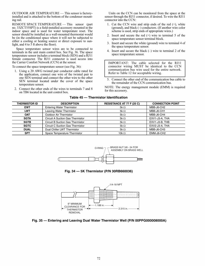
72
OUTDOOR AIR TEMPERATURE — This sensor is factory-installed and is attached to the bottom of the condenser mount-ing rail.REMOTE SPACE TEMPERATURE — This sensor (partno. 33ZCT55SPT) is a field-installed accessory mounted in theindoor space and is used for water temperature reset. Thesensor should be installed as a wall-mounted thermostat wouldbe (in the conditioned space where it will not be subjected toeither a cooling or heating source or direct exposure to sun-light, and 4 to 5 ft above the floor).
Space temperature sensor wires are to be connected toterminals in the unit main control box. See Fig. 36. The spacetemperature sensor includes a terminal block (SEN) and a RJ11female connector. The RJ11 connector is used access intothe Carrier Comfort Network (CCN) at the sensor.To connect the space temperature sensor (see Fig. 36):
1. Using a 20 AWG twisted pair conductor cable rated forthe application, connect one wire of the twisted pair toone SEN terminal and connect the other wire to the otherSEN terminal located under the cover of the spacetemperature sensor.
2. Connect the other ends of the wires to terminals 7 and 8on TB6 located in the unit control box.
Units on the CCN can be monitored from the space at thesensor through the RJ11 connector, if desired. To wire the RJ11connector into the CCN:
1. Cut the CCN wire and strip ends of the red (+), white(ground), and black (–) conductors. (If another wire colorscheme is used, strip ends of appropriate wires.)
2. Insert and secure the red (+) wire to terminal 5 of thespace temperature sensor terminal block.
3. Insert and secure the white (ground) wire to terminal 4 ofthe space temperature sensor.
4. Insert and secure the black (–) wire to terminal 2 of thespace temperature sensor.
5. Connect the other end of the communication bus cable tothe remainder of the CCN communication bus.
NOTE: The energy management module (EMM) is requiredfor this accessory.
Table 45 — Thermistor Identification
IMPORTANT: The cable selected for the RJ11connector wiring MUST be identical to the CCNcommunication bus wire used for the entire network.Refer to Table 12 for acceptable wiring.
THERMISTOR ID DESCRIPTION RESISTANCE AT 77 F (25 C) CONNECTION POINTEWT Entering Water Thermistor 5k MBB-J6-CH2LWT Leaving Water Thermistor 5k MBB-J6-CH1OAT Outdoor Air Thermistor 5k MBB-J6-CH4
SGTA Circuit A Suction Gas Thermistor 5k EXV1-J3-A, THASGTB Circuit B Suction Gas Thermistor 5k EXV1-J3-B, THBSGTC Circuit C Suction Gas Thermistor 5k EXV2-J3-A, THADUAL Dual Chiller LWT Thermistor 5k MBB-J6-CH3SPT Space Temperature Thermistor 10k EMM-J6-CH2
O-RING BRASS NUT 3/8 - 24 FOR ASSEMBLY ON BRASS WELL
6" MINIMUMCLEARANCE FOR
THERMISTORREMOVAL
1.188 in.2.315 in.
1/4-18 NPT
Fig. 34 — 5K Thermistor (P/N 30RB660036)
Fig. 35 — Entering and Leaving Dual Water Thermistor Well (P/N 00PPG000008000A)

73
Table 46A — 5K Thermistor Temperature (°F) vs Resistance
TEMP(F)
RESISTANCE(Ohms)
–25 98,010–24 94,707–23 91,522–22 88,449–21 85,486–20 82,627–19 79,871–18 77,212–17 74,648–16 72,175–15 69,790–14 67,490–13 65,272–12 63,133–11 61,070–10 59,081
–9 57,162–8 55,311–7 53,526–6 51,804–5 50,143–4 48,541–3 46,996–2 45,505–1 44,0660 42,6791 41,3392 40,0473 38,8004 37,5965 36,4356 35,3137 34,2318 33,1859 32,176
10 31,20211 30,26012 29,35113 28,47314 27,62415 26,80416 26,01117 25,24518 24,50519 23,78920 23,09621 22,42722 21,77923 21,15324 20,54725 19,96026 19,39327 18,84328 18,31129 17,79630 17,29731 16,81432 16,34633 15,89234 15,45335 15,02736 14,61437 14,21438 13,82639 13,44940 13,08441 12,73042 12,38743 12,05344 11,73045 11,41646 11,11247 10,81648 10,52949 10,25050 9,97951 9,71752 9,46153 9,21354 8,97355 8,73956 8,51157 8,29158 8,076
TEMP(F)
RESISTANCE(Ohms)
59 7,68660 7,66561 7,46862 7,27763 7,09164 6,91165 6,73566 6,56467 6,39968 6,23869 6,08170 5,92971 5,78172 5,63773 5,49774 5,36175 5,22976 5,10177 4,97678 4,85579 4,73780 4,62281 4,51182 4,40383 4,29884 4,19685 4,09686 4,00087 3,90688 3,81489 3,72690 3,64091 3,55692 3,47493 3,39594 3,31895 3,24396 3,17097 3,09998 3,03199 2,964
100 2,898101 2,835102 2,773103 2,713104 2,655105 2,597106 2,542107 2,488108 2,436109 2,385110 2,335111 2,286112 2,239113 2,192114 2,147115 2,103116 2,060117 2,018118 1,977119 1,937120 1,898121 1,860122 1,822123 1,786124 1,750125 1,715126 1,680127 1,647128 1,614129 1,582130 1,550131 1,519132 1,489133 1,459134 1,430135 1,401136 1,373137 1,345138 1,318139 1,291140 1,265141 1,240142 1,214
TEMP(F)
RESISTANCE(Ohms)
143 1,190144 1,165145 1,141146 1,118147 1,095148 1,072149 1,050150 1,029151 1,007152 986153 965154 945155 925156 906157 887158 868159 850160 832161 815162 798163 782164 765165 750166 734167 719168 705169 690170 677171 663172 650173 638174 626175 614176 602177 591178 581179 570180 561181 551182 542183 533184 524185 516186 508187 501188 494189 487190 480191 473192 467193 461194 456195 450196 445197 439198 434199 429200 424201 419202 415203 410204 405205 401206 396207 391208 386209 382210 377211 372212 367213 361214 356215 350216 344217 338218 332219 325220 318221 311222 304223 297224 289225 282

74
Table 46B — 5K Thermistor Temperature (°C) vs Resistance/Voltage
Service Test — Main power and control circuit powermust be on for Service Test.
The Service Test function is used to verify proper operationof various devices within the chiller, such as condenser fan(s),compressors, minimum load valve solenoid (if installed),cooler pump(s) and remote alarm relay. This is helpful duringthe start-up procedure to determine if devices are installedcorrectly. See Fig. 37-41 for 30RB wiring diagrams.
To use the Service Test mode, the Enable/Off/Remote Con-tact switch must be in the OFF position. Use the display keys tomove to the Service Test mode. The items are described in theService Test table. There are two sub-modes available. ServiceTestT.REQ allows for manual control of the compressorsand minimum load control. In this mode the compressors willoperate only on command. The capacity control and head pres-sure control algorithms will be active. The condenser fans will
operate along with the EXVs. There must be a load on thechiller of operate for an extended period of time. All circuitsafeties will be honored during the test. Service TestQUICallows for test of EXVs, condenser fans, pumps, low ambienthead pressure control speed control, crankcase and cooler heat-ers, and status points (alarm relays, running status and chillercapacity). This mode allows for the testing of non-refrigerationitems. If there are no keys pressed for 5 minutes, the active testmode will be disabled.
To enter the Manual Control mode, the Enable/Off/RemoteContact switch must be in the OFF position. Move the LED tothe Service Test mode. Press to access TEST. Press
to access T.REQ. Press and the displaywill show OFF. Press and OFF will flash. Enter thepassword if required. Use either arrow key to change the
TEMP(C)
RESISTANCE(Ohms)
–32 100,260–31 94,165–30 88,480–29 83,170–28 78,125–27 73,580–26 69,250–25 65,205–24 61,420–23 57,875–22 54,555–21 51,450–20 48,536–19 45,807–18 43,247–17 40,845–16 38,592–15 38,476–14 34,489–13 32,621–12 30,866–11 29,216–10 27,633
–9 26,202–8 24,827–7 23,532–6 22,313–5 21,163–4 20,079–3 19,058–2 18,094–1 17,1840 16,3251 15,5152 14,7493 14,0264 13,3425 12,6966 12,0857 11,5068 10,9599 10,441
10 9,94911 9,48512 9,04413 8,62714 8,231
TEMP(C)
RESISTANCE(Ohms)
15 7,85516 7,49917 7,16118 6,84019 6,53620 6,24621 5,97122 5,71023 5,46124 5,22525 5,00026 4,78627 4,58328 4,38929 4,20430 4,02831 3,86132 3,70133 3,54934 3,40435 3,26636 3,13437 3,00838 2,88839 2,77340 2,66341 2,55942 2,45943 2,36344 2,27245 2,18446 2,10147 2,02148 1,94449 1,87150 1,80151 1,73452 1,67053 1,60954 1,55055 1,49356 1,43957 1,38758 1,33759 1,29060 1,24461 1,200
TEMP(C)
RESISTANCE(Ohms)
62 1,15863 1,11864 1,07965 1,04166 1,00667 97168 93869 90670 87671 83672 80573 77574 74775 71976 69377 66978 64579 62380 60281 58382 56483 54784 53185 51686 50287 48988 47789 46690 45691 44692 43693 42794 41995 41096 40297 39398 38599 376
100 367101 357102 346103 335104 324105 312106 299107 285
Fig. 36 — Typical Remote Space Temperature Sensor Wiring
7
8
TB6SENSEN
SENSOR
ENTERENTER ENTER
ENTER
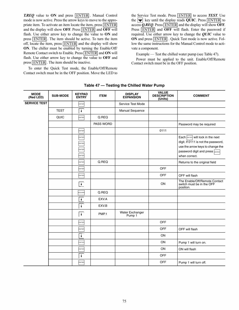
75
T.REQ value to ON and press . Manual Controlmode is now active. Press the arrow keys to move to the appro-priate item. To activate an item locate the item, press and the display will show OFF. Press and OFF willflash. Use either arrow key to change the value to ON andpress . The item should be active. To turn the itemoff, locate the item, press and the display will showON. The chiller must be enabled by turning the Enable/Off/Remote Contact switch to Enable. Press and ON willflash. Use either arrow key to change the value to OFF andpress . The item should be inactive.
To enter the Quick Test mode, the Enable/Off/RemoteContact switch must be in the OFF position. Move the LED to
the Service Test mode. Press to access TEST. Usethe key until the display reads QUIC. Press toaccess Q.REQ. Press and the display will show OFF.Press and OFF will flash. Enter the password ifrequired. Use either arrow key to change the QUIC value toON and press . Quick Test mode is now active. Fol-low the same instructions for the Manual Control mode to acti-vate a component.
Example — Test the chilled water pump (see Table 47). Power must be applied to the unit. Enable/Off/Remote
Contact switch must be in the OFF position.
Table 47 — Testing the Chilled Water Pump
ENTER
ENTERENTER
ENTERENTER
ENTER
ENTER
ENTERENTER
ENTERENTER
ENTER
MODE(Red LED) SUB-MODE KEYPAD
ENTRY ITEM DISPLAYEXPANSION
VALUEDESCRIPTION
(Units)COMMENT
SERVICE TEST Service Test Mode
TEST Manual Sequence
QUIC Q.REQ
PASS WORD Password may be required
0111
Each will lock in the next
digit. If 0111 is not the password,
use the arrow keys to change the
password digit and press
when correct.
Q.REQ Returns to the original field
OFF
OFF OFF will flash
ONThe Enable/Off/Remote Contact switch must be in the OFFposition.
Q.REQ
EXV.A
EXV.B
PMP.1 Water ExchangerPump 1
OFF
OFF OFF will flash
ON
ON Pump 1 will turn on.
ON ON will flash
OFF
OFF Pump 1 will turn off.
ENTER
ENTER
ENTER
ENTER
ENTER
ENTER
ENTER
ENTER
ENTER
ENTER
ENTER
ENTER
ESCAPE
ENTER
ENTER
ENTER
ENTER
ENTER

76
Test the condenser fans, cooler pump(s) and alarm relay bychanging the item values from OFF to ON. These discreteoutputs are then turned off if there is no keypad activity for10 minutes. Test the compressor and minimum load valve sole-noid (if installed) outputs in a similar manner. The minimumload valve solenoids will be turned off if there is no keypadactivity for 10 minutes. Compressors will stay on until theoperator turns them off. The Service Test mode will remainenabled for as long as there is one or more compressorsrunning. All safeties are monitored during this test and will
turn a compressor, circuit or the machine off if required. Anyother mode or sub-mode can be accessed, viewed, or changedduring the Manual Control mode only. The STAT item (RunStatusVIEW) will display “0” as long as the Service mode isenabled. The TEST sub-mode value must be changed back toOFF before the chiller can be switched to Enable or Remotecontact for normal operation.NOTE: There may be up to a one-minute delay before theselected item is energized.
LEGEND FOR FIG. 37-41ALM R — Alarm RelayALT R — Alert RelayCB — Circuit BreakerCL-HT — Cooler HeaterCWFS — Chilled Water Flow SwitchDLSV — Discharge Line Soleniod ValveDPT — Discharge Pressure TransducerECA — Entering CondenserEMM — Energy Management ModuleEXV — Electronic Expansion ValveFIOP — Factory-Installed OptionFM — Fan MotorHOA — Hand/Off/AutoHOA-A — Hand/Off/Auto, Auto SettingLCW — Leaving Condenser WaterLLSV — Liquid Line Soleniod ValveLWT — Leaving Water TemperatureMLV — Minimum Load ValveMM — Low Ambient Temperature Head Pressure ControlOAT — Outdoor Air TemperaturePDP — Pumpdown PressurePMP — Pump, Chilled WaterPMPI — Chilled Water Pump InterlockRDY R — Ready RelayRRB — Reverse Rotation BoardRUN R — Run RelaySGT — Suction Gas ThermistorSHD R — Shutdown RelaySPM — Scroll Protection ModuleSPT — Suction Pressure TransducerTB — Terminal BlockTRAN — TransformerUPC — Unitary Protocol Controller
Terminal Block Connection
Marked Terminal
Unmarked Terminal
Unmarked Splice
Factory Wiring
Optional Wiring
Indicates common potential.Does not represent wiring.
FIOP or Accessory
Wire Tag

77
? ? ? ? ? ? ? ??
? ???? ? ? ? ? ? ? ???????????????????????
? ? ? ??
? ? ? ? ? ???? ? ? ? ? ? ? ???????????????????????
???????
??
??
??
??
??
??
??
??
?
??? ???
??? ???
?? ?? ??
???
??
??
??
??
??
??
??
??
?
??? ???
??? ???
?? ?? ?? ??
??????? ?????????
??? ?????????????????
??? ???
??? ?????????????
?????????????????????????
??? ?????????
?????
?
?
?
?
??
?
?
?
?
???
???
???
????
?
?
?
???????
?????
?
?
?
?
??
?
?
?
?
???????
???
???
?
??
??
???
?
?
?
???
???
???
???
???
???
?
?
?
?
?
???
????
???
?????
???
????
???
???
???
???
???
???
??
??????????????
???
??
???
???
???
???
???
?
?
?
?
?
?
????????????????????
???
???
???
???
???
? ? ? ? ? ?
???????????????
??? ??? ??? ??? ???
???
???
???
???
???
?
?
?
?
?
?
???????????
??????
???
???
???
???
???
???
???
???
???
?
?
?
?
??
??
??
??
??
??
??
??
??
??
?
?
?
?
???
???
??? ????
?
?
?
??
??
???
?
?
?? ???
???
??? ????
?
?
?
??
??
???
?
?
?? ???
???
??? ????
?
?
?
??
??
???
?
?
?? ???
???
??? ????
?
?
?
??
??
???
????
? ??
??
??
??
??
??
??
??
??
??
??
??
??
??
?
?????
???
?
???
??? ??
??
??
??
??
??
??
??
??
??
??
??
??
???? ????
???
??
??
??
???
???
???
???
???
???
??
???
?
??
??
?????
???
???
??
??
??
???
???
???
????????????
? ??
?? ?
???
???
???
???
????????????
????????????????????????????
????
????
??????
???
?
????
?????????????
??
??
??
??
??
?
?
???
??
??
?? ???
??
??
??
??
??
?
?
???
??
??
??
??
??
??
??
??
?
????????
???
???
???
???
???
???
?????
?????
????
????
?????
????
????
?? ??
???
???
???
???
?????
?????
??????? ??
?????
????
?????
?????
?????
?????
????
????
???
???
???
???
???
???
?
?
?
?
?
?
?
?
?
?
?
?
?
?
?
?
??
??
??
??
??
??
??
??
?
?
?
?
?
?
?
?
??
??
??
??
??
??
??
??
???????
???
???????
???
???????
???
???????
???
???
???
?????????????????????????????????????
????
? ?
?????
? ?
?
?
??
?????????????
???
???
???
??
?
????????
???
?
?
?
?
?
?
???
?
????????????????
??
??
???
???
????????
??????????????
?
?
?
?
?
?
?
??
?
?
?
?? ?
?? ?
?? ?
?? ?
?
?
?
?
?
?
?
?
??
??
??
??
??
??
??
??
?
?
?
?
?
?
??
?
?
???
?
??
???
??
?
?
??
?? ?
?
?
??
???
???
?? ?
?
???
???
?? ?
??
? ? ??
?????
????
???
???
? ?
????
????
??
???
???
????????????????
???????????????
????????????????????
?????????
???????????????
???????????????
??
????
???
?
????
??
? ???
???
???
???
?
????
???
?? ?
??
????
???
???
??
? ?
??
? ?
? ??
??????????????
???
???
???????????????????????????????????????????????????????????????????????????????????????????????
???
??????
?
???
?
??????
??????
???
????
??????
??? ?
???
??? ?
????
???
??
? ???
?? ?
???
? ????
??????
????
????? ???
???
?????????????
?????????
?
?
?????????????
?????????
?
?
??
??????
????????????
???
?????? ?
???
??? ?
????????????
?
?
?
?
?
?
???
???
??
?
?????????
???
??
?? ?
??
??
??
??
?
?? ??
?? ?? ???
?????????
?
?
?
?
?
?
?
?
?
?
?
?
?
?
?
?
?
?
?
?
?
?
?
?
????
????
?
? ?
?
????????
???????????????????
???????????????????????????
?
?
??? ????
? ?
???
?
??? ? ??????
????
???
???
?????
??? ????????????????????????????????????????????????????????????????????????????????????????????
??
??
???
???
???
? ??
?? ?
???
???
???
???
????????????????????????????????
??
??
??
??
?
??
?
??
?
??
?
??
?
??
?
??
??
??
??
?
????
? ??
?? ?
???
???
???
?
???
?
?
??
?
?
??
?
?
?
??
?
?
?
?
?
?
??
?
?
?
?
?
?
??
?
?
?
?
?
?
?
?
?
??
??
??
????
????????
???????????????????????????????????????????
??????????????????
????????????????????????
?????????????????????????
?
?
?
??????
????
?
?
???
???????????????????
???
???
???
?????????????
?????????
??????????????
??????????
????????????
??????????
???????
???
???
???
??????
??
??
??
??
?????????????????????????
???????????????????????????????????????????????????????????????
???
??????????????????????????????
?????
?????
???????????????????????????????????????????????????????????????????????????????????????????????
Fig. 37 — Control Schematic, 30RB060-080a30-4619

78
? ? ? ? ? ? ? ??
? ???? ? ? ? ? ? ? ???????????????????????
? ? ? ??
? ? ? ? ? ???? ? ? ? ? ? ? ???????????????????????
???????
??
??
??
??
??
??
??
??
?
??? ??? ???
??? ??? ???
?? ?? ?? ??
??????? ?????????
??????????????????????????????????????
?????????????????????????????????????
??? ??????????????????????????????????
??? ?????????????
?????????????????????????????????????
??? ??????????????????????????????????
??? ??????????????????????????????????
??? ?????????????????
???
??
??
??
??
??
??
??
??
?
??? ??? ???
??? ??? ???
?? ?? ?? ?? ??
???
??
??
??
??
??
??
??
??
?
??? ??? ??? ???
??? ??? ???
?? ?? ?? ?? ??
???????
??
??
??
??
??
??
??
??
?
??? ??? ??? ???
??? ??? ??? ???
?? ?? ?? ?? ?? ??
?????
?
?
?
?
??
?
?
?
?
???
???
???
???
???????
?????
?
?
?
?
??
?
?
?
?
???????
???
???
?
? ??
?? ?
??
???
???
???
??
???
?
?
?
???
???
???
???
???
???
?
?
?
?
?
?
?
?
???
???
???
?????
???
????
???
???
???
???
???
???
??
??????????????
???
??
???
???
???
???
???
???
???
???
?
?
?
?
?
?
????????????????????
???
???
???
???
???
? ? ? ? ? ?
???????????????
??? ??? ??? ??? ???
???
???
???
???
???
?
?
?
?
?
?
???????????
??????
???
???
???
???
???
???
???
???
???
??
??
??
??
??
??
??
??
??
??
?
?
?
?
???
???
??? ????
?
?
?
??
??
???
?
?
?? ???
???
??? ????
?
?
?
??
??
???
?
?
?? ???
???
??? ????
?
?
?
??
??
???
?
?
?? ???
???
??? ????
?
?
?
??
??
???
????
? ??
??
??
??
??
??
??
??
??
??
??
??
??
??
?
?????
???
?
???
??? ??
??
??
??
??
??
??
??
??
??
??
??
??
???? ????
???
??
??
??
???
???
???
???
???
???
??
???
?
??
??
?????
???
???
??
??
??
???
???
???
????????????
? ??
?? ?
???
???
???
???
????????????
????
????
??????
???
?
????
?????????????
??
??
??
??
??
?
?
???
??
??
?? ???
??
??
??
??
??
?
?
???
??
??
??
??
??
??
??
??
?
????????
?
?
?
?
?
?
?
?
??
??
??
??
??
??
??
??
?
?
?
?
?
?
?
?
??
??
??
??
??
??
??
??
???????
???
???????
???
???????
???
???????
???
???
???
????
?
?????
? ?
?
?
??
?????
???
?????
???????
???
???
?
????????????????
???????
???
???????
???
???????
???
?
?
?
???
?
?
??
?
?
?
?
??
?
?
?
?
?
?
?
?
?
?
?
?
??
?
?
?
?
?
?
??
?
??
??
??
????
????????
???????????????????????????????????????????
??????????????????
????????????????????????
?????????????????????????
??????
????
?
?
???
???????????????????
??
??
??
??
??
??
??
??
??
??
?????????????
?????????????????????????????????????
?
???????????????????????????????????????????????????????????????????????????????????????????????
??
??
???
???
????????
??????????????
?
?
?
?
?
?
?
??
?
?
?
?? ?
?? ?
?? ?
?? ?
?
?
?
?
?
?
?
?
??
??
??
??
??
??
??
??
?
?
?
?
?
?
??
?
?
???
?
??
???
??
?
?
??
?? ?
?
?
??
?? ?
?
???
???
?? ?
??
? ? ??
?????
????
???
???
? ?
????
????
??
???
???
??
???????????????
???????????????
??
????
???
?
? ??
??????????????
???
???
???
??????
?
???
?
??????
??????
????
??????
???
????
?? ?
??
? ???
???
???
? ????
??????
????
???
???
??
????
???
?? ?
?????????? ??
???
?????????????
????????????????????????????
????
????? ???
???
????
??
????
???
?? ?
???
?
??
??????
???
???
?????????????
???????????????
?????????????
???????????????
??? ?
???
??? ?
?????????????
?????????
?
?
?????????????
?????????
?
?
????????????
???
?????? ?
???
??? ?
????????????
? ?
??
? ?
??
? ?
???
??
?? ?
??
??
??
??
?
???
???
???
????
????
?????
?????
????
?????
?????
?????
?????
????
????
???
???
????
?
?
?
?
?
???
???
?
?
?
?????????
?
?
?
?
???
????????
????
?? ????? ????????
???
???
?? ??
?? ?? ???
?????????
?
?
?
?
?
?
????
????
??
?
?
?
?
?
?
?
?
?
?
?
?
?
?
?
?
?
?
?
?
?
?
?
?
?
?
?
?
?
?
?
?
?
?
?
?
?
?
?
??
?
??? ????
???????????????????????????
???????????????????????????
?
? ?
?
? ?
???
?
????????
???????? ???
????? ??? ? ?
?????
??? ????????????????????????????????????????????????????????????????????????????????????????????
???????? ???
?????
??
??
???
???
???
? ??
?? ?
???
???
???
???
????????????????????????????????
??
??
??
??
?
??
?
??
?
??
?
??
?
??
?
??
??
??
??
?
???
???
??
??
??
??
??
?
???
??????
??????
???
?
?
?
???????
?
?????
?
???
??????
????????????
??????
?????????????????????????????????????
??
??
??
??
??
??
??
??
??
??
?????????
????????????????????????
????????????
??????????
???????
???
???
???
??????
?????????????????????????
????
??
??
??
??
???????????????????????????????????????????????????????????????
???
??????????????????????????????
?????
?????
????????????????????????????????????????????????????????????????????????????????????????????????
Fig. 38 — Control Schematic, 30RB090-150 a30-4620

79
??????? ?????????
??? ?????? ?????? ?????? ?????? ?????? ???
???????
??
??
??
??
??
??
??
??
??? ??? ??? ??? ???
??? ??? ??? ??? ????
?? ?? ?? ?? ?? ?? ??
???
??
??
??
??
??
??
??
??
??? ??? ??? ??? ??? ????
??? ??? ??? ??? ???? ????
?? ?? ?? ?? ?? ?? ?? ??
??????? ?????????
??? ????????????????????????
??? ??????????????????????
??? ??????????????????????
??? ????????????????????????
??? ??????????
??? ??????????
? ? ? ??
? ? ? ? ? ???? ? ? ? ? ? ? ???????????????????????
? ? ? ? ? ? ? ??
? ???? ? ? ? ? ? ? ???????????????????????
? ? ? ? ??
? ? ? ? ???? ? ? ? ? ? ? ???????????????????????
?????
?
?
?
?
??
?
?
?
?
???
???
???
???
???????
?????
?
?
?
?
??
?
?
?
?
???????
???
???
?
? ??
?? ?
??
???
???
??? ?????
?
?
?
???
???
???
???
???
???
?
?
?
?
?
?
?
?
???
???
???
?????
???
????
???
???
???
???
???
???
??
??????????????
???
??
???
???
???
???
???
???
???
???
?
?
?
?
?
?
????????????????????
???
???
???
???
???
? ? ? ? ? ?
???????????????
??? ??? ??? ??? ???
???
???
???
???
???
?
?
?
?
?
?
???????????
??????
???
???
???
???
??? ???
???
???
???
??
??
??
??
??
??
??
??
??
??
?
?
?
?
???
???
??? ????
?
?
?
??
??
???
?
?
?? ???
???
??? ????
?
?
?
??
??
???
?
?
?? ???
???
??? ????
?
?
?
??
??
???
?
?
?? ???
???
??? ????
?
?
?
??
??
???
????
? ??
??
??
??
??
??
??
??
??
??
??
??
??
??
?
?????
???
?
???
??? ??
??
??
??
??
??
??
??
??
??
??
??
??
???? ????
???
??
??
??
???
???
???
???
???
???
??
???
?
??
??
?????
???
???
??
??
??
???
???
???
????????????
? ??
?? ?
???
???
???
???
????????????
????
????
??????
???
?
????
?????????????
??
??
??
??
??
?
?
???
??
??
?? ???
??
??
??
??
??
?
?
???
??
??
??
??
??
??
??
??
?
??????????
?
?
?
?
?
?
?
?
??
??
??
??
??
??
??
??
?
?
?
?
?
?
?
?
??
??
??
??
??
??
??
??
???????
???
???????
???
???????
???
???????
???
???
???
????
??
?
??
?????
???
?????
???????
???
???
?
????????????????
???????
???
??
???
?
??
??
?????
???
???
??
??
??
???
???
???
??????????
?
?
?
?
?
?
?
?
??
??
??
??
??
??
??
??
?
?
?
?
?
?
?
?
??
??
??
??
??
??
??
??
???????
???
???????
???
???????
???
???????
???
????? ?
???????
???
???????
???
?
?
?
?
?
?
?
?
?
?
?
?
?
?
?
?
??
?
?
?
?
?
???????????????????????????
?
?
? ?
??
???
?
?
??
?
?
?
?
??
?
?
?
?
?
?
?
?
?
?
?
?
??
?
?
?
?
?
?
?
?
?
??
??
??
????
????????
???????????????????????????????????????????
??????????????????
????????????????????????
?????????????????????????
??????
????
?
?
???
?????????????????????????
???????
?????????????????????????????????????
?
???????????????????????????????????????????????????????????????????????????????????????????????
??
??
???
???
????????
??????????????
?
?
?
?
?
?
?
??
?
?
?
?? ?
?? ?
?? ?
?? ?
?
?
?
?
?
?
?
?
??
??
??
??
??
??
??
??
?
?
?
?
?
?
??
?
?
???
?
??
???
??
?
?
??
?? ?
?
?
??
?? ?
?
???
???
?? ?
??
? ? ??
?????
????
???
???
? ?
????
????
??
???
???
??
???????????????
???????????????
??
????
???
?
? ??
??????????????
???
???
???
??????
?
???
?
??????
??????
????
??????
????
???
???
? ?
????
???
???
???
????
???
??
????
???
???
? ????
??????
??????? ??
????????????????????????????
????
????? ???
???
????
??
??? ?
???
???
???
?
??
??????
???
???
????????????? ???????
?????????
????????????? ???????
?????????
??? ?
???
??? ?
?????????????
?????????
?
?
?????????????
?????????
?
?
????????????
???
?????? ?
???
??? ?
????????????
?
?
?
?
?
?
?
?
?
?
?
?
?
?
?
?
?
?
?
?
?
?
?
?
??
? ?
??
? ?
???
??
?? ?
??
??
??
??
?
???
???
???
???
????
????
?????
?????
????
?????
?????
?????
?????
????
????
???
???
???
????
?
?
?
?
?
???
???
?
?
?
?????????
?
?
?
?
???
????????
????
?? ????? ????????
???
???
?? ??
?? ?? ???
?????????
?
?
?
?
????
????
??
?
?
?
?
?
?
?
?
?
?
?
?
?
?
?
??? ??
??
???????????????????????????
?
?
? ?
?
????????
???????? ???
????? ??? ? ?
?????
??? ????????????????????????????????????????????????????????????????????????????????????????????
???????? ???
?????
??
??
???
???
???
? ??
?? ?
???
???
???
???
????????????????????????????????
??
??
??
??
?
??
?
??
?
??
?
??
?
??
?
??
??
??
??
?
???
???
??
??
??
??
??
?
???
??????
??????
???
?
?
?
???????
?
?????
?
???
??????
????????????
??????
???????????????????
??
??
??
??
??
??
??
??
??
??
?????????
??????????????
??????????
????????????
??????????
???????
???
???
???
??????
????
??
??
??
??
?????????????????????????
???????????????????????????????????????????????????????????????
???
??????????????????????????????
?????
?????
??????????????????????????????????????????????????????????????????????????????????????????????
Fig. 39 — Control Schematic, 30RB160-190 a30-4622

80
???????????
??????? ?????????
??? ??????????????????????????????
??? ??????????????????????????????
??? ??????????????????????????????
??? ??????????????????????????????
??? ??????????????????????????????
??? ??????????????????????????????
??? ?????????????????
??? ?????????????????
???????
??
??
??
??
??
??
??
??
??? ??? ??? ??? ??? ????
??? ??? ??? ??? ???? ????
?? ?? ?? ?? ?? ?? ?? ?? ??
?????????????????????????
??????? ?????????
??? ????
??? ???
??? ???
??? ???
??? ????
??? ????
???
??
??
??
??
??
??
??
??
??? ??? ??? ??? ??? ???? ????
??? ??? ??? ??? ???? ???? ????
?? ?? ?? ?? ?? ?? ?? ?? ?? ??
???
??
??
??
??
??
??
??
??
??? ??? ??? ??? ??? ???? ???? ????
??? ??? ??? ??? ???? ???? ???? ????
?? ?? ?? ?? ?? ?? ?? ?? ?? ?? ??
???
??
??
??
??
??
??
??
??
??? ??? ??? ??? ??? ???? ???? ???? ????
??? ??? ??? ??? ???? ???? ???? ???? ????
?? ?? ?? ?? ?? ?? ?? ?? ?? ?? ?? ??
? ? ? ??
? ? ? ? ? ???? ? ? ? ? ? ? ?
??????????????????????
?????????????????? ?????????
???
????????????????????????????????????????????
???
????????????????????????????????????????????
???
????????????????????????????????????????????
???
????????????????????????????????????????????
??? ????????????????????
??? ????????????????????
? ? ? ??
? ? ? ? ? ???? ? ? ? ? ? ? ???????????????????????
? ? ? ? ? ? ? ??
? ???? ? ? ? ? ? ? ???????????????????????
? ? ? ? ? ? ??
? ? ???? ? ? ? ? ? ? ???????????????????????
? ? ? ? ??
? ? ? ? ???? ? ? ? ? ? ? ???????????????????????
?????
?
?
?
?
??
?
?
?
?
???
???
???
???
???????
?????
?
?
?
?
??
?
?
?
?
???????
???
???
?
? ??
?? ? ??
???
???
???
??
???
?
?
?
???
???
???
???
???
???
?
?
?
?
?
?
?
?
???
???
???
?????
???
????
???
???
???
???
???
???
??
??????????????
???
??
???
???
???
???
???
???
???
???
?
?
?
?
?
?
????????????????????
???
???
???
???
???
? ? ? ? ? ?
???????????????
??? ??? ??? ??? ???
???
???
???
???
???
?
?
?
?
?
?
???????????
??????
???
???
???
???
???
???
???
???
???
??
??
??
??
??
??
??
??
??
??
?
?
?
?
???
???
??? ????
?
?
?
??
??
???
?
?
?? ???
???
??? ????
?
?
?
??
??
???
?
?
?? ???
???
??? ????
?
?
?
??
??
???
?
?
?? ???
???
??? ????
?
?
?
??
??
???
????
? ??
??
??
??
??
??
??
??
??
??
??
??
??
??
?
?????
???
?
???
??? ??
??
??
??
??
??
??
??
??
??
??
??
??
???? ????
???
??
??
??
???
???
???
???
???
???
??
???
?
??
??
?????
???
???
??
??
??
???
???
???
????????
???
? ??
?? ?
???
???
???
???
????????
???
????
???
?
??????
???
?
????
?????????????
??
??
??
??
??
?
?
???
??
??
?? ???
??
??
??
??
??
?
?
???
??
??
??
??
??
??
??
??
?
??????????
?
?
?
?
?
?
?
?
??
??
??
??
??
??
??
??
?
?
?
?
?
?
?
?
??
??
??
??
??
??
??
??
???????
???
???????
???
???????
???
???????
???
???
???
????
??
?
??
?????
???
?????
???????
???
???
?
????????????????
???????
???
??
???
?
??
??
?????
???
???
??
??
??
???
???
???
??????????
??????????????
?
?
?
?
?
?
?
?
??
??
??
??
??
??
??
??
?
?
?
?
?
?
?
?
??
??
??
??
??
??
??
??
???????
???
???????
???
???????
???
???????
???
???????
???
???????
???
???
?
? ???
?
?
?
?
??
?
?
?
?
???
???
???
????????
?
?
?
?
?
???????
???
?????????????
?
??????????????
??????????
????
????
???? ????
??
??
??
???
???
???
???????
???
???????
???
??
??
??
??
??
??
???
???
???
??????????
?
?
?
?
?
?
?
?
??
??
??
??
??
??
??
??
?
?
?
?
?
?
?
?
??
??
??
??
??
??
??
??
???????
???
???????
???
???????
???
???????
???
????
? ?
???????
???
???????
???
??
??
??
???
???
???
?
?
?
?
?
?
?
?
?
?
?
?
?
?
?
?
?
?
?
?
????????
???????????????????
?????
? ????????????????????????????????????????????????
????
? ?
????????
???????????????????
??
?
?
?
?
?
?
?
?
?
?
?
?
?
?
?
?
?
????????
???
?
?
? ?
?
??
?
?
??
?
?
???
?
?
??
?
?
?
?
??
?
?
?
?
?
?
?
?
?
?
?
?
??
?
?
?
?
?
?
?
?
?
??
??
??
????
??????????
???????????????????????????????????????????
??????????????????
????????????????????????
?????????????????????????
??????
????
?
?
???
???????????????????
?????????????
?????????????????????????????????????
???????????????????????????????????????????????????????????????????????????????????????????????
?
?
?
???
???
???
????
?
? ?
?
? ??
??
?
?
?
?
???
???
???
????
?
? ?
?
? ??
??
?
??
?????
?????
???
??
??
???
???
????????
??????????????
?
?
?
?
?
?
?
??
?
?
?
?? ?
?? ?
?? ?
?? ?
?
?
?
?
?
?
?
?
??
??
??
??
??
??
??
??
?
?
?
?
?
?
??
?
?
???
?
??
???
??
?
?
??
?? ?
?
?
??
?? ?
?
???
???
?? ?
??
? ? ??
?????
????
???
???
? ?
????
????
??
???
???
??
???????????????
???????????????
??
????
???
?
? ??
??????????????
???
???
???
??????
?
???
?
??????
??????
????
??????
????
???
???
??
????
?? ?
???
? ??
????
???
??
????
?? ?
???
? ????
??????
??????? ??
????????????????????????????
????
????? ???
???
????
??
????
???
???
? ??
?
??
??????
???
???
?????????????
???????????????
?????????????
???????????????
??? ?
???
??? ?
?????????????
?????????
?
?
?????????????
?????????
?
?
????????????
???
?????? ?
???
??? ?
????????????
?
?
?
?
?
?
?
?
?
?
?
?
?
?
?
?
?
?
?
?
?
?
?
?
??
? ?
??
? ?
???
??
?? ?
??
??
??
??
?
????????
???????????????????
???
???
???
???
????
????
?????
?????
????
?????
?????
?????
?????
????
????
???
???
???
????
?
?
?
?
?
???
???
?
?
?
?????????
?
?
?
?
?
?
???
???
?????
?????
????
????
????
?? ??
???
???
???
???
?????
?????
???
???
?? ??
?? ?? ???
?????????
?
?
?
?
????
????
?
?
??
?
?
?
?
?
?
?
?
?
?
?
?
?
?
?
??? ????
?
?
? ?
?
?
?
?
??
?
???
????????????????????????????????????????????????????????????????????????????????????????????
???????? ???
?????
????????????????????????????????
??
??
???
??????
? ??
?? ?
???
???
???
???
??
??
??
??
?
??
?
??
?
??
?
??
?
??
?
??
??
??
??
?
???
???
??
??
??
??
??
?
???
??????
????
??
???
?
?
?
???????
??????
?
???
??????
????????????
??????
???????????????????
??
??
??
??
??
??
??
??
??
??
?
? ???
??????
????
?
??????
?????
?????????????????????????????????????
??
??
??
??
??
??
??
??
??
??
??
??
??????????????
??????????
????????????
??????????
???????
???
???
???
??????
?????????
????
??
??
??
??
?????????????????????????
???????????????????????????????????????????????????????????????????????????????????????????????
Fig. 40 — Control Schematic, 30RB210-300 a30-4622

81
? ? ? ? ?
?
? ? ? ? ?
?
?
?
?
?
?
?
? ? ?
???
???
???
? ? ? ? ? ? ? ? ? ? ? ? ?? ? ? ? ? ? ? ? ? ? ? ?
?
?? ?
?
? ? ?
? ? ?
?? ?
?
?
?
?
?
?
? ? ?
???
???
???
???
???
???
?
???
?? ??
? ? ? ? ? ? ? ? ?? ? ? ? ? ? ? ?? ? ? ? ?? ? ? ? ?? ? ? ? ? ?
? ? ? ? ? ? ? ?
?
?
? ? ? ? ?
? ? ?
? ? ?
?
?
?
? ? ? ?
?
?
?
? ?
? ?
? ? ?
? ? ?
? ? ?
?
?
?
????
????
??? ?
????
?? ?
?
?
?
? ? ? ? ?
?
?
? ? ? ? ? ? ? ? ? ? ? ? ? ? ? ? ? ? ? ? ?? ? ? ? ? ?
? ? ? ? ? ? ? ? ? ? ? ? ? ? ? ? ? ? ? ? ?
? ? ? ? ? ? ? ? ? ? ? ? ? ? ? ? ? ? ? ? ? ? ? ? ? ? ? ? ?
? ? ? ? ? ? ? ? ? ? ? ? ? ? ? ? ? ? ? ? ? ? ? ? ? ? ? ?
?
?
? ? ? ? ?
? ? ?
? ? ?
?
?
?
? ? ? ?
? ? ?? ? ?? ? ?
? ? ? ? ?
????
?
?
? ? ? ??
?
? ? ? ? ? ? ? ? ? ? ? ? ? ?? ? ? ? ? ?
? ?
? ? ? ? ?
???
? ?
? ?
? ? ? ? ?
???
? ?
? ?? ? ? ? ?
???
???
? ?
? ?
? ? ? ? ?
???
???
? ?
? ?
? ? ? ? ?
???
???
? ?
? ?
? ? ? ? ?
???
???
? ?
? ?
? ? ? ? ?
???
???
? ?
? ?
? ? ? ? ?
???
???
? ?
?
? ? ? ? ?
? ? ? ? ? ? ?
? ? ?? ? ? ? ? ?? ? ? ?
? ? ?? ? ?
? ? ?
???
?????
????
?
? ? ?
? ?
?
?
? ? ? ? ? ? ? ? ? ? ? ?? ? ? ? ? ? ? ? ? ? ? ?? ? ? ? ? ? ? ? ? ? ? ?
? ? ? ? ? ? ? ? ?? ? ? ? ? ? ? ? ? ? ? ? ? ?
? ? ?
???
? ? ?
? ? ? ? ?
? ? ?
???????
? ? ? ?
? ? ?? ? ? ? ? ? ? ? ?? ? ? ? ? ? ?? ? ? ? ? ? ? ? ? ? ? ? ?
? ?? ? ?
?? ? ?? ? ? ?
? ? ?? ? ? ? ? ? ? ? ?? ? ? ? ? ? ?? ? ? ? ? ? ? ? ? ? ? ? ?
? ?? ? ?
?? ? ?? ? ? ?
? ? ?
? ? ? ? ? ? ? ? ?? ? ? ? ? ? ?? ? ? ? ? ? ? ? ? ? ? ? ? ? ?
? ?? ? ?
? ? ?
? ? ? ? ?
? ? ? ? ?
? ? ?
? ? ? ? ?
? ? ? ? ? ? ? ? ?? ? ? ? ? ? ?? ? ? ? ? ? ? ? ? ? ? ? ? ? ?
? ? ? ? ? ? ? ? ? ? ? ? ? ? ? ? ? ? ? ?
? ? ? ? ? ? ? ? ?? ? ? ? ? ? ?? ? ? ? ? ? ? ? ? ? ? ? ? ? ?
? ? ? ? ? ? ? ? ? ? ? ? ? ?
?? ? ?? ? ? ?
? ? ?
? ? ? ? ? ? ? ? ?? ? ? ? ? ? ?? ? ? ? ? ? ? ? ? ? ? ? ? ? ?
? ?
? ? ?
? ? ?
? ? ? ? ?
? ? ? ? ? ? ? ? ?? ? ? ? ? ? ?? ? ? ? ? ? ? ? ? ? ? ? ? ? ?
? ? ? ? ? ? ? ? ? ? ? ? ?
? ? ? ? ? ? ? ? ?? ? ? ? ? ? ?? ? ? ? ? ? ? ? ? ? ? ? ? ? ?
? ? ? ? ? ? ? ? ? ?
?
? ? ? ? ?
? ? ? ? ? ? ?
? ? ?? ? ? ? ? ? ? ?
? ? ? ?
? ? ?? ? ?
? ? ?? ? ? ?
? ? ?? ? ? ? ? ? ? ? ?? ? ? ? ? ? ?? ? ? ? ? ? ? ? ? ? ? ? ?
? ?? ? ?
? ?? ? ?? ? ? ?
? ? ?
? ? ? ? ? ? ? ? ?? ? ? ? ? ? ?? ? ? ? ? ? ? ? ? ? ? ? ?
? ?? ? ?
? ?? ? ?? ? ? ?
? ? ?? ? ? ? ? ? ? ? ?? ? ? ? ? ? ?? ? ? ? ? ? ? ? ? ? ? ? ?
? ?? ? ?
? ? ?
? ? ? ? ?
? ? ? ? ?
? ? ?
? ? ? ? ?
? ?? ? ?? ? ? ?
? ? ?
? ? ? ? ? ? ? ? ?? ? ? ? ? ? ?? ? ? ? ? ? ? ? ? ? ? ? ?
? ?? ? ?
? ? ?
? ? ? ? ?
? ?? ?
? ? ?
? ? ?
? ? ? ? ?
? ? ? ? ? ? ?
? ? ?
? ? ? ?
?????
????
?????
? ???
?????
????
?? ???
????
?????
????
?????
??? ?
?????
? ???
? ????
????
? ?
? ? ? ? ? ?
? ? ? ? ? ?
? ? ? ? ? ?
? ? ? ? ? ?
? ? ? ? ? ? ?
? ? ? ? ? ? ? ?
? ? ? ? ? ? ?
? ? ? ? ? ? ?
? ? ? ? ? ? ?
? ? ? ? ? ? ?
? ? ? ? ? ? ? ?
? ? ? ? ? ? ? ?
? ? ? ? ? ? ? ?
? ? ? ? ? ? ? ?
? ? ? ? ? ? ? ?
? ? ? ? ? ? ? ?
? ? ? ? ? ? ? ?
???
? ? ? ? ? ?
? ?
? ?
? ? ?
? ? ?
?
?
?
?
?
?
?
?
? ?? ?? ? ?? ? ?
Fig. 41 — Heat Reclaim Control Schematic a30-4622

82
APPENDIX A — LOCAL DISPLAY TABLESMODE — RUN STATUS
ITEM EXPANSION UNITS RANGE COMMENT WRITESTATUS CCN TABLE CCN POINT PAGE
NO.VIEW AUTO VIEW OF RUN STATUS 3,33,
75EWT Entering Fluid Temp XXXX.X
(deg F/deg C)0-100 STATEGEN EWT 23
LWT Leaving Fluid Temp XXX.X(deg F/deg C)
0-100 STATEGEN LWT 23
SETP Active Setpoint XXX.X(deg F/deg C)
0-100 GENUNIT SP
CTPT Control Point XXX.X(deg F/deg C)
0-100 GENUNIT CTRL_PNT 23,44
STAT Unit Run Status 0=Off1=Running2=Stopping3=Delay
GENUNIT STATUS 32,33,76
OCC Occupied NO/YES GENUNIT CHIL_OCC 32CTRL Status Unit Control Typ 0=Local Off
1=Local On2=CCN3=Remote
GENUNIT ctr_type 32
CAP Percent Total Capacity XXX (%) 0-100 GENUNIT CAP_TCAP.S Capacity Indicator XX over_cap 22LIM Active Demand Limit Val XXX (%) 0-100 GENUNIT DEM-LIMSTGE Current Stage XX cur_stagALRM Alarm State 0=Normal
1=Partial2=Shutdown
GENUNIT ALM
HC.ST Heat Cool Status 0=Cooling1=Heating2=Standby
GENUNIT HEATCOOL 23
RC.ST Reclaim Select Status NO/YES GENUNIT reclaim_selTIME Time of Day XX.XX 00.00-23.59 N/A TIMEMNTH Month of Year 1=January
2=February3=March4-April5=May6=June7=July8=August9=September10=October11=November12=December
N/A moy
DATE Day of Month XX 1-31 N/A domYEAR Year of Century XX 00-99 N/A yocR.CCN CCN FOR PRODIALOGCH.SS CCN Chiller Start Stop ENBL/DSBL forcible GENUNIT CHIL_S_SHC.SL Heat Cool Select 0=Cool
1=Heat2=Auto
forcible GENUNIT HC_SEL 68
C.OCC Chiller Occupied NO/YES forcible GENUNIT CHIL_OCCRECL Reclaim Select NO/YES forcible GENUNIT RECL_SELSP.OC Setpoint Occupied NO/YES forcible GENUNIT SP_OCC 32D.LIM Active Demand Limit Val XXX (%) 0-100 forcible GENUNIT DEM_LIMCTRL Control Point XXX.X
(deg F/deg C)0-100 forcible GENUNIT CTRL_PNT
EMGY Emergency Stop ENBL/DSBL forcible GENUNIT EMSTOPRUN UNIT RUN HOUR AND STARTHRS.U Machine Operating Hours XXXX (hours) 0-999000* forcible hr_machSTR.U Machine Starts XXXX 0-9999 forcible STRTHOUR st_machHR.P1 Water Pump 1 Run Hours XXXX (hours) 0-999000* forcible FANHOURS hr_cpum1HR.P2 Water Pump 2 Run Hours XXXX (hours) 0-999000* forcible FANHOURS hr_cpum2HR.CD Heat Reclaim Pump Hours XXXX (hours) forcible FANHOURS hr_hpump 49HOUR COMPRESSOR RUN HOURSHR.A1 Compressor A1 Run Hours XXXX (hours) 0-999000* forcible STRTHOUR hr_cp_a1HR.A2 Compressor A2 Run Hours XXXX (hours) 0-999000* forcible STRTHOUR hr_cp_a2HR.A3 Compressor A3 Run Hours XXXX (hours) 0-999000* forcible STRTHOUR hr_cp_a3HR.A4 Compressor A4 Run Hours XXXX (hours) 0-999000* forcible STRTHOUR hr_cp_a4HR.B1 Compressor B1 Run Hours XXXX (hours) 0-999000* forcible STRTHOUR hr_cp_b1HR.B2 Compressor B2 Run Hours XXXX (hours) 0-999000* forcible STRTHOUR hr_cp_b2HR.B3 Compressor B3 Run Hours XXXX (hours) 0-999000* forcible STRTHOUR hr_cp_b3HR.B4 Compressor B4 Run Hours XXXX (hours) 0-999000* forcible STRTHOUR hr_cp_b4HR.C1 Compressor C1 Run Hours XXXX (hours) 0-999000* forcible STRTHOUR hr_cp_c1HR.C2 Compressor C2 Run Hours XXXX (hours) 0-999000* forcible STRTHOUR hr_cp_c2HR.C3 Compressor C3 Run Hours XXXX (hours) 0-999000* forcible STRTHOUR hr_cp_c3HR.C4 Compressor C4 Run Hours XXXX (hours) 0-999000* forcible STRTHOUR hr_cp_c4STRT COMPRESSOR STARTSST.A1 Compressor A1 Starts XXXX 0-999000* forcible STRTHOUR st_cp_a1ST.A2 Compressor A2 Starts XXXX 0-999000* forcible STRTHOUR st_cp_a2ST.A3 Compressor A3 Starts XXXX 0-999000* forcible STRTHOUR st_cp_a3ST.A4 Compressor A4 Starts XXXX 0-999000* forcible STRTHOUR st_cp_a4ST.B1 Compressor B1 Starts XXXX 0-999000* forcible STRTHOUR st_cp_b1ST.B2 Compressor B2 Starts XXXX 0-999000* forcible STRTHOUR st_cp_b2ST.B3 Compressor B3 Starts XXXX 0-999000* forcible STRTHOUR st_cp_b3ST.B4 Compressor B4 Starts XXXX 0-999000* forcible STRTHOUR st_cp_b4ST.C1 Compressor C1 Starts XXXX 0-999000* forcible STRTHOUR st_cp_c1ST.C2 Compressor C2 Starts XXXX 0-999000* forcible STRTHOUR st_cp_c2ST.C3 Compressor C3 Starts XXXX 0-999000* forcible STRTHOUR st_cp_c3ST.C4 Compressor C4 Starts XXXX 0-999000* forcible STRTHOUR st_cp_c4
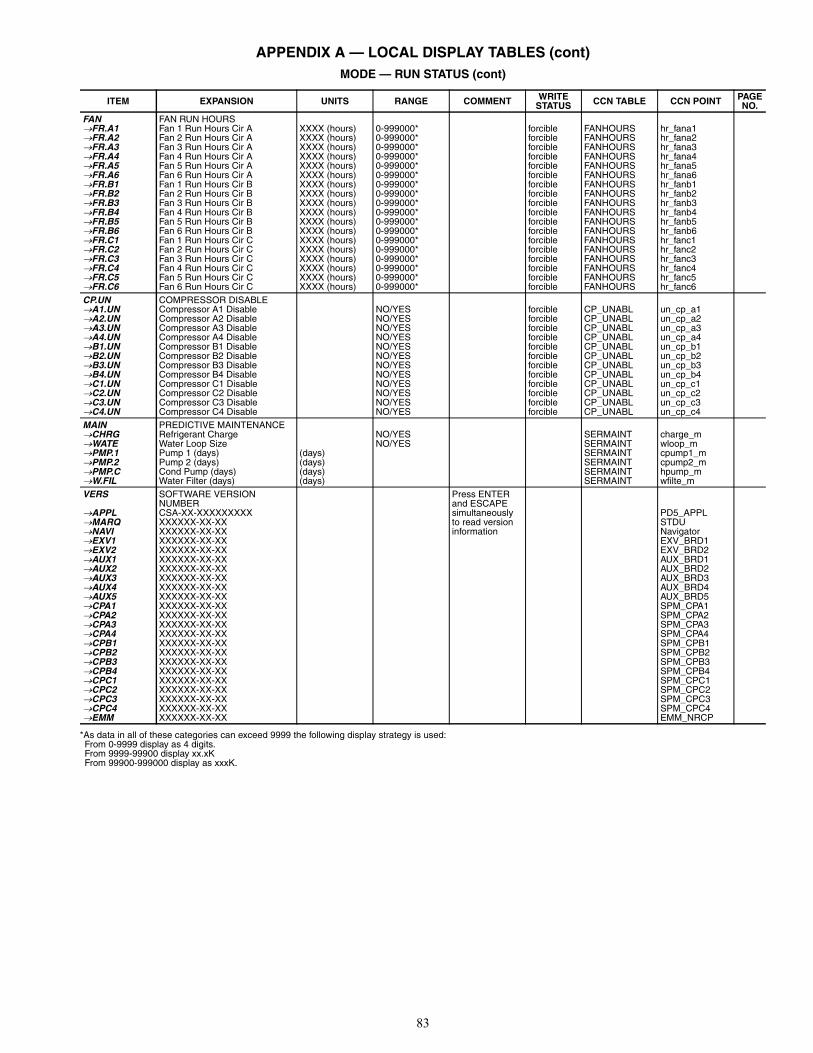
83
APPENDIX A — LOCAL DISPLAY TABLES (cont)MODE — RUN STATUS (cont)
*As data in all of these categories can exceed 9999 the following display strategy is used:From 0-9999 display as 4 digits.From 9999-99900 display xx.xKFrom 99900-999000 display as xxxK.
ITEM EXPANSION UNITS RANGE COMMENT WRITESTATUS CCN TABLE CCN POINT PAGE
NO.FAN FAN RUN HOURSFR.A1 Fan 1 Run Hours Cir A XXXX (hours) 0-999000* forcible FANHOURS hr_fana1FR.A2 Fan 2 Run Hours Cir A XXXX (hours) 0-999000* forcible FANHOURS hr_fana2FR.A3 Fan 3 Run Hours Cir A XXXX (hours) 0-999000* forcible FANHOURS hr_fana3FR.A4 Fan 4 Run Hours Cir A XXXX (hours) 0-999000* forcible FANHOURS hr_fana4FR.A5 Fan 5 Run Hours Cir A XXXX (hours) 0-999000* forcible FANHOURS hr_fana5FR.A6 Fan 6 Run Hours Cir A XXXX (hours) 0-999000* forcible FANHOURS hr_fana6FR.B1 Fan 1 Run Hours Cir B XXXX (hours) 0-999000* forcible FANHOURS hr_fanb1FR.B2 Fan 2 Run Hours Cir B XXXX (hours) 0-999000* forcible FANHOURS hr_fanb2FR.B3 Fan 3 Run Hours Cir B XXXX (hours) 0-999000* forcible FANHOURS hr_fanb3FR.B4 Fan 4 Run Hours Cir B XXXX (hours) 0-999000* forcible FANHOURS hr_fanb4FR.B5 Fan 5 Run Hours Cir B XXXX (hours) 0-999000* forcible FANHOURS hr_fanb5FR.B6 Fan 6 Run Hours Cir B XXXX (hours) 0-999000* forcible FANHOURS hr_fanb6FR.C1 Fan 1 Run Hours Cir C XXXX (hours) 0-999000* forcible FANHOURS hr_fanc1FR.C2 Fan 2 Run Hours Cir C XXXX (hours) 0-999000* forcible FANHOURS hr_fanc2FR.C3 Fan 3 Run Hours Cir C XXXX (hours) 0-999000* forcible FANHOURS hr_fanc3FR.C4 Fan 4 Run Hours Cir C XXXX (hours) 0-999000* forcible FANHOURS hr_fanc4FR.C5 Fan 5 Run Hours Cir C XXXX (hours) 0-999000* forcible FANHOURS hr_fanc5FR.C6 Fan 6 Run Hours Cir C XXXX (hours) 0-999000* forcible FANHOURS hr_fanc6CP.UN COMPRESSOR DISABLEA1.UN Compressor A1 Disable NO/YES forcible CP_UNABL un_cp_a1A2.UN Compressor A2 Disable NO/YES forcible CP_UNABL un_cp_a2A3.UN Compressor A3 Disable NO/YES forcible CP_UNABL un_cp_a3A4.UN Compressor A4 Disable NO/YES forcible CP_UNABL un_cp_a4B1.UN Compressor B1 Disable NO/YES forcible CP_UNABL un_cp_b1B2.UN Compressor B2 Disable NO/YES forcible CP_UNABL un_cp_b2B3.UN Compressor B3 Disable NO/YES forcible CP_UNABL un_cp_b3B4.UN Compressor B4 Disable NO/YES forcible CP_UNABL un_cp_b4C1.UN Compressor C1 Disable NO/YES forcible CP_UNABL un_cp_c1C2.UN Compressor C2 Disable NO/YES forcible CP_UNABL un_cp_c2C3.UN Compressor C3 Disable NO/YES forcible CP_UNABL un_cp_c3C4.UN Compressor C4 Disable NO/YES forcible CP_UNABL un_cp_c4MAIN PREDICTIVE MAINTENANCECHRG Refrigerant Charge NO/YES SERMAINT charge_mWATE Water Loop Size NO/YES SERMAINT wloop_mPMP.1 Pump 1 (days) (days) SERMAINT cpump1_mPMP.2 Pump 2 (days) (days) SERMAINT cpump2_mPMP.C Cond Pump (days) (days) SERMAINT hpump_mW.FIL Water Filter (days) (days) SERMAINT wfilte_mVERS SOFTWARE VERSION
NUMBERPress ENTER and ESCAPEsimultaneouslyto read versioninformation
APPL CSA-XX-XXXXXXXXX PD5_APPLMARQ XXXXXX-XX-XX STDUNAVI XXXXXX-XX-XX NavigatorEXV1 XXXXXX-XX-XX EXV_BRD1EXV2 XXXXXX-XX-XX EXV_BRD2AUX1 XXXXXX-XX-XX AUX_BRD1AUX2 XXXXXX-XX-XX AUX_BRD2AUX3 XXXXXX-XX-XX AUX_BRD3AUX4 XXXXXX-XX-XX AUX_BRD4AUX5 XXXXXX-XX-XX AUX_BRD5CPA1 XXXXXX-XX-XX SPM_CPA1CPA2 XXXXXX-XX-XX SPM_CPA2CPA3 XXXXXX-XX-XX SPM_CPA3CPA4 XXXXXX-XX-XX SPM_CPA4CPB1 XXXXXX-XX-XX SPM_CPB1CPB2 XXXXXX-XX-XX SPM_CPB2CPB3 XXXXXX-XX-XX SPM_CPB3CPB4 XXXXXX-XX-XX SPM_CPB4CPC1 XXXXXX-XX-XX SPM_CPC1CPC2 XXXXXX-XX-XX SPM_CPC2CPC3 XXXXXX-XX-XX SPM_CPC3CPC4 XXXXXX-XX-XX SPM_CPC4EMM XXXXXX-XX-XX EMM_NRCP
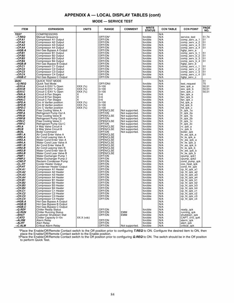
84
APPENDIX A — LOCAL DISPLAY TABLES (cont)MODE — SERVICE TEST
*Place the Enable/Off/Remote Contact switch to the Off position prior to configuring T.REQ to ON. Configure the desired item to ON, thenplace the Enable/Off/Remote Contact switch to the Enable position.
†Place the Enable/Off/Remote Contact switch to the Off position prior to configuring Q.REQ to ON. The switch should be in the Off positionto perform Quick Test.
ITEM EXPANSION UNITS RANGE COMMENT WRITESTATUS CCN TABLE CCN POINT PAGE
NO.TEST COMPRESSORS N/AT.REQ Manual Sequence OFF/ON* forcible N/A service_test 51,74CP.A1 Compressor A1 Output OFF/ON forcible N/A comp_serv_a_1 51CP.A2 Compressor A2 Output OFF/ON forcible N/A comp_serv_a_2 51CP.A3 Compressor A3 Output OFF/ON forcible N/A comp_serv_a_3 51CP.A4 Compressor A4 Output OFF/ON forcible N/A comp_serv_a_4 51HGB.A Hot Gas Bypass A Output OFF/ON forcible N/A hgbp_serv_aCP.B1 Compressor B1 Output OFF/ON forcible N/A comp_serv_b_1 51CP.B2 Compressor B2 Output OFF/ON forcible N/A comp_serv_b_2 51CP.B3 Compressor B3 Output OFF/ON forcible N/A comp_serv_b_3 51CP.B4 Compressor B4 Output OFF/ON forcible N/A comp_serv_b_4 51HGB.B Hot Gas Bypass B Output OFF/ON forcible N/A hgbp_serv_bCP.C1 Compressor C1 Output OFF/ON forcible N/A comp_serv_c_1 51CP.C2 Compressor C2 Output OFF/ON forcible N/A comp_serv_c_2 51CP.C3 Compressor C3 Output OFF/ON forcible N/A comp_serv_c_3 51CP.C4 Compressor C4 Output OFF/ON forcible N/A comp_serv_c_4 51HGB.C Hot Gas Bypass C Output OFF/ON forcible N/A hgbp_serv_cQUIC QUICK TEST MODE N/A 51Q.REQ Quick Test Mode OFF/ON† forcible N/A test_request 75EXV.A Circuit A EXV % Open XXX (%) 0-100 forcible N/A exv_qck_a 50,51EXV.B Circuit B EXV % Open XXX (%) 0-100 forcible N/A exv_qck_b 50,51EXV.C Circuit C EXV % Open XXX (%) 0-100 forcible N/A exv_qck_c 50,51FAN.A Circuit A Fan Stages X 0-6 forcible N/A fan_qck_aFAN.B Circuit B Fan Stages X 0-6 forcible N/A fan_qck_bFAN.C Circuit C Fan Stages X 0-6 forcible N/A fan_qck_cSPD.A Circ A Varifan position XXX (%) 0-100 forcible N/A hd_qck_aSPD.B Circ B Varifan position XXX (%) 0-100 forcible N/A hd_qck_bSPD.C Circ C Varifan position XXX (%) 0-100 forcible N/A hd_qck_cFRV.A Free Cooling Valve A OPEN/CLSE Not supported. forcible N/A fr_qck_1aFRP.A Refrigerant Pump Out A OFF/ON Not supported. forcible N/A fr_qck_2aFRV.B Free Cooling Valve B OPEN/CLSE Not supported. forcible N/A fr_qck_1bFRP.B Refrigerant Pump Out B OFF/ON Not supported. forcible N/A fr_qck_2bFRV.C Free Cooling Valve C OPEN/CLSE Not supported. forcible N/A fr_qck_1cFRP.C Refrigerant Pump Out C OFF/ON Not supported. forcible N/A fr_qck_2cRV.A 4 Way Valve Circuit A OPEN/CLSE Not supported. forcible N/A rv_qck_aRV.B 4 Way Valve Circuit B OPEN/CLSE Not supported. forcible N/A rv_qck_bBOIL Boiler Command OFF/ON Not supported. forcible N/A boiler_qckHR1.A Air Cond Enter Valve A OPEN/CLSE forcible N/A hr_ea_qck_aHR2.A Air Cond Leaving Valv A OPEN/CLSE forcible N/A hr_la_qck_aHR3.A Water Cond Enter Valv A OPEN/CLSE forcible N/A hr_ew_qck_aHR4.A Water Cond Leav Valve A OPEN/CLSE forcible N/A hr_lw_qck_aHR1.B Air Cond Enter Valve B OPEN/CLSE forcible N/A hr_ea_qck_bHR2.B Air Cond Leaving Valv B OPEN/CLSE forcible N/A hr_la_qck_bHR3.B Water Cond Enter Valv B OPEN/CLSE forcible N/A hr_ew_qck_bHR4.B Water Cond Leav Valve B OPEN/CLSE forcible N/A hr_lw_qck_bPMP.1 Water Exchanger Pump 1 OFF/ON forcible N/A cpump_qck1PMP.2 Water Exchanger Pump 2 OFF/ON forcible N/A cpump_qck2CND.P Reclaim Condenser Pump OFF/ON forcible N/A cond_pump_qckCL.HT Cooler Heater Output OFF/ON forcible N/A coo_heat_qckCP.HT Condenser Heater Output OFF/ON forcible N/A cond_htr_qckCH.A1 Compressor A1 Heater OFF/ON forcible N/A cp_ht_qck_a1CH.A2 Compressor A2 Heater OFF/ON forcible N/A cp_ht_qck_a2CH.A3 Compressor A3 Heater OFF/ON forcible N/A cp_ht_qck_a3CH.A4 Compressor A4 Heater OFF/ON forcible N/A cp_ht_qck_a4CH.B1 Compressor B1 Heater OFF/ON forcible N/A cp_ht_qck_b1CH.B2 Compressor B2 Heater OFF/ON forcible N/A cp_ht_qck_b2CH.B3 Compressor B3 Heater OFF/ON forcible N/A cp_ht_qck_b3CH.B4 Compressor B4 Heater OFF/ON forcible N/A cp_ht_qck_b4CH.C1 Compressor C1 Heater OFF/ON forcible N/A cp_ht_qck_c1CH.C2 Compressor C2 Heater OFF/ON forcible N/A cp_ht_qck_c2CH.C3 Compressor C3 Heater OFF/ON forcible N/A cp_ht_qck_c3CH.C4 Compressor C4 Heater OFF/ON forcible N/A cp_ht_qck_c4HGB.A Hot Gas Bypass A Output N/AHGB.B Hot Gas Bypass B Output N/AHGB.C Hot Gas Bypass C Output N/AQ.RDY Chiller Ready Status OFF/ON forcible N/A ready_qckQ.RUN Chiller Running Status OFF/ON EMM forcible N/A running_qckSHUT Customer Shutdown Stat OFF/ON EMM forcible N/A shutdown_qckCATO Chiller Capacity 0-10v XX.X (vdc) forcible N/A CAPT_010_qcKALRM Alarm Relay OFF/ON forcible N/A alarm_qckALRT Alert Relay OFF/ON forcible N/A alert_qckC.ALM Critical Alarm Relay OFF/ON Not supported. forcible N/A critical_qck
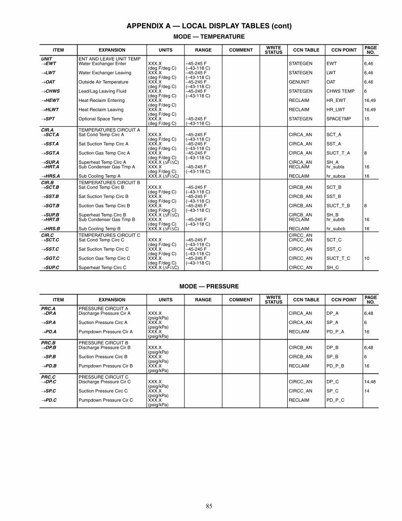
85
APPENDIX A — LOCAL DISPLAY TABLES (cont)MODE — TEMPERATURE
MODE — PRESSURE
ITEM EXPANSION UNITS RANGE COMMENT WRITESTATUS CCN TABLE CCN POINT PAGE
NO.UNIT ENT AND LEAVE UNIT TEMPEWT Water Exchanger Enter XXX.X
(deg F/deg C)–45-245 F(–43-118 C)
STATEGEN EWT 6,46
LWT Water Exchanger Leaving XXX.X(deg F/deg C)
–45-245 F(–43-118 C)
STATEGEN LWT 6,46
OAT Outside Air Temperature XXX.X(deg F/deg C)
–45-245 F(–43-118 C)
GENUNIT OAT 6,46
CHWS Lead/Lag Leaving Fluid XXX.X(deg F/deg C)
–45-245 F(–43-118 C)
STATEGEN CHWS TEMP 6
HEWT Heat Reclaim Entering XXX.X(deg F/deg C)
RECLAIM HR_EWT 16,49
HLWT Heat Reclaim Leaving XXX.X(deg F/deg C)
RECLAIM HR_LWT 16,49
SPT Optional Space Temp XXX.X(deg F/deg C)
–45-245 F(–43-118 C)
STATEGEN SPACETMP 15
CIR.A TEMPERATURES CIRCUIT ASCT.A Sat Cond Temp Circ A XXX.X
(deg F/deg C)–45-245 F(–43-118 C)
CIRCA_AN SCT_A
SST.A Sat Suction Temp Circ A XXX.X(deg F/deg C)
–45-245 F(–43-118 C)
CIRCA_AN SST_A
SGT.A Suction Gas Temp Circ A XXX.X(deg F/deg C)
–45-245 F(–43-118 C)
CIRCA_AN SUCT_T_A 8
SUP.A Superheat Temp Circ A XXX.X (F/C) CIRCA_AN SH_AHRT.A Sub Condenser Gas Tmp A XXX.X
(deg F/deg C)–45-245 F(–43-118 C)
RECLAIM hr_subta 16
HRS.A Sub Cooling Temp A XXX.X (F/C) RECLAIM hr_subca 16CIR.B TEMPERATURES CIRCUIT BSCT.B Sat Cond Temp Circ B XXX.X
(deg F/deg C)–45-245 F(–43-118 C)
CIRCB_AN SCT_B
SST.B Sat Suction Temp Circ B XXX.X(deg F/deg C)
–45-245 F(–43-118 C)
CIRCB_AN SST_B
SGT.B Suction Gas Temp Circ B XXX.X(deg F/deg C)
–45-245 F(–43-118 C)
CIRCB_AN SUCT_T_B 8
SUP.B Superheat Temp Circ B XXX.X (F/C) CIRCB_AN SH_BHRT.B Sub Condenser Gas Tmp B XXX.X
(deg F/deg C)–45-245 F(–43-118 C)
RECLAIM hr_subtb 16
HRS.B Sub Cooling Temp B XXX.X (F/C) RECLAIM hr_subcb 16CIR.C TEMPERATURES CIRCUIT C CIRCC_ANSCT.C Sat Cond Temp Circ C XXX.X
(deg F/deg C)–45-245 F(–43-118 C)
CIRCC_AN SCT_C
SST.C Sat Suction Temp Circ C XXX.X(deg F/deg C)
–45-245 F(–43-118 C)
CIRCC_AN SST_C
SGT.C Suction Gas Temp Circ C XXX.X(deg F/deg C)
–45-245 F(–43-118 C)
CIRCC_AN SUCT_T_C 10
SUP.C Superheat Temp Circ C XXX.X (F/C) CIRCC_AN SH_C
ITEM EXPANSION UNITS RANGE COMMENT WRITESTATUS CCN TABLE CCN POINT PAGE
NO.PRC.A PRESSURE CIRCUIT ADP.A Discharge Pressure Cir A XXX.X
(psig/kPa)CIRCA_AN DP_A 6,48
SP.A Suction Pressure Circ A XXX.X(psig/kPa)
CIRCA_AN SP_A 6
PD.A Pumpdown Pressure Cir A XXX.X(psig/kPa)
RECLAIM PD_P_A 16
PRC.B PRESSURE CIRCUIT BDP.B Discharge Pressure Cir B XXX.X
(psig/kPa)CIRCB_AN DP_B 6,48
SP.B Suction Pressure Circ B XXX.X(psig/kPa)
CIRCB_AN SP_B 6
PD.B Pumpdown Pressure Cir B XXX.X(psig/kPa)
RECLAIM PD_P_B 16
PRC.C PRESSURE CIRCUIT CDP.C Discharge Pressure Cir C XXX.X
(psig/kPa)CIRCC_AN DP_C 14,48
SP.C Suction Pressure Circ C XXX.X(psig/kPa)
CIRCC_AN SP_C 14
PD.C Pumpdown Pressure Cir C XXX.X(psig/kPa)
RECLAIM PD_P_C

86
APPENDIX A — LOCAL DISPLAY TABLES (cont)MODE — SET POINTS
MODE — INPUTS
ITEM EXPANSION UNITS RANGE COMMENT WRITESTATUS CCN TABLE CCN POINT PAGE
NO.COOL COOLING SETPOINTSCSP.1 Cooling Setpoint 1 XXXX.X
(deg F/deg C)–20-70 F(–29-21 C),Default = 44.0
forcible SETPOINT csp1 32,33,44
CSP.2 Cooing Setpoint 2 XXXX.X(deg F/deg C)
–20-70 F(–29-21 C),Default = 44.0
forcible SETPOINT csp2 32,33
CSP.3 Ice Setpoint XXXX.X(deg F/deg C)
–20-70 F(–29-21 C),Default = 44.0
forcible SETPOINT ice_sp 32,33,48
CRV1 Current No Reset Val XX.X (mA) 0-20,Default = 0
forcible SETPOINT v_cr_no 38
CRV2 Current Full Reset Val XX.X (mA) 0-20,Default = 0
forcible SETPOINT v_cr_fu 38
CRT1 Delta T No Reset Temp XXX.X (F/C) 0-125 F(0-69.4 C),Default = 0
forcible SETPOINT dt_cr_no 33
CRT2 Delta T Full Reset Temp XXX.X (F/C) 0-125 F(0-69.4 C),Default = 0
forcible SETPOINT dt_cr_fu 33
CRO1 OAT No Reset Temp XXX.X(deg F/deg C)
0-125 F(–18-52 C),Default = 14.0
forcible SETPOINT oatcr_no 34
CRO2 OAT Full Reset Temp XXX.X(deg F/deg C)
0-25 F(–18-52 C),Default = 14.0
forcible SETPOINT oatcr_fu 34
CRS1 Space T No Reset Temp XXX.X(deg F/deg C)
0-125 F(–18-52 C),Default = 14.0
forcible SETPOINT spacr_no 38
CRS2 Space T Full Reset Temp XXX.X(deg F/deg C)
0-125 F(–18-52 C),Default = 14.0
forcible SETPOINT spacr_fu 38
DGRC Degrees Cool Reset XX.X (F/C) –30-30 F(–16.7-16.7 C),Default = 0
forcible SETPOINT cr_deg 33,34,38
CAUT Cool Changeover Setpt XX.X(deg F/deg C)
Default = 75.0 Not supported. forcible SETPOINT cauto_sp
CRMP Cool Ramp Loading X.X 0.2-2.0 F(0.1-1.1 C),Default = 1.0
forcible cramp_sp 17,23,46
HEAT HEATING SETPOINTSHSP.1 Heating Setpoint 1 XXX.X
(deg F/deg C)Default = 100 Not supported. forcible SETPOINT HSP.1
HSP.2 Heating Setpoint 2 XXX.X(deg F/deg C)
Default = 100 Not supported. forcible SETPOINT HSP.2
HRV1 Current No Reset Val XX.X (mA) Default = 0 Not supported. forcible SETPOINT v_hr_noHRV2 Current Full Reset Val XX.X (mA) Default = 0 Not supported. forcible SETPOINT v_hr_fuHRT1 Delta T No Reset Temp XXX.X (F/C) Default = 0 Not supported. forcible SETPOINT dt_hr_noHRT2 Delta T Full Reset Temp XXX.X (F/C) Default = 0 Not supported. forcible SETPOINT dt_hr_fuHRO1 OAT No Reset Temp XXX.X
(deg F/deg C)Default = 14.0 Not supported. forcible SETPOINT oathr_no
HRO2 OAT Full Reset Temp XXX.X(deg F/deg C)
Default = 14.0 Not supported. forcible SETPOINT oathr_fu
DGRH Degrees Heat Reset XX.X (F/C) Default = 0 Not supported. forcible SETPOINT DGRHHAUT Heat Changeover Setpt XX.X
(deg F/deg C)Default = 64 Not supported. forcible SETPOINT hauto_sp
HRMP Heat Ramp Loading X.X Default = 1.0 Not supported. forcible SETPOINT hramp_spMISC MISCELLANEOUS SETPOINTSDLS1 Switch Limit Setpoint 1 XXX (%) 0-100,
Default = 100forcible SETPOINT lim_sp1 41
DLS2 Switch Limit Setpoint 2 XXX (%) 0-100,Default = 100
forcible SETPOINT lim_sp2 41
DLS3 Switch Limit Setpoint 3 XXX (%) 0-100,Default = 100
forcible SETPOINT lim_sp3
RSP Heat Reclaim Setpoint XXX.X(deg F/deg C)
Default = 122 forcible SETPOINT rsp 49
RDB Reclaim Deadband XX.X (F/C) Default = 9.0 forcible SETPOINT hr_deadb 49
ITEM EXPANSION UNITS RANGE COMMENT WRITESTATUS CCN TABLE CCN POINT PAGE
NO.GEN.I GENERAL INPUTSONOF On Off Switch OPEN/CLSE STATEGEN ONOF 6LOCK Cooler Interlock OPEN/CLSE STATEGEN LOCK_1 6,23DLS1 Demand Limit Switch 1 OPEN/CLSE STATEGEN LIM_SW1 6DLS2 Demand Limit Switch 2 OPEN/CLSE STATEGEN LIM_SW2 15ICE.D Ice Done OFF/ON STATEGEN ICE_SW 15,32DUAL Dual Setpoint Switch OFF/ON STATEGEN SETP_SW 6ELEC Electrical Box Safety OPEN/CLSE STATEGEN ELEC_BOX 6PUMP Pump Run Feedback OFF/ON STATEGEN PUMP_DEF 6OCCS Occupancy Override Swit OFF/ON STATEGEN OCC_OVSW 15RECL Heat Reclaim Switch OFF/ON STATEGEN RECL_SW 49HC.SW Heat Cool Switch Status OFF/ON STATEGEN HC_SWRLOC Remote Interlock Switch OPEN/CLSE STATEGEN REM-LOCK 15C.FLO Reclaim Cond Flow OPEN/CLSE STATEGEN CONDFLOW 16DMND 4-20 mA Demand Signal XXX.X (mA) 4 to 20 STATEGEN LIM_ANAL 15RSET 4-20 mA Reset/Setpoint XXX.X (mA) 4 to 20 STATEGEN SP_RESET 15

87
APPENDIX A — LOCAL DISPLAY TABLES (cont)MODE — OUTPUTS
ITEM EXPANSION UNITS RANGE COMMENT WRITESTATUS CCN TABLE CCN POINT PAGE
NO.CIR.A OUTPUTS CIRCUIT ACP.A1 Compressor A1 Relay OFF/ON CIRCA_D CP_A1 8CP.A2 Compressor A2 Relay OFF/ON CIRCA_D CP_A2 8CP.A3 Compressor A3 Relay OFF/ON CIRCA_D CP_A3 8CP.A4 Compressor A4 Relay OFF/ON CIRCA_D CP_A4 8HGB.A Hot Gas Bypass Circ A OFF/ON CIRCA_D HGBP_A 6HT.A1 Comp A1 Heater Relay OFF/ON CIRCA_D cp_a1_ht 8HT.A2 Comp A2 Heater Relay OFF/ON CIRCA_D cp_a2_ht 8HT.A3 Comp A3 Heater Relay OFF/ON CIRCA_D cp_a3_ht 8HT.A4 Comp A4 Heater Relay OFF/ON CIRCA_D cp_a4_ht 8FAN.A Circuit A Fan Stages X 0-6 CIRCA_D FAN_ST_ASPD.A Circ A Varifan Position XXX (%) 0-100 CIRCA_AN hd_pos_a 11EXV.A Circuit A EXV % Open XXX (%) 0-100 CIRCA_AN EXV_A 8FRP.A Refrigerant Pump Out A OFF/ON Not supported. CIRCA_D FR_PMP_AFRVA Free Cooling Valve A OPEN/CLSE Not supported. CIRCA_D FR_VLV_AHR1.A Air Cond Enter Valve A OPEN/CLSE RECLAIM hr_ca_a 16HR2.A Air Cond Leaving Valv A OPEN/CLSE RECLAIM hr_la_a 16HR3.A Water Cond Enter Valv A OPEN/CLSE RECLAIM hr_en_a 16HR4.A Water Cond Leav Valve A OPEN/CLSE RECLAIM hr_lw_a 16RV.A 4 Way Valve Circuit A OPEN/CLSE Not supported. CIRCA_D RV_ACIR.B OUTPUTS CIRCUIT BCP.B1 Compressor B1 Relay OFF/ON CIRCB_D CP_B1 8CP.B2 Compressor B2 Relay OFF/ON CIRCB_D CP_B2 8CP.B3 Compressor B3 Relay OFF/ON CIRCB_D CP_B3 8CP.B4 Compressor B4 Relay OFF/ON CIRCB_D CP_B4 8HGB.B Hot Gas Bypass Circ B OFF/ON CIRCB_D HGBP_B 6HT.B1 Comp B1 Heater Relay OFF/ON CIRCB_D CP_HT_B1 8HT.B2 Comp B2 Heater Relay OFF/ON CIRCB_D CP_HT_B2 8HT.B3 Comp B3 Heater Relay OFF/ON CIRCB_D CP_HT_B3 8HT.B4 Comp B4 Heater Relay OFF/ON CIRCB_D CP_HT_B4 8FAN.B Circuit B Fan Stages X 0-6 CIRCB_D FAN_ST_BSPD.B Circ B Varifan Position XXX (%) 0-100 CIRCB_AN hd_pos_b 11,12EXV.B Circuit B EXV % Open XXX (%) 0-100 CIRCB_AN EXV_B 8FRP.B Refrigerant Pump Out B OFF/ON Not supported. CIRCB_D FR_PMP_BFRVB Free Cooling Valve B OPEN/CLSE Not supported. CIRCA_D FR_VLV_BHR1.B Air Cond Enter Valve B OPEN/CLSE RECLAIM hr_ca_b 16HR2.B Air Cond Leaving Valv B OPEN/CLSE RECLAIM hr_la_b 16HR3.B Water Cond Enter Valv B OPEN/CLSE RECLAIM hr_en_b 16HR4.B Water Cond Leav Valve B OPEN/CLSE RECLAIM hr_lw_b 16RV.B 4 Way Valve Circuit B OPEN/CLSE Not supported. CIRCB_D RV_BCIR.C OUTPUTS CIRCUIT CCP.C1 Compressor C1 Relay OFF/ON CIRCC_D CP_C1 8CP.C2 Compressor C2 Relay OFF/ON CIRCC_D CP_C2 8CP.C3 Compressor C3 Relay OFF/ON CIRCC_D CP_C3 8CP.C4 Compressor C4 Relay OFF/ON CIRCC_D CP_C4 8HGB.C Hot Gas Bypass Circ C OFF/ON CIRCC_D HGBP_C 14HT.C1 Comp C1 Heater Relay OFF/ON CIRCC_D cp_c1_ht 8HT.C2 Comp C2 Heater Relay OFF/ON CIRCC_D cp_c2_ht 8HT.C3 Comp C3 Heater Relay OFF/ON CIRCC_D cp_c3_ht 8HT.C4 Comp C4 Heater Relay OFF/ON CIRCC_D cp_c4_ht 8FAN.C Circuit C Fan Stages X 0-6 CIRCC_D FAN_ST_CSPD.C Circ C Varifan Position XXX (%) 0-100 CIRCC_AN hd_pos_c 14EXV.C Circuit C EXV % Open XXX (%) 0-100 CIRCC_AN EXV_C 10FRP.C Refrigerant Pump Out C OFF/ON Not supported. CIRCC_D FR_PMP_ CFRVC Free Cooling Valve C OPEN/CLSE Not supported. CIRCC_D FR_VLV_CGEN.O GENERAL OUTPUTSPMP.1 Water Exchanger Pump 1 OFF/ON STATEGEN CPUMP_1 6PMP.2 Water Exchanger Pump 2 OFF/ON STATEGEN CPUMP_2 6CND.P Reclaim Condenser Pump OFF/ON STATEGEN COND_PUMP 16CO.HT Cooler Heater Output OFF/ON STATEGEN COOLHEAT 6CN.HT Condenser Heater Output OFF/ON RECLAIM cond_htr 16REDY Chiller Ready Status OFF/ON forcible RECLAIM READY 6RUN Chiller Running Status OFF/ON forcible STATEGEN RUNNING 15SHUT Customer Shutdown Stat OFF/ON forcible STATEGEN SHUTDOWN 15CATO Chiller Capacity 0-10 v XX.X forcible STATEGEN CAPT_010 15ALRM Alarm Relay OFF/ON STATEGEN ALARM 6ALRT Alert Relay OFF/ON STATEGEN ALERT 6BOIL Boiler Command OFF/ON Not supported. STATEGEN BOILERC.ALM Critical Alarm Relay OFF/ON forcible STATEGEN critical_qck

88
APPENDIX A — LOCAL DISPLAY TABLES (cont)MODE — CONFIGURATION
ITEM EXPANSION UNITS RANGE COMMENT WRITESTATUS DEFAULT CCN
TABLECCN
POINTPAGENO.
DISP DISPLAY CONFIGURATIONTEST Test Display LED’s OFF/ON OFF N/A display_testMETR Metric Display US/METR US DISPCONF DISPUNITLANG Language Selection 0=English
1=Espanol2=Francais3=Portugues4=Translated
0 DISPCONF LANGUAGE
UNIT UNIT CONFIGURATIONTYPE Unit Type 1=Air Cooled
2=Heat PumpHeat pump not supported
1 FACTORY unit_typ
TONS Unit Size XXX (tons) 56 to 300(nominal size — refer to Table 1 for unit modularcombinations)
FACTORY unitsize 66
VAR.A Nb Fan on Varifan Cir A X 0-6 0: No low ambient temperature head pressure control1:low ambient temperature head pressure control
FACTORY varfan_a
VAR.B Nb Fan on Varifan Cir B X 0-6 0: No low ambient temperature head pressure control1: low ambient temperature head pressure control
FACTORY varfan_b
VAR.C Nb Fan on Varifan Cir C X 0-6 0: No low ambient temperature head pressure control1: low ambient temperature head pressure control
FACTORY varfan_c
HGBP Hot Gas Bypass Control 0=Unused1=Startup Only2=Close Ctrl3=High Ambient
1 is default for med. temp. brine units (FLUD=2)
0 FACTORY hgbp_sel 17, 20-23
60HZ 60 Hz Frequency NO/YES YES FACTORY freq_60HRECL Heat Reclaim Select NO/YES NO FACTORY recl_opt 49EHS Electrical Heater Stage 0-4 Not supported 0 FACTORY ehs_selEMM EMM Module Installed NO/YES NO FACTORY emm_nrcp 65PAS.E Password Enable
Password Protection Must Be Disabled to Change Password
DSBL/ENBL ENBL FACTORY pass_enb
PASS Password XXX 1 to 0150 0111 FACTORY fac_passFREE Free Cooling Select NO/YES Not supported. NO FACTORY freecoolPD4.D Pro_Dialog User Display NO/YES Must be set to
NONO FACTORY pd4_disp
BOIL Boiler Command Select OFF/ON Not supported. OFF FACTORY boil_selVLT.S VLT Fan Drive Select NO/YES Not supported. NO FACTORY Vh_selRPM.F VLT Fan Drive RPM XXXX 0 to 1200 Not supported. 0 FACTORY Vh_rpmMCHX MCHX Exchanger Select NO/YES NO FACTORY mchx_selSERV SERVICE CONFIGURATIONFLUD Cooler Fluid Type 1=Water
2=Brine3=Low Brine
Low Brine is not supported.
1 SERVICE1 flui_typ 17,22-24 33,66,67,69
MOP EXV MOP Setpoint XX.X(deg F/deg C)
40-60 F(4.4-15.6 C)
50 SERVICE1 mop_sp 67
HP.TH High Pressure Threshold XXX.X (psi/kPa) 500-640 psi(3447 to4412 kPa)
609 SERVICE1 hp_th 23,48
SHP.A Cir A Superheat Setp XX.X (F/C) 3-14 F(1.7-7.8 C)
9.0 SERVICE1 sh_sp_a 67,69
SHP.B Cir B Superheat Setp XX.X (F/C) 3-14 F(1.7-7.8 C)
9.0 SERVICE1 sh_sp_b 67,69
SHP.C Cir C Superheat Setp XX.X (F/C) 3-14 F(1.7-7.8 C)
9.0 SERVICE1 sh_sp_c 67,69
HTR Cooler Heater DT Setp XX.X (F/C) 0.5-9 F(0.3-5.0 C)
2.0(Number of degrees added to brine freeze set point to enable cooler heater.)
SERVICE1 heatersp 51
EWTO Entering Water Control NO/YES NO SERVICE1 ewt_opt 33AU.SM Auto Start When SM Lost NO/YES NO SERVICE1 auto_sm 68BOTH HSM Both Command Select NO/YES NO USER both_selLLWT Brine Min. Fluid Temp. XX –20-38 F USER Mini_LwtLOSP Brine Freeze Setpoint XX.X
(deg F/deg C)–4-50 F(–20-10 C)
34.0 SERVICE1 lowestsp 23,24,33,51,66,69
HD.PG Varifan Proportion Gain XX.X –10-10 2.0 SERVICE1 hd_pgHD.DG Varifan Derivative Gain XX.X –10-10 0.4 SERVICE1 hd_dgHD.IG Varifan Integral Gain XX.X –10-10 0.2 SERVICE1 hd_igHR.MI Reclaim Water Valve Min XXX.X (%) 20 SERVICE1 min_3wHR.MA Reclaim Water Valve Max XXX.X (%) 100 SERVICE1 max_3wAVFA Attach Drive to Fan A NO/YES Not supported. NO SERVICE3 set_drvaAVFB Attach Drive to Fan B NO/YES Not supported. NO SERVICE3 set_drvbAVFC Attach Drive to Fan C NO/YES Not supported. NO SERVICE3 set_drvc
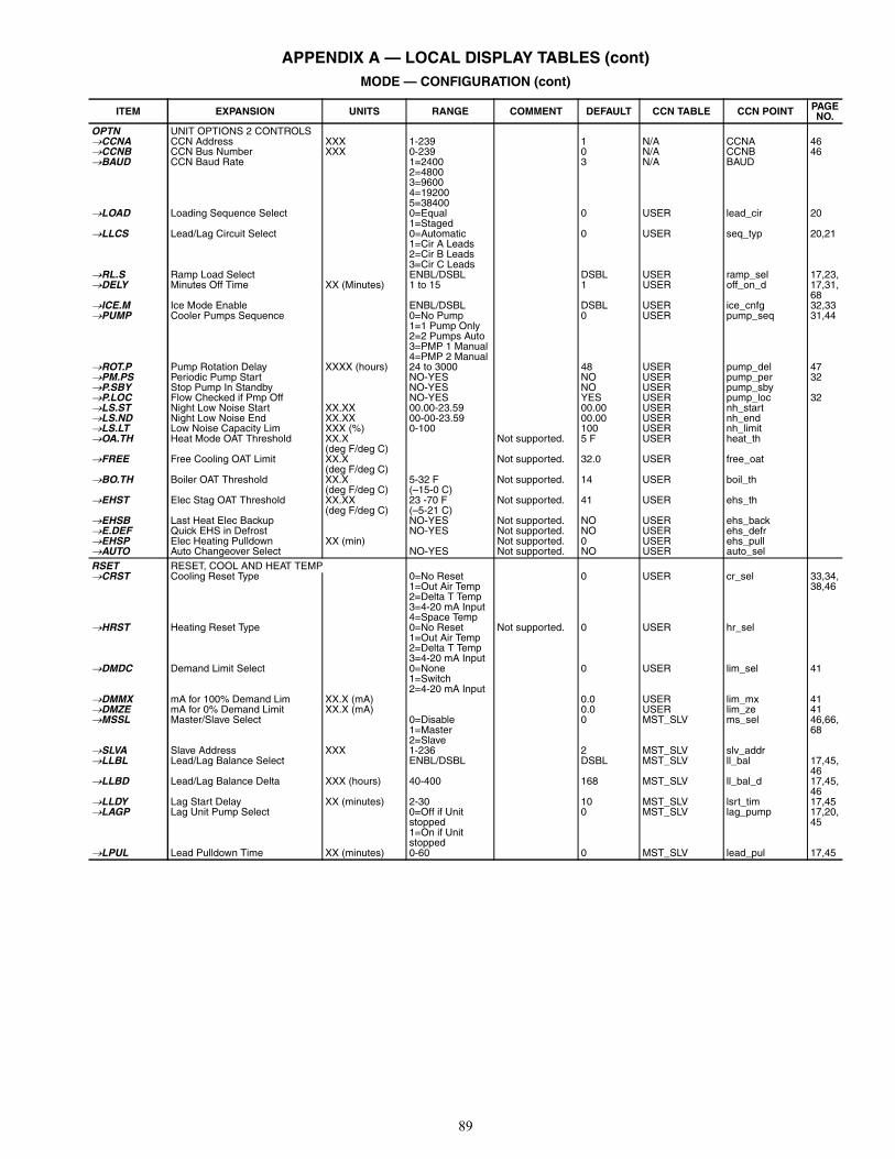
89
APPENDIX A — LOCAL DISPLAY TABLES (cont)MODE — CONFIGURATION (cont)
ITEM EXPANSION UNITS RANGE COMMENT DEFAULT CCN TABLE CCN POINT PAGENO.
OPTN UNIT OPTIONS 2 CONTROLSCCNA CCN Address XXX 1-239 1 N/A CCNA 46CCNB CCN Bus Number XXX 0-239 0 N/A CCNB 46BAUD CCN Baud Rate 1=2400
2=48003=96004=192005=38400
3 N/A BAUD
LOAD Loading Sequence Select 0=Equal1=Staged
0 USER lead_cir 20
LLCS Lead/Lag Circuit Select 0=Automatic1=Cir A Leads2=Cir B Leads3=Cir C Leads
0 USER seq_typ 20,21
RL.S Ramp Load Select ENBL/DSBL DSBL USER ramp_sel 17,23,DELY Minutes Off Time XX (Minutes) 1 to 15 1 USER off_on_d 17,31,
68ICE.M Ice Mode Enable ENBL/DSBL DSBL USER ice_cnfg 32,33PUMP Cooler Pumps Sequence 0=No Pump
1=1 Pump Only2=2 Pumps Auto3=PMP 1 Manual4=PMP 2 Manual
0 USER pump_seq 31,44
ROT.P Pump Rotation Delay XXXX (hours) 24 to 3000 48 USER pump_del 47PM.PS Periodic Pump Start NO-YES NO USER pump_per 32P.SBY Stop Pump In Standby NO-YES NO USER pump_sbyP.LOC Flow Checked if Pmp Off NO-YES YES USER pump_loc 32LS.ST Night Low Noise Start XX.XX 00.00-23.59 00.00 USER nh_startLS.ND Night Low Noise End XX.XX 00-00-23.59 00.00 USER nh_endLS.LT Low Noise Capacity Lim XXX (%) 0-100 100 USER nh_limitOA.TH Heat Mode OAT Threshold XX.X
(deg F/deg C)Not supported. 5 F USER heat_th
FREE Free Cooling OAT Limit XX.X(deg F/deg C)
Not supported. 32.0 USER free_oat
BO.TH Boiler OAT Threshold XX.X(deg F/deg C)
5-32 F (–15-0 C)
Not supported. 14 USER boil_th
EHST Elec Stag OAT Threshold XX.XX(deg F/deg C)
23 -70 F(–5-21 C)
Not supported. 41 USER ehs_th
EHSB Last Heat Elec Backup NO-YES Not supported. NO USER ehs_backE.DEF Quick EHS in Defrost NO-YES Not supported. NO USER ehs_defrEHSP Elec Heating Pulldown XX (min) Not supported. 0 USER ehs_pullAUTO Auto Changeover Select NO-YES Not supported. NO USER auto_selRSET RESET, COOL AND HEAT TEMPCRST Cooling Reset Type 0=No Reset
1=Out Air Temp2=Delta T Temp3=4-20 mA Input4=Space Temp
0 USER cr_sel 33,34,38,46
HRST Heating Reset Type 0=No Reset1=Out Air Temp2=Delta T Temp3=4-20 mA Input
Not supported. 0 USER hr_sel
DMDC Demand Limit Select 0=None1=Switch2=4-20 mA Input
0 USER lim_sel 41
DMMX mA for 100% Demand Lim XX.X (mA) 0.0 USER lim_mx 41DMZE mA for 0% Demand Limit XX.X (mA) 0.0 USER lim_ze 41MSSL Master/Slave Select 0=Disable
1=Master2=Slave
0 MST_SLV ms_sel 46,66,68
SLVA Slave Address XXX 1-236 2 MST_SLV slv_addrLLBL Lead/Lag Balance Select ENBL/DSBL DSBL MST_SLV ll_bal 17,45,
46LLBD Lead/Lag Balance Delta XXX (hours) 40-400 168 MST_SLV ll_bal_d 17,45,
46LLDY Lag Start Delay XX (minutes) 2-30 10 MST_SLV lsrt_tim 17,45LAGP Lag Unit Pump Select 0=Off if Unit
stopped1=On if Unit stopped
0 MST_SLV lag_pump 17,20,45
LPUL Lead Pulldown Time XX (minutes) 0-60 0 MST_SLV lead_pul 17,45
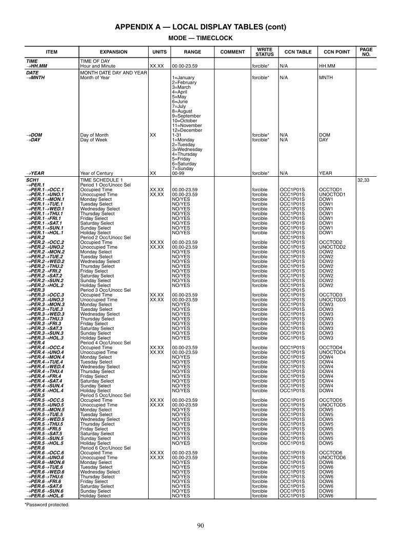
90
APPENDIX A — LOCAL DISPLAY TABLES (cont)MODE — TIMECLOCK
*Password protected.
ITEM EXPANSION UNITS RANGE COMMENT WRITESTATUS CCN TABLE CCN POINT PAGE
NO.TIME TIME OF DAYHH.MM Hour and Minute XX.XX 00.00-23.59 forcible* N/A HH.MMDATE MONTH DATE DAY AND YEARMNTH Month of Year 1=January
2=February3=March4=April5=May6=June7=July8=August9=September10=October11=November12=December
forcible* N/A MNTH
DOM Day of Month XX 1-31 forcible* N/A DOMDAY Day of Week 1=Monday
2=Tuesday3=Wednesday4=Thursday5=Friday6=Saturday7=Sunday
forcible* N/A DAY
YEAR Year of Century XX 00-99 forcible* N/A YEARSCH1 TIME SCHEDULE 1 32,33PER.1 Period 1 Occ/Unocc SelPER.1OCC.1 Occupied Time XX.XX 00.00-23.59 forcible OCC1P01S OCCTOD1PER.1UNO.1 Unoccupied Time XX.XX 00.00-23.59 forcible OCC1P01S UNOCTOD1PER.1MON.1 Monday Select NO/YES forcible OCC1P01S DOW1PER.1TUE.1 Tuesday Select NO/YES forcible OCC1P01S DOW1PER.1WED.1 Wednesday Select NO/YES forcible OCC1P01S DOW1PER.1THU.1 Thursday Select NO/YES forcible OCC1P01S DOW1PER.1FRI.1 Friday Select NO/YES forcible OCC1P01S DOW1PER.1SAT.1 Saturday Select NO/YES forcible OCC1P01S DOW1PER.1SUN.1 Sunday Select NO/YES forcible OCC1P01S DOW1PER.1HOL.1 Holiday Select NO/YES forcible OCC1P01S DOW1PER.2 Period 2 Occ/Unocc Sel OCC1P01SPER.2OCC.2 Occupied Time XX.XX 00.00-23.59 forcible OCC1P01S OCCTOD2PER.2UNO.2 Unoccupied Time XX.XX 00.00-23.59 forcible OCC1P01S UNOCTOD2PER.2MON.2 Monday Select NO/YES forcible OCC1P01S DOW2PER.2TUE.2 Tuesday Select NO/YES forcible OCC1P01S DOW2PER.2WED.2 Wednesday Select NO/YES forcible OCC1P01S DOW2PER.2THU.2 Thursday Select NO/YES forcible OCC1P01S DOW2PER.2FRI.2 Friday Select NO/YES forcible OCC1P01S DOW2PER.2SAT.2 Saturday Select NO/YES forcible OCC1P01S DOW2PER.2SUN.2 Sunday Select NO/YES forcible OCC1P01S DOW2PER.2HOL.2 Holiday Select NO/YES forcible OCC1P01S DOW2PER.3 Period 3 Occ/Unocc Sel OCC1P01SPER.3OCC.3 Occupied Time XX.XX 00.00-23.59 forcible OCC1P01S OCCTOD3PER.3UNO.3 Unoccupied Time XX.XX 00.00-23.59 forcible OCC1P01S UNOCTOD3PER.3MON.3 Monday Select NO/YES forcible OCC1P01S DOW3PER.3TUE.3 Tuesday Select NO/YES forcible OCC1P01S DOW3PER.3WED.3 Wednesday Select NO/YES forcible OCC1P01S DOW3PER.3THU.3 Thursday Select NO/YES forcible OCC1P01S DOW3PER.3FRI.3 Friday Select NO/YES forcible OCC1P01S DOW3PER.3SAT.3 Saturday Select NO/YES forcible OCC1P01S DOW3PER.3SUN.3 Sunday Select NO/YES forcible OCC1P01S DOW3PER.3HOL.3 Holiday Select NO/YES forcible OCC1P01S DOW3PER.4 Period 4 Occ/Unocc SelPER.4OCC.4 Occupied Time XX.XX 00.00-23.59 forcible OCC1P01S OCCTOD4PER.4UNO.4 Unoccupied Time XX.XX 00.00-23.59 forcible OCC1P01S UNOCTOD4PER.4MON.4 Monday Select NO/YES forcible OCC1P01S DOW4PER.4TUE.4 Tuesday Select NO/YES forcible OCC1P01S DOW4PER.4WED.4 Wednesday Select NO/YES forcible OCC1P01S DOW4PER.4THU.4 Thursday Select NO/YES forcible OCC1P01S DOW4PER.4FRI.4 Friday Select NO/YES forcible OCC1P01S DOW4PER.4SAT.4 Saturday Select NO/YES forcible OCC1P01S DOW4PER.4SUN.4 Sunday Select NO/YES forcible OCC1P01S DOW4PER.4HOL.4 Holiday Select NO/YES forcible OCC1P01S DOW4PER.5 Period 5 Occ/Unocc SelPER.5OCC.5 Occupied Time XX.XX 00.00-23.59 forcible OCC1P01S OCCTOD5PER.5UNO.5 Unoccupied Time XX.XX 00.00-23.59 forcible OCC1P01S UNOCTOD5PER.5MON.5 Monday Select NO/YES forcible OCC1P01S DOW5PER.5TUE.5 Tuesday Select NO/YES forcible OCC1P01S DOW5PER.5WED.5 Wednesday Select NO/YES forcible OCC1P01S DOW5PER.5THU.5 Thursday Select NO/YES forcible OCC1P01S DOW5PER.5FRI.5 Friday Select NO/YES forcible OCC1P01S DOW5PER.5SAT.5 Saturday Select NO/YES forcible OCC1P01S DOW5PER.5SUN.5 Sunday Select NO/YES forcible OCC1P01S DOW5PER.5HOL.5 Holiday Select NO/YES forcible OCC1P01S DOW5PER.6 Period 6 Occ/Unocc SelPER.6OCC.6 Occupied Time XX.XX 00.00-23.59 forcible OCC1P01S OCCTOD6PER.6UNO.6 Unoccupied Time XX.XX 00.00-23.59 forcible OCC1P01S UNOCTOD6PER.6MON.6 Monday Select NO/YES forcible OCC1P01S DOW6PER.6TUE.6 Tuesday Select NO/YES forcible OCC1P01S DOW6PER.6WED.6 Wednesday Select NO/YES forcible OCC1P01S DOW6PER.6THU.6 Thursday Select NO/YES forcible OCC1P01S DOW6PER.6FRI.6 Friday Select NO/YES forcible OCC1P01S DOW6PER.6SAT.6 Saturday Select NO/YES forcible OCC1P01S DOW6PER.6SUN.6 Sunday Select NO/YES forcible OCC1P01S DOW6PER.6HOL.6 Holiday Select NO/YES forcible OCC1P01S DOW6
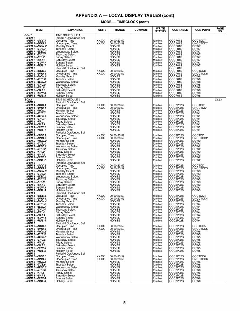
91
APPENDIX A — LOCAL DISPLAY TABLES (cont)MODE — TIMECLOCK (cont)
ITEM EXPANSION UNITS RANGE COMMENT WRITESTATUS CCN TABLE CCN POINT PAGE
NO.SCH1 TIME SCHEDULE 1PER.7 Period 7 Occ/Unocc SelPER.7OCC.7 Occupied Time XX.XX 00.00-23.59 forcible OCCP01S OCCTOD7PER.7UNO.7 Unoccupied Time XX.XX 00.00-23.59 forcible OCCP01S UNOCTOD7PER.7MON.7 Monday Select NO/YES forcible OCCP01S DOW7PER.7TUE.7 Tuesday Select NO/YES forcible OCCP01S DOW7PER.7WED.7 Wednesday Select NO/YES forcible OCCP01S DOW7PER.7THU.7 Thursday Select NO/YES forcible OCCP01S DOW7PER.7FRI.7 Friday Select NO/YES forcible OCCP01S DOW7PER.7SAT.7 Saturday Select NO/YES forcible OCCP01S DOW7PER.7SUN.7 Sunday Select NO/YES forcible OCCP01S DOW7PER.7HOL.7 Holiday Select NO/YES forcible OCCP01S DOW7PER.8 Period 8 Occ/Unocc Sel OCCP01SPER.8OCC.8 Occupied Time XX.XX 00.00-23.59 forcible OCCP01S OCCTOD8PER.8UNO.8 Unoccupied Time XX.XX 00.00-23.59 forcible OCCP01S UNOCTOD8PER.8MON.8 Monday Select NO/YES forcible OCCP01S DOW8PER.8TUE.8 Tuesday Select NO/YES forcible OCCP01S DOW8PER.8WED.8 Wednesday Select NO/YES forcible OCCP01S DOW8PER.8THU.8 Thursday Select NO/YES forcible OCCP01S DOW8PER.8FRI.8 Friday Select NO/YES forcible OCCP01S DOW8PER.8SAT.8 Saturday Select NO/YES forcible OCCP01S DOW8PER.8SUN.8 Sunday Select NO/YES forcible OCCP01S DOW8PER.8HOL.8 Holiday Select NO/YES forcible OCCP01S DOW8SCH2 TIME SCHEDULE 2 32,33PER.1 Period 1 Occ/Unocc SelPER.1OCC.1 Occupied Time XX.XX 00.00-23.59 forcible OCC2P02S OCCTOD1PER.1UNO.1 Unoccupied Time XX.XX 00.00-23.59 forcible OCC2P02S UNOCTOD1PER.1MON.1 Monday Select NO/YES forcible OCC2P02S DOW1PER.1TUE.1 Tuesday Select NO/YES forcible OCC2P02S DOW1PER.1WED.1 Wednesday Select NO/YES forcible OCC2P02S DOW1PER.1THU.1 Thursday Select NO/YES forcible OCC2P02S DOW1PER.1FRI.1 Friday Select NO/YES forcible OCC2P02S DOW1PER.1SAT.1 Saturday Select NO/YES forcible OCC2P02S DOW1PER.1SUN.1 Sunday Select NO/YES forcible OCC2P02S DOW1PER.1HOL.1 Holiday Select NO/YES forcible OCC2P02S DOW1PER.2 Period 2 Occ/Unocc SelPER.2OCC.2 Occupied Time XX.XX 00.00-23.59 forcible OCC2P02S OCCTODPER.2UNO.2 Unoccupied Time XX.XX 00.00-23.59 forcible OCC2P02S UNOCTOD2PER.2MON.2 Monday Select NO/YES forcible OCC2P02S DOW2PER.2TUE.2 Tuesday Select NO/YES forcible OCC2P02S DOW2PER.2WED.2 Wednesday Select NO/YES forcible OCC2P02S DOW2PER.2THU.2 Thursday Select NO/YES forcible OCC2P02S DOW2PER.2FRI.2 Friday Select NO/YES forcible OCC2P02S DOW2PER.2SAT.2 Saturday Select NO/YES forcible OCC2P02S DOW2PER.2SUN.2 Sunday Select NO/YES forcible OCC2P02S DOW2PER.2HOL.2 Holiday Select NO/YES forcible OCC2P02S DOW2PER.3 Period 3 Occ/Unocc SelPER.3OCC.3 Occupied Time XX.XX 00.00-23.59 forcible OCC2P02S OCCTODPER.3UNO.3 Unoccupied Time XX.XX 00.00-23.59 forcible OCC2P02S UNOCTOD3PER.3MON.3 Monday Select NO/YES forcible OCC2P02S DOW3PER.3TUE.3 Tuesday Select NO/YES forcible OCC2P02S DOW3PER.3WED.3 Wednesday Select NO/YES forcible OCC2P02S DOW3PER.3THU.3 Thursday Select NO/YES forcible OCC2P02S DOW3PER.3FRI.3 Friday Select NO/YES forcible OCC2P02S DOW3PER.3SAT.3 Saturday Select NO/YES forcible OCC2P02S DOW3PER.3SUN.3 Sunday Select NO/YES forcible OCC2P02S DOW3PER.3HOL.3 Holiday Select NO/YES forcible OCC2P02S DOW3PER.4 Period 4 Occ/Unocc SelPER.4OCC.4 Occupied Time XX.XX 00.00-23.59 forcible OCC2P02S OCCTOD4PER.4UNO.4 Unoccupied Time XX.XX 00.00-23.59 forcible OCC2P02S UNOCTOD4PER.4MON.4 Monday Select NO/YES forcible OCC2P02S DOW4PER.4TUE.4 Tuesday Select NO/YES forcible OCC2P02S DOW4PER.4WED.4 Wednesday Select NO/YES forcible OCC2P02S DOW4PER.4THU.4 Thursday Select NO/YES forcible OCC2P02S DOW4PER.4FRI.4 Friday Select NO/YES forcible OCC2P02S DOW4PER.4SAT.4 Saturday Select NO/YES forcible OCC2P02S DOW4PER.4SUN.4 Sunday Select NO/YES forcible OCC2P02S DOW4PER.4HOL.4 Holiday Select NO/YES forcible OCC2P02S DOW4PER.5 Period 5 Occ/Unocc SelPER.5OCC.5 Occupied Time XX.XX 00.00-23.59 forcible OCC2P02S OCCTOD5PER.5UNO.5 Unoccupied Time XX.XX 00.00-23.59 forcible OCC2P02S UNOCTOD5PER.5MON.5 Monday Select NO/YES forcible OCC2P02S DOW5PER.5TUE.5 Tuesday Select NO/YES forcible OCC2P02S DOW5PER.5WED.5 Wednesday Select NO/YES forcible OCC2P02S DOW5PER.5THU.5 Thursday Select NO/YES forcible OCC2P02S DOW5PER.5FRI.5 Friday Select NO/YES forcible OCC2P02S DOW5PER.5SAT.5 Saturday Select NO/YES forcible OCC2P02S DOW5PER.5SUN.5 Sunday Select NO/YES forcible OCC2P02S DOW5PER.5HOL.5 Holiday Select NO/YES forcible OCC2P02S DOW5PER.6 Period 6 Occ/Unocc SelPER.6OCC.6 Occupied Time XX.XX 00.00-23.59 forcible OCC2P02S OCCTOD6PER.6UNO.6 Unoccupied Time XX.XX 00.00-23.59 forcible OCC2P02S UNOCTOD6PER.6MON.6 Monday Select NO/YES forcible OCC2P02S DOW6PER.6TUE.6 Tuesday Select NO/YES forcible OCC2P02S DOW6PER.6WED.6 Wednesday Select NO/YES forcible OCC2P02S DOW6PER.6THU.6 Thursday Select NO/YES forcible OCC2P02S DOW6PER.6FRI.6 Friday Select NO/YES forcible OCC2P02S DOW6PER.6SAT.6 Saturday Select NO/YES forcible OCC2P02S DOW6PER.6SUN.6 Sunday Select NO/YES forcible OCC2P02S DOW6PER.6HOL.6 Holiday Select NO/YES forcible OCC2P02S DOW6
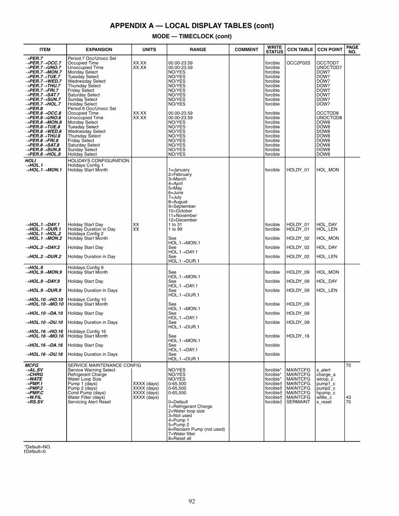
92
APPENDIX A — LOCAL DISPLAY TABLES (cont)MODE — TIMECLOCK (cont)
*Default=NO.†Default=0.
ITEM EXPANSION UNITS RANGE COMMENT WRITESTATUS CCN TABLE CCN POINT PAGE
NO.PER.7 Period 7 Occ/Unocc SelPER.7OCC.7 Occupied Time XX.XX 00.00-23.59 forcible OCC2P02S OCCTOD7PER.7UNO.7 Unoccupied Time XX.XX 00.00-23.59 forcible UNOCTOD7PER.7MON.7 Monday Select NO/YES forcible DOW7PER.7TUE.7 Tuesday Select NO/YES forcible DOW7PER.7WED.7 Wednesday Select NO/YES forcible DOW7PER.7THU.7 Thursday Select NO/YES forcible DOW7PER.7FRI.7 Friday Select NO/YES forcible DOW7PER.7SAT.7 Saturday Select NO/YES forcible DOW7PER.7SUN.7 Sunday Select NO/YES forcible DOW7PER.7HOL.7 Holiday Select NO/YES forcible DOW7PER.8 Period 8 Occ/Unocc SelPER.8OCC.8 Occupied Time XX.XX 00.00-23.59 forcible OCCTOD8PER.8UNO.8 Unoccupied Time XX.XX 00.00-23.59 forcible UNOCTOD8PER.8MON.8 Monday Select NO/YES forcible DOW8PER.8TUE.8 Tuesday Select NO/YES forcible DOW8PER.8WED.8 Wednesday Select NO/YES forcible DOW8PER.8THU.8 Thursday Select NO/YES forcible DOW8PER.8FRI.8 Friday Select NO/YES forcible DOW8PER.8SAT.8 Saturday Select NO/YES forcible DOW8PER.8SUN.8 Sunday Select NO/YES forcible DOW8PER.8HOL.8 Holiday Select NO/YES forcible DOW8HOLI HOLIDAYS CONFIGURATIONHOL.1 Holidays Config 1HOL.1MON.1 Holiday Start Month 1=January
2=February3=March4=April5=May6=June7=July8=August9=September10=October11=November12=December
forcible HOLDY_01 HOL_MON
HOL.1DAY.1 Holiday Start Day XX 1 to 31 forcible HOLDY_01 HOL_DAYHOL.1DUR.1 Holiday Duration in Day XX 1 to 99 forcible HOLDY_01 HOL_LENHOL.1HOL.2 Holidays Config 2HOL.1MON.2 Holiday Start Month See
HOL.1MON.1forcible HOLDY_02 HOL_MON
HOL.2DAY.2 Holiday Start Day SeeHOL.1DAY.1
forcible HOLDY_02 HOL_DAY
HOL.2DUR.2 Holiday Duration in Day SeeHOL.1DUR.1
forcible HOLDY_02 HOL_LEN
HOL.9 Holidays Config 9HOL.9MON.9 Holiday Start Month See
HOL.1MON.1forcible HOLDY_09 HOL_MON
HOL.9DAY.9 Holiday Start Day SeeHOL.1DAY.1
forcible HOLDY_09 HOL_DAY
HOL.9DUR.9 Holiday Duration in Days SeeHOL.1DUR.1
forcible HOLDY_09 HOL_LEN
HOL.10HO.10 Holidays Config 10HOL.10MO.10 Holiday Start Month See
HOL.1MON.1forcible HOLDY_09
HOL.10DA.10 Holiday Start Day SeeHOL.1DAY.1
forcible HOLDY_09
HOL.10DU.10 Holiday Duration in Days SeeHOL.1DUR.1
forcible HOLDY_09
HOL.16HO.16 Holidays Config 16HOL.16MO.16 Holiday Start Month See
HOL.1MON.1forcible HOLDY_16
HOL.16DA.16 Holiday Start Day SeeHOL.1DAY.1
forcible
HOL.16DU.16 Holiday Duration in Days SeeHOL.1DUR.1
forcible
MCFG SERVICE MAINTENANCE CONFIG 70AL.SV Service Warning Select NO/YES forcible* MAINTCFG s_alertCHRG Refrigerant Charge NO/YES forcible* MAINTCFG charge_aWATE Water Loop Size NO/YES forcible* MAINTCFG wloop_cPMP.1 Pump 1 (days) XXXX (days) 0-65,500 forcible† MAINTCFG pump1_cPMP.2 Pump 2 (days) XXXX (days) 0-65,500 forcible† MAINTCFG pump2_cPMP.C Cond Pump (days) XXXX (days) 0-65,500 forcible† MAINTCFG hpump_cW.FIL Water Filter (days) XXXX (days) forcible† MAINTCFG wfilte_c 43RS.SV Servicing Alert Reset 0=Default
1=Refrigerant Charge2=Water loop size3=Not used4=Pump 15=Pump 26=Reclaim Pump (not used)7=Water filter8=Reset all
forcible† SERMAINT s_reset 70
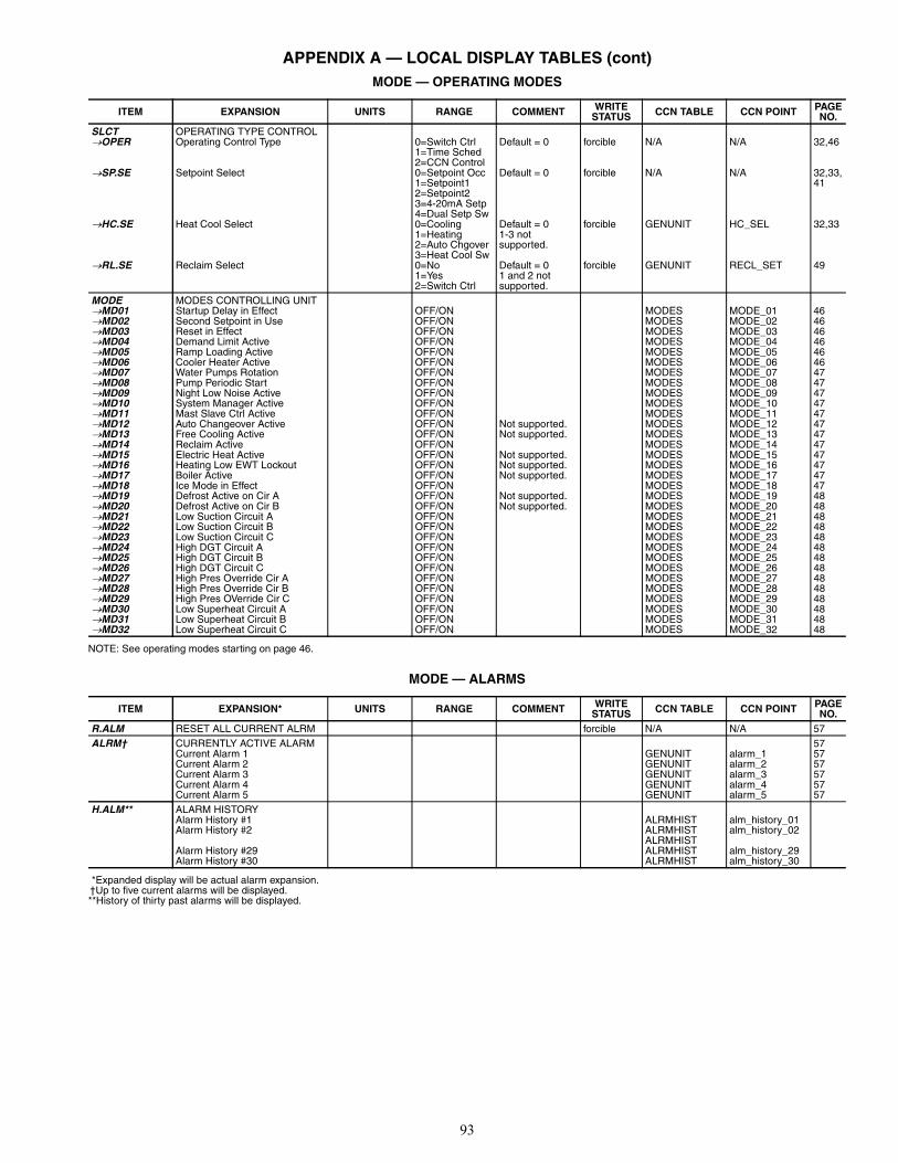
93
APPENDIX A — LOCAL DISPLAY TABLES (cont)MODE — OPERATING MODES
NOTE: See operating modes starting on page 46.
MODE — ALARMS
*Expanded display will be actual alarm expansion.†Up to five current alarms will be displayed.**History of thirty past alarms will be displayed.
ITEM EXPANSION UNITS RANGE COMMENT WRITESTATUS CCN TABLE CCN POINT PAGE
NO.SLCT OPERATING TYPE CONTROLOPER Operating Control Type 0=Switch Ctrl
1=Time Sched2=CCN Control
Default = 0 forcible N/A N/A 32,46
SP.SE Setpoint Select 0=Setpoint Occ1=Setpoint12=Setpoint23=4-20mA Setp4=Dual Setp Sw
Default = 0 forcible N/A N/A 32,33,41
HC.SE Heat Cool Select 0=Cooling1=Heating2=Auto Chgover3=Heat Cool Sw
Default = 01-3 notsupported.
forcible GENUNIT HC_SEL 32,33
RL.SE Reclaim Select 0=No1=Yes2=Switch Ctrl
Default = 01 and 2 notsupported.
forcible GENUNIT RECL_SET 49
MODE MODES CONTROLLING UNITMD01 Startup Delay in Effect OFF/ON MODES MODE_01 46MD02 Second Setpoint in Use OFF/ON MODES MODE_02 46MD03 Reset in Effect OFF/ON MODES MODE_03 46MD04 Demand Limit Active OFF/ON MODES MODE_04 46MD05 Ramp Loading Active OFF/ON MODES MODE_05 46MD06 Cooler Heater Active OFF/ON MODES MODE_06 46MD07 Water Pumps Rotation OFF/ON MODES MODE_07 47MD08 Pump Periodic Start OFF/ON MODES MODE_08 47MD09 Night Low Noise Active OFF/ON MODES MODE_09 47MD10 System Manager Active OFF/ON MODES MODE_10 47MD11 Mast Slave Ctrl Active OFF/ON MODES MODE_11 47MD12 Auto Changeover Active OFF/ON Not supported. MODES MODE_12 47MD13 Free Cooling Active OFF/ON Not supported. MODES MODE_13 47MD14 Reclaim Active OFF/ON MODES MODE_14 47MD15 Electric Heat Active OFF/ON Not supported. MODES MODE_15 47MD16 Heating Low EWT Lockout OFF/ON Not supported. MODES MODE_16 47MD17 Boiler Active OFF/ON Not supported. MODES MODE_17 47MD18 Ice Mode in Effect OFF/ON MODES MODE_18 47MD19 Defrost Active on Cir A OFF/ON Not supported. MODES MODE_19 48MD20 Defrost Active on Cir B OFF/ON Not supported. MODES MODE_20 48MD21 Low Suction Circuit A OFF/ON MODES MODE_21 48MD22 Low Suction Circuit B OFF/ON MODES MODE_22 48MD23 Low Suction Circuit C OFF/ON MODES MODE_23 48MD24 High DGT Circuit A OFF/ON MODES MODE_24 48MD25 High DGT Circuit B OFF/ON MODES MODE_25 48MD26 High DGT Circuit C OFF/ON MODES MODE_26 48MD27 High Pres Override Cir A OFF/ON MODES MODE_27 48MD28 High Pres Override Cir B OFF/ON MODES MODE_28 48MD29 High Pres OVerride Cir C OFF/ON MODES MODE_29 48MD30 Low Superheat Circuit A OFF/ON MODES MODE_30 48MD31 Low Superheat Circuit B OFF/ON MODES MODE_31 48MD32 Low Superheat Circuit C OFF/ON MODES MODE_32 48
ITEM EXPANSION* UNITS RANGE COMMENT WRITESTATUS CCN TABLE CCN POINT PAGE
NO.R.ALM RESET ALL CURRENT ALRM forcible N/A N/A 57ALRM† CURRENTLY ACTIVE ALARM 57
Current Alarm 1 GENUNIT alarm_1 57Current Alarm 2 GENUNIT alarm_2 57Current Alarm 3 GENUNIT alarm_3 57Current Alarm 4 GENUNIT alarm_4 57Current Alarm 5 GENUNIT alarm_5 57
H.ALM** ALARM HISTORYAlarm History #1 ALRMHIST alm_history_01Alarm History #2 ALRMHIST alm_history_02
ALRMHISTAlarm History #29 ALRMHIST alm_history_29Alarm History #30 ALRMHIST alm_history_30

94
APPENDIX B — CCN TABLESSTATUS DISPLAY TABLES
TABLE DISPLAY NAME RANGE UNITS POINT NAME WRITE STATUSCIRCA_AN
Percent Total Capacity 0 - 100 % CAPA_TDischarge Pressure nnn.n PSI DP_ASuction Pressure nnn.n PSI SP_ACrank Heater Current Cp1 nnn.n AMPS cpa1_curCrank Heater Current Cp2 nnn.n AMPS cpa2_curCrank Heater Current Cp3 nnn.n AMPS cpa3_curCrank Heater Current Cp4 nnn.n AMPS cpa4_curMotor Thermistor Comp 1 nnnn OHMS cpa1_tmpMotor Thermistor Comp 2 nnnn OHMS cpa2_tmpMotor Thermistor Comp 3 nnnn OHMS cpa3_tmpMotor Thermistor Comp 4 nnnn OHMS cpa4_tmpSaturated Condensing Tmp ±nnn.n °F SCT_ASaturated Suction Temp ±nnn.n °F SST_ASuction Gas Temperature ±nnn.n °F SUCT_T_ASuction Superheat Temp ±nnn.n ^F SH_AEXV Position 0 - 100 % EXV_AHead Press Actuator Pos 0 - 100 % hd_pos_a
CIRCA_DCompressor 1 Output On/Off CP_A1Compressor 2 Output On/Off CP_A2Compressor 3 Output On/Off CP_A3Compressor 4 Output On/Off CP_A4Compressor 1 Heater Out On/Off cp_a1_htCompressor 2 Heater Out On/Off cp_a2_htCompressor 3 Heater Out On/Off cp_a3_htCompressor 4 Heater Out On/Off cp_a4_htHot Gas Bypass Output On/Off HGBP_V_A
Fan Output DO # 1 On/Off fan_a1Fan Output DO # 2 On/Off fan_a2Fan Output DO # 3 On/Off fan_a3Fan Output DO # 4 On/Off fan_a4Fan Output DO # 5 On/Off fan_a5Fan Output DO # 6 On/Off fan_a6Fan Staging Number 0-6 FAN_ST_A
4 Way Refrigerant Valve On/Off RV_ACIRCB_AN
Percent Total Capacity 0 - 100 % CAPB_TDischarge Pressure nnn.n PSI DP_BSuction Pressure nnn.n PSI SP_BCrank Heater Current Cp1 nnn.n AMPS cpb1_curCrank Heater Current Cp2 nnn.n AMPS cpb2_curCrank Heater Current Cp3 nnn.n AMPS cpb3_curCrank Heater Current Cp4 nnn.n AMPS cpb4_curMotor Thermistor Comp 1 nnnn OHMS cpb1_tmpMotor Thermistor Comp 2 nnnn OHMS cpb2_tmpMotor Thermistor Comp 3 nnnn OHMS cpb3_tmpMotor Thermistor Comp 4 nnnn OHMS cpb4_tmpSaturated Condensing Tmp ±nnn.n °F SCT_BSaturated Suction Temp ±nnn.n °F SST_BSuction Gas Temperature ±nnn.n °F SUCT_T_BSuction Superheat Temp ±nnn.n ^F SH_BEXV Position 0-100 % EXV_BHead Press Actuator Pos 0-100 % hd_pos_b
CIRCB_DCompressor 1 Output On/Off CP_B1Compressor 2 Output On/Off CP_B2Compressor 3 Output On/Off CP_B3Compressor 4 Output On/Off CP_B4Compressor 1 Heater Out On/Off cp_b1_htCompressor 2 Heater Out On/Off cp_b2_htCompressor 3 Heater Out On/Off cp_b3_htCompressor 4 Heater Out On/Off cp_b4_htHot Gas Bypass Output On/Off HGBP_V_B
Fan Output DO # 1 On/Off fan_b1Fan Output DO # 2 On/Off fan_b2Fan Output DO # 3 On/Off fan_b3Fan Output DO # 4 On/Off fan_b4Fan Output DO # 5 On/Off fan_b5Fan Output DO # 6 On/Off fan_b6Fan Staging Number 0-6 FAN_ST_B
4 Way Refrigerant Valve On/Off RV_B
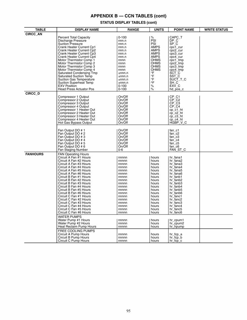
95
APPENDIX B — CCN TABLES (cont)STATUS DISPLAY TABLES (cont)
TABLE DISPLAY NAME RANGE UNITS POINT NAME WRITE STATUSCIRCC_AN
Percent Total Capacity 0-100 % CAPC_TDischarge Pressure nnn.n PSI DP_CSuction Pressure nnn.n PSI SP_CCrank Heater Current Cp1 nnn.n AMPS cpc1_curCrank Heater Current Cp2 nnn.n AMPS cpc2_curCrank Heater Current Cp3 nnn.n AMPS cpc3_curCrank Heater Current Cp4 nnn.n AMPS cpc4_curMotor Thermistor Comp 1 nnnn OHMS cpc1_tmpMotor Thermistor Comp 2 nnnn OHMS cpc2_tmpMotor Thermistor Comp 3 nnnn OHMS cpc3_tmpMotor Thermistor Comp 4 nnnn OHMS cpc4_tmpSaturated Condensing Tmp ±nnn.n °F SCT_CSaturated Suction Temp ±nnn.n °F SST_CSuction Gas Temperature ±nnn.n °F SUCT_T_CSuction Superheat Temp ±nnn.n ^F SH_CEXV Position 0-100 % EXV_CHead Press Actuator Pos 0-100 % hd_pos_c
CIRCC_DCompressor 1 Output On/Off CP_C1Compressor 2 Output On/Off CP_C2Compressor 3 Output On/Off CP_C3Compressor 4 Output On/Off CP_C4Compressor 1 Heater Out On/Off cp_c1_htCompressor 2 Heater Out On/Off cp_c2_htCompressor 3 Heater Out On/Off cp_c3_htCompressor 4 Heater Out On/Off cp_c4_htHot Gas Bypass Output On/Off HGBP_V_C
Fan Output DO # 1 On/Off fan_c1Fan Output DO # 2 On/Off fan_c2Fan Output DO # 3 On/Off fan_c3Fan Output DO # 4 On/Off fan_c4Fan Output DO # 5 On/Off fan_c5Fan Output DO # 6 On/Off fan_c6Fan Staging Number 0-6 FAN_ST_C
FANHOURS FAN Operating HoursCircuit A Fan #1 Hours nnnnn hours hr_fana1Circuit A Fan #2 Hours nnnnn hours hr_fana2Circuit A Fan #3 Hours nnnnn hours hr_fana3Circuit A Fan #4 Hours nnnnn hours hr_fana4Circuit A Fan #5 Hours nnnnn hours hr_fana5Circuit A Fan #6 Hours nnnnn hours hr_fana6Circuit B Fan #1 Hours nnnnn hours hr_fanb1Circuit B Fan #2 Hours nnnnn hours hr_fanb2Circuit B Fan #3 Hours nnnnn hours hr_fanb3Circuit B Fan #4 Hours nnnnn hours hr_fanb4Circuit B Fan #5 Hours nnnnn hours hr_fanb5Circuit B Fan #6 Hours nnnnn hours hr_fanb6Circuit C Fan #1 Hours nnnnn hours hr_fanc1Circuit C Fan #2 Hours nnnnn hours hr_fanc2Circuit C Fan #3 Hours nnnnn hours hr_fanc3Circuit C Fan #4 Hours nnnnn hours hr_fanc4Circuit C Fan #5 Hours nnnnn hours hr_fanc5Circuit C Fan #6 Hours nnnnn hours hr_fanc6WATER PUMPSWater Pump #1 Hours nnnnn hours hr_cpum1Water Pump #2 Hours nnnnn hours hr_cpum2Heat Reclaim Pump Hours nnnnn hours hr_hpumpFREE COOLING PUMPSCircuit A Pump Hours nnnnn hours hr_fcp_aCircuit B Pump Hours nnnnn hours hr_fcp_bCircuit C Pump Hours nnnnn hours hr_fcp_c

96
APPENDIX B — CCN TABLES (cont)STATUS DISPLAY TABLES (cont)
* Text reflects status of valve “Closed,” “Closing,” “Opened,” “Open-ing,” “Stopped,” or “Failed.”
TABLE DISPLAY NAME RANGE UNITS POINT NAME WRITE STATUSFREECOOL GENERAL PARAMETER
Free Cooling Disable? Yes/No FC_SWLWT-OAT Delta nnn.n ^F fc_deltaCurrent Cooling Power nnn KW cool_pwrEstimated FreeCool Power nnn KW fc_pwrNext session allowed in nn min fc_nextCooling/FreeCool Timeout nn min fc_tmoutFree Cool Conditions OK? Yes/No fc_readyFree Cool Request ? Yes/No fc_reqstValve Actuator Heaters ? On/Off FC_HTRCIRCUIT AFree Cooling Active Yes/No fc_on_aFan Staging Number 1-6 FAN_ST_A3 Way Valve Position nnn % fc_vlv_a3 Way Valve Status text* FC_VLV_ARefrigerant Pump Out On/Off fc_pmp_aPump Inlet Pressure nnn PSI fc_inp_aPump Outlet Pressure nnn PSI fc_oup_aPump Differential Pressure nnn PSI fc_dp_aCIRCUIT BFree Cooling Active Yes/No fc_on_bFan Staging Number 1-6 FAN_ST_B3 Way Valve Position nnn % fc_vlv_b3 Way Valve Status text* FC_VLV_BRefrigerant Pump Out On/Off fc_pmp_bPump Inlet Pressure nnn PSI fc_inp_bPump Outlet Pressure nnn PSI fc_oup_bPump Differential Pressure nnn PSI fc_dp_b

97
APPENDIX B — CCN TABLES (cont)STATUS DISPLAY TABLES (cont)
TABLE DISPLAY NAME RANGE UNITS POINT NAME WRITE STATUSGENUNIT GENERAL PARAMETER
Control Type LocalCCNRemote
ctr_type
Run Status 0 = Off1 = Running2 = Stopping3 = Delay4 = Tripout5 = Ready6 = Override7 = Defrost8 = Run Test9 = Test
STATUS
CCN Chiller Start/Stop Enable/Disable CHIL_S_S forcibleChiller Occupied? Yes/No CHIL_OCC forcibleMinutes Left for Start 0-15 min min_leftHeat/Cool Status 0 = Cool, 1 = Heat
2 = Stand-by3 = Both
HEATCOOL
Heat/Cool Select (0=Cool, 1=Heat,2= Auto)
0 = Cool1 = Heat2 = Auto
HC_SEL forcible
Heat Reclaim Select Yes/No RECL_SEL forcibleFree Cooling Disable Yes/No FC_DSBLEAlarm State 0 Normal
1 Partial2 Shutdown
ALM
Current Alarm 1 nnnnn alarm_1Current Alarm 2 nnnnn alarm_2Current Alarm 3 nnnnn alarm_3Current Alarm 4 nnnnn alarm_4Current Alarm 5 nnnnn alarm_5Percent Total Capacity nnn % CAP_TActive Demand Limit Val nnn % DEM_LIM forcibleLag Capacity Limit Value nnn % LAG_LIMCurrent Setpoint ±nnn.n °F SPSetpoint Occupied Yes/No SP_OCC forcibleSetpoint Control Setpt 1
Setpt 2Ice_sp4-20mAAuto
sp_ctrl
Control Point ±nnn.n °F CTRL_PNT forcibleControlled Water Temp ±nnn.n °F CTRL_WTExternal Temperature ±nnn.n °F OATEmergency Stop Enable/Disable EMSTOP forcible
MODES OPERATING MODESStartup Delay in Effect Yes/No Mode_01Second Setpoint in Use Yes/No Mode_02Reset in Effect Yes/No Mode_03Demand Limit Active Yes/No Mode_04Ramp Loading Active Yes/No Mode_05Cooler Heater Active Yes/No Mode_06Cooler Pumps Rotation Yes/No Mode_07Pump Periodic Start Yes/No Mode_08Night Low Noise Active Yes/No Mode_09System Manager Active Yes/No Mode_10Master Slave Active Yes/No Mode_11Auto Changeover Active Yes/No Mode_12Free Cooling Active Yes/No Mode_13Reclaim Active Yes/No Mode_14Electric Heat Active Yes/No Mode_15Heating Low EWT Lockout Yes/No Mode_16Boiler Active Yes/No Mode_17Ice Mode in Effect Yes/No Mode_18Defrost Active On Cir A Yes/No Mode_19Defrost Active On Cir B Yes/No Mode_20Low Suction Circuit A Yes/No Mode_21Low Suction Circuit B Yes/No Mode_22Low Suction Circuit C Yes/No Mode_23High DGT Circuit A Yes/No Mode_24High DGT Circuit B Yes/No Mode_25High DGT Circuit C Yes/No Mode_26High Pres Override Cir A Yes/No Mode_27High Pres Override Cir B Yes/No Mode_28High Pres Override Cir C Yes/No Mode_29Low Superheat Circuit A Yes/No Mode_30Low Superheat Circuit B Yes/No Mode_31Low Superheat Circuit C Yes/No Mode_32
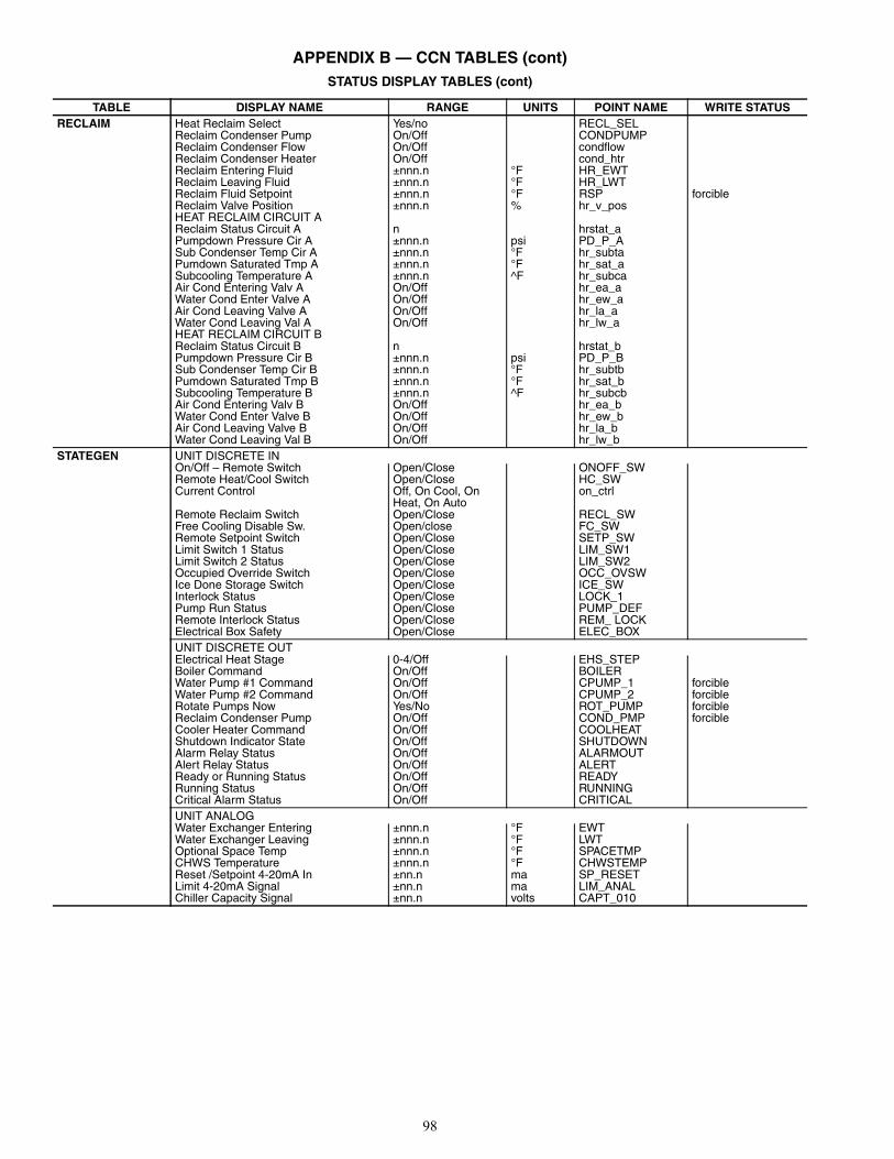
98
APPENDIX B — CCN TABLES (cont)STATUS DISPLAY TABLES (cont)
TABLE DISPLAY NAME RANGE UNITS POINT NAME WRITE STATUSRECLAIM Heat Reclaim Select Yes/no RECL_SEL
Reclaim Condenser Pump On/Off CONDPUMPReclaim Condenser Flow On/Off condflowReclaim Condenser Heater On/Off cond_htrReclaim Entering Fluid ±nnn.n °F HR_EWTReclaim Leaving Fluid ±nnn.n °F HR_LWTReclaim Fluid Setpoint ±nnn.n °F RSP forcibleReclaim Valve Position ±nnn.n % hr_v_posHEAT RECLAIM CIRCUIT AReclaim Status Circuit A n hrstat_aPumpdown Pressure Cir A ±nnn.n psi PD_P_ASub Condenser Temp Cir A ±nnn.n °F hr_subtaPumdown Saturated Tmp A ±nnn.n °F hr_sat_aSubcooling Temperature A ±nnn.n ^F hr_subcaAir Cond Entering Valv A On/Off hr_ea_aWater Cond Enter Valve A On/Off hr_ew_aAir Cond Leaving Valve A On/Off hr_la_aWater Cond Leaving Val A On/Off hr_lw_aHEAT RECLAIM CIRCUIT BReclaim Status Circuit B n hrstat_bPumpdown Pressure Cir B ±nnn.n psi PD_P_BSub Condenser Temp Cir B ±nnn.n °F hr_subtbPumdown Saturated Tmp B ±nnn.n °F hr_sat_bSubcooling Temperature B ±nnn.n ^F hr_subcbAir Cond Entering Valv B On/Off hr_ea_bWater Cond Enter Valve B On/Off hr_ew_bAir Cond Leaving Valve B On/Off hr_la_bWater Cond Leaving Val B On/Off hr_lw_b
STATEGEN UNIT DISCRETE INOn/Off – Remote Switch Open/Close ONOFF_SWRemote Heat/Cool Switch Open/Close HC_SWCurrent Control Off, On Cool, On
Heat, On Autoon_ctrl
Remote Reclaim Switch Open/Close RECL_SWFree Cooling Disable Sw. Open/close FC_SWRemote Setpoint Switch Open/Close SETP_SWLimit Switch 1 Status Open/Close LIM_SW1Limit Switch 2 Status Open/Close LIM_SW2Occupied Override Switch Open/Close OCC_OVSWIce Done Storage Switch Open/Close ICE_SWInterlock Status Open/Close LOCK_1Pump Run Status Open/Close PUMP_DEFRemote Interlock Status Open/Close REM_ LOCKElectrical Box Safety Open/Close ELEC_BOXUNIT DISCRETE OUTElectrical Heat Stage 0-4/Off EHS_STEPBoiler Command On/Off BOILERWater Pump #1 Command On/Off CPUMP_1 forcibleWater Pump #2 Command On/Off CPUMP_2 forcibleRotate Pumps Now Yes/No ROT_PUMP forcibleReclaim Condenser Pump On/Off COND_PMP forcibleCooler Heater Command On/Off COOLHEATShutdown Indicator State On/Off SHUTDOWNAlarm Relay Status On/Off ALARMOUTAlert Relay Status On/Off ALERTReady or Running Status On/Off READYRunning Status On/Off RUNNINGCritical Alarm Status On/Off CRITICALUNIT ANALOGWater Exchanger Entering ±nnn.n °F EWTWater Exchanger Leaving ±nnn.n °F LWTOptional Space Temp ±nnn.n °F SPACETMPCHWS Temperature ±nnn.n °F CHWSTEMPReset /Setpoint 4-20mA In ±nn.n ma SP_RESETLimit 4-20mA Signal ±nn.n ma LIM_ANALChiller Capacity Signal ±nn.n volts CAPT_010

99
APPENDIX B — CCN TABLES (cont)STATUS DISPLAY TABLES (cont)
CONFIGURATION DISPLAY TABLES
*Day of week where daylight savings time will occur in the morning(at 2:00 am). In the default setting, daylight savings time occurs onSunday (7) morning, 1 hour shall be added when entering and 1hour subtracted when leaving.
†Date once selected (from 1) shall occur in the week numberentered. 1: If day of week selected is 7 (Sunday) time change willoccur the first Sunday (week number 1) in the month. 5: If day ofweek selected is 7 (Sunday) time change will occur the lastSunday of the month (week number 4 or 5).
TABLE DISPLAY NAME RANGE UNITS POINT NAME WRITE STATUSSTRTHOUR Machine Operating Hours nnnnn hours HR_MACH
Machine Starts Number nnnnn st_machCompressor A1 Hours nnnnn hours HR_CP_A1Compressor A2 Hours nnnnn hours HR_CP_A2Compressor A3 Hours nnnnn hours HR_CP_A3Compressor A4 Hours nnnnn hours HR_CP_A4Compressor A1 Starts nnnnn st_cp_a1Compressor A2 Starts nnnnn st_cp_a2Compressor A3 Starts nnnnn st_cp_a3Compressor A4 Starts nnnnn st_cp_a4Compressor B1 Hours nnnnn hours HR_CP_B1Compressor B2 Hours nnnnn hours HR_CP_B2Compressor B3 Hours nnnnn hours HR_CP_B3Compressor B4 Hours nnnnn hours HR_CP_B4Compressor B1 Starts nnnnn st_cp_b1Compressor B2 Starts nnnnn st_cp_b2Compressor B3 Starts nnnnn st_cp_b3Compressor B4 Starts nnnnn st_cp_b4Compressor C1 Hours nnnnn hours HR_CP_C1Compressor C2 Hours nnnnn hours HR_CP_C2Compressor C3 Hours nnnnn hours HR_CP_C3Compressor C4 Hours nnnnn hours HR_CP_C4Compressor C1 Starts nnnnn st_cp_c1Compressor C2 Starts nnnnn st_cp_c2Compressor C4 Starts nnnnn st_cp_c3Compressor C4 Starts nnnnn st_cp_c4CYCLESStarts Max During 1 Hour nn st_cp_mx Starts/hr From Last 24 h nn st_cp_avCircuit A Defrost Number nnnnn nb_def_aCircuit B Defrost Number nnnnn nb_def_b
TABLE DISPLAY NAME RANGE DEFAULT UNITS POINT NAMEALARMDEF/ALARMS01
Alarm Routing Control 0 or 1 for each posi-tion
00000000 ALRM_CNT
Alarm Equipment Priority 0-7 4 EQP_TYPComm Failure Retry Time 1-240 10 min RETRY_TMRealarm Time 1-255 30 min RE_ALARMAlarm System Name 8 chars PRO_RBRQ ALRM_NAM
BRODEFS/BRODCASTS
Activate 0=Unused1=Broadcast time, date, holiday flag and OAT (as like existing pro_dialog control).2=For Standalone chiller. Daylight sav-ings time & holiday determination will be done without broadcasting through the bus.
2 — Ccnbroad
OAT Broadcast Bus # 0 to 239 0 Oatbusnm Element # 0 to 239 0 OatlocadDAYLIGHT SAVINGS SELECT Disable/Enable Disable dayl_selENTERINGMonth 1 to 12 3 StartmonDay of week* (1=Monday) 1 to 7 7 StartdowWeek Number of Month† 1 to 5 5 StartwomLEAVINGMonth 1 to 12 10 StopmonDay of week* (1=Monday) 1 to 7 7 StopdowWeek Number of Month† 1 to 5 5 stopwom
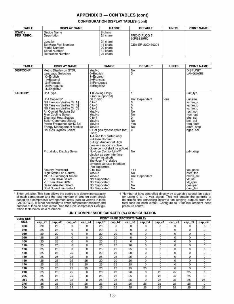
100
APPENDIX B — CCN TABLES (cont)CONFIGURATION DISPLAY TABLES (cont)
* Enter unit size. This item allows the controls to determine capacityof each compressor and the total number of fans on each circuitbased on a compressor arrangement array (can be viewed in tableFACTORY2). It is not necessary to enter compressor capacity andnumber of fans on each circuit. See the Unit Compressor Configu-ration table below as a reference.
† Number of fans controlled directly by a variable speed fan actua-tor using 0 to 10 vdc signal. This will enable the controls todetermine the remaining discrete fan staging outputs from thetotal fans on each circuit. Configure to 1 for low ambient headpressure control.
UNIT COMPRESSOR CAPACITY (%) CONFIGURATION
TABLE DISPLAY NAME RANGE DEFAULT UNITS POINT NAME!CtrlD / PD5_RBRQ:
Device Name 8 charsDescription 24 chars PRO-DIALOG 5
30RB&30RQLocation 24 charsSoftware Part Number 16 chars CSA-SR-20C460301Model Number 20 charsSerial Number 12 charsReference Number 24 chars
TABLE DISPLAY NAME RANGE DEFAULT UNITS POINT NAMEDISPCONF Metric Display on STDU Yes/No No DISPUNIT
Language Selection 0=English 1=Espanol 2=Francais 3=Portugues 4=English2
0=English1=Espanol2=Francais3=Portugues4=English2
0 LANGUAGE
FACTORY Unit Type 1 (Cooling Only),2 (not supported)
1 unit_typ
Unit Capacity* 56 to 500 Unit Dependent tons unitsizeNB Fans on Varifan Cir A† 0 to 6 0 varfan_aNB Fans on Varifan Cir B† 0 to 6 0 varfan_bNB Fans on Varifan Cir C† 0 to 6 0 varfan_cAir Cooled Reclaim Sel Yes/No No recl_optFree Cooling Select Yes/No No free_optElectrical Heat Stages 0 to 4 0 ehs_selBoiler Command Select Yes/No No boil_selPower Frequence 60HZ Sel Yes/No Yes freq_60HEnergy Management Module Yes/No No emm_nrcpHot Gas Bypass Select 0-Hot gas bypass valve (not
used)1=Used for Startup only2=Close Control3=High Ambient (if High pressure mode is active, close control shall be active)
0 hgbp_sel
Pro_dialog Display Selec No=Use ComfortLink™display as user interface (factory installed)Yes=Use Pro_dialogsynopsis as user interface (not supported)
No pd4_disp
Factory Password 0 to 150 111 fac_passHigh Static Fan Control Yes/No No hsta_fanMCHX Exchanger Select Yes/No Unit Dependent mchx_selVLT Fan Drive Select Not Supported 0 vlt_selVLT Fan Drive RPM Not Supported 0 vlt_rpmDesuperheater Select Not Supported No desuperDual Speed Fan Select Not Supported No dual_fan
30RB UNIT SIZE
POINT NAME (FACTORY2 TABLE)cap_a1 cap_a2 cap_a3 cap_a4 cap_b1 cap_b2 cap_b3 cap_b4 cap_c1 cap_c2 cap_c3 cap_c4
060 20 20 0 0 20 0 0 0 0 0 0 0070 25 25 0 0 20 0 0 0 0 0 0 0080 20 20 0 0 20 20 0 0 0 0 0 0090 25 25 0 0 20 20 0 0 0 0 0 0100 25 25 0 0 25 25 0 0 0 0 0 0110 25 25 0 0 20 20 20 0 0 0 0 0120 25 25 0 0 25 25 25 0 0 0 0 0130 25 25 25 0 20 20 20 0 0 0 0 0150 25 25 25 0 25 25 25 0 0 0 0 0160 25 25 25 25 20 20 20 0 0 0 0 0170 25 25 25 25 25 25 25 0 0 0 0 0190 25 25 25 25 25 25 25 25 0 0 0 0210 25 25 25 0 20 20 20 0 25 25 25 0225 25 25 25 0 25 25 25 0 25 25 25 0 250 25 25 25 0 25 25 25 0 25 25 25 25275 25 25 25 25 25 25 25 25 25 25 25 0300 25 25 25 25 25 25 25 25 25 25 25 25

101
APPENDIX B — CCN TABLES (cont)CONFIGURATION DISPLAY TABLES (cont)
NOTES:1. Compressor capacity will be automatically be determined if unit
size entered in FACTORY1 table matches the values in the unitcompressor configuration table.
2. Total number of fans includes fans controlled by a variable speedfan. This value will be automatically populated if unit size enteredin FACTORY1 table matches the values in the unit compressorconfiguration table.
TABLE DISPLAY NAME RANGE DEFAULT UNITS POINT NAMEFACTORY2 Compressor A1 Capacity 0 to 99 0 cap_a1
Compressor A2 Capacity 0 to 99 0 cap_a2Compressor A3 Capacity 0 to 99 0 cap_a3Compressor A4 Capacity 0 to 99 0 cap_a4Compressor B1 Capacity 0 to 99 0 cap_b1Compressor B2 Capacity 0 to 99 0 cap_b2Compressor B3 Capacity 0 to 99 0 cap_b3Compressor B4 Capacity 0 to 99 0 cap_b4Compressor C1 Capacity 0 to 99 0 cap_c1Compressor C2 Capacity 0 to 99 0 cap_c2Compressor C3 Capacity 0 to 99 0 cap_c3Compressor C4 Capacity 0 to 99 0 cap_c4Circuit A Total Fans NB 0 to 6 0 nb_fan_aCircuit B Total Fans NB 0 to 6 0 nb_fan_bCircuit C Total Fans NB 0 to 6 0 nb_fan_cEXV A Maximum Steps Numb 0/15000 0=EXV not used exva_maxEXV B Maximum Steps Numb 0/15000 0 exvb_maxEXV C Maximum Steps Numb 0/15000 0 exvc_max
TABLE DISPLAY NAME RANGE DEFAULT UNITS POINT NAMEHOLIDAY/HOLDY01S toHOLDY16S
Holiday Start Month 0-12 0 HOL_MONStart Day 0-31 0 HOL_DAYDuration (days) 0-99 0 HOL_LEN
MST_SLV MASTER SLAVE CONTROLMaster/Slave Select0=Disable1=Master2=Slave
0=Disable1=Master2=Slave
0 ms_sel
Master Control Type1=Local Control2=Remote Control3=CCN Control
1=Local Control2=Remote Control3=CCN Control
1 ms_ctrl
Slave Address 1 to 236 2 slv_addrLag Start Timer 2 to 30 10 min lstr_timLead/Lag Balance Yes/No No ll_balLead/Lag Balance Delta 40 to 400 168 hours ll_bal_dLag Unit Pump Control0=Stop if Unit Stops1=Run if Unit Stops
0=Stop if Unit Stops1=Run if Unit Stops
0 lag_pump
Lead Pulldown Time 0 to 60 0 min lead_pulOCCDEFCS/OCCPC01S andOCCPC02S
Timed Override Hours 0-4 0 OVR_EXTPeriod 1 DOW (MTWTFSSH) 0/1 11111111 DOW1Occupied From 00:00-24:00 00:00 OCCTOD1Occupied To 00:00-24:00 24:00 UNOCTOD1Period 2 DOW (MTWTFSSH) 0/1 11111111 DOW2Occupied From 00:00-24:00 00:00 OCCTOD2Occupied To 00:00-24:00 00:00 UNOCTOD2Period 3 DOW (MTWTFSSH) 0/1 00000000 DOW3Occupied From 00:00-24:00 00:00 OCCTOD3Occupied To 00:00-24:00 00:00 UNOCTOD3Period 4 DOW (MTWTFSSH) 0/1 00000000 DOW4Occupied From 00:00-24:00 00:00 OCCTOD4Occupied To 00:00-24:00 00:00 UNOCTOD4Period 5 DOW (MTWTFSSH) 0/1 00000000 DOW5Occupied From 00:00-24:00 00:00 OCCTOD5Occupied To 00:00-24:00 00:00 UNOCTOD5Period 6 DOW (MTWTFSSH) 0/1 00000000 DOW6Occupied From 00:00-24:00 00:00 OCCTOD6Occupied To 00:00-24:00 00:00 UNOCTOD6Period 7 DOW (MTWTFSSH) 0/1 00000000 DOW7Occupied From 00:00-24:00 00:00 OCCTOD7Occupied To 00:00-24:00 00:00 UNOCTOD7Period 8 DOW (MTWTFSSH) 0/1 00000000 DOW8Occupied From 00:00-24:00 00:00 OCCTOD8Occupied To 00:00-24:00 00:00 UNOCTOD8
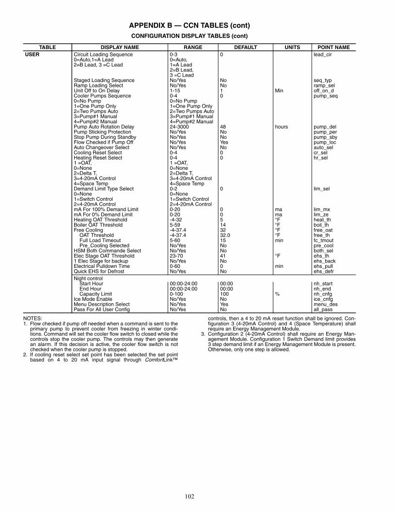
102
APPENDIX B — CCN TABLES (cont)CONFIGURATION DISPLAY TABLES (cont)
NOTES:1. Flow checked if pump off needed when a command is sent to the
primary pump to prevent cooler from freezing in winter condi-tions. Command will set the cooler flow switch to closed while thecontrols stop the cooler pump. The controls may then generatean alarm. If this decision is active, the cooler flow switch is notchecked when the cooler pump is stopped.
2. If cooling reset select set point has been selected the set pointbased on 4 to 20 mA input signal through ComfortLink™
controls, then a 4 to 20 mA reset function shall be ignored. Con-figuration 3 (4-20mA Control) and 4 (Space Temperature) shallrequire an Energy Management Module.
3. Configuration 2 (4-20mA Control) shall require an Energy Man-agement Module. Configuration 1 Switch Demand limit provides3 step demand limit if an Energy Management Module is present.Otherwise, only one step is allowed.
TABLE DISPLAY NAME RANGE DEFAULT UNITS POINT NAMEUSER Circuit Loading Sequence
0=Auto,1=A Lead2=B Lead, 3 =C Lead
0-30=Auto,1=A Lead2=B Lead,3 =C Lead
0 lead_cir
Staged Loading Sequence No/Yes No seq_typRamp Loading Select No/Yes No ramp_selUnit Off to On Delay 1-15 1 Min off_on_dCooler Pumps Sequence0=No Pump1=One Pump Only2=Two Pumps Auto3=Pump#1 Manual4=Pump#2 Manual
0-40=No Pump1=One Pump Only2=Two Pumps Auto3=Pump#1 Manual4=Pump#2 Manual
0 pump_seq
Pump Auto Rotation Delay 24-3000 48 hours pump_delPump Sticking Protection No/Yes No pump_perStop Pump During Standby No/Yes No pump_sbyFlow Checked if Pump Off No/Yes Yes pump_locAuto Changeover Select No/Yes No auto_selCooling Reset Select 0-4 0 cr_selHeating Reset Select1 =OAT, 0=None 2=Delta T,3=4-20mA Control4=Space Temp
0-41 =OAT, 0=None 2=Delta T,3=4-20mA Control4=Space Temp
0 hr_sel
Demand Limit Type Select0=None1=Switch Control2=4-20mA Control
0-20=None1=Switch Control2=4-20mA Control
0 lim_sel
mA For 100% Demand Limit 0-20 0 ma lim_mxmA For 0% Demand Limit 0-20 0 ma lim_zeHeating OAT Threshold -4-32 5 °F heat_thBoiler OAT Threshold 5-59 14 °F boil_thFree Cooling -4-37.4 32 °F free_oat OAT Threshold -4-37.4 32.0 °F free_th Full Load Timeout 5-60 15 min fc_tmout Pre_Cooling Selected No/Yes No pre_coolHSM Both Commande Select No/Yes No both_selElec Stage OAT Threshold 23-70 41 °F ehs_th1 Elec Stage for backup No/Yes No ehs_backElectrical Pulldown Time 0-60 0 min ehs_pullQuick EHS for Defrost No/Yes No ehs_defrNight control Start Hour 00:00-24:00 00:00 nh_start End Hour 00:00-24:00 00:00 nh_end Capacity Limit 0-100 100 % nh_cnfgIce Mode Enable No/Yes No ice_cnfgMenu Description Select No/Yes Yes menu_desPass For All User Config No/Yes No all_pass
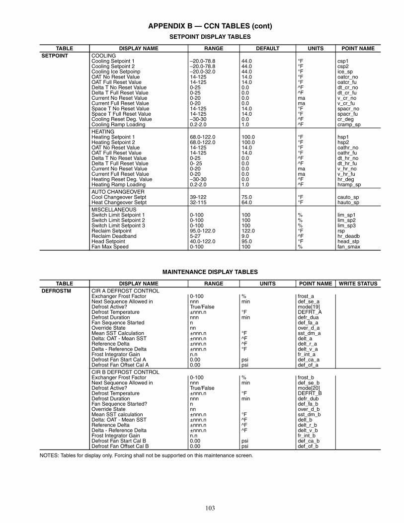
103
APPENDIX B — CCN TABLES (cont)SETPOINT DISPLAY TABLES
MAINTENANCE DISPLAY TABLES
NOTES: Tables for display only. Forcing shall not be supported on this maintenance screen.
TABLE DISPLAY NAME RANGE DEFAULT UNITS POINT NAMESETPOINT COOLING
Cooling Setpoint 1 –20.0-78.8 44.0 °F csp1Cooling Setpoint 2 –20.0-78.8 44.0 °F csp2Cooling Ice Setpoinp –20.0-32.0 44.0 °F ice_spOAT No Reset Value 14-125 14.0 °F oatcr_noOAT Full Reset Value 14-125 14.0 °F oatcr_fuDelta T No Reset Value 0-25 0.0 ^F dt_cr_noDelta T Full Reset Value 0-25 0.0 ^F dt_cr_fuCurrent No Reset Value 0-20 0.0 ma v_cr_noCurrent Full Reset Value 0-20 0.0 ma v_cr_fuSpace T No Reset Value 14-125 14.0 °F spacr_noSpace T Full Reset Value 14-125 14.0 °F spacr_fuCooling Reset Deg. Value –30-30 0.0 ^F cr_degCooling Ramp Loading 0.2-2.0 1.0 ^F cramp_spHEATINGHeating Setpoint 1 68.0-122.0 100.0 °F hsp1Heating Setpoint 2 68.0-122.0 100.0 °F hsp2OAT No Reset Value 14-125 14.0 °F oathr_noOAT Full Reset Value 14-125 14.0 °F oathr_fuDelta T No Reset Value 0-25 0.0 ^F dt_hr_noDelta T Full Reset Value 0- 25 0.0 ^F dt_hr_fuCurrent No Reset Value 0-20 0.0 ma v_hr_noCurrent Full Reset Value 0-20 0.0 ma v_hr_fuHeating Reset Deg. Value –30-30 0.0 ^F hr_degHeating Ramp Loading 0.2-2.0 1.0 ^F hramp_spAUTO CHANGEOVERCool Changeover Setpt 39-122 75.0 °F cauto_spHeat Changeover Setpt 32-115 64.0 °F hauto_spMISCELLANEOUSSwitch Limit Setpoint 1 0-100 100 % lim_sp1Switch Limit Setpoint 2 0-100 100 % lim_sp2Switch Limit Setpoint 3 0-100 100 % lim_sp3Reclaim Setpoint 95.0-122.0 122.0 °F rspReclaim Deadband 5-27 9.0 ^F hr_deadbHead Setpoint 40.0-122.0 95.0 °F head_stpFan Max Speed 0-100 100 % fan_smax
TABLE DISPLAY NAME RANGE UNITS POINT NAME WRITE STATUSDEFROSTM CIR A DEFROST CONTROL
Exchanger Frost Factor 0-100 % frost_aNext Sequence Allowed in nnn min def_se_aDefrost Active? True/False mode[19]Defrost Temperature ±nnn.n °F DEFRT_ADefrost Duration nnn min defr_duaFan Sequence Started n def_fa_aOverride State nn over_d_aMean SST Calculation ±nnn.n °F sst_dm_aDelta: OAT - Mean SST ±nnn.n ^F delt_aReference Delta ±nnn.n ^F delt_r_aDelta - Reference Delta ±nnn.n °F delt_v_aFrost Integrator Gain n.n fr_int_aDefrost Fan Start Cal A 0.00 psi def_ca_aDefrost Fan Offset Cal A 0.00 psi def_of_aCIR B DEFROST CONTROLExchanger Frost Factor 0-100 % frost_bNext Sequence Allowed in nnn min def_se_bDefrost Active? True/False mode[20]Defrost Temperature ±nnn.n °F DEFRT_BDefrost Duration nnn min defr_dubFan Sequence Started? n def_fa_bOverride State nn over_d_bMean SST calculation ±nnn.n °F sst_dm_bDelta: OAT - Mean SST ±nnn.n ^F delt_bReference Delta ±nnn.n ^F delt_r_bDelta - Reference Delta ±nnn.n ^F delt_v_bFrost Integrator Gain n.n fr_int_bDefrost Fan Start Cal B 0.00 psi def_ca_bDefrost Fan Offset Cal B 0.00 psi def_of_b
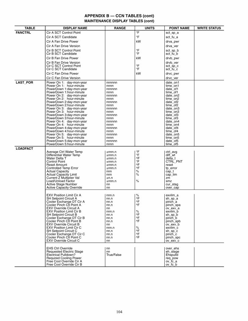
104
APPENDIX B — CCN TABLES (cont)MAINTENANCE DISPLAY TABLES (cont)
TABLE DISPLAY NAME RANGE UNITS POINT NAME WRITE STATUSFANCTRL Cir A SCT Control Point °F sct_sp_a
Cir A SCT Candidate °F sct_fu_aCir A Fan Drive Power kW drva_pwrCir A Fan Drive Version drva_verCir B SCT Control Point °F sct_sp_bCir B SCT Candidate °F sct_fu_bCir B Fan Drive Power kW drvb_pwrCir B Fan Drive Version drvb_verCir C SCT Control Point °F sct_sp_cCir C SCT Candidate °F sct_fu_cCir C Fan Drive Power kW drvc_pwrCir C Fan Drive Version drvc_ver
LAST_POR Power On 1: day-mon-year nnnnnn date_on1Power On 1: hour-minute nnnn time_on1PowerDown 1:day-mon-year nnnnnn date_of1PowerDown 1:hour-minute nnnn time_of1Power On 2: day-mon-year nnnnnn date_on2Power On 2: hour-minute nnnn time_on2PowerDown 2:day-mon-year nnnnnn date_of2PowerDown 2:hour-minute nnnn time_of2Power On 3: day-mon-year nnnnnn date_on3Power On 3: hour-minute nnnn time_on3PowerDown 3:day-mon-year nnnnnn date_of3PowerDown 3:hour-minute nnnn time_of3Power On 4: day-mon-year nnnnnn date_on4Power On 4: hour-minute nnnn time_on4PowerDown 4:day-mon-year nnnnnn date_of4PowerDown 4:hour-minute nnnn time_of4Power On 5: day-mon-year nnnnnn date_on5Power On 5: hour-minute nnnn time_on5PowerDown 5:day-mon-year nnnnnn date_of5PowerDown 5:hour-minute nnnn time_of5
LOADFACTAverage Ctrl Water Temp ±nnn.n °F ctrl_avgDifferential Water Temp ±nnn.n °F diff_wtWater Delta T ±nnn.n ^F delta_tControl Point ±nnn.n °F CTRL_PNTReset Amount ±nnn.n ^F resetControlled Temp Error ±nnn.n ^F tp_errorActual Capacity nnn % cap_tActual Capacity Limit nnn % cap_limCurrent Z Multiplier Val ±n.n zmLoad/Unload Factor ±nnn.n % smzActive Stage Number nn cur_stagActive Capacity Override nn over_cap
EXV Position Limit Cir A nnn.n % exvlim_aSH Setpoint Circuit A nn.n ^F sh_sp_aCooler Exchange DT Cir A nn.n ^F pinch_aCooler Pinch Ctl Point A nn.n ^F pinch_spaEXV Override Circuit A nn ov_exv_aEXV Position Limit Cir B nnn.n % exvlim_bSH Setpoint Circuit B nn.n ^F sh_sp_bCooler Exchange DT Cir B nn.n ^F pinch_bCooler Pinch Ctl Point B nn.n ^F pinch_spbEXV Override Circuit B nn ov_exv_bEXV Position Limit Cir C nnn.n % exvlim_cSH Setpoint Circuit C nn.n ^F sh_sp_cCooler Exchange DT Cir C nn.n ^F pinch_cCooler Pinch Ctl Point C nn.n ^F pinch_spcEXV Override Circuit C nn ov_exv_c
EHS Ctrl Override nn over_ehsRequested Electric Stage nn eh_stageElectrical Pulldown? True/False EhspulldRequired Cooling Power req_powFree Cool Override Cir A ov_fc_aFree Cool Override Cir B ov_fc_b
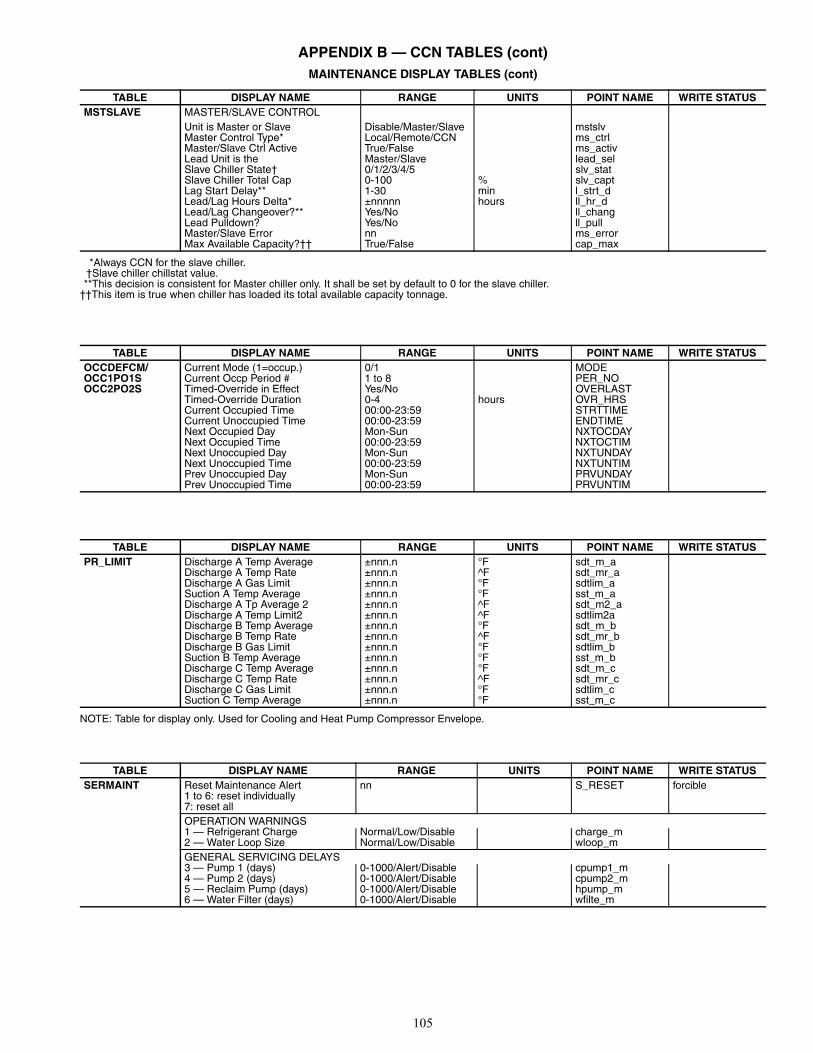
105
APPENDIX B — CCN TABLES (cont)MAINTENANCE DISPLAY TABLES (cont)
*Always CCN for the slave chiller.†Slave chiller chillstat value.**This decision is consistent for Master chiller only. It shall be set by default to 0 for the slave chiller.
††This item is true when chiller has loaded its total available capacity tonnage.
NOTE: Table for display only. Used for Cooling and Heat Pump Compressor Envelope.
TABLE DISPLAY NAME RANGE UNITS POINT NAME WRITE STATUSMSTSLAVE MASTER/SLAVE CONTROL
Unit is Master or Slave Disable/Master/Slave mstslvMaster Control Type* Local/Remote/CCN ms_ctrlMaster/Slave Ctrl Active True/False ms_activLead Unit is the Master/Slave lead_selSlave Chiller State† 0/1/2/3/4/5 slv_statSlave Chiller Total Cap 0-100 % slv_captLag Start Delay** 1-30 min l_strt_dLead/Lag Hours Delta* ±nnnnn hours ll_hr_dLead/Lag Changeover?** Yes/No ll_changLead Pulldown? Yes/No ll_pullMaster/Slave Error nn ms_errorMax Available Capacity?†† True/False cap_max
TABLE DISPLAY NAME RANGE UNITS POINT NAME WRITE STATUSOCCDEFCM/OCC1PO1S OCC2PO2S
Current Mode (1=occup.) 0/1 MODECurrent Occp Period # 1 to 8 PER_NOTimed-Override in Effect Yes/No OVERLASTTimed-Override Duration 0-4 hours OVR_HRSCurrent Occupied Time 00:00-23:59 STRTTIMECurrent Unoccupied Time 00:00-23:59 ENDTIMENext Occupied Day Mon-Sun NXTOCDAYNext Occupied Time 00:00-23:59 NXTOCTIMNext Unoccupied Day Mon-Sun NXTUNDAYNext Unoccupied Time 00:00-23:59 NXTUNTIMPrev Unoccupied Day Mon-Sun PRVUNDAYPrev Unoccupied Time 00:00-23:59 PRVUNTIM
TABLE DISPLAY NAME RANGE UNITS POINT NAME WRITE STATUSPR_LIMIT Discharge A Temp Average ±nnn.n °F sdt_m_a
Discharge A Temp Rate ±nnn.n ^F sdt_mr_aDischarge A Gas Limit ±nnn.n °F sdtlim_aSuction A Temp Average ±nnn.n °F sst_m_aDischarge A Tp Average 2 ±nnn.n ^F sdt_m2_aDischarge A Temp Limit2 ±nnn.n ^F sdtlim2aDischarge B Temp Average ±nnn.n °F sdt_m_bDischarge B Temp Rate ±nnn.n ^F sdt_mr_bDischarge B Gas Limit ±nnn.n °F sdtlim_bSuction B Temp Average ±nnn.n °F sst_m_bDischarge C Temp Average ±nnn.n °F sdt_m_cDischarge C Temp Rate ±nnn.n ^F sdt_mr_cDischarge C Gas Limit ±nnn.n °F sdtlim_cSuction C Temp Average ±nnn.n °F sst_m_c
TABLE DISPLAY NAME RANGE UNITS POINT NAME WRITE STATUSSERMAINT Reset Maintenance Alert
1 to 6: reset individually7: reset all
nn S_RESET forcible
OPERATION WARNINGS1 — Refrigerant Charge Normal/Low/Disable charge_m2 — Water Loop Size Normal/Low/Disable wloop_mGENERAL SERVICING DELAYS3 — Pump 1 (days) 0-1000/Alert/Disable cpump1_m4 — Pump 2 (days) 0-1000/Alert/Disable cpump2_m5 — Reclaim Pump (days) 0-1000/Alert/Disable hpump_m6 — Water Filter (days) 0-1000/Alert/Disable wfilte_m
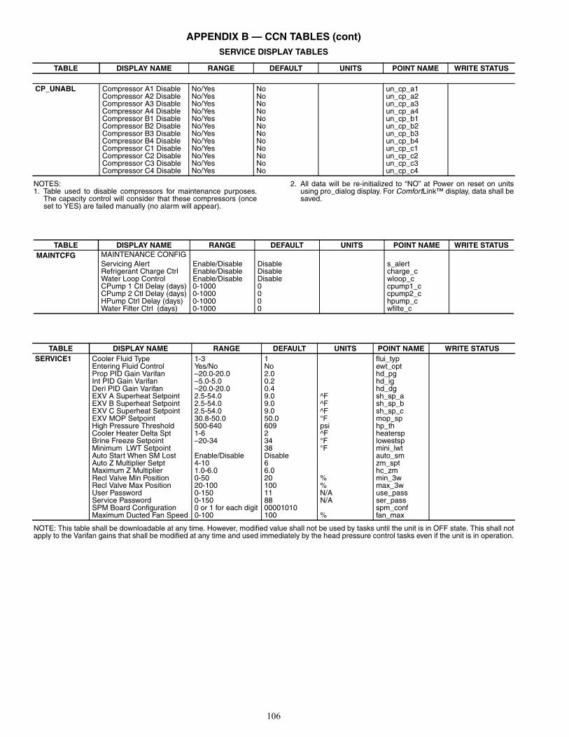
106
APPENDIX B — CCN TABLES (cont)SERVICE DISPLAY TABLES
NOTES:1. Table used to disable compressors for maintenance purposes.
The capacity control will consider that these compressors (onceset to YES) are failed manually (no alarm will appear).
2. All data will be re-initialized to “NO” at Power on reset on unitsusing pro_dialog display. For ComfortLink™ display, data shall besaved.
NOTE: This table shall be downloadable at any time. However, modified value shall not be used by tasks until the unit is in OFF state. This shall notapply to the Varifan gains that shall be modified at any time and used immediately by the head pressure control tasks even if the unit is in operation.
TABLE DISPLAY NAME RANGE DEFAULT UNITS POINT NAME WRITE STATUS
CP_UNABL Compressor A1 Disable No/Yes No un_cp_a1Compressor A2 Disable No/Yes No un_cp_a2Compressor A3 Disable No/Yes No un_cp_a3Compressor A4 Disable No/Yes No un_cp_a4Compressor B1 Disable No/Yes No un_cp_b1Compressor B2 Disable No/Yes No un_cp_b2Compressor B3 Disable No/Yes No un_cp_b3Compressor B4 Disable No/Yes No un_cp_b4Compressor C1 Disable No/Yes No un_cp_c1Compressor C2 Disable No/Yes No un_cp_c2Compressor C3 Disable No/Yes No un_cp_c3Compressor C4 Disable No/Yes No un_cp_c4
TABLE DISPLAY NAME RANGE DEFAULT UNITS POINT NAME WRITE STATUSMAINTCFG MAINTENANCE CONFIG
Servicing Alert Enable/Disable Disable s_alertRefrigerant Charge Ctrl Enable/Disable Disable charge_cWater Loop Control Enable/Disable Disable wloop_cCPump 1 Ctl Delay (days) 0-1000 0 cpump1_cCPump 2 Ctl Delay (days) 0-1000 0 cpump2_cHPump Ctrl Delay (days) 0-1000 0 hpump_cWater Filter Ctrl (days) 0-1000 0 wfilte_c
TABLE DISPLAY NAME RANGE DEFAULT UNITS POINT NAME WRITE STATUSSERVICE1 Cooler Fluid Type 1-3 1 flui_typ
Entering Fluid Control Yes/No No ewt_optProp PID Gain Varifan –20.0-20.0 2.0 hd_pgInt PID Gain Varifan –5.0-5.0 0.2 hd_igDeri PID Gain Varifan –20.0-20.0 0.4 hd_dgEXV A Superheat Setpoint 2.5-54.0 9.0 ^F sh_sp_aEXV B Superheat Setpoint 2.5-54.0 9.0 ^F sh_sp_bEXV C Superheat Setpoint 2.5-54.0 9.0 ^F sh_sp_cEXV MOP Setpoint 30.8-50.0 50.0 °F mop_spHigh Pressure Threshold 500-640 609 psi hp_thCooler Heater Delta Spt 1-6 2 ^F heaterspBrine Freeze Setpoint –20-34 34 °F lowestspMinimum LWT Setpoint 38 °F mini_lwtAuto Start When SM Lost Enable/Disable Disable auto_smAuto Z Multiplier Setpt 4-10 6 zm_sptMaximum Z Multiplier 1.0-6.0 6.0 hc_zmRecl Valve Min Position 0-50 20 % min_3wRecl Valve Max Position 20-100 100 % max_3wUser Password 0-150 11 N/A use_passService Password 0-150 88 N/A ser_passSPM Board Configuration 0 or 1 for each digit 00001010 spm_confMaximum Ducted Fan Speed 0-100 100 % fan_max
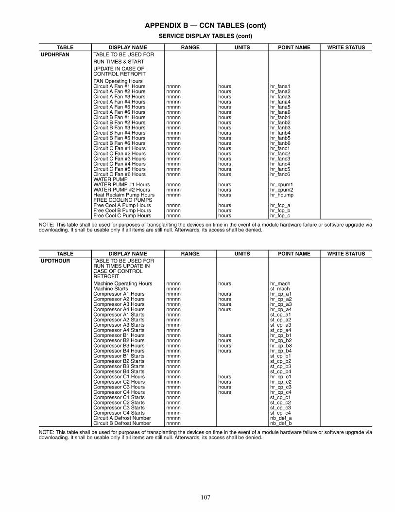
107
APPENDIX B — CCN TABLES (cont)SERVICE DISPLAY TABLES (cont)
NOTE: This table shall be used for purposes of transplanting the devices on time in the event of a module hardware failure or software upgrade viadownloading. It shall be usable only if all items are still null. Afterwards, its access shall be denied.
NOTE: This table shall be used for purposes of transplanting the devices on time in the event of a module hardware failure or software upgrade viadownloading. It shall be usable only if all items are still null. Afterwards, its access shall be denied.
TABLE DISPLAY NAME RANGE UNITS POINT NAME WRITE STATUSUPDHRFAN TABLE TO BE USED FOR
RUN TIMES & STARTUPDATE IN CASE OFCONTROL RETROFITFAN Operating HoursCircuit A Fan #1 Hours nnnnn hours hr_fana1Circuit A Fan #2 Hours nnnnn hours hr_fana2Circuit A Fan #3 Hours nnnnn hours hr_fana3Circuit A Fan #4 Hours nnnnn hours hr_fana4Circuit A Fan #5 Hours nnnnn hours hr_fana5Circuit A Fan #6 Hours nnnnn hours hr_fana6Circuit B Fan #1 Hours nnnnn hours hr_fanb1Circuit B Fan #2 Hours nnnnn hours hr_fanb2Circuit B Fan #3 Hours nnnnn hours hr_fanb3Circuit B Fan #4 Hours nnnnn hours hr_fanb4Circuit B Fan #5 Hours nnnnn hours hr_fanb5Circuit B Fan #6 Hours nnnnn hours hr_fanb6Circuit C Fan #1 Hours nnnnn hours hr_fanc1Circuit C Fan #2 Hours nnnnn hours hr_fanc2Circuit C Fan #3 Hours nnnnn hours hr_fanc3Circuit C Fan #4 Hours nnnnn hours hr_fanc4Circuit C Fan #5 Hours nnnnn hours hr_fanc5Circuit C Fan #6 Hours nnnnn hours hr_fanc6WATER PUMPWATER PUMP #1 Hours nnnnn hours hr_cpum1WATER PUMP #2 Hours nnnnn hours hr_cpum2Heat Reclaim Pump Hours nnnnn hours hr_hpumpFREE COOLING PUMPSFree Cool A Pump Hours nnnnn hours hr_fcp_aFree Cool B Pump Hours nnnnn hours hr_fcp_bFree Cool C Pump Hours nnnnn hours hr_fcp_c
TABLE DISPLAY NAME RANGE UNITS POINT NAME WRITE STATUSUPDTHOUR TABLE TO BE USED FOR
RUN TIMES UPDATE IN CASE OF CONTROL RETROFITMachine Operating Hours nnnnn hours hr_machMachine Starts nnnnn st_machCompressor A1 Hours nnnnn hours hr_cp_a1Compressor A2 Hours nnnnn hours hr_cp_a2Compressor A3 Hours nnnnn hours hr_cp_a3Compressor A4 Hours nnnnn hours hr_cp_a4Compressor A1 Starts nnnnn st_cp_a1Compressor A2 Starts nnnnn st_cp_a2Compressor A3 Starts nnnnn st_cp_a3Compressor A4 Starts nnnnn st_cp_a4Compressor B1 Hours nnnnn hours hr_cp_b1Compressor B2 Hours nnnnn hours hr_cp_b2Compressor B3 Hours nnnnn hours hr_cp_b3Compressor B4 Hours nnnnn hours hr_cp_b4Compressor B1 Starts nnnnn st_cp_b1Compressor B2 Starts nnnnn st_cp_b2Compressor B3 Starts nnnnn st_cp_b3Compressor B4 Starts nnnnn st_cp_b4Compressor C1 Hours nnnnn hours hr_cp_c1Compressor C2 Hours nnnnn hours hr_cp_c2Compressor C3 Hours nnnnn hours hr_cp_c3Compressor C4 Hours nnnnn hours hr_cp_c4Compressor C1 Starts nnnnn st_cp_c1Compressor C2 Starts nnnnn st_cp_c2Compressor C3 Starts nnnnn st_cp_c3Compressor C4 Starts nnnnn st_cp_c4Circuit A Defrost Number nnnnn nb_def_aCircuit B Defrost Number nnnnn nb_def_b
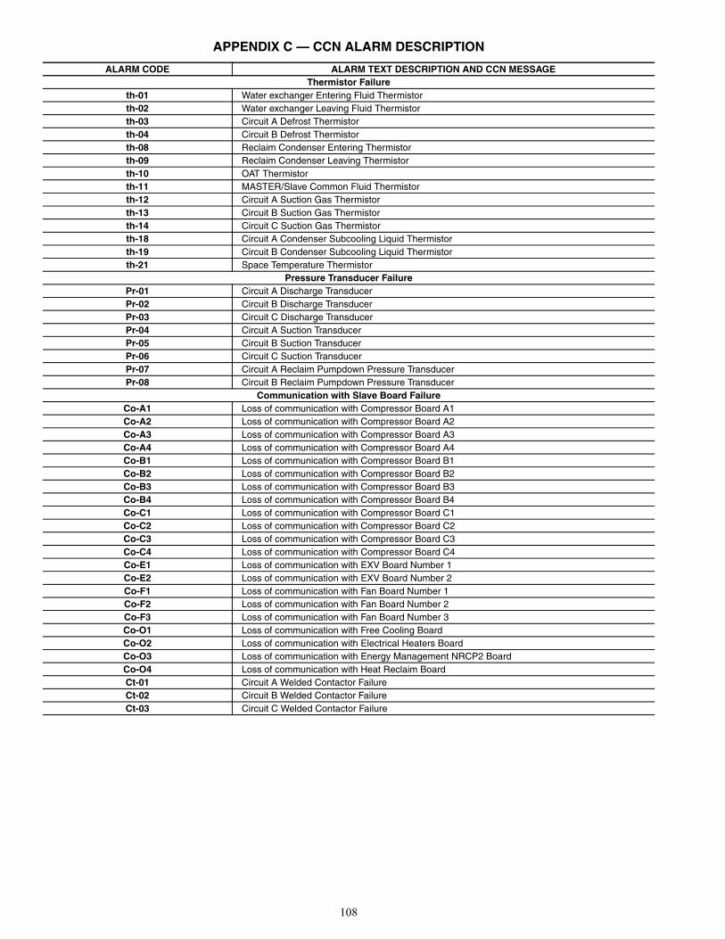
108
APPENDIX C — CCN ALARM DESCRIPTION
ALARM CODE ALARM TEXT DESCRIPTION AND CCN MESSAGEThermistor Failure
th-01 Water exchanger Entering Fluid Thermistorth-02 Water exchanger Leaving Fluid Thermistorth-03 Circuit A Defrost Thermistorth-04 Circuit B Defrost Thermistorth-08 Reclaim Condenser Entering Thermistorth-09 Reclaim Condenser Leaving Thermistorth-10 OAT Thermistorth-11 MASTER/Slave Common Fluid Thermistorth-12 Circuit A Suction Gas Thermistor th-13 Circuit B Suction Gas Thermistor th-14 Circuit C Suction Gas Thermistor th-18 Circuit A Condenser Subcooling Liquid Thermistorth-19 Circuit B Condenser Subcooling Liquid Thermistorth-21 Space Temperature Thermistor
Pressure Transducer FailurePr-01 Circuit A Discharge TransducerPr-02 Circuit B Discharge Transducer Pr-03 Circuit C Discharge Transducer Pr-04 Circuit A Suction TransducerPr-05 Circuit B Suction TransducerPr-06 Circuit C Suction Transducer Pr-07 Circuit A Reclaim Pumpdown Pressure Transducer Pr-08 Circuit B Reclaim Pumpdown Pressure Transducer
Communication with Slave Board FailureCo-A1 Loss of communication with Compressor Board A1 Co-A2 Loss of communication with Compressor Board A2 Co-A3 Loss of communication with Compressor Board A3Co-A4 Loss of communication with Compressor Board A4 Co-B1 Loss of communication with Compressor Board B1 Co-B2 Loss of communication with Compressor Board B2Co-B3 Loss of communication with Compressor Board B3 Co-B4 Loss of communication with Compressor Board B4Co-C1 Loss of communication with Compressor Board C1 Co-C2 Loss of communication with Compressor Board C2 Co-C3 Loss of communication with Compressor Board C3 Co-C4 Loss of communication with Compressor Board C4 Co-E1 Loss of communication with EXV Board Number 1 Co-E2 Loss of communication with EXV Board Number 2 Co-F1 Loss of communication with Fan Board Number 1Co-F2 Loss of communication with Fan Board Number 2 Co-F3 Loss of communication with Fan Board Number 3Co-O1 Loss of communication with Free Cooling Board Co-O2 Loss of communication with Electrical Heaters BoardCo-O3 Loss of communication with Energy Management NRCP2 BoardCo-O4 Loss of communication with Heat Reclaim Board Ct-01 Circuit A Welded Contactor FailureCt-02 Circuit B Welded Contactor FailureCt-03 Circuit C Welded Contactor Failure
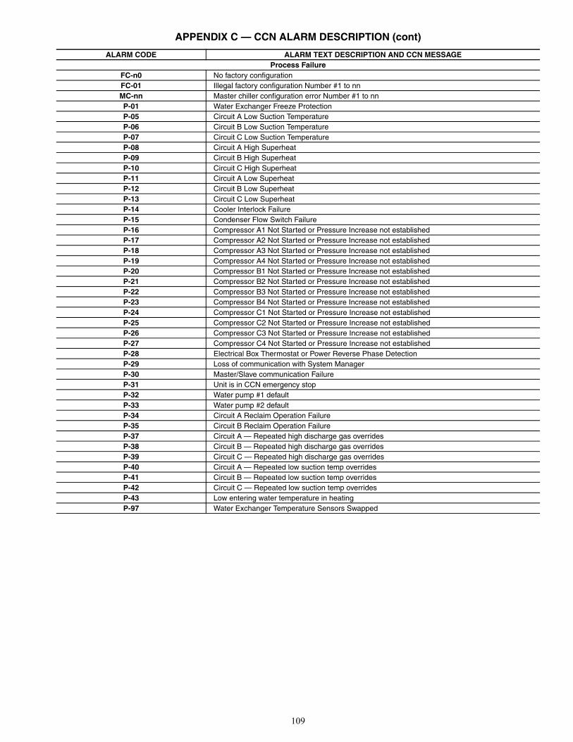
109
APPENDIX C — CCN ALARM DESCRIPTION (cont)
ALARM CODE ALARM TEXT DESCRIPTION AND CCN MESSAGEProcess Failure
FC-n0 No factory configurationFC-01 Illegal factory configuration Number #1 to nnMC-nn Master chiller configuration error Number #1 to nn P-01 Water Exchanger Freeze Protection P-05 Circuit A Low Suction Temperature P-06 Circuit B Low Suction Temperature P-07 Circuit C Low Suction TemperatureP-08 Circuit A High SuperheatP-09 Circuit B High SuperheatP-10 Circuit C High SuperheatP-11 Circuit A Low SuperheatP-12 Circuit B Low SuperheatP-13 Circuit C Low SuperheatP-14 Cooler Interlock FailureP-15 Condenser Flow Switch FailureP-16 Compressor A1 Not Started or Pressure Increase not establishedP-17 Compressor A2 Not Started or Pressure Increase not establishedP-18 Compressor A3 Not Started or Pressure Increase not establishedP-19 Compressor A4 Not Started or Pressure Increase not establishedP-20 Compressor B1 Not Started or Pressure Increase not establishedP-21 Compressor B2 Not Started or Pressure Increase not establishedP-22 Compressor B3 Not Started or Pressure Increase not establishedP-23 Compressor B4 Not Started or Pressure Increase not establishedP-24 Compressor C1 Not Started or Pressure Increase not establishedP-25 Compressor C2 Not Started or Pressure Increase not establishedP-26 Compressor C3 Not Started or Pressure Increase not establishedP-27 Compressor C4 Not Started or Pressure Increase not establishedP-28 Electrical Box Thermostat or Power Reverse Phase DetectionP-29 Loss of communication with System ManagerP-30 Master/Slave communication FailureP-31 Unit is in CCN emergency stop P-32 Water pump #1 defaultP-33 Water pump #2 defaultP-34 Circuit A Reclaim Operation FailureP-35 Circuit B Reclaim Operation FailureP-37 Circuit A — Repeated high discharge gas overrides P-38 Circuit B — Repeated high discharge gas overridesP-39 Circuit C — Repeated high discharge gas overrides P-40 Circuit A — Repeated low suction temp overridesP-41 Circuit B — Repeated low suction temp overridesP-42 Circuit C — Repeated low suction temp overridesP-43 Low entering water temperature in heatingP-97 Water Exchanger Temperature Sensors Swapped
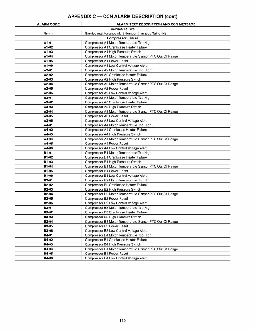
110
APPENDIX C — CCN ALARM DESCRIPTION (cont)
ALARM CODE ALARM TEXT DESCRIPTION AND CCN MESSAGEService Failure
Sr-nn Service maintenance alert Number # nn (see Table 44)Compressor Failure
A1-01 Compressor A1 Motor Temperature Too HighA1-02 Compressor A1 Crankcase Heater FailureA1-03 Compressor A1 High Pressure SwitchA1-04 Compressor A1 Motor Temperature Sensor PTC Out Of RangeA1-05 Compressor A1 Power ResetA1-06 Compressor A1 Low Control Voltage AlertA2-01 Compressor A2 Motor Temperature Too HighA2-02 Compressor A2 Crankcase Heater FailureA2-03 Compressor A2 High Pressure SwitchA2-04 Compressor A2 Motor Temperature Sensor PTC Out Of RangeA2-05 Compressor A2 Power ResetA2-06 Compressor A2 Low Control Voltage AlertA3-01 Compressor A3 Motor Temperature Too HighA3-02 Compressor A3 Crankcase Heater FailureA3-03 Compressor A3 High Pressure SwitchA3-04 Compressor A3 Motor Temperature Sensor PTC Out Of RangeA3-05 Compressor A3 Power ResetA3-06 Compressor A3 Low Control Voltage AlertA4-01 Compressor A4 Motor Temperature Too HighA4-02 Compressor A4 Crankcase Heater FailureA4-03 Compressor A4 High Pressure SwitchA4-04 Compressor A4 Motor Temperature Sensor PTC Out Of RangeA4-05 Compressor A4 Power ResetA4-06 Compressor A4 Low Control Voltage AlertB1-01 Compressor B1 Motor Temperature Too HighB1-02 Compressor B1 Crankcase Heater Failure B1-03 Compressor B1 High Pressure SwitchB1-04 Compressor B1 Motor Temperature Sensor PTC Out Of RangeB1-05 Compressor B1 Power ResetB1-06 Compressor B1 Low Control Voltage AlertB2-01 Compressor B2 Motor Temperature Too HighB2-02 Compressor B2 Crankcase Heater FailureB2-03 Compressor B2 High Pressure SwitchB2-04 Compressor B2 Motor Temperature Sensor PTC Out Of RangeB2-05 Compressor B2 Power ResetB2-06 Compressor B2 Low Control Voltage AlertB3-01 Compressor B3 Motor Temperature Too HighB3-02 Compressor B3 Crankcase Heater FailureB3-03 Compressor B3 High Pressure SwitchB3-04 Compressor B3 Motor Temperature Sensor PTC Out Of RangeB3-05 Compressor B3 Power ResetB3-06 Compressor B3 Low Control Voltage AlertB4-01 Compressor B4 Motor Temperature Too HighB4-02 Compressor B4 Crankcase Heater FailureB4-03 Compressor B4 High Pressure SwitchB4-04 Compressor B4 Motor Temperature Sensor PTC Out Of RangeB4-05 Compressor B4 Power ResetB4-06 Compressor B4 Low Control Voltage Alert

111
APPENDIX C — CCN ALARM DESCRIPTION (cont)
ALARM CODE ALARM TEXT DESCRIPTION AND CCN MESSAGECompressor Failure
C1-01 Compressor C1 Motor Temperature Too HighC1-02 Compressor C1 Crankcase Heater FailureC1-03 Compressor C1 High Pressure SwitchC1-04 Compressor C1 Motor Temperature Sensor PTC Out Of RangeC1-05 Compressor C1 Power ResetC1-06 Compressor C1 Low Control Voltage AlertC2-01 Compressor C2 Motor Temperature Too HighC2-02 Compressor C2 Crankcase Heater FailureC2-03 Compressor C2 High Pressure SwitchC2-04 Compressor C2 Motor Temperature Sensor PTC Out Of RangeC2-05 Compressor C2 Power ResetC2-06 Compressor C2 Low Control Voltage AlertC3-01 Compressor C3 Motor Temperature Too HighC3-02 Compressor C3 Crankcase Heater FailureC3-03 Compressor C3 High Pressure SwitchC3-04 Compressor C3 Motor Temperature Sensor PTC Out Of RangeC3-05 Compressor C3 Power ResetC3-06 Compressor C3 Low Control Voltage AlertC4-01 Compressor C4 Motor Temperature Too HighC4-02 Compressor C4 Crankcase Heater FailureC4-03 Compressor C4 High Pressure SwitchC4-04 Compressor C4 Motor Temperature Sensor PTC Out Of RangeC4-05 Compressor C4 Power ResetC4-06 Compressor C4 Low Control Voltage Alert

112
APPENDIX D — R-410A PRESSURE VS. TEMPERATURE CHART
PSIG °F °C PSIG °F °C PSIG °F °C PSIG °F °C PSIG °F °C PSIG °F °C12 –37.7 –38.7 114 37.8 3.2 216 74.3 23.5 318 100.2 37.9 420 120.7 49.3 522 137.6 58.714 –34.7 –37.1 116 38.7 3.7 218 74.9 23.8 320 100.7 38.2 422 121.0 49.4 524 137.9 58.816 –32.0 –35.6 118 39.5 4.2 220 75.5 24.2 322 101.1 38.4 424 121.4 49.7 526 138.3 59.118 –29.4 –34.1 120 40.5 4.7 222 76.1 24.5 324 101.6 38.7 426 121.7 49.8 528 138.6 59.220 –26.9 –32.7 122 41.3 5.2 224 76.7 24.8 326 102.0 38.9 428 122.1 50.1 530 138.9 59.422 –24.5 –31.4 124 42.2 5.7 226 77.2 25.1 328 102.4 39.1 430 122.5 50.3 532 139.2 59.624 –22.2 –30.1 126 43.0 6.1 228 77.8 25.4 330 102.9 39.4 432 122.8 50.4 534 139.5 59.726 –20.0 –28.9 128 43.8 6.6 230 78.4 25.8 332 103.3 39.6 434 123.2 50.7 536 139.8 59.928 –17.9 –27.7 130 44.7 7.1 232 78.9 26.1 334 103.7 39.8 436 123.5 50.8 538 140.1 60.130 –15.8 –26.6 132 45.5 7.5 234 79.5 26.4 336 104.2 40.1 438 123.9 51.1 540 140.4 60.232 –13.8 –25.4 134 46.3 7.9 236 80.0 26.7 338 104.6 40.3 440 124.2 51.2 544 141.0 60.634 –11.9 –24.4 136 47.1 8.4 238 80.6 27.0 340 105.1 40.6 442 124.6 51.4 548 141.6 60.936 –10.1 –23.4 138 47.9 8.8 240 81.1 27.3 342 105.4 40.8 444 124.9 51.6 552 142.1 61.238 –8.3 –22.4 140 48.7 9.3 242 81.6 27.6 344 105.8 41.0 446 125.3 51.8 556 142.7 61.540 –6.5 –21.4 142 49.5 9.7 244 82.2 27.9 346 106.3 41.3 448 125.6 52.0 560 143.3 61.842 –4.5 –20.3 144 50.3 10.2 246 82.7 28.2 348 106.6 41.4 450 126.0 52.2 564 143.9 62.244 –3.2 –19.6 146 51.1 10.6 248 83.3 28.5 350 107.1 41.7 452 126.3 52.4 568 144.5 62.546 –1.6 –18.7 148 51.8 11.0 250 83.8 28.8 352 107.5 41.9 454 126.6 52.6 572 145.0 62.848 0.0 –17.8 150 52.5 11.4 252 84.3 29.1 354 107.9 42.2 456 127.0 52.8 576 145.6 63.150 1.5 –16.9 152 53.3 11.8 254 84.8 29.3 356 108.3 42.4 458 127.3 52.9 580 146.2 63.452 3.0 –16.1 154 54.0 12.2 256 85.4 29.7 358 108.8 42.7 460 127.7 53.2 584 146.7 63.754 4.5 –15.3 156 54.8 12.7 258 85.9 29.9 360 109.2 42.9 462 128.0 53.3 588 147.3 64.156 5.9 –14.5 158 55.5 13.1 260 86.4 30.2 362 109.6 43.1 464 128.3 53.5 592 147.9 64.458 7.3 –13.7 160 56.2 13.4 262 86.9 30.5 364 110.0 43.3 466 128.7 53.7 596 148.4 64.760 8.6 –13.0 162 57.0 13.9 264 87.4 30.8 366 110.4 43.6 468 129.0 53.9 600 149.0 65.062 10.0 –12.2 164 57.7 14.3 266 87.9 31.1 368 110.8 43.8 470 129.3 54.1 604 149.5 65.364 11.3 –11.5 166 58.4 14.7 268 88.4 31.3 370 111.2 44.0 472 129.7 54.3 608 150.1 65.666 12.6 –10.8 168 59.0 15.0 270 88.9 31.6 372 111.6 44.2 474 130.0 54.4 612 150.6 65.968 13.8 –10.1 170 59.8 15.4 272 89.4 31.9 374 112.0 44.4 476 130.3 54.6 616 151.2 66.270 15.1 –9.4 172 60.5 15.8 274 89.9 32.2 376 112.4 44.7 478 130.7 54.8 620 151.7 66.572 16.3 –8.7 174 61.1 16.2 276 90.4 32.4 378 112.6 44.8 480 131.0 55.0 624 152.3 66.874 17.5 –8.1 176 61.8 16.6 278 90.9 32.7 380 113.1 45.1 482 131.3 55.2 628 152.8 67.176 18.7 –7.4 178 62.5 16.9 280 91.4 33.0 382 113.5 45.3 484 131.6 55.3 632 153.4 67.478 19.8 –6.8 180 63.1 17.3 282 91.9 33.3 384 113.9 45.5 486 132.0 55.6 636 153.9 67.780 21.0 –6.1 182 63.8 17.7 284 92.4 33.6 386 114.3 45.7 488 132.3 55.7 640 154.5 68.182 22.1 –5.5 184 64.5 18.1 286 92.8 33.8 388 114.7 45.9 490 132.6 55.9 644 155.0 68.384 23.2 –4.9 186 65.1 18.4 288 93.3 34.1 390 115.0 46.1 492 132.9 56.1 648 155.5 68.686 24.3 –4.3 188 65.8 18.8 290 93.8 34.3 392 115.5 46.4 494 133.3 56.3 652 156.1 68.988 25.4 –3.7 190 66.4 19.1 292 94.3 34.6 394 115.8 46.6 496 133.6 56.4 656 156.6 69.290 26.4 –3.1 192 67.0 19.4 294 94.8 34.9 396 116.2 46.8 498 133.9 56.6 660 157.1 69.592 27.4 –2.6 194 67.7 19.8 296 95.2 35.1 398 116.6 47.0 500 134.0 56.7 664 157.7 69.894 28.5 –1.9 196 68.3 20.2 298 95.7 35.4 400 117.0 47.2 502 134.5 56.9 668 158.2 70.196 29.5 –1.4 198 68.9 20.5 300 96.2 35.7 402 117.3 47.4 504 134.8 57.1 672 158.7 70.498 30.5 –0.8 200 69.5 20.8 302 96.6 35.9 404 117.7 47.6 506 135.2 57.3 676 159.2 70.7
100 31.2 –0.4 202 70.1 21.2 304 97.1 36.2 406 118.1 47.8 508 135.5 57.5 680 159.8 71.0102 32.2 0.1 204 70.7 21.5 306 97.5 36.4 408 118.5 48.1 510 135.8 57.7 684 160.3 71.3104 33.2 0.7 206 71.4 21.9 308 98.0 36.7 410 118.8 48.2 512 136.1 57.8 688 160.8 71.6106 34.1 1.2 208 72.0 22.2 310 98.4 36.9 412 119.2 48.4 514 136.4 58.0 692 161.3 71.8108 35.1 1.7 210 72.6 22.6 312 98.9 37.2 414 119.6 48.7 516 136.7 58.2 696 161.8 72.1110 35.5 1.9 212 73.2 22.9 314 99.3 37.4 416 119.9 48.8 518 137.0 58.3112 36.9 2.7 214 73.8 23.2 316 99.7 37.6 418 120.3 49.1 520 137.3 58.5
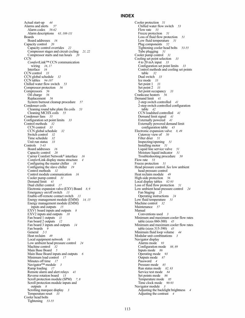
113
INDEXActual start-up 44Alarms and alerts 57
Alarm codes 58-62Alarm descriptions 63, 108-111
BoardsBoard addresses 16
Capacity control 20Capacity control overrides 22Compressor stages and circuit cycling 21, 22Compressor starts and run hours 20
CCNComfortLink™ CCN communication
wiring 16, 17Interface 16
CCN control 33CCN global schedule 32CCN tables 94-107Chilled water flow switch 53Compressor protection 56Compressors 56
Oil charge 56Replacement 56System burnout cleanup procedure 57
Condenser coilsCleaning round tube plate fin coils 53Cleaning MCHX coils 55
Condenser fans 55Configuration set point limits 33Control methods 32
CCN control 33CCN global schedule 32Switch control 32Time schedule 32Unit run status 33
Controls 5-43Board addresses 16Capacity control 20Carrier Comfort Network® interface 16ComfortLink display menu structure 4Configuring the master chiller 18Configuring the slave chiller 19Control methods 32Control module communication 16Cooler pump control 31Demand limit 41Dual chiller control 17Electronic expansion valve (EXV) Board 8, 9Emergency on/off switch 13Enable-off-remote contact switch 13Energy management module (EMM) 14, 15Energy management module (EMM)
inputs and outputs 15EXV1 board inputs and outputs 8EXV2 inputs and outputs 10Fan board 1 outputs 11Fan board 2 outputs 12Fan board 3 inputs and outputs 14Fan boards 9General 2-5Heat reclaim 49Local equipment network 16Low ambient head pressure control 24Machine control 32Main Base Board 5Main Base Board inputs and outputs 6Minimum load control 17Minutes off time 17Navigator™ module 3Ramp loading 17Remote alarm and alert relays 41Reverse rotation board 13Scroll protection module (SPM) 7, 8Scroll protection module inputs and
outputs 8Scrolling marquee display 3Temperature reset 33
Cooler head boltsTightening 53-55
Cooler protection 51Chilled water flow switch 53Flow rate 53Freeze protection 51Loss of fluid flow protection 51Low fluid temperature 51Plug components 52Tightening cooler head bolts 53-55Tube plugging 51
Cooler pump control 31Cooling set point selection 33
4 to 20 mA input 33Configuration set point limits 33Control methods and cooling set points
table 32Dual switch 33Ice mode 33Set point 1 33Set point 2 33Set point occupancy 33
Crankcase heaters 56Demand limit 41
2-step switch controlled 412-step switch controlled configuration
table 42CCN loadshed controlled 41Demand limit signal 41Externally powered 41Externally powered demand limit
configuration table 43Electronic expansion valve 8, 49
Cutaway view of 50Filter drier 51Inspecting/opening 51Installing motor 51Liquid line service valve 51Moisture liquid indicator 51Troubleshooting procedure 50
Flow rate 53Freeze protection 51Head pressure control. See low ambient
head pressure controlHeat reclaim module 49High-side protection 56Local display tables 82-93Loss of fluid flow protection 51Low ambient head pressure control 24
Fan Staging 25Operating instructions 24
Low fluid temperature 51Machine control 32Maintenance 57Manual
Conventions used 3Minimum and maximum cooler flow rates
table (sizes 060-300) 45Minimum and maximum cooler flow rates
table (sizes 315-390) 45Minimum fluid loop volume 44Modular unit combinations 3Navigator display
Alarms mode 93Configuration mode 88, 89Inputs mode 86Operating mode 93Outputs mode 87Password 4Pressure mode 85Run status mode 82, 83Service test mode 84Set points mode 86Temperature mode 85Time clock mode 90-93
Navigator module 3Adjusting the backlight brightness 4Adjusting the contrast 4
Manufacturer reserves the right to discontinue, or change at any time, specifications or designs without notice and without incurring obligations.Catalog No. 04-53300028-01 Printed in U.S.A. Form 30RB-3T Pg 114 12-09 Replaces: 30RB-2T
Copyright 2009 Carrier Corporation
Operating limitations 44Flow rate requirements 45Minimum and maximum cooler flow rates
(sizes 060-300) 45Minimum and maximum cooler flow rates
(sizes 315-390) 45Minimum fluid loop volume 44Password 3, 4Voltage 44
Plug components 52Recommended maintenance schedule 57
Every 12 months 57Every 3 months 57Monthly 57Routine 57
Refrigerant circuit 56Refrigerant feed components
Electronic expansion valve 49Relief devices 56
High-side protection 56 Low-side protection 56Safety considerations 2Safety devices 56
Compressor protection 56Crankcase heaters 56
Scrolling marquee display 3Alarms mode 93Configuration mode 88, 89Display menu structure 4Inputs mode 86Operating mode 93Outputs mode 87Password 3Pressure mode 85Run status mode 82, 83Service test mode 84Set points mode 86Temperature mode 85Time clock mode 90-93
Service 49-57Coil maintenance and cleaning 53-55Compressors 56Condenser fans 55Cooler protection 51Electronic expansion valve (EXV) 49MCHX (microchannel) 55Refrigerant circuit 56Relief devices 56RTPF (round tube, plate fin) 53Safety devices 56
Start-up 44,45Actual start-up 44Operating limitations 44Pre-start-up 43,44System check 43
Start-up and operation. See Start-up ChecklistStart-up checklist CL-1 to Cl-9Switch control 32System check 43Temperature limits
for standard units 44Low ambient operation 44
Temperature reset 334 to 20mA temperature reset 384 to 20mA temperature reset configuration
table 40Chilled water temperature control 35Outdoor air temperature reset 35Outdoor air temperature reset configuration
table 37Space temperature reset 38Space temperature reset configuration 39Water temperature difference reset
configuration 36Thermistors 71
Compressor return gas temperature 71Cooler entering fluid sensor 71Cooler leaving fluid sensor 71Dual chiller LWT 71Outdoor air temperature 72Remote space temperature 72Typical space temperature sensor
wiring 74Time schedule 32Troubleshooting 57-81
Sensors 71Service test 74Thermistors 71
Tube plugging 51

Manufacturer reserves the right to discontinue, or change at any time, specifications or designs without notice and without incurring obligations.Catalog No. 04-53300028-01 Printed in U.S.A. Form 30RB-3T Pg CL-1 12-09 Replaces: 30RB-2T
START-UP CHECKLIST FOR 30RB LIQUID CHILLER
A. PROJECT INFORMATIONJob Name ______________________________________Address ________________________________________City __________________ State ________ Zip ________
Installing Contractor_______________________________Sales Office _____________________________________Start-Up Performed By ____________________________
Design Information
UnitModel ________________________________________Serial _________________________________________
CoolerModel ________________________________________Serial _________________________________________
CompressorsA1)Model ________________________________________Serial _________________________________________SPM Address __________________________________
A2)Model ________________________________________Serial _________________________________________SPM Address __________________________________
A3)Model ________________________________________Serial _________________________________________SPM Address __________________________________
A4)Model ________________________________________Serial _________________________________________SPM Address __________________________________
B1)Model ________________________________________Serial _________________________________________SPM Address __________________________________
B2)Model ________________________________________Serial _________________________________________SPM Address __________________________________
B3)Model _________________________________________Serial _________________________________________SPM Address ___________________________________
B4)Model _________________________________________Serial _________________________________________SPM Address ___________________________________
C1)Model _________________________________________Serial _________________________________________SPM Address ___________________________________
C2)Model _________________________________________Serial _________________________________________SPM Address ___________________________________
C3)Model _________________________________________Serial _________________________________________SPM Address ___________________________________
C4)Model _________________________________________Serial _________________________________________SPM Address ___________________________________
Hydronic PackageP1)Model _________________________________________Serial _________________________________________
P2)Model _________________________________________Serial _________________________________________
B. PRELIMINARY EQUIPMENT CHECK (This section to be completed by installing contractor)1. Is there any physical damage? Yes No a. Will this prevent start-up? Yes No Description _____________________________________________________________ _______________________________________________________________________2. Unit is installed level as per the installation instructions. Yes No3. Power supply agrees with the unit nameplate. Yes No4. Correct control voltage ________vac. Check transformer primary on 208/230 v. Yes No5. Electrical power wiring is installed properly. Yes No6. Unit is properly grounded. Yes No
CAPACITY EWT LWT FLUID TYPE FLOW RATE P.D. AMBIENT
Cooler
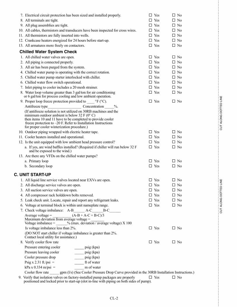
CL-2
- -
- -
- -
- -
- -
- -
- -
- -
- -
- -
- -
- -
- -
- -
- -
- -
- -
- -
- -
- -
- -
- -
- -
- -
- -
- -
- -
- -
- -
- -
- -
- -
- -
- -
- -
- -
- -
- -
- -
- -
- -
- -
- -
- -
- -
- -
- -
- -
- -
- -
- -
- -
- -
- -
- -
- -
- -
- -
- -
- -
- -
- -
- -
- -
- -
- -
- -
- -
- -
- -
- -
- -
- -
- -
- -
- -
- -
- -
- -
- -
- -
- -
- -
- -
- -
- -
- --
- -
- -
- -
- -
- -
- -
- -
- -
- -
-
CU
T A
LON
G D
OT
TE
D L
INE
CU
T A
LON
G D
OT
TE
D L
INE
7. Electrical circuit protection has been sized and installed properly. Yes No8. All terminals are tight. Yes No9. All plug assemblies are tight. Yes No
10. All cables, thermistors and transducers have been inspected for cross wires. Yes No11. All thermistors are fully inserted into wells. Yes No12. Crankcase heaters energized for 24 hours before start-up. Yes No13. All armatures more freely on contactors. Yes No
Chilled Water System Check1. All chilled water valves are open. Yes No2. All piping is connected properly. Yes No3. All air has been purged from the system. Yes No4. Chilled water pump is operating with the correct rotation. Yes No5. Chilled water pump starter interlocked with chiller. Yes No6. Chilled water flow switch operational. Yes No7. Inlet piping to cooler includes a 20 mesh strainer. Yes No8. Water loop volume greater than 3 gal/ton for air conditioning Yes No
or 6 gal/ton for process cooling and low ambient operation.9. Proper loop freeze protection provided to ____ F (C). Yes No
Antifreeze type__________________ Concentration _____%.(If antifreeze solution is not utilized on 30RB machines and the minimum outdoor ambient is below 32 F (0 C) then items 10 and 11 have to be completed to provide cooler freeze protection to –20 F. Refer to Installation Instructions for proper cooler winterization procedure.)
10. Outdoor piping wrapped with electric heater tape. Yes No 11. Cooler heaters installed and operational. Yes No12. Is the unit equipped with low ambient head pressure control? Yes No
a. If yes, are wind baffles installed? (Required if chiller will run below 32 F Yes No and be exposed to the wind.)
13. Are there any VFDs on the chilled water pumps?a. Primary loop Yes Nob. Secondary loop Yes No
C. UNIT START-UP1. All liquid line service valves located near EXVs are open. Yes No2. All discharge service valves are open. Yes No3. All suction service valves are open. Yes No4. All compressor rack holddown bolts removed. Yes No5. Leak check unit. Locate, repair and report any refrigerant leaks. Yes No6. Voltage at terminal block is within unit nameplate range. Yes No7. Check voltage imbalance: A-B______ A-C______B-C______
Average voltage = __________ (A-B + A-C + B-C)/3Maximum deviation from average voltage = _______ Voltage imbalance = ______% (max. deviation / average voltage) X 100Is voltage imbalance less than 2%. Yes No(DO NOT start chiller if voltage imbalance is greater than 2%. Contact local utility for assistance.)
8. Verify cooler flow rate Yes NoPressure entering cooler _____ psig (kpa)Pressure leaving cooler _____ psig (kpa)Cooler pressure drop _____ psig (kpa)Psig x 2.31 ft./psi = _____ ft of waterkPa x 0.334 m/psi = _____ m of waterCooler flow rate _____ gpm (l/s) (See Cooler Pressure Drop Curve provided in the 30RB Installation Instructions.)
9. Verify that isolation valves on factory-installed pump packages are properly Yes No positioned and locked prior to start-up (slot in-line with piping on both sides of pump).
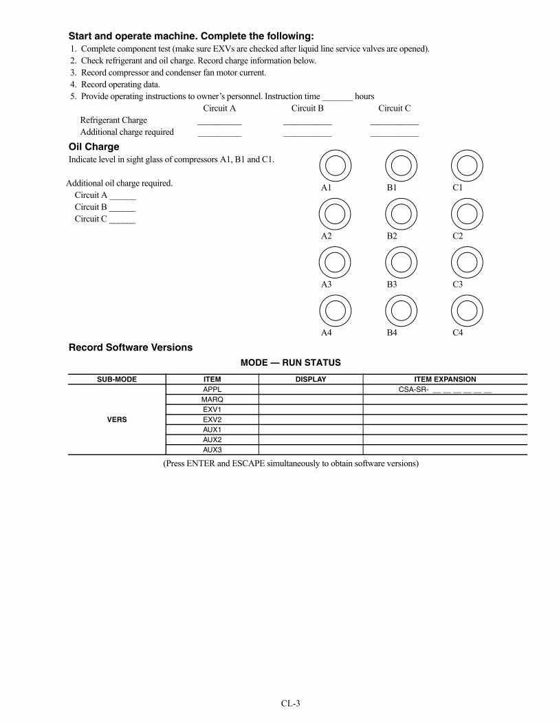
CL-3
Start and operate machine. Complete the following:1. Complete component test (make sure EXVs are checked after liquid line service valves are opened).2. Check refrigerant and oil charge. Record charge information below.3. Record compressor and condenser fan motor current.4. Record operating data. 5. Provide operating instructions to owner’s personnel. Instruction time _______ hours
Circuit A Circuit B Circuit CRefrigerant Charge __________ ___________ ___________Additional charge required __________ ___________ ___________
Oil ChargeIndicate level in sight glass of compressors A1, B1 and C1.
Additional oil charge required. Circuit A ______Circuit B ______Circuit C ______
Record Software VersionsMODE — RUN STATUS
(Press ENTER and ESCAPE simultaneously to obtain software versions)
A1 B1 C1
A2 B2 C2
A3 B3 C3
A4 B4 C4
SUB-MODE ITEM DISPLAY ITEM EXPANSION
VERS
APPL CSA-SR- __ __ __ __ __ __MARQEXV1EXV2AUX1AUX2AUX3

CL-4
- -
- -
- -
- -
- -
- -
- -
- -
- -
- -
- -
- -
- -
- -
- -
- -
- -
- -
- -
- -
- -
- -
- -
- -
- -
- -
- -
- -
- -
- -
- -
- -
- -
- -
- -
- -
- -
- -
- -
- -
- -
- -
- -
- -
- -
- -
- -
- -
- -
- -
- -
- -
- -
- -
- -
- -
- -
- -
- -
- -
- -
- -
- -
- -
- -
- -
- -
- -
- -
- -
- -
- -
- -
- -
- -
- -
- -
- -
- -
- -
- -
- -
- -
- -
- -
- -
- --
- -
- -
- -
- -
- -
- -
- -
- -
- -
-
CU
T A
LON
G D
OT
TE
D L
INE
CU
T A
LON
G D
OT
TE
D L
INE
Record Configuration InformationMODE — CONFIGURATION
SUB-MODE ITEM DISPLAY ITEM EXPANSION ENTRYDISP TEST OFF/ON Test Display LED’s
METR US-METR Metric DisplayLANG x Language
UNIT TYPE x Unit TypeTONS xxx Unit SizeVAR.A x NB Fan on Varifan CIR AVAR.B x NB Fan on Varifan CIR BVAR.C x NB Fan on Varifan CIR CHGBP x Hot Gas Bypass Control60HZ NO/YES 60 Hz FrequencyRECL NO/YES Heat Reclaim SelectEHS x Electric Heater StageEMM NO/YES EMM Module InstalledPAS.E DSBL/ENBL Password EnablePASS xxxx Password Protection Must be DisabledFREE NO/YES Free Cooling SelectPD4.D NO/YES Pro_Dialog Users DisplayBOIL OFF/ON Boiler Command Select
SERV FLUD x Cooler Fluid TypeMOP xx.x EXV MOP SetpointHP.TH xxx.x High Pressure ThresholdSHP.A xx.x Circuit A Superheat SetpSHP.B xx.x Circuit B Superheat SetpSHP.C xx.x Circuit C Superheat SetpHTR xx.x Cooler Heater DT SetpEWTO NO/YES Entering Water ControlAU.SM NO/YES Auto Start When SM LostBOTH NO/YES HSM Both Command SelectLLWT xx Brine Min. Fluid Temp.LOSP xx.x Brine Freeze SetpointHD.PG xx.x Varifan Proportion GainHD.DG xx.x Varifan Derivative GainHD.IG xx.x Varifan Integral GainHR.MI xxx.x Reclaim Water Valve MinHR.MA xxx.x Reclaim Water Valve MaxAVFA NO/YES Attach Drive to Fan AAVFB NO/YES Attach Drive to Fan BAVFC NO/YES Attach Drive to Fan C
OPTN CCNA xxx CCN AddressCCNB xxx CCN Bus NumberBAUD x CCN Baud RateLOAD x Loading Sequence SelectLLCS x Lead/Lag Circuit SelectRL.S ENBL/DSBL Ramp Load SelectDELY xx Minutes Time OffICE.M ENBL/DSBL Ice Mode EnablePUMP x Cooler Pumps SequenceROT.P xxxx Pump Rotation DelayPM.PS NO/YES Periodic Pump StartP.SBY NO/YES Stop Pump in StandbyP.LOC NO/YES Flow Checked if Pump OffLS.ST xx.xx Night Low Noise StartLS.ND xx.xx Night Low Noise EndLS.LT xxx Low Noise Capacity LimOA.TH xx.x Heat Mode OAT ThresholdFREE xx.x Free Cooling OAT LimitBO.TH xx.x Boiler OAT ThresholdEHST xx.xx Elec Stag OAT ThresholdEHSB NO/YES Last Heat Elec BackupE.DEF NO/YES Quick EHS in DefrostEHSP xx Elec Heat PulldownAUTO NO/YES Auto Changeover Select

CL-5
MODE — CONFIGURATION (cont)
MODE — SETPOINT
MODE — OPERATING MODE
SUB-MODE ITEM DISPLAY ITEM EXPANSION ENTRYRSET CRST x Cooling Reset Type
HRST x Heating Reset TypeDMDC x Demand Limit SelectDMMX xx.x mA for 100% Demand LimDMZE xx.x mA for 0% Demand LimitMSSL x Master/Slave SelectSLVA xxx Slave AddressLLBL ENBL/DSBL Lead/Lag Balance SelectLLBD xxx Lead/Lag Balance DeltaLLDY xx Lag Start DelayLAGP x Lag Unit Pump SelectLPUL xx Lead Pulldown Time
SUB-MODE ITEM DISPLAY ITEM EXPANSION ENTRYCOOL CSP.1 xxx.x Cooling Setpoint 1
CSP.2 xxx.x Cooling Setpoint 2CSP.3 xxx.x Ice SetpointCRV1 xx.x Current No Reset ValueCRV2 xx.x Current Full Reset ValueCRT1 xxx.x Delta T No Reset TempCRT2 xxx.x Delta T Full Reset ValueCRO1 xxx.x OAT No Reset TempCRO2 xxx.x OAT Full Reset TempCRS1 xxx.x Space T No Reset TempCRS2 xxx.x Space T Full Reset TempDGRC xx.x Degrees Cool ResetCAUT xx.x Cool Changeover Setpt N/ACRMP x.x Cool Ramp Loading
HEAT HSP.1 xxx.x Heating Setpoint 1 N/AHSP.2 xxx.x Heating Setpoint 2 N/AHRV1 xx.x Current No Reset Val N/AHRV2 xx.x Current Full Reset Val N/AHRT1 xxx.x Delta T No Reset Temp N/AHRT2 xxx.x Delta T Full Reset Temp N/AHRO1 xxx.x OAT No Reset Temp N/AHRO2 xxx.x OAT Full Reset Temp N/ADGRH xx.x Degrees Heat Reset N/AHAUT xx.x Heat Changeover Setpt N/AHRMP x.x Heat Ramp Loading N/A
MISC DLS1 xxx Switch Limit Setpoint 1DLS2 xxx Switch Limit Setpoint 2DLS3 xxx Switch Limit Setpoint 3RSP xxx.x Heat Reclaim Setpoint N/ARDB xx.x Reclaim Deadband N/A
SUB-MODE ITEM DISPLAY ITEM EXPANSION ENTRYSLCT OPER x Operating Control Type
SP.SE x Setpoint SelectHC.SE x Heat Cool SelectRL.SE x Reclaim Select
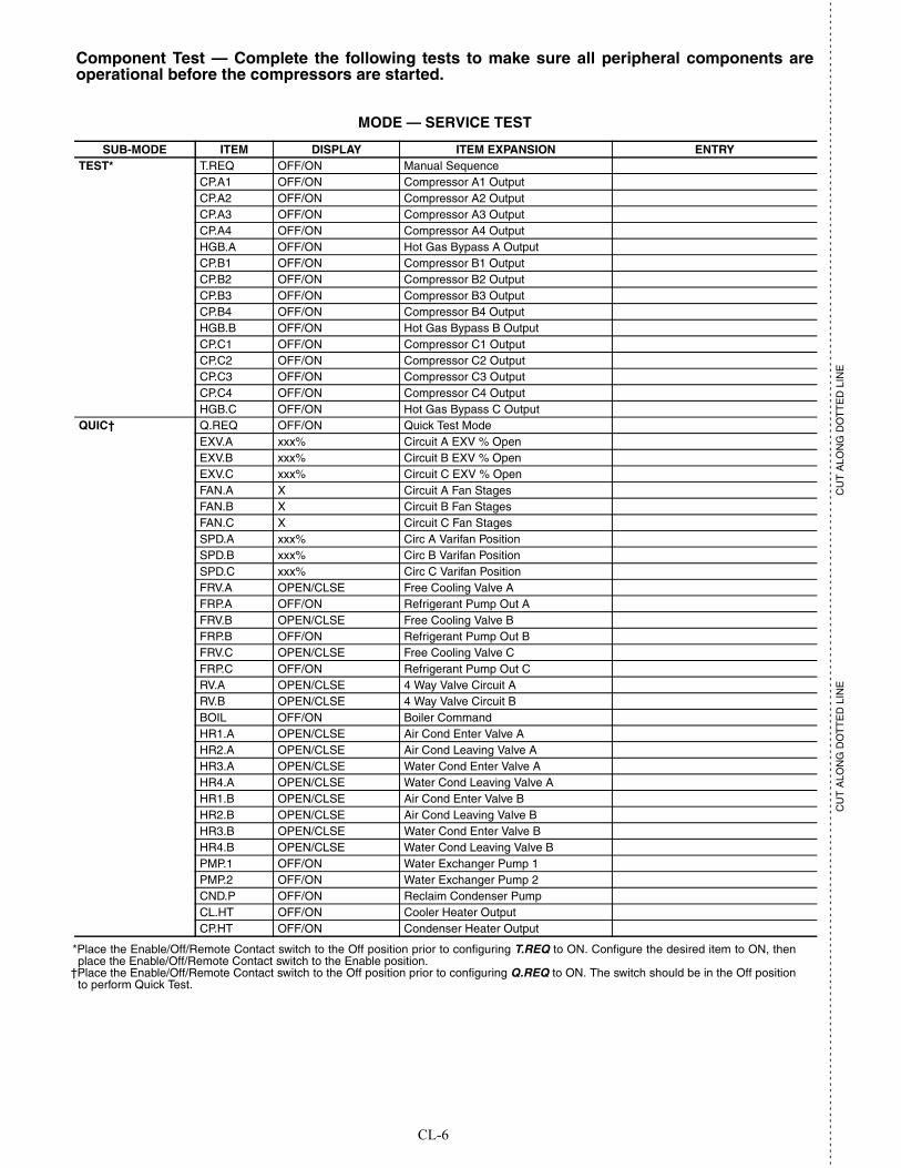
CL-6
- -
- -
- -
- -
- -
- -
- -
- -
- -
- -
- -
- -
- -
- -
- -
- -
- -
- -
- -
- -
- -
- -
- -
- -
- -
- -
- -
- -
- -
- -
- -
- -
- -
- -
- -
- -
- -
- -
- -
- -
- -
- -
- -
- -
- -
- -
- -
- -
- -
- -
- -
- -
- -
- -
- -
- -
- -
- -
- -
- -
- -
- -
- -
- -
- -
- -
- -
- -
- -
- -
- -
- -
- -
- -
- -
- -
- -
- -
- -
- -
- -
- -
- -
- -
- -
- -
- --
- -
- -
- -
- -
- -
- -
- -
- -
- -
-
CU
T A
LON
G D
OT
TE
D L
INE
CU
T A
LON
G D
OT
TE
D L
INE
Component Test — Complete the following tests to make sure all peripheral components areoperational before the compressors are started.
MODE — SERVICE TEST
*Place the Enable/Off/Remote Contact switch to the Off position prior to configuring T.REQ to ON. Configure the desired item to ON, thenplace the Enable/Off/Remote Contact switch to the Enable position.
†Place the Enable/Off/Remote Contact switch to the Off position prior to configuring Q.REQ to ON. The switch should be in the Off positionto perform Quick Test.
SUB-MODE ITEM DISPLAY ITEM EXPANSION ENTRYTEST* T.REQ OFF/ON Manual Sequence
CP.A1 OFF/ON Compressor A1 OutputCP.A2 OFF/ON Compressor A2 OutputCP.A3 OFF/ON Compressor A3 OutputCP.A4 OFF/ON Compressor A4 OutputHGB.A OFF/ON Hot Gas Bypass A OutputCP.B1 OFF/ON Compressor B1 OutputCP.B2 OFF/ON Compressor B2 OutputCP.B3 OFF/ON Compressor B3 OutputCP.B4 OFF/ON Compressor B4 OutputHGB.B OFF/ON Hot Gas Bypass B OutputCP.C1 OFF/ON Compressor C1 OutputCP.C2 OFF/ON Compressor C2 OutputCP.C3 OFF/ON Compressor C3 OutputCP.C4 OFF/ON Compressor C4 OutputHGB.C OFF/ON Hot Gas Bypass C Output
QUIC† Q.REQ OFF/ON Quick Test ModeEXV.A xxx% Circuit A EXV % OpenEXV.B xxx% Circuit B EXV % OpenEXV.C xxx% Circuit C EXV % OpenFAN.A X Circuit A Fan StagesFAN.B X Circuit B Fan StagesFAN.C X Circuit C Fan StagesSPD.A xxx% Circ A Varifan PositionSPD.B xxx% Circ B Varifan PositionSPD.C xxx% Circ C Varifan PositionFRV.A OPEN/CLSE Free Cooling Valve AFRP.A OFF/ON Refrigerant Pump Out AFRV.B OPEN/CLSE Free Cooling Valve BFRP.B OFF/ON Refrigerant Pump Out BFRV.C OPEN/CLSE Free Cooling Valve CFRP.C OFF/ON Refrigerant Pump Out CRV.A OPEN/CLSE 4 Way Valve Circuit ARV.B OPEN/CLSE 4 Way Valve Circuit BBOIL OFF/ON Boiler CommandHR1.A OPEN/CLSE Air Cond Enter Valve AHR2.A OPEN/CLSE Air Cond Leaving Valve AHR3.A OPEN/CLSE Water Cond Enter Valve AHR4.A OPEN/CLSE Water Cond Leaving Valve AHR1.B OPEN/CLSE Air Cond Enter Valve BHR2.B OPEN/CLSE Air Cond Leaving Valve BHR3.B OPEN/CLSE Water Cond Enter Valve BHR4.B OPEN/CLSE Water Cond Leaving Valve BPMP.1 OFF/ON Water Exchanger Pump 1PMP.2 OFF/ON Water Exchanger Pump 2CND.P OFF/ON Reclaim Condenser PumpCL.HT OFF/ON Cooler Heater OutputCP.HT OFF/ON Condenser Heater Output

CL-7
MODE — SERVICE TEST (cont)
*Place the Enable/Off/Remote Contact switch to the Off position prior to configuring T.REQ to ON. Configure the desired item to ON, thenplace the Enable/Off/Remote Contact switch to the Enable position.
†Place the Enable/Off/Remote Contact switch to the Off position prior to configuring Q.REQ to ON. The switch should be in the Off positionto perform Quick Test.
SUB-MODE ITEM DISPLAY ITEM EXPANSION ENTRYQUIC†(cont) CH.A1 OFF/ON Compressor A1 Heater
CH.A2 OFF/ON Compressor A2 HeaterCH.A3 OFF/ON Compressor A3 HeaterCH.A4 OFF/ON Compressor A4 HeaterCH.B1 OFF/ON Compressor B1 HeaterCH.B2 OFF/ON Compressor B2 HeaterCH.B3 OFF/ON Compressor B3 HeaterCH.B4 OFF/ON Compressor B4 HeaterCH.C1 OFF/ON Compressor C1 HeaterCH.C2 OFF/ON Compressor C2 HeaterCH.C3 OFF/ON Compressor C3 HeaterCH.C4 OFF/ON Compressor C4 HeaterHGB.A OFF/ON Hot Gas Bypass A OutputHGB.B OFF/ON Hot Gas Bypass B OutputHGB.C OFF/ON Hot Gas Bypass C OutputQ.RDY OFF/ON Chiller Ready StatusQ.RUN OFF/ON Chiller Running StatusSHUT OFF/ON Customer Shut Down StatCATO xx.x Chiller Capacity 0-10vALRM OFF/ON Alarm RelayALRT OFF/ON Alert RelayC.ALM OFF/ON Critical Alarm Relay

CL-8
- -
- -
- -
- -
- -
- -
- -
- -
- -
- -
- -
- -
- -
- -
- -
- -
- -
- -
- -
- -
- -
- -
- -
- -
- -
- -
- -
- -
- -
- -
- -
- -
- -
- -
- -
- -
- -
- -
- -
- -
- -
- -
- -
- -
- -
- -
- -
- -
- -
- -
- -
- -
- -
- -
- -
- -
- -
- -
- -
- -
- -
- -
- -
- -
- -
- -
- -
- -
- -
- -
- -
- -
- -
- -
- -
- -
- -
- -
- -
- -
- -
- -
- -
- -
- -
- -
- --
- -
- -
- -
- -
- -
- -
- -
- -
- -
-
CU
T A
LON
G D
OT
TE
D L
INE
CU
T A
LON
G D
OT
TE
D L
INE
Operating Data:Record the following information from the Run Status, Temperatures and Outputs Modes when machine is in a stable operating condition. If cooling load is insufficient, these readings must be obtained by putting the chiller intest mode (Service Test) and running each compressor.TEMPERATURESCOOLER ENTERING FLUID EWT _______________COOLER LEAVING FLUID LWT _______________CONTROL POINT CTPT _______________CAPACITY CAP _______________OUTSIDE AIR TEMPERATURE OAT _______________LEAD/LAG LEAVING FLUID CHWS_______________ (Dual Chiller Control Only)OPTIONAL HEAT RECLAIM ENTERING WATER TEMPERATURE HEWT _______________ LEAVING WATER TEMPERATURE HLWT _______________
Install a manifold gage set to obtain readings and verify these against pressure transducers. CIRCUIT A CIRCUIT B CIRCUIT C SCT.A __________ SCT.B __________ SCT.C___________SST.A __________ SST.B __________ SST.C ___________SGT.A __________ SGT.B __________ SGT.C ___________SUP.A __________ SUP.B __________ SUP.C ___________EXV.A__________ EXV.B __________ EXV.C ___________ NOTE: EXV A,B,C positions are found in the output mode.
COMPRESSOR MOTOR CURRENTL1 L2 L3
COMPRESSOR A1 ______ ______ ______COMPRESSOR A2 ______ ______ ______COMPRESSOR A3 ______ ______ ______COMPRESSOR A4 ______ ______ ______COMPRESSOR B1 ______ ______ ______COMPRESSOR B2 ______ ______ ______COMPRESSOR B3 ______ ______ ______COMPRESSOR B4 ______ ______ ______COMPRESSOR C1 ______ ______ ______COMPRESSOR C2 ______ ______ ______COMPRESSOR C3 ______ ______ ______COMPRESSOR C4 ______ ______ ______
CONDENSER FAN MOTOR CURRENTL1 L2 L3
FAN MOTOR 1 ______ ______ ______FAN MOTOR 2 ______ ______ ______FAN MOTOR 3 ______ ______ ______FAN MOTOR 4 ______ ______ ______FAN MOTOR 5 ______ ______ ______FAN MOTOR 6 ______ ______ ______FAN MOTOR 7 ______ ______ ______FAN MOTOR 8 ______ ______ ______FAN MOTOR 9 ______ ______ ______
L1 L2 L3FAN MOTOR 10 ______ ______ ______FAN MOTOR 11 ______ ______ ______FAN MOTOR 12 ______ ______ ______FAN MOTOR 13 ______ ______ ______FAN MOTOR 14 ______ ______ ______FAN MOTOR 15 ______ ______ ______FAN MOTOR 16 ______ ______ ______FAN MOTOR 17 ______ ______ ______FAN MOTOR 18 ______ ______ ______
CL-9
COMMENTS:________________________________________________________________________________________________________________________________________________________________________________________________________________________________________________________________________________________________________________________________________________________________________________________________________________________________________________________________________________________________________________________________________________________________________________________________________________________________________________________________________________________________________________________________________________________________________________________________________________________________________________________________________________________________________________________________________________________________________________________________________________________________________________________________________________________________________________________________________________________________________________________________________________________________________________________________________________________________________________________________________________________________________________________________________________________________________________________________________________________________________________________________________________________________________________________________________________________________________________________________________________________________________________________________________________________________________________________________________________________________________________________________________________________________________________________________________________
SIGNATURES:Start-upTechnician _____________________________________ Date______________________________________________
CustomerRepresentative __________________________________ Date______________________________________________
Manufacturer reserves the right to discontinue, or change at any time, specifications or designs without notice and without incurring obligations.Catalog No. 04-53300028-01 Printed in U.S.A. Form 30RB-3T Pg CL-10 12-09 Replaces: 30RB-2T
Copyright 2009 Carrier Corporation
- -
- -
- -
- -
- -
- -
- -
- -
- -
- -
- -
- -
- -
- -
- -
- -
- -
- -
- -
- -
- -
- -
- -
- -
- -
- -
- -
- -
- -
- -
- -
- -
- -
- -
- -
- -
- -
- -
- -
- -
- -
- -
- -
- -
- -
- -
- -
- -
- -
- -
- -
- -
- -
- -
- -
- -
- -
- -
- -
- -
- -
- -
- -
- -
- -
- -
- -
- -
- -
- -
- -
- -
- -
- -
- -
- -
- -
- -
- -
- -
- -
- -
- -
- -
- -
- -
- --
- -
- -
- -
- -
- -
- -
- -
- -
- -
-
CU
T A
LON
G D
OT
TE
D L
INE
CU
T A
LON
G D
OT
TE
D L
INE