330900 site utilities metering - university of florida
TRANSCRIPT

June 2021 330900 Site Utilities Metering UF Design and Construction Standards Page 1 of 23
330900 Site Utilities Metering Sections Included In This Standard: 1.0 GENERAL ……………………………………………………………………………………………..1 2.0 TEMPORARY UTILITIES SERVICE CONNECTIONS AND METERING ………………………2 3.0 ELECTRICAL METERS ……………………………………………………………………………...3 4.0 WATER METERING …………………………………………………………………………….…..10 5.0 CHILLED WATER, STEAM AND STEAM CONDENSATE ………………………………......15 6.0 NATURAL GAS METERING..…………………………………………………………………….23
1.0 GENERAL
A: This standard is for Metering of Utilities only. It does not cover sub metering for Building
Automation System monitoring or for Power Quality Metering (VERIS, SATEC etc.).
B: Connection to any UF Utilities (Water/Electric/Steam/Chilled water etc...) without approval and /or unmetered is strictly prohibited. This will result in disconnection and delay in work with potential fines. NO EXCEPTIONS!
C: If you are not already a Facilities Services customer with an account number, a Request
for a Customer Application Form and set-up billing account with Facilities Services. Call Facilities Services Billing (352) 392-4030 to have a copy faxed to you.
D: For deviations from this standard a deviation request must be submitted via the process
on the standards web site. Approval will be made in writing by the Facilities Services Utilities Meter Dept.
E: The project must plan for a 6 to 8 weeks lead time for delivery of metering equipment. The
Utilities Metering Department does not have spare equipment for the project to borrow while new equipment is being delivered.
F: All Utility Service Meters must be installed per manufacturer’s recommendations.
G: Meters shall be located downstream of Utility Service Disconnect / Valve and upstream of
building isolation disconnect / valve on supply mains.
H: All Meter Installations must pass Utility Services Department Inspection and capable of measuring flow / totals prior to service activation.
I: Installations with inadequate straight pipe runs are not allowed. The Project Engineer
shall design all metering system components such that they for in the space provided. J: If a project impacts a Utility (changes utility size, moves utility including meter, etc.) the
project needs to bring that Utility meter up to standard. Some examples of this would be…
1: Part of the Domestic water line, not including meter, needs to be relocated due
to the project. The project then would not need to install a new water meter, assuming the project is not changing anything besides location.
2: The building renovations require a larger transformer. The project then would follow the standard for a new electric meter and be responsible for the new meter.

June 2021 330900 Site Utilities Metering UF Design and Construction Standards Page 2 of 23
2.0 TEMPORARY UTILITIES SERVICE CONNECTIONS AND METERING
A: REQUESTING TEMPORARY CONNECTION TO WATER/ELECTRIC/STEAM/CHILLED WATER etc... 1: Place work order https://www.facilitiesservices.ufl.edu/facility-maintenance-and-
project-request/ to appropriate Dept. 2.A.1.a: Temp Water: Water Distribution (Note: If using domestic water that has
existing water meter place work order to Facilities Services Utilities) 2.A.1.b: Temp Electric Power: Electrical Distribution
B: REQUESTING TEMPORARY ELECTRICAL CONNECTION.
1: PLEASE NOTE: Any remodeling/renovation project that requires Temp Power for contractor’s trailers onsite it is Mandatory that Facilities Services Utilities Department shall be contacted for requirements for metering, no other entity shall decide or grant if meter is required!
2: After designated site requirements have been determined for service voltage needs and site location for temporary power agreed upon with Facilities Services Electric Distribution team, contact: Facilities Services Work Management (352 392-1121 or [email protected]) to be put in touch with the Facilities Services Electric Meter Technician: Harry Walko, Work: (352) 294-0606 Mobile: (386) 266-8643 E-mail: [email protected] or Utilities at (352)294-0708. Please be prepared to provide information: Type service being provided - service voltage, single phase, two or three phase, 2, 3, 4-wire Y or Δ, expected connected load and panel rating.
3: Temporary Electric Meters and Accessories. 2.B.3.a: All accessories: (CTs, compatible meter socket/can) are CFCI
(Contractor-Furnished, Contractor-Installed) and to be designated exclusively by Facilities Services Meter Dept. prior to installation of any electric metering equipment on site.
2.B.3.b: Electric Meter: OFCI (Owner-Furnished, Contractor-Installed) All Temporary electric meters are furnished by Facilities Services Meter Department. Temp Electrical meter to be returned after deactivation from service to Facilities Services Meter Department. Contractor supplied temporary electric meters are strictly prohibited.
2.B.3.c: After meter equipment has been installed by Contractor:
2.B.3.c.i: Mandatory Inspections: All connections to electric service for temporary power require inspections from EH&S and Facilities Services even if electric meter is not installed. No exceptions!
2.B.3.c.ii: No connection to power can be energized without prior
inspections completed and passed after inspections have been completed and passed prior to energizing Facilities Services Meter Dept. will provide the temporary electric meter.
2.B.3.c.iii: (Failure to comply with both inspections will cause site not to be energized till completed)
2.B.3.d: If needing outage to terminate conductors to energize service:
2.B.3.d.i: Utility Outage Request Form must be submitted to Facilities Services WMC prior to outage. The number of days is a function of the scope of the outage. Request outage thru

June 2021 330900 Site Utilities Metering UF Design and Construction Standards Page 3 of 23
link provided: https://www.facilitiesservices.ufl.edu/_library/UtilityOutagesRequestForm.pdf
2.B.3.d.ii: Submit Utility Outage Request thru Facilities Services Work Management with the understanding that you will need to call for inspections from EH&S and Facilities Services prior to energizing. For best results request inspections to be done same day/time once both inspections have passed service will be energized.
2.B.3.e: If not requiring an outage to energize:
2.B.3.e.i: Skip utility outage request and request the two inspections EH&S and Facilities Services.
3.0 ELECTRICAL METERS A: Revenue Watt-hour meters shall meet the following requirements: B: General
1: All projects Major/Minor or any new/existing connections to UF electrical utilities shall have ELSTER/BYRAM LAB.S electric revenue watt-hour meters. These meters shall have built-in 900 MHz RF (radio frequency) communication configured into the UF CAMPUS AMR system (automated meter reading) the system service is provided through BYRAM LABORATORIES and shall be installed to capture entire building or structure electrical watt-hour consumption for UF revenue billing.
3.B.1.a: Electrical watt-hour metering shall be metered from building transformer
on the secondary side whenever possible for revenue metering, if current transformers are required they are to be placed over the bushings (secondary spades) on secondary side of transformer unless prior authorization is obtained from Facilities Services Utilities Meter Dept.
3.B.1.b: If building has space or area occupied by entity/occupant other than building owner and requires separate utilities billing i.e. Food Court or Vendor areas meter shall be ELSTER/BYRAM LAB.S electric watt-hour meters.
3.B.1.c: Electric meter and all accessories (CTs, compatible meter socket/can
etc.) are CFCI (Contractor-Furnished, Contractor-Installed).
2: For all major and minor renovation projects with intent of using existing electrical service and metering equipment. i.e. if an existing building is demolished and new building is to replace it using existing electrical service feed and metering equipment, if requiring terminations inside pad-mount transformers or at overhead transformers or if metered inside at service entrance or gear and terminations are made. 3.B.2.a: All existing metering equipment, meter enclosure, CT’s etc… must be
upgraded CFCI (Contractor-Furnished, Contractor-Installed) to meet current Facilities Services Utilities Meter Dept. requirement for metering equipment.

June 2021 330900 Site Utilities Metering UF Design and Construction Standards Page 4 of 23
3.B.2.b: Facilities Services Utilities Meter Dept. shall be presented electrical drawing details for recommendations and approval failure to comply will result in contractor responsible for upgrading to current Facilities Services Utilities Meter Dept. standards for electrical metering.
3.B.2.c: Note: existing revenue kWh electrical meters can be re-used (meter
only) depending if service voltage does not change and ampacity does not exceed current meter requirements, but all existing metering equipment CT’s, PT’s, meter enclosure & socket and all wiring will be required to be replaced meeting current Facilities Services Utilities Meter Dept. requirements for metering.
3: All Revenue kWh meters Transformer rated or Self-Contained (Feed-Thru) shall
be:
3.B.3.a: TYPE: A3TL RF (Radio Frequency) Node meters these meters shall have built-in 900 MHz RF. (Meters are socket style meters unless otherwise specified by Facilities Services Meter Dept. not to be confused with SATEC, SHARK etc…)
3.B.3.a.i: Accepted Manufacturer: ELSTER/BYRAM LAB.S , NO
OTHERS ACCEPTED
4: Electrical drawings shall provide a wiring diagram for meter installations including all devices used in the metering circuit and submitted to Facilities Services Utilities Meter Dept. for approval no later than 60% review.
5: All ELSTER/BYRAM LAB. Electric meters are property of Facility Services Utility
Meter Dept. any/all disconnected from service Facility Services Utility Meter Dept. shall be contacted and any/all removed from service shall be returned to Facility Services Meter Dept.
6: All pad mount transformer installations for revenue metering will require 1” RNC
conduit from meter enclosure to electrical room for future network cable unless otherwise specified by Facilities Services Utilities Meter Dept.
7: All meters and associated metering equipment (meter socket/enclosure, CT
cabinets, CT's etc.....) shall be grounded and bonded in accordance with NEC requirements.
8: Meter installations inspections are mandatory by Facilities Services Utilities
Meter Dept. for compliance with these specifications prior to submitting request for energizing. Any discrepancies shall be noted to the Constructor for action and a re-inspection shall be required prior to UF Utility Services turning on power.
C: Transformer Rated Meters:
1: Meter Type: A3TL RF (radio frequency) Node meters these meters shall have built-in 900 MHz RF
3.C.1.a: Accepted Manufacturer: ELSTER/BYRAM LABS, NO OTHER’S
ACCEPTED
2: Transformer rated meters shall be: FORM 9S/CLASS 20 for all 3ph 4W
June 2021 330900 Site Utilities Metering UF Design and Construction Standards Page 5 of 23
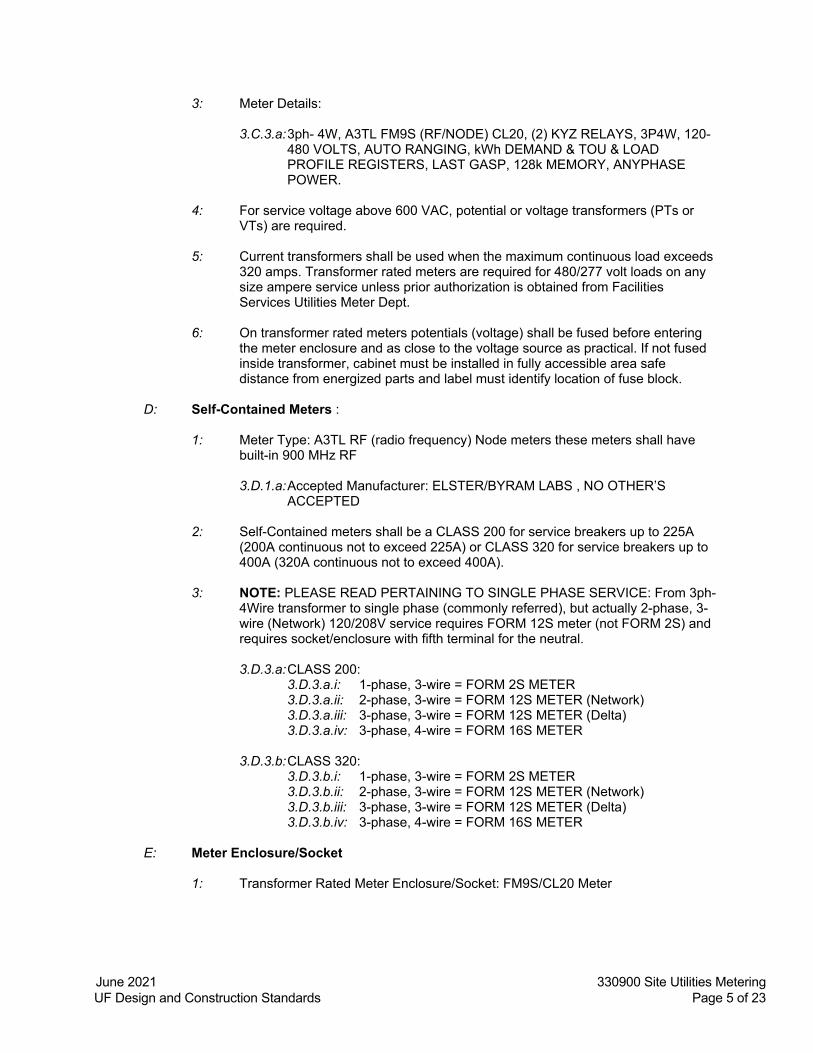
3: Meter Details:
3.C.3.a: 3ph- 4W, A3TL FM9S (RF/NODE) CL20, (2) KYZ RELAYS, 3P4W, 120-480 VOLTS, AUTO RANGING, kWh DEMAND & TOU & LOAD PROFILE REGISTERS, LAST GASP, 128k MEMORY, ANYPHASE POWER.
4: For service voltage above 600 VAC, potential or voltage transformers (PTs or
VTs) are required.
5: Current transformers shall be used when the maximum continuous load exceeds 320 amps. Transformer rated meters are required for 480/277 volt loads on any size ampere service unless prior authorization is obtained from Facilities Services Utilities Meter Dept.
6: On transformer rated meters potentials (voltage) shall be fused before entering
the meter enclosure and as close to the voltage source as practical. If not fused inside transformer, cabinet must be installed in fully accessible area safe distance from energized parts and label must identify location of fuse block.
D: Self-Contained Meters :
1: Meter Type: A3TL RF (radio frequency) Node meters these meters shall have built-in 900 MHz RF
3.D.1.a: Accepted Manufacturer: ELSTER/BYRAM LABS , NO OTHER’S
ACCEPTED
2: Self-Contained meters shall be a CLASS 200 for service breakers up to 225A (200A continuous not to exceed 225A) or CLASS 320 for service breakers up to 400A (320A continuous not to exceed 400A).
3: NOTE: PLEASE READ PERTAINING TO SINGLE PHASE SERVICE: From 3ph-
4Wire transformer to single phase (commonly referred), but actually 2-phase, 3- wire (Network) 120/208V service requires FORM 12S meter (not FORM 2S) and requires socket/enclosure with fifth terminal for the neutral.
3.D.3.a: CLASS 200:
3.D.3.a.i: 1-phase, 3-wire = FORM 2S METER 3.D.3.a.ii: 2-phase, 3-wire = FORM 12S METER (Network) 3.D.3.a.iii: 3-phase, 3-wire = FORM 12S METER (Delta) 3.D.3.a.iv: 3-phase, 4-wire = FORM 16S METER
3.D.3.b: CLASS 320: 3.D.3.b.i: 1-phase, 3-wire = FORM 2S METER 3.D.3.b.ii: 2-phase, 3-wire = FORM 12S METER (Network) 3.D.3.b.iii: 3-phase, 3-wire = FORM 12S METER (Delta) 3.D.3.b.iv: 3-phase, 4-wire = FORM 16S METER
E: Meter Enclosure/Socket
1: Transformer Rated Meter Enclosure/Socket: FM9S/CL20 Meter

June 2021 330900 Site Utilities Metering UF Design and Construction Standards Page 6 of 23
2: Phase, 4 Wire “Y” or “Delta” Transformer rated meters and meter sockets shall be 13 terminal type and shall have a 10 pole potential and CT circuit closing test switch (Specify service voltage when ordering)
3: When ordering enclosure specify NO. 602-3040B13-311
4: Test Switch Arrangement for meter enclosure specify No. 110-54583
5: Accepted Manufacturer: Meter Devices Co. /BYRAM LABS , NO OTHER’S
ACCEPTED
6: Self-Contained Meter Enclosure/Socket: All self-contained meter enclosures require lever by-pass with jaw-tension release, rated for appropriate amperage.
7: Three phase, 4 wire Delta for 120/240V services shall have the B phase or "high
leg" marked orange, high-leg conductor (208V to neutral) to terminate on the “C” (right) phase of the meter socket enclosure.
F: Wiring
1: Current transformer wiring and potential wiring shall be color-coded respectively: 3.F.1.a: Service voltages of 208/120 shall be Black for “A” phase; Red for “B”
phase and Blue for “C” phase, Neutral White - Ground ”green”.
3.F.1.b: Service voltages of 480/277 shall be Brown for “A” phase; Orange for “B” phase and Yellow for “C” phase, Neutral Gray – Ground “green with yellow stripe”.
2: Potential wiring on transformer rated circuits shall be #12 AWG copper THHN -
stranded at all times to distinguish from the current.
3: Current transformer wiring shall be a size #10 AWG copper THHN- stranded.
4: Current transformers shall have dedicated neutrals color coded for phase using phase tape.
5: All stranded wire requires crimped ringed connectors. (Except CT Shorting Block
Designed for Wires to be Inserted) G: Current Transformers
1: Current Transformers will be AccuRange High Accuracy extended range current Transformers and meet the IEEE 0.15S accuracy class of 0.15% from 5% of nominal current through rating factor.
2: H1 SIDE OF CT WILL FACE LINE SIDE OF SERVICE
3: Accepted Manufacturer: ABB
H: Current Transformer Cabinet
1: Cabinet Size Must Conform to Current NEC Requirements 2: Must meet NEMA Type 3R - UL 50 Type 3R standards
June 2021 330900 Site Utilities Metering UF Design and Construction Standards Page 7 of 23
3: ANSI 61 gray finish
4: Enclosure and cover manufactured from 16 or 14 gauge G90 galvanized Steel.
5: Doors overlapping with no center post.
6: Three point pad-lockable handle or pad- lockable draw latch.
7: Shall have separate steel back plate or brackets suitable for bolted mounting of
CT’s.
8: Wood back plate for CT mounting is prohibited.
9: The C.T’s shall be securely attached to either a backing plate or brackets that are mounted to the back of the C.T. cabinet with mounting studs that are permanently attached to the cabinet. Attaching the C.T.’s through the back of the cabinet to the wall is not acceptable. (Steel back plate or brackets will need to be ordered as optional item.)
10: The CT cabinet, meter socket, and all associated conduits and equipment shall be securely mounted to the building wall using lag bolts, masonry anchors, or similar hardware – plastic anchors are not acceptable.
11: Bottom of cabinet minimum 24 inches from finish floor level and top of cabinet
maximum 7 feet.
12: Center line of meter display should be no more than 6ft.
13: Meter/enclosure should be mounted where fully accessible to personnel.
14: All enclosures shall be grounded and bonded per NEC requirements.
15: Accepted Manufacturer: MILBANK
I: Insulation Piercing Voltage Tap (Insulation Piercing Connector used with CT cabinet
installations)
1: Must Meet: ANSI C119.4, UL 486B Listed
2: Must Terminate To Fuse Block Mounted Inside CT Cabinet
3: (Will need 4 total for 3ph-4w service: 3 for potentials/voltage – 1 for neutral)
3.I.3.a: Conductor Range: Main AWG: 750-3/0 Tap AWG: 10-14
June 2021 330900 Site Utilities Metering UF Design and Construction Standards Page 8 of 23
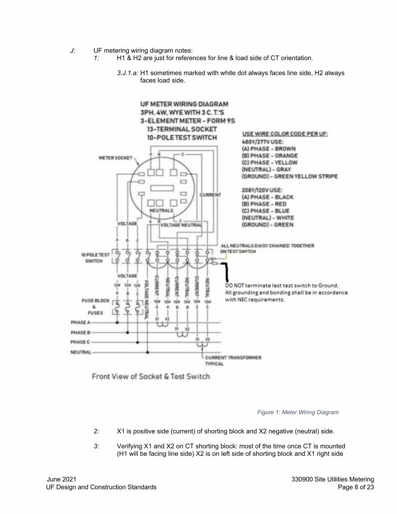
J: UF metering wiring diagram notes: 1: H1 & H2 are just for references for line & load side of CT orientation.
3.J.1.a: H1 sometimes marked with white dot always faces line side, H2 always
faces load side.
2: X1 is positive side (current) of shorting block and X2 negative (neutral) side.
3: Verifying X1 and X2 on CT shorting block: most of the time once CT is mounted (H1 will be facing line side) X2 is on left side of shorting block and X1 right side
Figure 1: Meter Wiring Diagram

June 2021 330900 Site Utilities Metering UF Design and Construction Standards Page 9 of 23
when facing the H2 (load side), X2 lead will terminate to neutral test switch and X1 lead will terminate to current test switch, but this can vary with different CT manufacturers make sure to sync current and neutrals with voltage phases.
4: Unshort shorting block before energizing do not remove the shorting links park
links in the open position.
5: On transformer rated meters potentials (voltage) shall be fused before entering meter enclosure as close to voltage source as practical if not fused inside transformer cabinet must be installed in fully accessible area safe distance from energized parts and label must identify location of fuse block.
6: Current transformers wiring shall be #10 copper, thhn – stranded.
7: Potential (voltage) wiring shall be #12 copper, thhn – stranded.
8: All stranded copper wire shall have crimped ringed connectors with the exception
of CT shorting block, use holes provided on CT shorting block for x1 & x2 terminations.
9: Current transformers shall have dedicated neutrals color coded for phase using
phase tape.
10: All neutrals including voltage neutral shall be daisy chained together on test switch.
Figure 2

June 2021 330900 Site Utilities Metering UF Design and Construction Standards Page 10 of 23
11: Inspection request form for facility services be sure to state electric meter inspection and will not be energized till both parties have inspected and inspections have passed.
4.0 WATER METERING
A: General
1: For 2 inch and above meters each service connection entering building shall be metered inside building mechanical rooms if main riser enters mechanical room and only if meter captures entire domestic water service to building, otherwise will be metered exterior of building capturing entire domestic service to building. (Any or all taps or tie-in’s upstream of main building utilities revenue domestic water meter are strictly prohibited unless separately metered and agreed upon by Facility Services Meter Dept.)
2: If building has space or area occupied by entity other than building owner that will
require separate utilities billing this will require separate revenue water meter installed to capture usage for this space i.e.… Food Court or Vendor areas and shall be required to follow these Standards for Revenue Water Meters or if agreed upon by owner and other entity both parties agreeing can be billed by fixed rate based on load assessment calculations and document signed by owner provided to Facility Services Utilities Department and if not metered separately or virtual agreement owner will be responsible for all utilities.
3: Water meters for domestic water shall be sized by Design Engineer according to
flow rate requirements for system.
4: Water meter and all Metering Dept. requirements (valves, valve boxes, strainer, meter box etc...) are CFCI (Contractor-Furnished, Contractor-Installed).
5: All pipe specifications and type materials to be used for inside building domestic
and outside domestic water shall be per UF Standards.
6: Design drawing shall be submitted to Facilities Services Utilities Meter Dept. for approval no later than 60% plan review.
7: Compound water meters are prohibited unless specified or approved in writing by
Facilities Services Utilities Meter Dept.
8: Water meters shall have Absolute encoder technology (Digital registers not acceptable) shall be PROCODER register or PROREAD (PROREAD are being phased out by NEPTUNE and PROCODER replacing them) all meters shall be compatible with BYRAM LABS. – RF (Radio Frequency) water meter module for remote reading to Automated Meter Infrastructure service provider BYRAM LABS. Water meter shall have replaceable register not requiring entire water meter to be replaced if needing only register replaced.
4.A.8.a: Accepted Manufacturer: NEPTUNE
4.A.8.b: Excluded or Prohibited: NEPTUNE E-CODER R900i which is
proprietary to NEPTUNE AMI only.

June 2021 330900 Site Utilities Metering UF Design and Construction Standards Page 11 of 23
9: All meters shall have remote TOUCH-PADS installed to lids capable being read with Wand on all meters installed METER BOX or PIT (grate or solid plate) mounted to lid by contractor per manufactures instructions and will not be accepted with-out touch-pad mounted on lid. All meters shall be required to read all digits of register with WAND or BYRAMS LABS.RF module. All meters shall have registers rated for outside installation and shall have lid or cover on register to protect register even installed inside building
10: For all major and minor renovation projects with intent of using existing water service connection and water meter, also if an existing building is demolished and new building is to replace it using existing water service connection and water meter It shall be upgraded CFCI (Contractor-Furnished, Contractor-Installed) to meet current UF Standards for water meters. Facilities Services Utilities Meter Dept. should be notified and presented drawing details for domestic water service connections for recommendations and approval. Failure to comply will result in contractor responsible for upgrading to current Facilities Services Utilities Meter Dept. standards for water meters.
11: Water Meter (ATTENTION: Register must be compatible with BYRAM LABS
Radio Frequency Module)
12: All water meters installed on potable water shall meet the requirements of the manufacturer.
13: Meters are to be installed where fully accessible to read register, meters installed
inside buildings are not to be mounted over other equipment such as air handlers etc… or mounted overhead causing metering personnel to climb ladder to read register, should not be installed more than 5-ft above finish floor level and easily accessible to all components (meter, valves, strainer etc…) including reading of the meter register.
14: Meters shall measure in gallons.
15: All water meters shall be installed with strainer at the meter inlet, strainer shall be
of the same size and manufacturer as the meter. Strainers prevent debris from entering the meter and corrects the velocity profile of the flow to the meter and reduces the effects of upstream piping variations or other obstructions in the line.
16: When installing Neptune meters with a strainer, a minimum of four pipe
diameters of straight run pipe (can include components that are fully open in their normal operating position) is required upstream and two to four diameters of straight run pipe downstream of the meter and strainer assembly.
4.A.16.a: Strainer Accepted Manufacturer: NEPTUNE
17: If there is not enough pipe diameters of straight run to fit a strainer in, this
deviation need sto be approved by Facilites Services Utilities Meter Department in writting.
18: Note: Turbine meters must operate in a completely filled line at all times. The downstream piping must always provide sufficient back pressure to maintain a full line at the meter. It is important that the upstream inlet-side valve is put in the full-open position during service. A partially throttled upstream valve can cause flow profile distortion that can adversely affect meter accuracy. All throttling should be done only on the downstream outlet-side of the meter.
June 2021 330900 Site Utilities Metering UF Design and Construction Standards Page 12 of 23
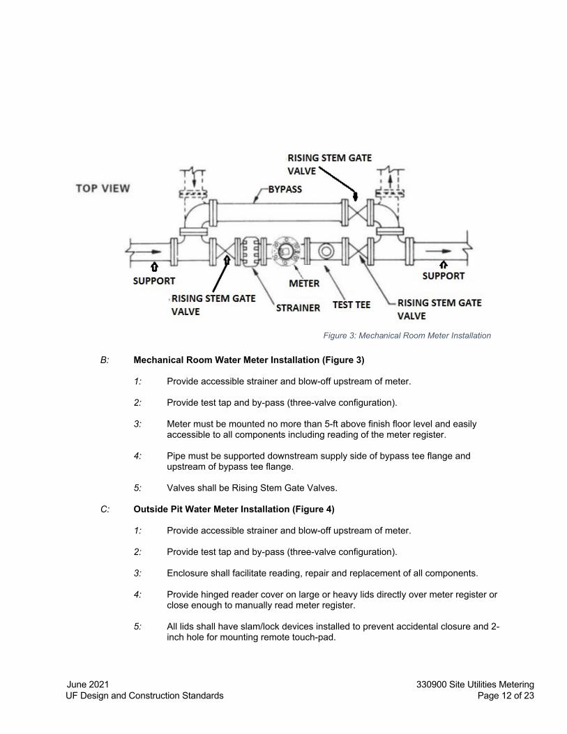
B: Mechanical Room Water Meter Installation (Figure 3)
1: Provide accessible strainer and blow-off upstream of meter.
2: Provide test tap and by-pass (three-valve configuration).
3: Meter must be mounted no more than 5-ft above finish floor level and easily accessible to all components including reading of the meter register.
4: Pipe must be supported downstream supply side of bypass tee flange and
upstream of bypass tee flange.
5: Valves shall be Rising Stem Gate Valves.
C: Outside Pit Water Meter Installation (Figure 4)
1: Provide accessible strainer and blow-off upstream of meter.
2: Provide test tap and by-pass (three-valve configuration).
3: Enclosure shall facilitate reading, repair and replacement of all components.
4: Provide hinged reader cover on large or heavy lids directly over meter register or close enough to manually read meter register.
5: All lids shall have slam/lock devices installed to prevent accidental closure and 2-
inch hole for mounting remote touch-pad.
Figure 3: Mechanical Room Meter Installation

June 2021 330900 Site Utilities Metering UF Design and Construction Standards Page 13 of 23
6: Install exterior to building, with enclosure flush to grade. Meter shall not be more than thirty inches (30") below grade.
7: Valves shall be Rising Stem Gate Valves
8: The enclosure shall be constructed of cast iron, pre-cast reinforced concrete, or CMU with reinforcing and cells poured solid (polycarbonate boxes are not acceptable).
9: Enclosure cover shall be traffic rated load bearing.
D: Meter Box Water Meter Installation (Figure 5 and 6)
1: Provide by-pass (three-valve configuration)
2: Valves shall be Square Head Gate valves, Ball valves are not to be used.
3: Enclosure mounted flush to grade in area not prone to flooding.
4: Enclosure shall meet or exceed ANSI/SCTE-77 Tier 8 rating used in non-vehicular traffic situations only, if enclosure mounted in sidewalk next to a curb where there is an increased likelihood of coming into contact with vehicles ANSI/SCTE-77 Tier 15 rating or above enclosure shall be used.
5: Covers shall be flush mount heavy duty rated with AMR recess (2” hole which
also allows mounting of remote read touch-pad) to be mounted as part of installation.
4.D.5.a: Cover shall have a Hinged Reader Cover
Figure 4: Exterior Pit Room Water Meter Installation

June 2021 330900 Site Utilities Metering UF Design and Construction Standards Page 14 of 23
6: Valve box shall be cast iron, surround with concrete pad chamfered edges.
7: All valves installed 12 inches minimum from outside edge of meter box to allow
for concrete pad around valve box
Figure 6: Valve Box Detail
Figure 5: Meter Box Installation

June 2021 330900 Site Utilities Metering UF Design and Construction Standards Page 15 of 23
5.0 CHILLED WATER, STEAM AND STEAM CONDENSATE
A: General
1: Steam and Condensate Meters shall be piped with service bypass around the
meter. Applies to water as well, check
2: Steam Meters shall be located in piping upstream of PRV (pressure reducing valve) and sized per service pressure (typical 65-70 psig).
3: All sensors /transducers shall be appropriately selected to most closely match
the expected sensing range. If, upon startup and balancing, a sensor/transducer is operating below 20% or above 80% of its sensing range, the sensor/transducer shall be replaced at no additional cost with an appropriate range such that the measured value (operating at normal conditions) is between 30% and 70% of the sensor/transducer range.
B: Chilled Water, Steam, & Condensate Utility Meters with BTU Flow Computers:
1: All Utility Flow Computers / Totalizers:
5.B.1.a: Must be interconnected via BACnet® MS/TP in to Utility Services
BACnet® IP / MS/TP Router (NOT TO BE WIRED INTO BAS SYSTEMS). Utility Services shall provide BACnet® IP / MS/TP Interface Cabinet, Enclosure, Each Chilled Water Meter Installation will require Chilled water supply and return PSIG (4-20mA signal), Steam Meter Installations will require Pressure Transmitter (4-20mA signal) and Identify specific Location per installation. All BACnet® IDs must be obtained from Utility Services Department. Flow computers must accept 24Vac power source voltage via stepdown transformer. All meter / flow computer wiring must meet manufactures requirements for number of conductors and grounding. Please contact Utility Services Department (352) 294-0708 for further information.
5.B.1.b: The entire metering system shall be built and calibrated by a single manufacturer, ONICON Incorporated, and shall consist of a flow meter, two matched temperature sensors, a Btu (tonnage) [chilled water] / (LBSM) [steam] / (Total Gallons) [Condensate] calculator, temperature thermo-wells, and all required mechanical installation hardware. A certificate of NIST* traceable calibration (Submitted to Utility Services Department Bldg. #0702 Suite 130) shall be provided with each system. All equipment shall be covered by the manufacturer’s two year warranty.
C: Flow/BTU Meter General:
1: Refer to the following flow meter sections for specific flow meter requirements.
The flow meter shall be installed in the supply pipe of the system to be measured following the manufacturer’s instructions with particular attention to upstream and downstream straight pipe runs. Pipe runs are critical regarding accuracies. Pipe
June 2021 330900 Site Utilities Metering UF Design and Construction Standards Page 16 of 23
location measurements (upstream / downstream) must be submitted to Utility Services Department per installation.
2: Hot water shall not be metered as an exception to steam metering for utility metering purposes. Exceptions: when adequate pipe runs cannot be met Engineer must receive written approval from Utility Services chilled water and steam metering department prior to placing any orders for meters.
3: Btu Meter: Provide an ONICON System-10 Btu Meter: The Btu meter shall
provide the following points both at the integral LCD and as BACnet® communication:
5.C.3.a: Chilled Water Metering Points / Units: Energy Total [ton x 1], Energy
Rate [tonh x 1], Flow Rate (GPM x 1), Flow Total (Gal x 1) Supply Temperature (DEGF) and Return Temperature (DEGF).
5.C.3.b: Steam Metering Points Provide an ONICON D-100 Btu Meter : Volume Total [lbm x 1], Volume Rate [lbm/h x 1].
5.C.3.c: Condensate Metering Points Provide an Onicon D-100 Btu Meter: Volume Total (Total GAL x 1), Volume Rate (GPM x 1).
5.C.3.d: Additional Points / Transmitters: Chilled Water Supply PSIG: [4-20mA],
Chilled Water Return PSIG [4-20mA], Steam PSIG: [4-20mA].
5.C.3.e: Each BTU Totalizer shall be serial network protocol conforming to [BACnet® MS/TP] and wired to Utility Services BACnet® IP / MS/TP Interface Cabinet, Enclosure. Each Btu meter shall be factory programmed for its specific application, and shall be re-programmable using the front panel keypad (no special interface device or computer required). Totalization Resets shall be locked via programming and shall not be reset via front panel.
4: Temperature sensors: Temperature sensors shall be loop-powered current
based (mA) sensors and shall be bath-calibrated and matched (NIST* traceable) for the specific temperature range for each application. The calculated differential temperature used by the BTU meter calculation shall be accurate to within ±0.15 (including the error from individual temperature sensors, sensor matching, input offsets, and calculations).
D: Chilled Water flow meter for pipe less than 2 inches.
1: Any installation of a Chilled Water pipe with Utility Metering Requirements that is
less than 2 inches in diameter is not standard. This type of installation needs to be reviewed and coordinated with Utilities Metering Department (352) 846-2073.

June 2021 330900 Site Utilities Metering UF Design and Construction Standards Page 17 of 23
E: Chilled Water Flow meters for pipe outer diameter sizes 2” and larger (Figure 7)
1: Provide an ONICON Model F-3500 Insertion Electromagnetic Flow Meter, complete with all installation hardware necessary to enable insertion and removal of the meter without system shutdown. Reference Figure 7.
2: The flow meter shall be hand-insertion up to 400 psi.
3: Materials of construction for wetted metal components shall be 316 SS.
Figure 7: F-3500 installation for Chilled water flow meters in pipe larger than 1.25” diameter

June 2021 330900 Site Utilities Metering UF Design and Construction Standards Page 18 of 23
4: The flow meter shall average velocity readings from two sets of diametrically
opposed electrodes.
5: Each flow meter shall be individually wet-calibrated against a primary volumetric standard that is accurate to within 0.1% and traceable to National Institute of Standards and Technology (NIST). A certificate of calibration shall be provided with each flow meter.
6: Accuracy shall be within ±1% of rate from 2-20 ft/s.
7: Output signals shall be completely isolated and shall consist of the following:
5.E.7.a: High resolution frequency output for use with peripheral devices such as
an ONICON display module or Btu meter
5.E.7.b: Analog output; 4-20mA, 0-10V, or 0-5V jumper selectable, and provide scalable dry contact output for totalization.
8: Exceptions to system-10 must have written utility services acceptance: Utility
Services Department (352) 846-2073.
F: Steam Flow Meter for pipe less than 2 inches.
1: Any installation of a Steam pipe with Utility Metering Requirements that is less than 2 inches in diameter is not standard. This type of installation needs to be reviewed and coordinated with Utilities Metering Department (352) 846-2073.
G: Steam Flow meters for pipe outer diameter sizes 2” and larger. (Figure 8)
1: Furnish and install an Armstrong (#AVF-(pipe schedule)-(pipe size)-SS-D-VI-DC-
4-T-N) including Totalization, Pressure, and Temperature built in (BACnet /MS/TP communication) Series Vortex Mass Flow Meter complete with integral density compensation to provide direct mass steam flow output. 5.G.1.a: The flow meter body shall be constructed of 300 series stainless steel
and include a weather-tight NEMA-4 aluminum electronics enclosure.
5.G.1.b: The meter shall be provided with ANSI class 150 or class 300 flanges as required to meet system requirements. The maximum operating temperature shall be 460 F.
2: The flow meter shall calculate mass flow corrected for density with real time
calculations based on temperature measured by an integral 1000 ohm platinum RTD.
3: The flow meter shall be sized by the Engineer for each specific application and
installed according to manufacturer’s recommendations. Provide a flow straightener per meter installation sized per manufacture requirements. Provide lateral and horizontal supports as required to minimize vibration at the meter location.

June 2021 330900 Site Utilities Metering UF Design and Construction Standards Page 19 of 23
4: Each flow meter shall be individually calibrated at five points from 0-250 ft/s against the manufacturer’s flow standards. The manufacturer shall provide a certificate of calibration for each meter.
5: The flow meter shall be programmed by the manufacturer for each specific
application and shall be ready to use upon delivery.
6: Mass flow accuracy shall be within ±1.5% of actual reading over the range of the meter, including all errors associated with velocity measurement, temperature and/or pressure measurement, and density compensation.
7: The meter shall display steam mass flow rate and mass flow total with an integral
LCD display and support field programming of all parameters. The meter shall also have integral diagnostics to verify installation conditions and the proper operation of the meter.
8: The meter shall provide a loop-powered 4-20 mA output signal calibrated in
direct mass flow rate units for connection. In addition, an integral pulse output for stream mass flow totalization shall be provided. All outputs shall be linear with mass flow rate.
9: Remote Serial Network Interface Module: Provide an ONICON D-100 Network
Interface. The network interface shall transmit Mass Flow Rate [lb/hr x 1] and
Figure 8: installation for Steam water flow meters in pipe larger than 1.25” diameter

June 2021 330900 Site Utilities Metering UF Design and Construction Standards Page 20 of 23
Total Mass data [lbsm x 1] via a serial network conforming to the following protocol: [BACnet® MS/TP].
H: Condensate Flow meters for pipe outer diameter sizes = to or less than 2.50 inches
1: Furnish and install an Onicon F-4600 Series Per Manufacturers Specification. 2” diameter meters and under shall be NPT inline connection 2-1/2” meters shall be flanged via class 150. All pipe connections require a meter bypass via three way valve or three ball valve / bypass arrangement. (Figure 10)
2: Condensate Metering Points Provide an Onicon D-100 Btu Meter: Volume Total (Total GAL x 1), Volume Rate (GPM x 1).
3: Flow Meter: Refer to the following flow meter sections for specific flow meter requirements. The flow meter shall be installed in the supply pipe of the system to be measured following the manufacturer’s instructions with particular attention to upstream and downstream straight pipe runs. Pipe runs are critical regarding accuracies. Pipe location measurements (upstream / downstream) must be submitted to Utility Services Department per installation.
I: Condensate Flow meters for pipe outer diameter sizes = to or greater than 3”
inches
1: Furnish and install an Onicon F-1100-10 and BTU Totalizer D-100 Series. (Figure 11)
2: Flow Meter: Refer to the following flow meter sections for specific flow meter requirements. The flow meter shall be installed in the supply pipe of the system to be measured following the manufacturer’s instructions with particular attention to upstream and downstream straight pipe runs. Pipe runs are critical regarding accuracies. Pipe location measurements (upstream / downstream) must be submitted to Utility Services Department per installation.

June 2021 330900 Site Utilities Metering UF Design and Construction Standards Page 21 of 23
Figure 10: Condensate Meter

June 2021 330900 Site Utilities Metering UF Design and Construction Standards Page 22 of 23
Figure 11: Condensate Meter

June 2021 330900 Site Utilities Metering UF Design and Construction Standards Page 23 of 23
6.0 NATURAL GAS METER A: It is the projects teams (design, construction and project management) responsibility to
work with the local Natural Gas supplier to understand the requirements they have for metering. 1: On the Main Campus (City of Gainesville) that supplier is Gainesville Regional
Utilities (GRU). They will size, supply and install the meter. It is the projects responsibility to fully coordinate timing and location of this meter and pay for any services rendered by GRU.
2: It is also the projects team responsibility to notify the Facilities Services Utilities group of the size and location of new underground natural gas piping for GIS Utility mapping.
END OF SECTION