3/4' to 2-1/2' aluminum compressed air piping product catalog
TRANSCRIPT

kaeser.com
¾” to 2½” Aluminum Compressed Air Piping
Product Catalog
SmartPipe+™

2
SmartPipe+™
Compressed Air PipingKaeser’s SmartPipe+ is a modular compressed air distribution system that offers both lower installation costs and lower long term operating costs.
Piping selection directly affects the three key elements of every compressed air system: flow, pressure, and air quality. Poor choices in pipe materials, diameter, and layout cause flow restrictions, often resulting in significant pressure drop. Pressure drop is a leading cause of increased energy consumption and under performing air driven tools and equipment.
Choices in piping also directly impact installation costs. Heavier materials cause fatigue and slow work, especially in overhead installations. The types of fittings used must also be considered. Some connection types cause pressure drop, need special tools, and take more time to install.
SmartPipe+ offers an excellent choice for compressed air and inert gas distribution for pressures up to 232 psig (16 bar) (higher pressures available) in temperatures from -22°F to 248°F (-30°C to 120°C). SmartPipe+ is also ideal for vacuum up to 98.3% (29.5” Hg).

3

4
Technical SpecificationsSmartPipe+ is designed for use with compressed air, vacuum, and inert gases
Nomimal Ø (in.)
Outside Ø(in.)
Outside Ø(mm)
Inside Ø(in.)
Inside Ø(mm)
Wall Thickness(in.)
Wall Thickness (mm)
3/4 3/4 20.1 11/16 18 3/64 1.0
1 1 25.1 7/8 22.8 3/64 1.1
1-1/2 1-9/16 40.1 1-1/2 37.4 3/64 1.3
2 2 50.1 1-7/8 47 1/16 1.5
2-1/2 2-1/2 63.1 2-5/16 59.4 5/64 1.8
Pressure and Temperature Ranges
• Maximum working pressure: 232 psig
• Maximum vacuum: 98.3% (29.5” Hg)
• Maximum working temperature: -22°F to 248°F
• Storage temperature: -40°F to 212°F
• Consult factory for higher pressures or temperatures
Aluminum Pipe Specification
• 6063-T5 aluminum grade
• Extruded pipe conforms to standards EN755.2 and
EN755.8
• Smooth bore ID for optimal flow rate performance
• Powder coat in BLUE (RAL5012) with QUALICOAT
CERTIFIED lacquer finish exterior
• Consult factory for availability of other colors
Pipe Sizes
Aluminum Fittings Specification
• Connector bodies manufactured in aluminum alloy
ASTM B26-356.0
• Nuts are aluminum alloy per ASTM B241-6061 and
anodized
• Nut threads meet ANSI B1.20.1 standard
• Fitting bodies are black cataphoresis coated with a
minimum thickness of 10 µm
Flexible Hose Specification
• Resistant to mineral and synthetic oils
• Maximum working pressure varies depending on size
• Fire resistance testing conducted per the ISO 8030:2014
standard
Specifications subject to change without notice.

5
Certification
• SmartPipe+ meets the requirement of ASME B31.1 which
stipulates the minimum requirements for the design,
materials, fabrication, installation, test, and inspection of
power and auxiliary piping systems for industrial plants.
SmartPipe+ also meets ASME B31.3 and B31.9.
• SmartPipe+ also conforms to European standard
2014/68/EU regarding equipment under pressure.
• Kaeser warrants its SmartPipe+ products to be free of
defects in material and workmanship for a period of ten
(10) years from the date of purchase of the products.
• QUALICOAT certification is a guarantee of the quality of
the lacquer finish applied to the SmartPipe+ aluminum
pipe.
Specifications subject to change without notice.

6
SizingSelect the SmartPipe+ diameter for your application based on required flow and allowable pressure drop
In the charts below, pipe size (in mm) is recommended assuming 100 psig and target pressure drop below 5.5 psi
Equivalent Length (feet)
Flow (cfm) 50 150 300 400 500 1000 2000 3000 4000 5000
10
2020
20 20 2020 20 25 25 25
25 25
4040 40 40
50 25
40 404075
25
40
50 5050
100 2550 63
150
4040
5063
63
250 50 50 63 63
500 50
6363
63
750
63 63900
1000
For Branch or Linear Distribution Networks
Equivalent Length (feet)
Flow (cfm) 500 1000 2000 3000 4000 5000
1020 20
20 20 20 20
25 25 25
40 405025
4040 4075
100
4050
50
150 50 5063
250 5063 63
63
350 5063
50063
750
For Looped Distribution Networks
Note: For flows above the range shown, see 80 - 200 mm SmartPipeXL.
Note: For flows above the range shown, see 80 - 200 mm SmartPipeXL.
Specifications subject to change without notice.

7
ExampleAn application requires a Kaeser BSD 50 @ 110 psig with the appropriate air treatment. The application cannot tolerate a pressure drop of more than 5.5 psi in the main header when the main distribution header pressure is 100 psig. Note: the main distribution header is looped.
Kaeser BSD 50 @ 110 psig = 232 cfm (FAD) Main distribution pipe length (including equivalent length for all fittings) = 1000 ft. Main header pressure = 100 psig
If the distribution network is a branch or linear, use 63 mm
diameter pipe.
For a looped distribution network, use 50 mm diameter pipe.
Note: 1) To calculate the pressure drop at the point of use, add up
the equivalent pipe length for all connectors and air treat-ment equipment.
2) It is important to keep in mind the maximum pipe velocity for each section of the compressed air distribution system.
a. Not to exceed 15 ft./s (5 m/s) pipe velocity in the compressor room
b. Not to exceed 30 ft./s (10 m/s) pipe velocity in main header
c. Not to exceed 45 ft./s (15 m/s) pipe velocity in the branch lines
3) Consider up sizing to allow for future increases in system
capacity.

8
Dimensions in inches (in.) and weight in pounds (lbs.) unless otherwise noted. For 3” through 8” piping and fittings, see SmartPipeXL. For installation instructions, see SmartPipe+ Service Manual. Specifications subject to change without notice.
Part No. ØD(mm) L S Weight
AN8290002010 20
19’ 8-7/32”
3/64 2.52
AN8290002510 25 3/64 3.17
AN8290004010 40 3/64 5.68
AN8290005010 50 1/16 7.67
AN8290006310 63 5/64 13.49
Aluminum Pipe

9
Dimensions in inches (in.) and weight in pounds (lbs.) unless otherwise noted. For 3” through 8” piping and fittings, see SmartPipeXL. For installation instructions, see SmartPipe+ Service Manual. Specifications subject to change without notice.
Pipes and fittings
Equal Union
Part No. ØD(mm) A E L S Weight
AN82010020 20 2-3/4 1-7/16 1-3/8 1-1/8 0.17
AN82010025 25 2-15/16 1-5/8 1-7/16 1-7/16 0.22
AN82010040 40 4-5/8 2-1/2 2-1/4 2-1/16 0.82
AN82010050 50 5-7/16 3-1/16 2-11/16 2-5/8 1.44
AN82010063 63 6-13/16 3-3/4 3-1/4 3-1/4 2.59
Sliding Coupling
Part No. ØD (mm) A E S Weight
AN82012020 20 2-3/4 1-7/16 1-1/8 0.18
AN82012025 25 2-15/16 1-5/8 1-7/16 0.22
AN82012040 40 4-5/8 2-1/2 2-1/16 0.74
AN82012050 50 5-7/16 3-1/16 2-5/8 1.46
AN82012063 63 6-13/16 3-3/4 3-1/4 2.42

10
Dimensions in inches (in.) and weight in pounds (lbs.) unless otherwise noted. For 3” through 8” piping and fittings, see SmartPipeXL. For installation instructions, see SmartPipe+ Service Manual. Specifications subject to change without notice.
Male Adapter
Part No. ØD x NPT(mm x in.) A E L S Weight
AN8202002004 20 x 1/2 1-15/16 1-7/16 1-3/8 1-1/8 0.10
AN8202002006 20 x 3/4 2 1-7/16 1-3/8 1-1/8 0.11
AN8202002506 25 x 3/4 2-3/16 1-5/8 1-7/16 1-7/16 0.13
AN8202002508 25 x 1 2-3/8 1-5/8 1-7/16 1-7/16 0.19
AN8202004010 40 x 1-1/4 3-3/16 2-1/2 2-1/4 2-1/16 0.41
AN8202004012 40 x 1-1/2 3-3/16 2-1/2 2-1/4 2-1/16 0.44
AN8202005012 50 x 1-1/2 3-5/8 3-1/16 2-11/16 2-5/8 0.70
AN8202005016 50 x 2 3-3/4 3-1/16 2-11/16 2-5/8 0.73
AN8202006316 63 x 2 4-11/16 3-3/4 3-1/4 3-1/4 1.17
AN8202006320 63 x 2-1/2 4-3/4 3-3/4 3-1/4 3-1/4 1.44
Female Adapter
Part No. ØD x NPT(mm x in.) A E L S Weight
AN8203002004 20 x 1/2 2-3/16 1-7/16 1-3/8 1-1/8 0.12
AN8203002506 25 x 3/4 2-1/4 1-5/8 1-7/16 1-7/16 0.16
AN8203004010 40 x 1-1/4 3-1/8 2-1/2 2-1/4 2-1/16 0.5
AN8203005012 50 x 1-1/2 3-3/4 3-1/16 2-5/8 2-5/8 0.84
AN8203006316 63 x 2 4-3/4 3-3/4 3-1/4 3-1/4 1.7

11
Dimensions in inches (in.) and weight in pounds (lbs.) unless otherwise noted. For 3” through 8” piping and fittings, see SmartPipeXL. For installation instructions, see SmartPipe+ Service Manual. Specifications subject to change without notice.
Pipes and fittings
Equal Tee
Part No. ØD(mm) A B E L S Weight
AN82040020 20 4 2-11/16 1-7/16 1-3/8 1-1/8 0.27
AN82040025 25 4-3/8 2-15/16 1-5/8 1-7/16 1-7/16 0.36
AN82040040 40 6-3/8 4-5/16 2-1/2 2-1/4 2-1/16 1.04
AN82040050 50 8-1/8 5-9/16 3-1/16 2-11/16 2-5/8 2.04
AN82040063 63 9-1/16 6-5/16 3-3/4 3-1/4 3-1/4 3.06
Female Threaded Equal Tee
Part No. ØD x NPT(mm x in.) A B E L S Weight
AN8204102004 20 x 1/2 4 1-7/8 1-7/16 1-3/8 1-1/8 0.23
AN8204102506 25 x 3/4 4-3/8 2-1/4 1-5/8 1-7/16 1-7/16 0.30
AN8204104010 40 x 1-1/4 6-3/8 3-1/16 2-1/2 2-1/4 2-1/16 0.88
AN8204105012 50 x 1-1/2 8-1/8 3-3/4 3-1/16 2-11/16 2-5/8 1.78
AN8204106316 63 x 2 9-1/16 4-1/2 3-3/4 3-1/4 3-1/4 2.91

12
Dimensions in inches (in.) and weight in pounds (lbs.) unless otherwise noted. For 3” through 8” piping and fittings, see SmartPipeXL. For installation instructions, see SmartPipe+ Service Manual. Specifications subject to change without notice.
Equal 90° Elbow
Part No. ØD(mm) A E L S Weight
AN82050020 20 2-3/8 1-7/16 1-3/8 1-1/8 0.19
AN82050025 25 3 1-5/8 1-7/16 1-7/16 0.25
AN82050040 40 4-7/16 2-1/2 2-1/4 2-1/16 1.22
AN82050050 50 5-5/8 3-1/16 2-11/16 2-5/8 1.47
AN82050063 63 6-5/8 3-3/4 3-1/4 3-1/4 2.41

13
Dimensions in inches (in.) and weight in pounds (lbs.) unless otherwise noted. For 3” through 8” piping and fittings, see SmartPipeXL. For installation instructions, see SmartPipe+ Service Manual. Specifications subject to change without notice.
Pipes and fittings
Male Threaded 90° Elbow
Part No. ØD x NPT(mm x in.) A B E L S Weight
AN8205202004 20 x 1/2 2-7/16 1-7/8 1-7/16 1-3/8 1-1/8 0.12
AN8205202549 25 x 1/2 2-11/16 2-1/4 1-5/8 1-7/16 1-7/16 0.22
AN8205202506 25 x 3/4 2-5/8 2-1/4 1-5/8 1-7/16 1-7/16 0.22
AN8205204010 40 x 1-1/4 4-1/8 3-1/16 2-1/2 2-1/4 2-1/16 0.60
AN8205204012 40 x 1-1/2 4-3/16 3-3/4 2-1/2 2-1/4 2-1/16 0.60
AN8205204016 40 x 2 4-3/8 4-3/16 2-1/2 2-1/4 2-1/16 0.68
AN8205205012 50 x 1-1/2 4-15/16 3-3/4 3-1/16 2-11/16 2-5/8 1.04
AN8205206316 63 x 2 6-1/4 4-1/2 3-3/4 3-1/4 3-1/4 2.04
Equal 45° Elbow
Part No. ØD(mm) A B E L S Weight
AN82053020 20 3-3/8 2-5/16 1-7/16 1-3/8 1-1/8 0.22
AN82053025 25 3-3/4 2-11/16 1-5/8 1-7/16 1-7/16 0.25
AN82053040 40 5-9/16 4 2-1/2 2-1/4 2-1/16 0.82
AN82053050 50 6-3/4 4-7/8 3-1/16 2-11/16 2-5/8 1.60
AN82053063 63 8-1/8 5-15/16 3-3/4 3-1/4 3-1/4 2.74

14
Dimensions in inches (in.) and weight in pounds (lbs.) unless otherwise noted. For 3” through 8” piping and fittings, see SmartPipeXL. For installation instructions, see SmartPipe+ Service Manual. Specifications subject to change without notice.
Plug-in Reducer
Part No. ØD x ØD2 (mm) A E L S Weight
AN8202502502 25 x 20 1-13/16 1-5/16 1-3/8 1-1/8 0.12
AN8202504020 40 x 20 2-5/16 2-1/16 1-3/8 1-1/8 0.34
AN8202504002 40 x 25 2-3/8 2-1/16 1-7/16 1-7/16 0.39
AN8202505004 50 x 40 2-7/8 2-1/4 2-1/4 2-1/16 0.57
AN8202506304 63 x 40 3-3/8 3-1/8 2-1/4 2-1/16 0.91
AN8202506305 63 x 50 3-5/16 2-11/16 2-11/16 2-5/8 1.03
Note: Requires additional ØD fitting. Remove existing nut and clamping ring from existing fitting, then thread ØD into fitting.
Ball Valve (Female Thread to Female Thread)
Part No. NPT (in.) A B B1 E G Weight
AN8988304949 1/2 5-1/16 2-9/16 1-3/4 1-5/16 2-5/8 0.34
AN8988306969 3/4 5-3/16 2-3/4 1-7/8 1-9/16 3-1/16 0.92
AN8988308989 1 5-11/16 3-1/2 2-1/2 1-15/16 3-7/16 0.66
AN8988310909 1-1/4 8-1/8 4-3/8 3-1/8 2-3/8 4-9/16 1.28
AN8988312929 1-1/2 8-5/8 4-3/4 3-1/4 2-13/16 5-7/16 1.88
AN8988316969 2 10-11/16 5-3/4 3-7/8 3-1/2 6-11/16 2.92
AN8988320909 2-1/2 13-3/16 6-15/16 4-11/16 4-5/16 8-7/16 5.51

15
Dimensions in inches (in.) and weight in pounds (lbs.) unless otherwise noted. For 3” through 8” piping and fittings, see SmartPipeXL. For installation instructions, see SmartPipe+ Service Manual. Specifications subject to change without notice.
Pipes and fittingsAccessories
Male Threaded Connector
Part No. ØD(mm)
NPT(in.) A B E Weight
AN8986702049 20 1/2 1-13/16 1-1/16 1-1/8 0.06
AN8986702569 25 3/4 1-15/16 1-1/4 1-5/16 0.10
AN8986704009 40 1-1-4 2-15/16 1-3/4 2-1/16 0.38
AN8986705029 50 1-1/2 3-7/16 2-1/16 2-9/16 0.66
AN8986706369 63 2 4-5/16 2-5/8 3-1/8 1.06
Female Threaded Connector
Part No. ØD(mm)
NPT(in.) A B E Weight
AN8986902049 20 1/2 1-9/16 13/16 1-1/8 0.06
AN8986902569 25 3/4 1-5/8 7/8 1-5/16 0.08
AN8986904009 40 1-1-4 2-3/8 1-3/16 2-1/16 0.30
AN8986905029 50 1-1/2 2-7/8 1-1/2 2-9/16 0.66
AN8986906369 63 2 3-5/16 1-5/8 3-1/8 1.06
Will require separate SmartPipe+ fitting
Will require separate SmartPipe+ fitting
16
Dimensions in inches (in.) and weight in pounds (lbs.) unless otherwise noted. For 3” through 8” piping and fittings, see SmartPipeXL. For installation instructions, see SmartPipe+ Service Manual. Specifications subject to change without notice.
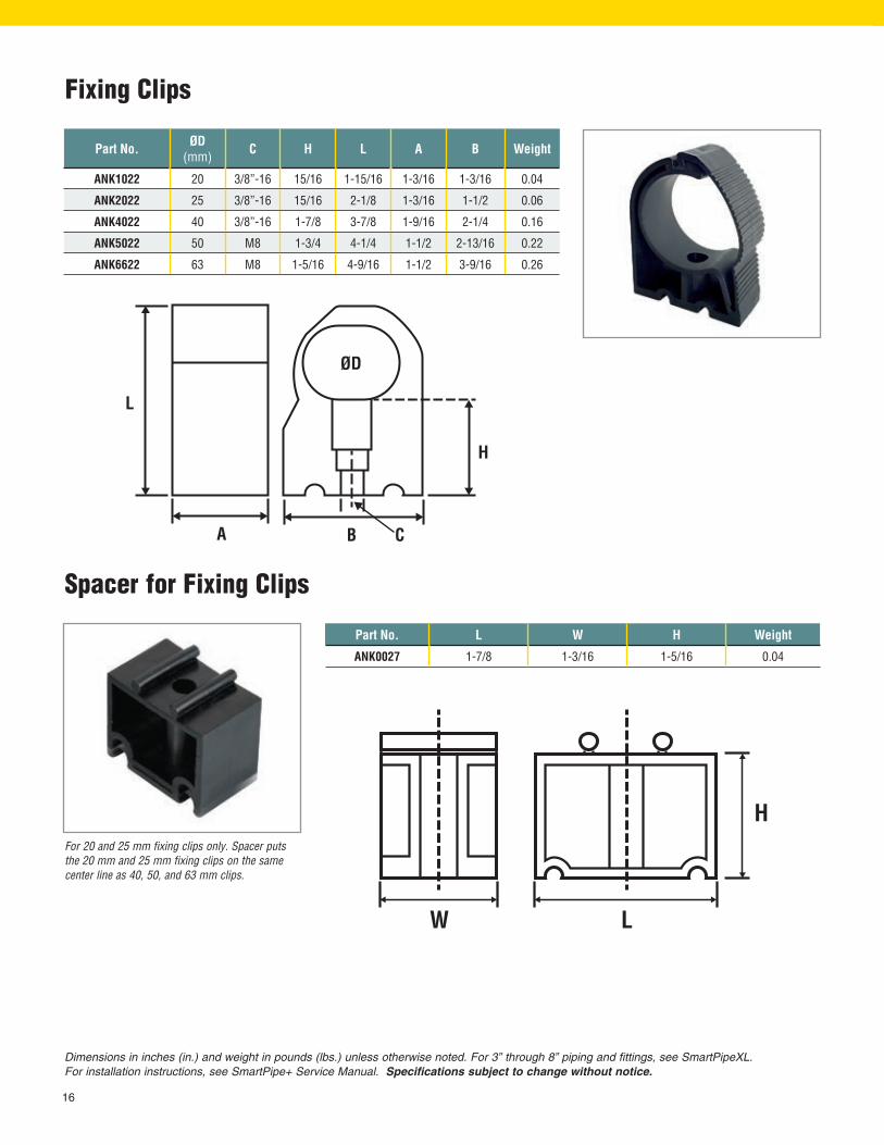
Part No. L W H Weight
ANK0027 1-7/8 1-3/16 1-5/16 0.04
Spacer for Fixing Clips
For 20 and 25 mm fixing clips only. Spacer puts the 20 mm and 25 mm fixing clips on the same center line as 40, 50, and 63 mm clips.
Fixing Clips
Part No. ØD(mm) C H L A B Weight
ANK1022 20 3/8”-16 15/16 1-15/16 1-3/16 1-3/16 0.04
ANK2022 25 3/8”-16 15/16 2-1/8 1-3/16 1-1/2 0.06
ANK4022 40 3/8”-16 1-7/8 3-7/8 1-9/16 2-1/4 0.16
ANK5022 50 M8 1-3/4 4-1/4 1-1/2 2-13/16 0.22
ANK6622 63 M8 1-5/16 4-9/16 1-1/2 3-9/16 0.26

17
Dimensions in inches (in.) and weight in pounds (lbs.) unless otherwise noted. For 3” through 8” piping and fittings, see SmartPipeXL. For installation instructions, see SmartPipe+ Service Manual. Specifications subject to change without notice.
Accessories
Mini Bracket
Part No. ØD x NPT(mm x in.) A A1 A2 B B1 B2 C Weight
AN8983502504 25 x 1/2 2-7/16 1 1-7/16 2 11/16 1-5/16 1-5/16 0.16
AN8983504004 40 x 1/2 3-9/16 1-5/8 1-15/16 2-3/4 1-1/16 1-11/16 1-7/8 0.36
AN8983505006 50 x 3/4 4 1-13/16 2-3/16 3-5/16 1-1/4 2-1/16 1-7/8 0.45
AN8983506306 63 x 3/4 4-13/16 2-5/16 2-1/2 3-7/8 1-9/16 2-5/16 2-1/4 0.78
Note: Requires hole saw bit to drill pipe. 1/2” = 14 mm hole saw drill bit (ANK0043). 3/4” = 19 mm hole saw drill bit (ANK0143).ANK0243 Drill arbor and pilot bit also required
Part No. C1 E H K Weight
ANK0026 M8 3/4 1-13/16 3/8”-16 0.05
Threaded Rod Adapter
For use with fixing clips with M8 connections only.

18
Dimensions in inches (in.) and weight in pounds (lbs.) unless otherwise noted. For 3” through 8” piping and fittings, see SmartPipeXL. For installation instructions, see SmartPipe+ Service Manual. Specifications subject to change without notice.
Wall Manifold
Part No. NPT Fig. A B C E F G H I Wt.
AN89844069043/4 x 1/2
1 22-3/16 2-1/2 1 1/2 NPT 3/4 NPT 1/4 1
0.4
AN8984706904 2 6-1/16 1.4
Fig. 1
Fig. 2
MOUNTING HARDWARE NOT INCLUDED. Manifold ships as shown without plugs.

19
Accessories
45° Threaded Wall Brackets
Part No. ØD x NPT(mm x in.) Fig. A B F G M Wt.
AN8984102504 25 x 1/2 13-7/8 3-1/8 1/4 15/16 3-1/4
0.35
AN8984202504 25 x 1/2 x 1/2 2 0.39
Fig. 1
Fig. 2
Note: Wall bracket requires an additional 25 mm fitting or 25 mm ball valve in order to connect to the pipe. Can use 20 x 25 mm ball valve (AN8988102520) to connect 20 mm pipe or a 25 mm fitting and a 25 x 20 plug-in reducer (AN8202502502).
Dimensions in inches (in.) and weight in pounds (lbs.) unless otherwise noted. For 3” through 8” piping and fittings, see SmartPipeXL. For installation instructions, see SmartPipe+ Service Manual. Specifications subject to change without notice.
Quick Reducing Bracket
Part No. ØD x ØD2(mm) A A1 A2 B B1 B2 C S Weight
AN8983002549 25 x 1/2 NPT 3-15/16 2-1/2 1-7/16 2-3/4 2-1/16 11/16 1-5/16 1-1/8 0.38
AN8983002502 25 x 20 4-7/16 3 1-7/16 2-3/4 2-1/16 11/16 1-5/16 1-1/8 0.36
AN8983004002 40 x 20 5-9/16 3-11/16 1-7/8 3-15/16 2-7/8 1-1/16 1-1/2 1-1/8 0.77
AN8983004025 40 x 25 5-5/8 3-3/4 1-7/8 3-15/16 2-7/8 1-1/16 1-1/2 1-7/16 0.71
AN8983005020 50 x 20 5-15/16 3-3/4 2-3/16 4-7/16 3-3/16 1-1/4 1-1/2 1-1/8 0.86
AN8983005002 50 x 25 5-15/16 3-3/4 2-3/16 4-7/16 3-3/16 1-1/4 1-1/2 1-7/16 1.26
AN8983006320 63 x 20 6-3/4 4-1/4 2-1/2 5-3/16 3-5/8 1-9/16 1-1/2 1-1/8 1.26
AN8983006302 63 x 25 6-7/8 4-3/8 2-1/2 5-3/16 3-5/8 1-9/16 1-1/2 1-7/16 1.15
Note: Requires hole saw bit to drill pipe. AN8983002502 (25 mm x 20 mm) use ANK0043. All others use ANK00143. ANK0243 also required.

20
Dimensions in inches (in.) and weight in pounds (lbs.) unless otherwise noted. For 3” through 8” piping and fittings, see SmartPipeXL. For installation instructions, see SmartPipe+ Service Manual. Specifications subject to change without notice.
Ball Valve (Pipe to Pipe)
Part No. ØD(mm) A B1 B E G L S Weight
AN8988102002 20 5-3/16 2-7/8 4-1/4 1-9/16 3-7/8 1-3/8 1-1/8 0.5
AN8988102520 20 x 25 5-3/16 2-7/8 4-1/4 1-9/16 4 1-7/16 1-7/16 0.85
AN8988102502 25 5-15/16 3-7/16 4-13/16 2 4-3/8 1-7/16 1-7/16 0.55
AN8988104004 40 5-3/8 4-3/4 6-7/8 2-13/16 6-5/8 2-1/4 2-1/16 2.1
AN8988105005 50 11-1/8 6-1/8 9-1/4 3-1/2 7-7/8 2-11/16 2-5/8 3.66
AN8988106306 63 12-1/16 6-15/16 9-13/16 4-5/16 10 3-1/4 3-1/4 6.28
Ball Valve (Pipe to Thread)
Part No. ØD x NPT(mm x in.) A B1 B E G L S Weight
AN8988202004 20 x 1/2 5-3/16 2-7/8 4-1/4 1-9/16 3-11/16 1-3/8 1-1/8 0.45
AN8988202506 25 x 3/4 5-15/16 3-7/16 4-13/16 2 4-1/8 1-7/16 1-7/16 0.8
AN8988204010 40 x 1-1/4 8 4-3/8 6-11/16 2-3/8 5-3/16 1-13/16 1-11/16 1.9
AN8988205012 50 x 1-1/2 8-3/8 4-3/4 6-7/8 2-13/16 5-3/4 2-1/4 2-1/16 3.26
AN8988206316 63 x 2 11-1/8 6-1/8 9-1/4 3-1/2 7-3/8 2-11/16 2-5/8 5.18

21
Dimensions in inches (in.) and weight in pounds (lbs.) unless otherwise noted. For 3” through 8” piping and fittings, see SmartPipeXL. For installation instructions, see SmartPipe+ Service Manual. Specifications subject to change without notice.
Accessories
Hose (Pipe to Pipe)
Part No. ØD(mm) L MATL 1 MATL 2 A Weight
AN8992002010 20 11-13/16
Aluminum Rubber
15-1/4 0.95
AN8992002011 20 39-3/8 42-13/16 1.95
AN8992002510 25 11-13/16 15-1/2 1.4
AN8992002511 25 39-3/8 43-1/16 2.78
AN8992004010 40 19-11/16 25-3/16 3.37
AN8992004011 40 39-3/8 44-7/8 5.0
AN8992005010 50 19-11/16 26 5.3
AN8992005011 50 39-3/8 45-11/16 5.7
AN8992006310 63 19-11/16 27-3/16 8.5
AN8992006311 63 39-3/8 46-7/8 11.2
Use part number AN66989903, anti-whiplash strap. Refer to installation information for proper bend radius and proper installation practices. Requires additional SmartPipe+ fittings to install.
45° Wall Bracket with Ball Valve
Part No. ØD x NPT(mm x in.) Fig. Ports Wt.
AN8988502005 20 x 1/2 1 1 port 0.8
AN8988602004 20 x 1/2 x 1/2 2 2 port 0.9
AN8988502505 25 x 1/2 1 1 port 1.15
AN8988602504 25 x 1/2 x 1/2 2 2 port 1.2
Fig. 1 Fig. 2

22
Dimensions in inches (in.) and weight in pounds (lbs.) unless otherwise noted. For 3” through 8” piping and fittings, see SmartPipeXL. For installation instructions, see SmartPipe+ Service Manual. Specifications subject to change without notice.
Vented End Cap
Part No. ØD(mm) A B C S Weight
AN89865020 20 1-7/8 13/16 7/8
11/16
0.08
AN89865025 25 2-1/4 1 1-1/8 0.10
0AN89865040 40 2-13/16 1-9/16 1-3/4 0.20
AN89865050 50 3-1/4 2 2-3/16 0.36
AN89865063 63 3-7/8 2-1/2 2-13/16 0.64
Note: Will require separate SmartPipe+ fitting
Lockable Handle
Part No. ØD (mm) Weight
AN89888020 20 0.10
AN89888025 25 0.15
AN89888040 40 0.25
AN89888050 50 0.44
AN89888063 63 0.52
Anti-whiplash Strap
Part No. Weight
AN66989903 0.47
Prevents whiplash should SmartPipe+ flexible hose be disconnected while under pressure. Conforms to ISO 4414 safety standard. See installation infor-mation for proper installation practices.

23
Dimensions in inches (in.) and weight in pounds (lbs.) unless otherwise noted. For 3” through 8” piping and fittings, see SmartPipeXL. For installation instructions, see SmartPipe+ Service Manual. Specifications subject to change without notice.
Accessories
Pipe Marking Tool
Pipe Cutter
Part No. L H Weight
ANK0040 10-1/16 3-7/8 1.94
Part No. L A B C Weight
AN89531001 8-7/8 1-3/8 1-7/16 1-9/16 0.09
ANK0040, 20 mm - 63 mm (3/4” to 2½”) Pipe Cutter, uses replacement blades ANK0240.

24
Dimensions in inches (in.) and weight in pounds (lbs.) unless otherwise noted. For 3” through 8” piping and fittings, see SmartPipeXL. For installation instructions, see SmartPipe+ Service Manual. Specifications subject to change without notice.
Part No. Fig. Description Weight
ANK0141 1 20 mm - 50 mm (3/4” to 2”) Pipe Deburrer 1.27
AN113835 2 20 mm - 50 mm Manual/Electric Pipe Deburrer 1.00
ANK0042 3 Hole Deburrer 0.08
AN292110 4 63 mm (2-1/2”) Chamfer Tool 1.38
Deburrer and Chamfer Tools
Part No. Description Weight
ANK0043 14 mm Hole Saw Bit 0.04
ANK0143 19 mm Hole Saw Bit 0.30
ANK0243 Drill Arbor and Pilot Bit (14 mm to 25 mm) 0.20
Hole Saw Bits
Fig. 2
Fig. 1
Fig. 3 Fig. 4 Uses replacement blade AN292011
Drill arbor and pilot bit Hole saw bits

25
Accessories
Composite Quick-Connect Couplers and Plugs
SmartPipe couplers are designed for easy one-handed con-
nection and disconnection. To connect, simply press the plug
into the coupler port. To disconnect, pull the coupler sleeve to
release the plug.
Pressure Loss in psi
psi
cfm
Cv rating = 1.24
Pressure Loss in Couplers
Universal Coupler (ISO 6150B/Automotive)
Part No. Nipple NPT
ANK4184 1/4” 1/4”
ANK8184 3/8” 3/8”
Part No. Nipple NPT
ANK1484 1/4” 1/2”
ANK3884 3/8” 1/2”
Industrial Nipples (ISO B)
Automotive Nipples
Part No. Nipple NPT
ANK4284 1/4” 1/4”
ANK8284 3/8” 3/8”

26
Warranty
Product Warranty RegistrationIn order for Kaeser Compressors, Inc. to properly handle warranty or other service requests,
please register online at us.kaeser.com/warranty.
us.kaeser.com/warranty
AUTHORIZATION FROM THE SERVICE DEPARTMENT IS NECESSARY BEFORE MATERIAL IS RETURNED TO THE FACTORY OR IN-WARRANTY REPAIRS ARE MADE.
Model: _____________________Serial No: ______________________Start-up Date: _________________
Kaeser Compressors, Inc. herein referred to as “Kaeser,” warrants the Kaeser SmartPipe+™ delivered hereunder will be free of defects in material and workmanship for a period of ten (10) years from the date of purchase of the products.
Kaeser does not warranty the design, assembly or installation of the system, but only the components as stated herein. Kaeser is not responsible for improper design, assembly or installation, or for any modifications of the Kaeser products.
Should any failure to conform with the above warranties occur during the specified period under normal use, and the components have been proven to Kaeser’s satisfaction to have been properly stored, installed and maintained, and purchaser has complied with all procedures outlined in the service manual or installation instructions then Kaeser shall, with prompt notice correct the non-conformities at its option either by replacement or by refund of the purchase price of the non-conforming equipment. Return of such component to such delivery point as Kaeser may direct pursuant to this paragraph shall be at the purchaser’s risk and expense. Kaeser warrants any components replaced pursuant to the above warranty, under normal use, to be free from defects in workmanship and material for a period of ninety (90) days after the shipment of such replaced components or for a period ending on the expiration of the original component warranty, whichever is longer. Unless otherwise expressly agreed, Kaeser shall not be responsible for labor charges, loss or damage resulting from improper operation, maintenance or repairs made by personnel other than those authorized in writing by Kaeser, or damage to equipment caused by the use of non-authorized replacement parts.
Replacement or refund (whichever Kaeser determines, in its sole discretion, to provide) shall be Kaeser’s sole obligation and purchaser’s exclusive remedy for any nonconformity, noncompliance, defect or deficiency in components furnished hereunder, and shall be conditioned upon purchaser’s return of the defective components to Kaeser (DAP Kaeser’s directed delivery point) if Kaeser requires such return. This exclusive remedy will not be deemed to have failed of its essential purpose so long as Kaeser is willing to provide replacement or refund. THE EXPRESS WARRANTY CONTAINED HEREIN IS EXCLUSIVE AND IN LIEU OF ALL OTHER REPRESENTATIONS AND WARRANTIES, EXPRESSED OR IMPLIED, AND KAESER EXPRESSLY DISCLAIMS AND EXCLUDES ANY IMPLIED WARRANTY OF MERCHANTABILITY OR FITNESS FOR ANY PARTICULAR PURPOSE, AND ANY WARRANTIES ARISING FROM COURSE OF DEALING OR USAGE OF TRADE.
SmartPipe+™3/4” to 2-1/2”

27
Kaeser Compressors, Inc.511 Sigma DriveFredericksburg, VA 22408 USA Telephone: 540-898-5500Toll Free: [email protected]
us.kaeser.com
LIMITATION OF LIABILITY
THE REMEDIES OF THE PURCHASER SET FORTH HEREIN ARE EXCLUSIVE, AND KAESER COMPRESSORS’ LIABILITY WITH RESPECT TO EQUIPMENT SOLD HEREUNDER SHALL BE LIMITED TO THE WARRANTY PROVIDED HEREIN AND, WITH RESPECT TO ANY BREACH OF ITS CONTRACT WITH PURCHASER, SHALL BE LIMITED TO THE CONTRACT PRICE OF EQUIPMENT THAT IS THE SUBJECT OF THE BREACH; PROVIDED, HOWEVER, THAT THE FOREGOING SHALL NOT APPLY IN THE EVENT OF ANY ACT THAT CONSTITUTES GROSS NEGLIGENCE OR WILLFUL MISCONDUCT BY THE PARTY SUBJECT TO THE CLAIM FOR SUCH DAMAGES. PRIOR TO PURCHASER HAVING ANY RIGHT TO RECOVER DAMAGES (SUBJECT TO THE LIMITATIONS SET FORTH BELOW), KAESER COMPRESSORS SHALL HAVE THE RIGHT TO CORRECT ANY DEFECT OR NON-CONFORMITY OF ANY EQUIPMENT SOLD HEREUNDER IN A REASONABLE TIME FRAME, AND IF KAESER COMPRESSORS DETERMINES THAT IT IS UNABLE OR UNWILLING TO CORRECT ANY SUCH DEFECT OR NON-CONFORMITY, THEREAFTER, PURCHASER MAY PURSUE THE ALTERNATIVE REMEDIES SET FORTH HEREIN. NOTWITHSTANDING ANYTHING HEREIN TO THE CONTRARY, IN NO EVENT SHALL EITHER PARTY BE LIABLE FOR SPECIAL, INDIRECT, INCIDENTAL, CONSEQUENTIAL OR PUNITIVE DAMAGES, OR EXPENSES INCURRED BY THE OTHER PARTY, THE OTHER PARTY’S CUSTOMERS OR ANY THIRD PARTY, WHETHER ARISING FROM BREACH OF CONTRACT, WARRANTY, NEGLIGENCE, STRICT LIABILITY IN TORT OR OTHER THEORIES OF LAW OR EQUITY, INCLUDING BUT NOT LIMITED TO LOSS OF PROFITS OR REVENUE, LOSS OF USE OF EQUIPMENT OR ANY ASSOCIATED EQUIPMENT, COST OF CAPITAL, COST OF SUBSTITUTE FACILITIES OR SERVICES, DOWNTIME COSTS OR CLAIMS OF CUSTOMERS OR SUCH OTHER PARTY FOR SERVICE INTERRUPTION, OR ANY OTHER TYPES OF ECONOMIC LOSS WHETHER OR NOT SUCH LOSS OR DAMAGE IS BASED ON CONTRACT, WARRANTY, NEGLIGENCE, INDEMNITY, STRICT LIABILITY OR OTHERWISE.
© 2018 Kaeser Compressors, Inc. All rights reserved. 06/18

As one of the world’s largest compressed air systems providers and compressor manufacturers, Kaeser Compressors is represented throughout the world by a comprehensive network of branches, subsidiary companies and factory trained partners.
With innovative products and services, Kaeser Compressors’ experienced consultants and engineers help customers to enhance their competitive edge by working in close partnership to develop progressive system concepts that continuously push the boundaries of performance and compressed air efficiency. Every Kaeser customer benefits from the decades of knowledge and experience gained from hundreds of thousands of installations worldwide and over ten thousand formal compressed air system audits.
These advantages, coupled with Kaeser’s worldwide service organization, ensure that our compressed air products and systems deliver superior performance with maximum uptime.
The world is our home
© 2020 Kaeser Compressors, Inc. All rights reserved. 05/20USSPLUSPARTS
Kaeser Compresores de Guatemala y Cia. Ltda.Calz. Atanasio Tzul 21-00, zona 12 El Cortijo II, Bodega 50101012–Guatemala CityTelephone: +502 [email protected]
Kaeser Compresores de México S de RL de CVCalle 2 #123Parque Industrial Juríca 76100 Querétaro, Qro.Telephone: 01 (442) 218 64 [email protected]
Kaeser Compressors Canada Inc.3760 La Vérendrye StreetBoisbriand, QC J7H 1R5 CANADA Telephone: (450) 971-1414Toll free: (800) 477-1416 [email protected]
Kaeser Compressors, Inc.511 Sigma DriveFredericksburg, VA 22408 USA Telephone: 540-898-5500Toll Free: [email protected]
www.kaeser.com