3.6 intersymbol interference - uestc · what is intersymbol interference and what cause isi 2. the...
TRANSCRIPT

11 Your site here
3.6 Intersymbol interference

22 Your site here
what is intersymbol interference and what cause ISI
2. The channels property is not plat. Pulses are filtered improperly as they through channel, they will spread in time.
1. The absolute bandwidth of rectangular multilevel pulses is infinite. The channels bandwidth is limited.
3.6 Intersymbol interference

33 Your site here
Fig 3-23
1
1 11
0 0 0
0码间串扰
0
0 0
0 0
0t→
t→ t→
t→
t→
t→
Ts Tssample point(receiver clock)
Ts
Input waveform win(t)
Sample points (transmitter clock)
individual impulse response
sample point
received waveformwout(t)(pulse response sum)
(receiver clock)
Intersymbol interference
44 Your site here
How can we restrict the bandwidth and still not introduce ISI?
problem
Nyquist discovered three different methodsfor pulse shaping that could be used to eliminate ISI.
Intersymbol interference

55 Your site here
The digital signaling system :
win(t) wc(t) wout(t)send filterhT( t ) HT( f )
channel(filter)hC( t )HC( f )
receiver filterhR( t )HR( f ) recovered rounded pulse
(to sample and decodecircuit)
The equivalent impulse response is
he(t)=h(t)*hT(t)*hC(t)*hR(t)
The equivalent system transfer function :
He( f )=H( f ) HT( t ) HC( f ) HR( f )
Intersymbol interference

66 Your site here
If the equivalent system impulse response satisfies the condition
he(kTs+τ)=C , k=0
0 , k≠0
C is a nonzero constant, K is an integer, Ts is the symbol (sample ) clocking period, τis the offset in the receiver sampling clock times, compared with the clock times of the input symbols.
Nyquist’s First Method (zero ISI)
It will eliminating ISIWhere :

77 Your site here
Ts 2Ts 3Ts-2Ts -Ts-3Tsfs/2-fs/2
tftfth
s
se π
πsin)( =∏ ⎟⎟
⎠
⎞⎜⎜⎝
⎛=
sse f
ff
fH 1)(
If we choose a (sinx)/x function for he(t), the impulse response satisfies Nyquist’s first criterion for zero ISI.
tftfth
s
se π
πsin)( =ss Tf /1=where
Nyquist’s First Method (zero ISI)

88 Your site here
If the transmit and receive filters are designed so that the overall transfer function is
There will be no ISI, furthermore, the absolute bandwidth of this transfer function is
∏ ⎟⎟⎠
⎞⎜⎜⎝
⎛=
sse f
ff
fH 1)(
2/sfB =
Difficulties:
He( f ) is difficult to approximate because of the steep skirts in the filter transfer function
The synchronization of the clock in the decoding sampling circuit has to be almost perfect.
Ts 2Ts 3Ts-2Ts -Ts-3Ts
fs/2-fs/2
tftfth
s
se π
πsin)( =∏ ⎟⎟
⎠
⎞⎜⎜⎝
⎛=
sse f
ff
fH 1)(
Nyquist’s First Method (zero ISI)

99 Your site here
Because of these difficulties, we are forced to consider other pulse shapes
The idea is to find pulse shapes that go through zero at adjacent sampling points, and yet have an envelope that decays much faster than 1/x , so that clock jitter in the sampling times does not cause appreciable ISI
Solution: Raised cosine-rolloff Nyquist filter
Nyquist’s First Method (zero ISI)

1010 Your site here
Raised cosine-rolloff Nyquist filter
The raised cosine-rolloff Nyquist filter has the transfer function
⎪⎪
⎩
⎪⎪
⎨
⎧
>
<<⎪⎭
⎪⎬⎫
⎪⎩
⎪⎨⎧
⎥⎦
⎤⎢⎣
⎡ −+
<
=Δ
Bf
Bfff
ff
ff
fH e
,0
,2
)(cos1
21
,1
)( 11
1
π
0ffr Δ=
Where B is the absolute bandwidth
f0 is 6dB bandwidth of the filter
The rolloff factor is defined:
,, 010 ΔΔ −=−= ffffBf

1111 Your site here
[ ] ⎥⎦
⎤⎢⎣
⎡−⎟⎟
⎠
⎞⎜⎜⎝
⎛==
Δ
Δ−2
0
00
1
)4(12cos
22sin2)()(
tftf
tftfffHFth ee
πππ
The corresponding impulse response is:
As the absolute bandwidth is increased (r=0.5 or 1):
1. The filtering requirements are relaxed.
2. The clock timing requirements are also relaxed.
Frequency and time response for different rolloff factor
Raised cosine-rolloff Nyquist filter

1212 Your site here
The baud rate that the raised cosine-rolloffsystem can support without ISI
02/1 fTD s ==
The 6-dB bandwidth of the raised cosine-rollofffilter f0 is designed to be half the symbol (baud) rate.
)2/(1 0fTs =
rBD+
=12
2/0 Df =
0fBf −=Δ
0/ ffr Δ=
rBf+
=10
Raised cosine-rolloff Nyquist filter

1313 Your site here
Example 3-1
Assume that a binary digital signal, with Polar NRZ signaling, is pass through a communication system with a raised cosine-rolloff filtering charcteristic.
Let the rolloff factor be 0.25. the bit rate of the digital signal is 64 kbit/s.
Determine the absolute bandwidth of the filtered digital signal.
Raised cosine-rolloff Nyquist filter

1414 Your site here
The raised cosine-rolloff filter is only one of a more general class of filters that satisfy Nyquist’s first criterion
The general class of filters that satisfy Nyquist’s first criterion---- Nyquist filter.
Raised cosine-rolloff Nyquist filter

1515 Your site here
Nnyquist filter
A filter is said to be a Nyquist filter if the effective transfer function is
⎪⎩
⎪⎨
⎧<+⎟⎟
⎠
⎞⎜⎜⎝
⎛= ∏
elsewheref
fffYff
fH e
,0
2,)(2)( 0
0
where Y( f ) is a real function that is even symmetric about f =0
Y( -f )=Y( f ) , | f | < 2 f 0
Y( -f + f 0 ) = -Y( f+ f 0 ) , | f | < f 0
And Y( f ) is odd symmetric about f = f0
Then there will be no ISI at the system output if the symbol rate is
02 ffD s ==

1616 Your site here
⎪⎩
⎪⎨
⎧<+⎟⎟
⎠
⎞⎜⎜⎝
⎛= ∏
elsewheref
fffYff
fHe
,0
2,)(2)( 0
0
Nnyquist filter

1717 Your site here
Nyquist second and third methods for control of ISI
Nyquist’s second method (ISI control)Allows some ISI to be introduced in a controlled way, so that it can be canceled out the receiver and the data can be recovered without error if no noise is present.
Nyquist’s third method (ISI control)The effect of ISI is eliminated by choosing he(t):the area under he(t) pulse within the desired symbol interval, Ts, is not zero, but the areas under he(t) in adjacent symbol intervals are zero.

1818 Your site here
3.7 Differential pulse code modulation

1919 Your site here
Differential pulse code modulation
The reason of we use DPCMThere is a lot of redundancy in the signal samples.
The bandwidth and the dynamic range of a PCM system are wasted
Solution To transmit the difference in adjacent sample values. That is, to use Differential pulse code modulation (DPCM)
MethodTo use prediction filter in
k
iin xax −
=∑=
1

2020 Your site here
DelayTs
DelayTs
DelayTs
a1 a2 al ak
…
z(nTs)
…. ….
Y(nTs)
Prediction filter may be realized by using a tapped delay line to form a transversal filter
The output samples are
∑=
−=K
lssls lTnTyanTz
1)()(
∑=
−=K
llnln yaz
1In simplified notation:
Differential pulse code modulation

2121 Your site here
The first configurationusing prediction from samples of input signal
Differential pulse code modulation

2222 Your site here
The second configurationusing prediction from quantized differential signal
Differential pulse code modulation
2323 Your site here
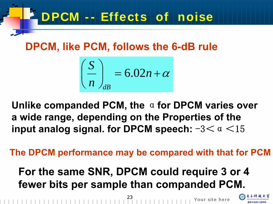
DPCM -- Effects of noise
DPCM, like PCM, follows the 6-dB rule
α+=⎟⎠⎞
⎜⎝⎛ n
nS
dB
02.6
Unlike companded PCM, the αfor DPCM varies over a wide range, depending on the Properties of the input analog signal. for DPCM speech: -3<α<15
The DPCM performance may be compared with that for PCM
For the same SNR, DPCM could require 3 or 4 fewer bits per sample than companded PCM.

2424 Your site here
DPCM standard
A 32-Kbits⁄s DPCM CCITT standard:To use 4-bit quantization at an 8-Ksample⁄s rate for encoding 3.2-KHz bandwidth VF signals.
A 64-Kbits⁄s DPCM CCITT standard:To use 4-bit quantization and 16-Ksample⁄s for encoding audio signals that have a 7-KHz bandwidth.
2525 Your site here
3.8 Delta modulation

2626 Your site here
Delta modulation
DM—Delta Modulation. It is a special case of DPCM.
+vc
-vc
Cn=1
Cn=0Characteristics:◆ There are only two
quantizing levels
◆ Only one bit is transmitted per sample.
◆ ……

2727 Your site here
DM system waveformsDM system waveforms

2828 Your site here
δ
Granular noise Granular noise && slope slope overload noiseoverload noise
Slope overload noise Granular noise
δ
Slope overload noise will decrease as δ increase.
Granular noise will decrease as δdecrease.
wish wish

2929 Your site here
Granular noise Granular noise &&slope overload slope overload noisenoise
Granular noise Granular noise && slope slope overload noiseoverload noise

3030 Your site here
Example 3-5: Design of a DM system.
problem: find the step size δ required to prevent slope overload noise for the case when the input signal is a sine wave.
Granular noise Granular noise && slope slope overload noiseoverload noise
δ
tAtw aωsin)( =
t

3131 Your site here
the granular noise power in the analog output signal band:
s
BB n f
BfpnN df3
)(2
2 δ=∫−=><=
From eq.(3-84),with equality:
2
222
34
s
af
BfAN
π=
SNR for the DM systemSNR for the DM system
The signal power is (for a sine-wave test signal)
2)(
22 AtwS >==<

3232 Your site here
The resulting average signal-to-quantizing noise ratio:
--- the DM sampling frequency---the frequency of the sinusoidal input ---the bandwidth of the receiving system
Attention: This Eq. is valid only for sinusoidal-type signal
Bf
f
outNS
a
s2
3
283π
=⎟⎟
⎠
⎞
⎜⎜
⎝
⎛
sf
afB
SNR for the DM systemSNR for the DM system

3333 Your site here
Adaptive Delta modulation and continuously Adaptive Delta modulation and continuously variable slope Delta modulationvariable slope Delta modulation
Adaptive Delta modulation ADMAdaptive Delta modulation ADM :the step size vary as a function of time as the input waveform changes.
When signal
When signal δ
δ

3434 Your site here
The step size may be adapted by examining the DM pulses at the transmitter output.
When the DM pulses consists of a string of pulses with the same polarity, the step size is increased until the DM pulses begin to alternate in polarity, then the step size is decreased, and so on.
Method 1
Adaptive Delta modulation and continuously Adaptive Delta modulation and continuously variable slope Delta modulationvariable slope Delta modulation

3535 Your site here
step-size Algorithm:
X: don’t care
Adaptive Delta modulation and continuously Adaptive Delta modulation and continuously variable slope Delta modulationvariable slope Delta modulation
441 1 1 1
230 1 1 1
2x 0 1 1
1x x 0 1
Step-size Algorithm
f(d)
Number of Successive Binary
1’s or 0’sData Sequence
δδ
δδ

3636 Your site here
continuously variable slope delta modulation (CVSD)
CVSD is another variation of ADM
An integrator (instead of accumulator) is used, so that z(t) is made continuously variable
Product The Motorola MC34115The Motorola MC3418
Method 2

3737 Your site here
Summary
Question
Which is better, PCM or DM?
The answer depends on the criterion used for comparison and the type of message.
To have a relatively simple, low-cost system, DM may be the bestTo have a high output SNR, PCM probably the bestTo interface existing equipment, compatibility, PCM has the advantage.

3838 Your site here
3.9 TimeTime--Division Multiplexing Division Multiplexing (TDM)(TDM)
3939 Your site here
TimeTime--Division Multiplexing (TDM)Division Multiplexing (TDM)
Aims: to make use of the channel bandwidthto achieve high spectral efficiency
Why we must use TDM?
What is the TDM?TDM (Time-division multiplexing) is the time interleaving of samples from several sourcesso that the information form these sources can be transmitted serially over a single communication channel.

4040 Your site here
three analog sources are multiplexed over a PCM system.
TimeTime--Division Multiplexing (TDM)Division Multiplexing (TDM)

4141 Your site here
s
s
nfnT
31
3=
s
s
fT
31
3=
TDM PAM
3Ts
The pulse width of the TDM PAM:
The pulse width of the TDM PCM:
Ts
TimeTime--Division Multiplexing (TDM)Division Multiplexing (TDM)

4242 Your site here
Aims of the frame sync. : To make the received multiplexed data can be sorted and directed to the appropriate output channel at the TDM receiver.
The frame sync. Signal can be provided to the receiver demultiplexer by:
Sending a frame sync signal over a separate channel
Deriving the frame sync from the TDM signal itself
Frame synchronizationFrame synchronization..

4343 Your site here
Frame synchronization word:A segmented bits data stream which obeys some rules. Usually, it should be unique in the data stream, or at least, the appear probability is very small.
Frame synchronizationFrame synchronization..
s1 s2 sk Ch. 1data
Ch. 2data
Ch. Ndata s1 s2 sk
…… …… …

4444 Your site here
Example 3.6Design a time-division multiplexer that will accommodate 11 sources, assume that the sources have the following specifications:
Source 1. analog, 2-kHz bandwidthSource 2. analog, 4-kHz bandwidthSource 3. analog, 2-kHz bandwidthSources 4-11. digital, synchronous at 7200 bits/s.
TimeTime--Division Multiplexing (TDM)Division Multiplexing (TDM)

4545 Your site here
Example
TimeTime--Division Multiplexing (TDM)Division Multiplexing (TDM)

4646 Your site here
The preceding example illustrates the main advantage of TDM:
It can easily accommodate both analog and digital sources.
Unfortunately, when analog signals are converted to digital signals without redundancy reduction, they consume a great deal of digital system capacity.
TimeTime--Division Multiplexing (TDM)Division Multiplexing (TDM)

4747 Your site here
TDM hierarchy
Two categories:TDM used in digital computer system
TDM used by common carrier
The output rate has been standardized to 1.2, 2.4, 3.6, 4.8, 7.2, 9.6, 14.4, 19.2, 28.8 kb/s. and to 10 and 100 to 1000Mb/s, 10Gb/s.
North American digital TDM hierarchy
Europe digital TDM hierarchy (CCITT TDM)

4848 Your site here
North American digital TDM hierarchy:( T1 TDM system )
TDM hierarchy

4949 Your site here
24-VF analog telephone signals are converted to a DS-1 (1.544 Mbit/s) data streamThe sampling rate used on each of the 24-VF analog signals is 8 kHzEach analog sample is encoded into an 8-bit PCM wordThere are 8*24=192 bits of data, plus one bit is addedfor frame synchronization, yielding a total of 193 bits per fram.
TDM hierarchy

5050 Your site here
Europe digital TDM hierarchy:
(CCITT TDM standard)
TDM hierarchy