joint intersymbol and multiple-access interference suppression
TRANSCRIPT

In European Trans. Telecommunications, Special Issue on CDMA
Techniques for Wireless Communication Systems, vol. 9, no. 5,
pp. 403-418, Sept./Oct. 1998. (invited paper)
Joint Intersymbol and Multiple-Access Interference
Suppression Algorithms for CDMA Systems
Soosan Beheshti, Steven H. Isabelle, and Gregory W. Wornell,
February 1998
Abstract
Two promising classes of techniques are developed for e�cient multiuser detection in code-
division multiple-access (CDMA) communication systems subject to fading due to time-varying
multipath propagation. Both are designed to jointly suppress both intersymbol and multiple-
access interference inherent in such systems, and exploit all available time and frequency diver-
sity.
The �rst is a family of linear receivers for time-varying multiuser channels that generalize
familiar linear equalizers designed for traditional single-user linear time-invariant channels. Min-
imum mean-square error, zero-forcing, and matched-�lter versions of such multiuser detectors
are all developed within a common state-space framework, and have convenient recursive im-
plementations. Performance issues as well as natural decision-feedback variants of the detector
structure are both discussed.
The second is a family of nonlinear receivers that are speci�cally designed for use with
spread-signature CDMA systems on time-varying multipath channels. These multiuser detec-
tors employ a batch-iterative (multipass) decoding algorithm based on a successive-cancellation
strategy. Several aspects of the performance of this algorithm are developed, including its
monotonic convergence property.
Collectively, these two classes of algorithmic structures for joint equalization, interference
suppression, demodulation, and detection are representative of several emerging and interrelated
approaches to receiver design for next-generation CDMA systems.
Index Terms|code-division multiple-access, wireless communications, fading channels, equal-
ization, spread-response precoding, spread-signature CDMA, multiuser detection, interference
cancellation, iterative decoding, stripping, multipass algorithms
1 Introduction
In a wide-range of wireless communication applications, there is a need for users to be able to
communicate e�ciently and asynchronously among themselves in the presence of fading due to
This work has been supported in part by the O�ce of Naval Research under Grant No. N00014-96-1-0930, the
National Science Foundation under Grant No. MIP-9502885, and the Army Research Laboratory under Cooperative
Agreement DAAL01-96-2-0002.
S. Beheshti and G. W. Wornell are with the Department of Electrical Engineering and Computer Science, Mas-
sachusetts Institute of Technology, Cambridge, MA 02139, as was S. H. Isabelle. S. H. Isabelle is now with Solana
Technology Corp., San Diego, CA 92122.
1

multipath propagation. For example, in a cellular mobile radio environment, the transmissions
of the individual mobiles pass through generally distinct channels, and a noisy version of their
superposition is obtained at the base station. In such scenarios, obtaining reliable estimates of the
symbols transmitted by a particular user (or all users) requires the mitigation of several sources of
interference.
In CDMA systems, where all users spread their transmission over a common transmission
bandwidth, a dominant impairment is interference between users, referred to as multiple-access
interference. There is a substantial literature on the problem of multiple-access interference sup-
pression in wireless systems, and a wide range of e�cient algorithms have been proposed for use in
receivers|see, e.g., [1] [2] [3] [4], as well as [5] and the references therein. In much of this literature,
attention is restricted to the case where there is no intersymbol interference.1 Unfortunately, this
strongly limits the utility of such algorithms. Indeed, to obtain one of the most important advan-
tages of CDMA systems over traditional systems, these systems need to be used with bandwidths
large enough to ensure that intersymbol interference is present.
The reason is that reliable communication in the presence of fading requires that diversity of
some form be exploited to improve both average and worst-case performance (e.g., mean bit-error
rate and outage probability, respectively) [6]. Intersymbol interference is an important source
of such diversity in wireless systems|in particular, frequency diversity. In CDMA systems, for
example, such interference arises when the total transmission bandwidth is large compared to the
coherence bandwidth of the channel, so that not all frequencies within the transmission fade in
unison. From this perspective, equalization or intersymbol interference suppression more generally
are the means by which frequency diversity is exploited to improve reliability.
In a similar manner, more recently introduced spread-signature CDMA systems [7] [8] and
spread-response precoding systems [9] are designed to enable a time diversity bene�t to be obtained,
either alone or in conjunction with a frequency diversity bene�t. With these systems, in addition
to any spectral spreading, users temporally spread the transmission of their symbols beyond the
coherence time of the channel by deliberately introducing intersymbol interference. In this case,
too, suitably designed intersymbol interference suppression allows such diversity to be exploited.
Finally, in antenna precoding systems such as those developed in [10], spatial diversity is ob-
tained through the use of a multiple-element transmitter antenna array (and can be used in con-
junction with other forms of diversity). Moreover, when used in combination with suitably designed
signal processing [10], these systems also have the e�ect of transforming this diversity into intersym-
bol interference. Again, intersymbol interference suppression is required to exploit this diversity.
In this paper we develop novel linear and nonlinear algorithms suitable for use in the receivers
of these classes of systems. These algorithms for equalization, demodulation, and decoding jointly
suppress both multiple-access and intersymbol interference and therefore exploit the inherent di-
versity. Moreover, as will become apparent, in environments without intersymbol interference the
resulting algorithms specialize to methods closely related to some classical approaches to multiuser
detection.
An outline of the paper is as follows. In Section 2, we outline a suitable mathematical model
for the system of interest. In Section 3, we develop linear multiuser equalization strategies that
1In this work we use the terms \intersymbol interference" and \interchip interference" interchangeably, although
we point out that there are scenarios outside the scope of this paper where it is necessary to distinguish between the
two.
2

generalize both classical single-user linear and decision-feedback equalizers, and classical multiuser
detectors. In Section 4 we develop multipass receivers that implement iterative decoding, suppress-
ing interference by a successive-cancellation (stripping) strategy. Finally, Section 5 contains some
concluding remarks and outlines some potentially fruitful directions for further research.
2 System Model
We consider a passband CDMA system in which there are M users, each transmitting a white
data stream at rate W0, and all sharing a total �xed bandwidth LW0 with L � M . Thus, the
bandwidth expansion factor L=M is a measure of the excess bandwidth per user. In the equivalent
discrete-time baseband model for the system, the modulation process can be viewed as follows.
The coded symbol stream of the mth user (1�m�M), which we denote by xm[n], has power Emand is modulated onto a unique signature sequence hm[n] to produce ym[n] which is transmitted
within the total available bandwidth. For simplicity of exposition, we assume throughout that the
same signature is used for each symbol of a particular user's transmission.
Conceptually, it is convenient to view the modulation process in two stages. As depicted in
Fig. 1, these stages correspond to upsampling (i.e., zero-insertion) by a factor L, followed by linear
time-invariant �ltering with the signature sequence, i.e.,
ym[n] =Xk
xm[k]hm[n� kL]: (1)
We emphasize at the outset that we avoid imposing any constraint on the length K of the signature
sequences in this system. In so doing, our results apply not only to conventional CDMA systems,
for which K = L, but also to the spread-signature CDMA systems mentioned in the introduction,
for which K > L.
Often|but certainly not always|the signatures are chosen to satisfy some convenient orthog-
onality properties. For example, often the hm[n] are chosen so that they form an orthonormal set,
i.e., Xk
hi[k � nL]hl[k �mL] = �[n�m] �[i � l]; (2)
where �[�] is the unit-sample, i.e.,
�[k] =
(1 k = 0
0 otherwise;
in which case all the symbols of all the users are modulated on orthogonal, unit-energy waveforms.
Note that most familiar multiple-access techniques �t into this framework|i.e., in addition to
CDMA, both time-divisionmultiple-access (TDMA) and frequency-divisionmultiple-access (FDMA)
systems have implementations of the form depicted in Fig. 1 and have signatures satisfying (2).
Moreover, spread-signature CDMA systems having binary-valued coe�cients (hm[n] = �K�1=2)
that satisfy (2) also exist; these are the maximally-spread signature sets developed in [7].
We emphasize, however, that we will not assume that (2) is satis�ed in our initial development.
In fact, in many cases the users can share even the same signature without impacting performance;
3

for example, users may be distinguished by the channels their respective transmissions pass through.
In any event, we assume that the signature sequences are all known at the receiver.
The multiuser channel we consider, which is depicted in Fig. 2, corresponds to a rather gen-
eral intersymbol interference environment. In this model, the complex-valued and, in general,
time-varying channel impulse response experienced by the mth user's transmission is am[n; k], the
response at time n to a unit sample input at time k. Hence, the sequence obtained at the receiver
is
r[n] =
MXm=1
Xk
am[n; k] ym[n� k] + w[n]; (3)
where w[n] is a zero-mean, complex-valued, stationary, circularly symmetric, white Gaussian noise
sequence with variance
E�jw[n]j2
�= N0W0: (4)
The channel kernels am[n; k] take into account both the physical propagation medium and path
losses, as well as the relative delays among the users transmissions due to the inherent asynchrony
in the system. We will frequency restrict our attention to the case in which the am[n; k] are causal,
so that am[n; k] = 0 for k < 0, and �nite length, i.e., am[n; k] = 0 for k � J .
When the channel is time-selective but frequency-nonselective (and delays are multiples of the
chip time), the am[n; k] take the form
am[n; k] = am[n] �[k � nm]; (5)
where nm is the associated delay. In this case, the received signal (3) specializes to
r[n] =
MXm=1
am[n] ym[n� nm] +w[n]; (6)
and only time diversity (in the form of, for example, spread-signature CDMA) can be exploited to
combat fading.
On the other hand, when the channel is time-nonselective but frequency-selective, the am[n; k]
are independent of n, corresponding to a time-invariant, intersymbol interference channel with
constituent unit-sample responses
am[k]�= am[0; k] = am[n; k]: (7)
In this case, the received signal (3) takes the form
r[n] =
MXm=1
Xk
am[k] ym[n� k] + w[n]; (8)
and only frequency diversity can be exploited to combat fading.
In the sequel, it will be convenient to combine the signature modulation process with the e�ects
of the channel to obtain an equivalent model in which the symbol streams of the individual users
4

can be viewed as time-division multiplexed before being transmitted over a multiuser channel where
the unit-sample responses are now
~am[n; k] =Xl
am[n; l]hm[k � l]; (9)
which in the time-invariant case specializes to
~am[n] = am[n] � hm[n]: (10)
The channel model described in this section is a reasonable one for both forward-link and
reverse-link transmission within a single cell of a typical cellular multiple-access system in which
there are M mobiles and a single base station. For forward-link (base-to-mobile) transmission,
the M transmissions are multiplexed at the base station before being broadcast over the channel,
so what is received at a particular mobile is the set of coordinated (synchronous) transmissions
distorted by a common channel, i.e.,
a1[n; k] = a2[n; k] = � � � = aM [n; k]�= a[n; k]; (11)
from which it must extract its own message. By contrast, in the case of reverse-link (mobile-to-
base) transmission, the M transmissions from the individual mobiles experience generally di�erent
channels before being received superimposed at the base station. Moreover, provided the mobiles
are reasonably well-separated, the associated channels a1[n; k]; a2[n; k]; : : : ; aM [n; k] can be modeled
as mutually independent.
In both scenarios, the decoding problem we consider is then one of making decisions �xm[n] of
the symbol streams of the constituent users from a received signal r[n] of the general form (3). We
restrict our attention to the case in which the am[n; k] are all known at the receiver; in practice,
estimates of these coe�cients can be obtained either through the use of a training-data or pilot-tone
based approach, or using a blind algorithm.
3 Linear Multiuser Equalization
We now turn our attention to developing equalizers for the multiuser channel that generalize the
familiar linear equalizers designed for traditional single-user linear time-invariant channels. To
facilitate the development of these equalizers, it is convenient to express the received signal as
an observation of the state of a multiple-input-multiple-output linear system. Because of the
upsampling inherent in the modulation process, polyphase decompositions play a key role in the
state-space description, as we now develop.
3.1 Polyphase Decompositions and State-Space Models
The Lth order polyphase decomposition of an arbitrary signal p[n] is the vector of sequences
p[n]�=�p[nL] p[nL+ 1] � � � p[nL+ L� 1]
�T:
5

The polyphase decomposition of a general time-varying channel response q[n; k] is the vector of
kernels
q[n; k]�=�q[nL; kL] q[nL+ 1; kL+ 1] � � � q[nL+ L� 1; kL+ L� 1]
�T: (12)
Note that (12) implies that the polyphase decomposition of a speci�cally time-invariant kernel q[n]
has the form
q[n] =�q[nL] q[nL+ 1] � � � q[nL+ L� 1]
�T:
With this notation the polyphase decomposition r[n] of the received signal r[n] can be expressed
in terms of the input symbols xm[n] and the polyphase components ~am[n; k] of the composite
channels ~am[n; k] via
r[n] =
MXi=1
Xk
~ai[n; k]xi[n� k] +w[n] =Xk
~a[n; k]x[n� k] +w[n]; (13)
where
x[n] =�x1[n] x2[n] � � � xM [n]
�Tis the collection ofM symbols transmitted by the collection of users at time n, w[n] is the polyphase
representation for the receiver noise w[n], and
~a[n; k] =�~a1[n; k] ~a2[n; k] � � � ~aM [n; k]
�: (14)
With this notation, we can write the polyphase decomposition of the received signal as the
output of a linear dynamical system of the form
s[n+ 1] = Fs[n] +Gx[n+ 1] (15a)
r[n] = A[n] s[n] +w[n]; (15b)
where the state s[n] is a ~KM -dimensional vector of the form
s[n] =
26664
x[n]
x[n� 1]...
x[n� ~K + 1]
37775 (16)
with
~K =
�J +K � 1
L
�(17)
denoting the e�ective length of the polyphase components of the time-varying channel responses
6

~am[n; k]. In the state equation (15a), we therefore have, with I denoting the identity matrix,
F =
2666664
0 0 0 � � � 0
I 0 0 � � � 0
0 I 0 � � � 0...
......
. . ....
0 0 � � � I 0
3777775 ; G =
2666664
I
0
0...
0
3777775 ;
where the blocks in F and G are of size M �M , while in the observation equation (15b) we have
that A[n] is the following L� ~KM matrix containing the channel and signature information:
A[n] =�~a[n; 0] ~a[n; 1] � � � ~a[n; ~K � 1]
�:
With the users uncorrelated and transmitting white symbol streams, we have
Ehx[n]xy[m]
i= E �[n�m]
where
E = diag(D;D; : : : ;D) (18)
with
D = diag(E1; E2; : : : ; EM ): (19)
Note that in the time-invariant channel case, the observation matrix A[n] is a constant A,
i.e., independent of n. We also note that a state-space model of the form (15) also applies when
in addition there is a multiple-element antenna array at the receiver in the system. Although not
explicitly developed in this paper, these extensions are obtained via a straightforward augmentation
of the observation vectors.
3.2 Recursive MMSE Equalizers
A linear MMSE equalizer for the multiple-access system described by (15) requires the constuction
of linear MMSE estimates of the state (16). Such estimates can be computed sequentially and
e�ciently via the Kalman �ltering algorithm. Denoting by s[njk] the estimate of the state at time
n given observations of r[l] up to time k|and denoting the associated error covariance by �[njk],the state estimation (equalizer) equations take the form [11] [12]
s[njn] = Fs[n� 1jn� 1] + �[n] (r[n]�A[n]F s[n� 1jn� 1]) (20a)
�[n] = �[njn� 1]Ay[n]�A[n]�[njn� 1]Ay[n] +N0W0 I
��1(20b)
�[njn] = (I� �[n]A[n])�[njn� 1] (20c)
�[n+ 1jn] = F�[njn]FT +GEGT; (20d)
7

and are initialized with s[�1j�1] = 0 and�[�1j�1] = 0. Note that this initialization is appropriate
when transmission commences at n = 0; for other possible initializations, see [13]. Note too that
although we do not need to compute it explicitly, the one-step prediction is given by
s[n+ 1jn] = F s[njn]: (20e)
There are several notable features of these estimation equations. First, because of the form of
the state vector (16) smoothed estimates of the symbols x[n � k] for 1 � k � ~K � 1 are available
at the same time as a �ltered estimate of x[n] is computed. In particular, these estimates of the
symbol streams of the users are given by
x[n� kjn] =�[k] s[njn]; 0 � k � ~K � 1 (21)
where
�[k] =�I �[k] I �[k � 1] � � � I �[k � ~K + 1]:
�(22)
These smoothed estimates are available, in e�ect, for free|no additional computation is required.
We also remark that further smoothed estimates can be obtained by augmenting the state vector
(16) with additional lags of the transmitted symbols, i.e.,
s0[n] =
2666664
s[n]
x[n� ~K]
x[n� ~K � 1]...
x[n� ~K 0 + 1];
3777775 : (23)
and modifying the state equations (15) by augmenting the matrices F and A[n] to obtain F0 and
A0[n], respectively. In practice, computationally more e�cient algorithms can generally be used to
obtain these additional smoothed estimates.
Finally, note that the algorithm requires that the covariance of the estimation error �[kjk]be computed at each time step. This reliability information can potentially be used to enhance
the performance of a higher level error correction scheme (involving, for example, soft-decision
decoding).
Other related equalizer structures can also be related to (20). For example, a recursive imple-
mentation of the zero-forcing multiuser equalizer is obtained by replacing the gain (20b) with
�[n] = �[njn� 1]Ay[n]�A[n]�[njn� 1]Ay[n]
��1: (24)
A natural generalization of the single-user zero-forcing equalizer and decorrelating multiuser detec-
tor, this equalizer completely cancels both intersymbol and multiple-access interference, but at the
expense of noise enhancement.
Similarly, a recursive implementation of the matched-�lter multiuser equalizer is obtained by
8
using the gain
�[n] =�[njn� 1]Ay[n]
N0W0
: (25)
This receiver ignores intersymbol and multiple-access interference and focuses only on noise sup-
pression.
It is important to emphasize that in both these cases the matrices �[njn] and �[n + 1jn] nolonger correspond to the associated estimation errors, except for limiting cases: N0W0 ! 0 in the
zero-forcing case, and N0W0 !1 in the matched-�lter case.
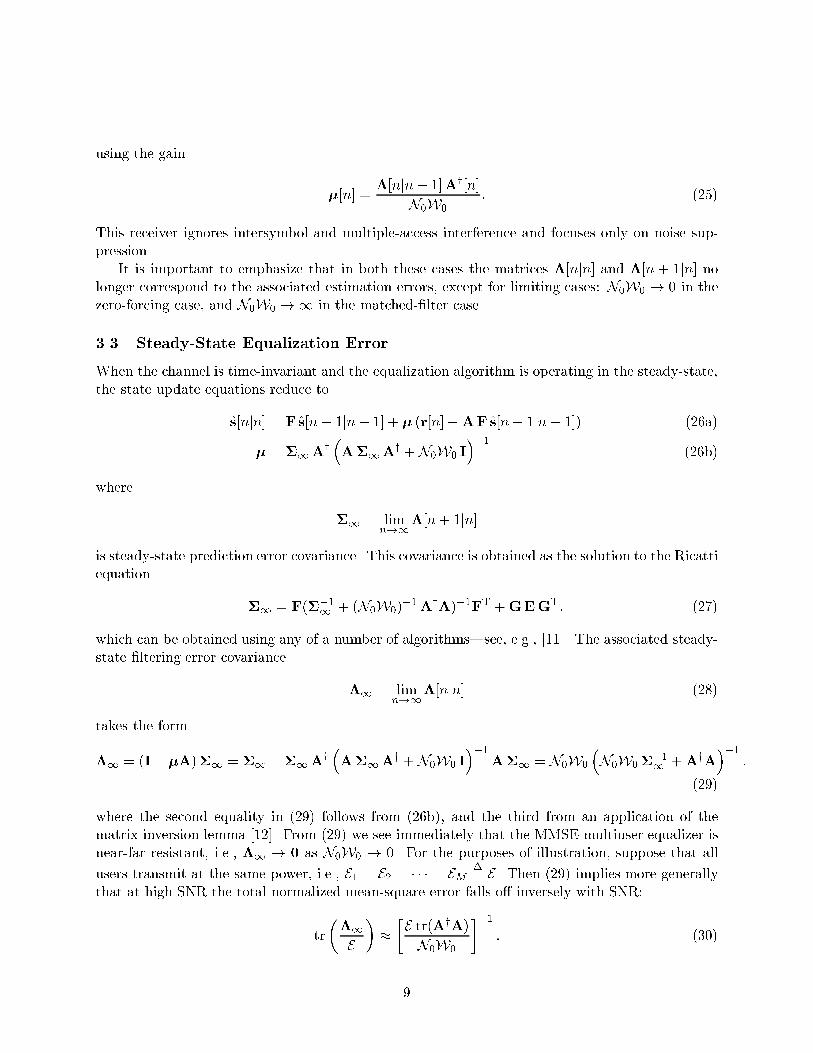
3.3 Steady-State Equalization Error
When the channel is time-invariant and the equalization algorithm is operating in the steady-state,
the state update equations reduce to
s[njn] = F s[n� 1jn� 1] + � (r[n]�AF s[n� 1jn� 1]) (26a)
� = �1Ay
�A�1Ay +N0W0 I
��1(26b)
where
�1 = limn!1
�[n+ 1jn]
is steady-state prediction error covariance. This covariance is obtained as the solution to the Ricatti
equation
�1 = F(��1
1 + (N0W0)�1AyA)�1FT +GEGT; (27)
which can be obtained using any of a number of algorithms|see, e.g., [11]. The associated steady-
state �ltering error covariance
�1 = limn!1
�[njn] (28)
takes the form
�1 = (I� �A)�1 = �1 ��1Ay
�A�1Ay +N0W0 I
��1A�1 = N0W0
�N0W0�
�11 +AyA
��1:
(29)
where the second equality in (29) follows from (26b), and the third from an application of the
matrix inversion lemma [12]. From (29) we see immediately that the MMSE multiuser equalizer is
near-far resistant, i.e., �1 ! 0 as N0W0 ! 0. For the purposes of illustration, suppose that all
users transmit at the same power, i.e., E1 = E2 = � � � = EM�= E . Then (29) implies more generally
that at high SNR the total normalized mean-square error falls o� inversely with SNR:
tr
��1
E
���E tr(AyA)
N0W0
��1: (30)
9

Related expressions for the associated steady-state in�nite-interval smoothing error covariance fol-
low from the multichannel Wiener �ltering results presented in [14].
3.4 Example
As an illustration of the performance of the algorithm, consider a simple example involving reverse-
link transmission from M = 2 users using conventional CDMA signatures of length K = L = 4.
The signatures are orthogonal Hadamard sequences, and the two users transmit with equal power
E . The channels experienced by the two users are time-invariant and have real-valued unit-sample
responses given by
n = 0 1 2 3 4
a0[n] 0.328 0.176 0.011 0.099 -0.196
a1[n] 0.678 0.024 0.719 0.106 0.349
The received powers are therefore quite asymmetric:
EXn
ja0[n]j2 = 0:187E ; EXn
ja1[n]j2 = 1:110E : (31)
The resulting equalization performance is depicted in Fig. 3. The top �gures depict the fre-
quency responses of the channels for each of the two users. The bottom left �gure shows the
combined mean-square equalization error in the signals for the two users after �ltering. The near-
far resistance of the equalization is apparent|there is no interference-limited behavior at high
SNR. The bottom right �gure shows the additional reduction in mean-square equalization error
that can be obtained through the use of smoothing. That there is comparatively little bene�t to
such smoothing beyond a couple lags is a consequence of the comparatively short channel responses
involved.
We conclude this section with a couple of remarks. First, we emphasize that the equalization
structures developed in this portion of the paper apply equally well to both conventional CDMA
systems as well as more recently introduced spread-signature CDMA systems. The primary dif-
ference between the two in terms of equalizer implementation is that the latter class requires an
appropriately larger state space. Second, as mentioned during the development, it is also important
to recognize that the these same equalizer structures can be readily extended for use in narrow-
band or wideband systems employing multiple-element receiver antenna arrays. Finally, it is worth
emphasizing that the algorithms developed above operate at the chip rate of the system. In prac-
tice, baud (symbol) rate algorithms are preferred as they generally have much lower computational
requirements. Related baud-rate state-space equalizer structures are discussed in [13].
3.5 Nonlinear Multiuser Equalization
The simplest means for using the preceding linear multiuser equalizers to obtain (hard) symbol
decisions is to follow the (soft) estimates x[n � kjn] in (21) at the equalizer output with a simple
memoryless decision device, i.e., a slicer. It is this slicer that exploits the property of digital
communication systems that the transmitted symbols are drawn from a discrete alphabet. In
practice, important performance improvements are obtained by exploiting this discrete-alphabet
property in a more integrated manner in the receiver.
10

A highly e�ective means for accomplishing this is to use maximum likelihood sequence detection
to jointly decode all users, generalizing the corresponding approaches of [15] for single-user scenarios
and [16] for multiuser ones. This generalization is discussed in more detail in, e.g., [13]. However,
even when implemented using the associated Viterbi algorithms, the computational complexity
inherent in such receivers is prohibitive in practice.
Another means for exploiting the discrete-alphabet property that requires substantially less
computational complexity is to employ a decision-feedback structure, analogous to an approach
used in single-user decision-feedback equalizers (DFE's).
Using our state-space framework, it is straightforward to develop a natural extension of the
single-user MMSE DFE described in, e.g., [17]. We begin by noting that in the recursion (20a) for
our linear MMSE equalizer, the state estimate is updated via two terms. The �rst is a prediction
of the state based on the state estimate at the previous symbol time. Exploiting a DFE strategy,
the soft state estimates in both terms of (20a) can be replaced with hard symbol decisions that
are typically more accurate, especially at high SNR. With this approach, when, for example, the
symbols are binary xm[n] 2 f�1;+1g, the decisions are generated recursively according to [cf.
(20a)]
�s[njn] = sgn s[njn] = sgn fF�s[n� 1jn� 1] + �[n] (r[n]�A[n]F�s[n� 1jn� 1])g : (32)
where
sgn � =
(+1 � � 0
�1 � < 0(33)
is the associated slicer for this signal set. For other signal constellations, it su�ces to substitute
the appropriate slicer function in (32).
The DFE structure just described is one example of a sequential nonlinear multiuser equaliza-
tion/decoding algorithm that is advantageous when the SNR is at least moderately large. However,
a variety of other types of e�cient nonlinear multiuser equalizer structures can also be developed.
We next explore one such alternative|an e�cient batch-iterative equalization/decoding algo-
rithm based on a successive-cancellation structure.
4 Iterative Multiuser Decoding
Instead of a decision-feedback algorithm in which symbols are decoded in a sequential manner,
with past decisions incorporated to improve the accuracy of future decisions, another approach to
decoding is to apply a multipass decoding algorithm. In the multipass strategy we develop in this
part of the paper, a linear equalizer is applied to the full data, from which tentative hard decisions
are subsequently generated. These tentative decisions are then used to control a subsequent, more
e�ective, processing pass through the data, from which more re�ned hard decisions are generated.
The process repeats until su�ciently accurate hard decisions are obtained.
This strategy can be used e�ectively in multiuser decoding problems involving time-varying
intersymbol interference channels. For the purposes of illustration, we focus on the development
on such techniques for use with spread-signature CDMA transmission formats speci�cally, which
are well-suited for use in time-varying multipath environments [7] [8].
11

In [7], linear receivers were developed for spread-signature CDMA systems. With such receivers,
it was shown that such systems e�ectively transform the multiuser Rayleigh fading channel into a
decoupled set of additive white quasi-Gaussian noise channels. In particular, both the intersymbol
and multiple-access interferences are transformed into a second quasi-Gaussian noise source that is
e�ectively white and uncorrelated with the input data stream. This transformation renders these
interference terms more benign when hard decisions are generated from the soft symbol estimates
using a simple slicer.
As we develop in this part of the paper, further improvements in performance can be achieved
not by transforming but by actually canceling some of the interference through an estimator-
subtracter structure that exploits the discrete-alphabet property of the transmitted streams. The
particular cancellation strategy we develop here is an e�ectively linear complexity algorithm like
the sequential algorithms (and their DFE variants) developed in the �rst part of this paper.
It is worth emphasizing at the outset that the scheme we develop can be viewed as an ef-
�cient generalization of a variety of stripping (successive decoding) strategies proposed for con-
ventional CDMA systems, such as the multistage algorithm developed by Varanasi and Aazhang
[18]. Moreover, in single-user scenarios, where spread-signature CDMA specializes to the class of
spread-response precoding algorithms described in [8] [9], the algorithms we develop specialize to
an e�cient variant of the novel multistage receivers described by Wittneben in [19], into which
useful new insights are obtained.
To simplify our development, we restrict our attention to a special case of the basic system
model described in Section 2. In particular, in addition to focusing on orthogonal spread-signature
CDMA systems with large temporal spreads (i.e., K � L), we also restrict our attention to the
case in which the streams xm[n] consist of speci�cally N -PSK (phase-shift keying) symbols. In our
development, it will also be convenient to adopt a statistical characterization of the fading process.
For this purpose, we consider ergodic Rayleigh fading, so that the am[n; k] for di�erent values of
k are zero-mean, ergodic, complex-valued, circularly-symmetric, jointly Gaussian sequences. We
further restrict our attention to the stationary, uncorrelated scattering scenario, so that the time-
varying frequency response of the channel
Am(!;n] =Xk
am[n; k] e�j! (34)
is stationary in both time n and frequency !. In terms of this frequency response, the SNR at
which the mth user's transmission is received is
1
�m= E
�EmjAmj2N0W0
�: (35)
4.1 Multipass Receivers
As discussed in the preceding section, the decoding algorithm we develop is a batch-iterative al-
gorithm involving successive processing of the received data stream. In describing the algorithm,
we denote the parameters associated with the processing at the lth iteration using a superscript
l. The �rst pass of the algorithm involves applying the linear receiver originally developed for
spread-signature CDMA in [7]. We begin by summarizing its salient characteristics, emphasizing
aspects that will be important in the development of the processing in subsequent passes of the
12

algorithm.
The �rst decoding pass for the mth user's symbol stream is depicted in Fig. 4. Consistent with
our convention, the parameters of all signals and systems involved in this pass have the superscript
1 to re ect that this is the �rst (l = 1) pass of decoding. In this pass, the received data r[n] is �rst
equalized via a linear time-varying �lter with kernel b1m[n; k], producing the sequence
y1m[n] =Xk
b1m[n; k] r[n� k]: (36)
Next, the equalized data y1m[n] demodulated from its signature by correlating with the signature
hm[n] and downsampling at rate L, yielding
x1m[n] =Xk
y1m[k]hm[k � nL]: (37)
Finally, preliminary symbol decisions �x1m[n] are obtained by passing the demodulated data x1m[n]
through a slicer designed for detection of N -PSK symbols in traditional independent additive white
Gaussian noise.
Substituting, in turn, (36) and (3) into (37), it follows that the demodulated stream can be
expressed in the form
x1m[n] = �1m x[n] + v1m[n]: (38)
In (38), �1m is a constant whose value does not depend on the channel realization but is related to
the statistics of the system c1im[n; k] formed from cascading the channel ai[n; k] with the equalizer
b1m[n; k]. In particular, �1m is de�ned via the relation
E�c1mi[n; k]
�= �1m �[k] �[m � i]; (39)
where
c1im[n; k] =Xl
b1m[n; l] ai[n� l; k � l]: (40)
Meanwhile, the term v1m[n] in (38) can be expressed in the form
v1m[n] = u1m[n] +
MXi=1
z1im[n]; (41)
where u1m[n] is a noise term and the z1im[n] are interference terms. In particular,
u1m[n] =Xk
g1m[n; k]w[n � k] (42)
with
g1m[n; k] =Xk1
b1m[k1; k1 � n+ k]hm[k1 � nL]: (43)
13
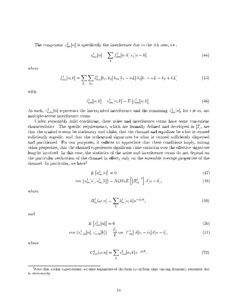
The component z1im[n] is speci�cally the interference due to the ith user, i.e.,
z1im[n] =Xk
f1im[n; k]xi[n� k] (44)
where
f1im[n; k] =Xk1
Xk2
~c1im[k1; k2]hm[k1 � nL]hi[k1 � nL� k2 + kL] (45)
with
~c1im[n; k] = c1im[n; k]�E�c1im[n; k]
�(46)
As such, z1mm[n] represents the intersymbol interference and the remaining z1im[n], for i 6= m, are
multiple-access interference terms.
Under reasonably mild conditions, these noise and interference terms have some convenient
characteristics. The speci�c requirements, which are formally de�ned and developed in [7], are
that the symbol stream be stationary and white, that the channel and equalizer be what is termed
su�ciently ergodic, and that the orthogonal signatures be what is termed su�ciently dispersed
and partitioned. For our purposes, it su�ces to appreciate that these conditions imply, among
other properties, that the channel experiences signi�cant time-variation over the e�ective signature
lengths involved. In this case, the statistics of the noise and interference terms do not depend on
the particular realization of the channel in e�ect, only on the ensemble average properties of the
channel. In particular, we have2
E�u1m[n]
�= 0 (47)
cov�u1m[n]; u
1
m[k]�= N0W0E
h��B1
m
��2i �[n� k]; (48)
where
B1
m(!;n] =Xk
b1m[n; k] e�j!k; (49)
and
E�z1im[n]
�= 0 (50)
cov�z1i1m[n]; z
1
i2m[k]�=EiLvar
�C1
m
��[i1 � i2] �[n� k]; (51)
where
C1
im(!;n] =Xk
c1im[n; k] e�j!k: (52)
2Note that within expectations, we omit arguments of the form (!;n] from time-varying frequency responses due
to stationarity.
14

Due to the underlying model, the noise term u1m[n] and multiple-access interference terms v1im[n],
i 6= m, are obviously uncorrelated with the symbol stream x[n]. However, in this scenario the
intersymbol interference term v1mm[n] is also uncorrelated with x[n] [7]. To see this, it su�ces to
note that as the signature spread K becomes large relative to the channel coherence time, the
coe�cient f1mm[n; 0] in (44) that multiplies xm[n] becomes arbitrarily small (in a mean-square
sense).
Under these conditions, the second-order characteristics of the system up to the input of the
slicer are fully described by the asymptotic signal-to-noise+interference ratio (SNIR)
1m(B1
m) =j�1mj2Em
N0W0Eh��B1
m
��2i+ 1
L
MXi=1
Ei varC1
im
: (53)
Moreover, that the marginal distribution of the interference is asymptotically Gaussian suggests
that the symbol error rate performance of the symbol-by-symbol threshold detector for the N -PSK
stream xm[n] can be reasonably approximated by that given in [20] for the corresponding additive
white Gaussian noise channel, i.e.,
P 1
m � 2Q�sin
� �N
�p2 1m
�; (54)
where
Q (�) =1p2�
Z1
�
e�t2=2 dt:
In practice, this approximation is a remarkably good one as the simulations in [7] con�rm.
From this perspective, it is natural to choose the equalizer so as to maximize the SNIR (53).
Provided the fading is su�ciently slow that
C1
im(!;n] � B1
m(!;n]Ai(!;n]; (55)
the SNIR-maximizing equalizer has a time-varying frequency response given by [7]
B1
m(!;n] /A�m(!;n]
N0W0 +1
L
MXi=1
E l�1i jAi(!;n]j2; (56)
Note that, interestingly, (56) is also the equalizer that would result from a MMSE criterion
(without a causality constraint). In fact, it is possible to verify that for typical forward-link trans-
mission this receiver is e�ectively equivalent to the receiver developed in Section 3.2 provided
su�cient smoothing is accommodated (by, for example, state augmentation) in the estimation in
the latter.
On the reverse-link, the performance of the linear MMSE receiver in Section 3.2 is superior to
that of the �rst stage developed above because the latter imposes a single-user detection structure
rather than equalizing and demodulating all users jointly before making symbol decisions. As a
result, the above system is interference-limited as the results in [7] re ect|the bit-error rate does
15

not go to zero with increasing SNR|making it vulnerable to near-far e�ects [16].
4.1.1 Iterative Interference Estimation-Subtraction
Performance on both forward and reverse links is improved by making use of these preliminary
symbol decisions �x1m[n] in subsequent processing passes of the received data r[n]. The iterative
interference suppression strategy we develop in this section has the following form. Using the
receiver of Fig. 4, we obtain preliminary decisions �x1m[n] for each of the M di�erent symbol streams
at the receiver. In turn, by subsequent processing of these decisions we generate re�ned estimates
z2im[n] of the interference terms in (41). These estimates are then e�ectively subtracted from
an appropriately equalized and demodulated version of the data to produce x2m[n], from which
more reliable symbol decisions �x2m[n] are obtained from the slicer. This process is then repeated,
exploiting the decisions �x2m[n] to generate further re�ned interference estimates z3im[n], etc. A
detailed development follows.
The interference canceler in the lth pass (l � 2) takes the form depicted in Fig. 5. In particular,
we subtract an appropriately constructed estimate zlm[n] of the total intersymbol and multiple-
access interference from the equalized and demodulated version of the data to produce xlm[n], i.e.,
[cf. (36){(37)]
xlm[n] =Xk
ylm[k]hm[k � nL]� zlm[n]; (57)
where
ylm[n] =Xk
blm[n; k] r[n� k]: (58)
It is important to emphasize that in each pass we allow the equalizer blm[n; k], whose time-varying
frequency response we denote by
Blm(!;n] =
Xk
blm[n; k] e�j!k; (59)
to di�er from that used in previous processing passes (including the �rst pass); this exibility will
prove important.
The associated interference estimate zlm[n] used in (57) is a linear combination of estimates of
the constituent interferences, i.e.,
zlm[n] =
MXi=1
�lim zlim[n]; (60)
where the �lim are suitably designed weights. The interference estimates zlim[n] for this lth pass are
in turn generated in the manner depicted in Fig. 6: the symbol decisions from the previous pass are
re-modulated onto the appropriate signature, processed by a noise-free replica of the channel, then
demodulated by a replica of the receiver with the equalizer blm[n; k] used in the canceler (57). The
lower path in Fig. 6 eliminates the symbol of interest from the intersymbol interference estimate,
and obviously doesn't arise in the estimation of multiple-access interference (i 6= m).
16

Analogous to notation we used in the �rst pass, we use clim[n; k] to denote the kernel of the
system formed from the cascade of the equalizer blm[n; k] with the channel corresponding to ai[n; k],
i.e.,
clim[n; k] =Xk1
blm[n; k1] ai[n� k1; k � k1]; (61)
and use
C lim(!;n] =
Xk
clim[n; k] e�j!k (62)
to denote associated time-varying frequency response. The parameter �lm in the lower path of
Fig. 6 is related to the mean of this cascade channel. In particular, it is de�ned via the relation
EhC lim(!;n]
i= �lm �[m� i]: (63)
As a result, the interference estimate can be expressed in the form [cf. (44){(46)]
zlim[n] =Xk
f lim[n; k] �xl�1i [n� k]; (64)
where
f lim[n; k] =Xk1
Xk2
~clim[k1; k2]hm[k1 � nL]hi[k1 � nL� k2 + kL] (65)
with
~clim[n; k] = clim[n; k]�Ehclim[n; k]
i: (66)
With the above interference estimation-subtraction structure, the input to the subsequent slicer
in Fig. 5 can be expressed in the form
xlm[n] = �lm xm[n] + vlm[n]: (67)
Analogous to (41){(43), the additive distortion vlm[n] in (67) can be expressed in the form
vlm[n] = ulm[n] +
MXi=1
~zlim[n]; (68)
where ulm[n] is the noise term
ulm[n] =Xk
glm[n; k]w[n � k] (69)
17

with
glm[n; k] =Xk1
blm[k1; k1 � n+ k]hm[k1 � nL]; (70)
and where the ~zlim[n] are residual interference terms
~zlim[n] = zlim[n]� �lim zlim[n] (71)
in which [cf. (64)]
zlim[n] =Xk
f lim[n; k]xi[n� k]: (72)
4.2 Receiver Optimization
Not surprisingly, the choice of both the equalizer coe�cients blm[n; k] and canceler weights �lim in
each pass l of receiver processing strongly a�ect the quality and convergence characteristics of the
symbol decisions produced in each pass. One rather natural way to select these parameters is so
that in each pass the slicer input SNIR is maximized.
Assuming, as was true in the �rst processing pass, that for any particular realization of the
channel the noise terms ulm[n] and residual interference terms ~zlim[n] in (68) are each asymptotically
zero-mean, stationary, white, uncorrelated with one another, and uncorrelated with the symbol
stream xm[n], then the SNIR at the input to the slicer in the lth processing pass can be expressed
in the form
lm
�blm; �
l1m; �
l2m; : : : ; �
lMm
�=
���lm��2 Emvarulm +
MXi=1
var zlim
: (73)
It then remains to express the quantities in (73) in terms of the parameters to be optimized.
Expressing the �rst denominator term in (73) in the desired form is straightforward in this
scenario:
varulm[n] = N0W0E
����Blm
���2� : (74)
To obtain the remaining denominator terms, we assume that
var zlim[n] � var zlim[n] = EiXk
���f lim[n; k]���2 = EiLvarC l
m; (75)
which is valid at least at high SNR, and that the correlation between the actual symbols and
intermediate decisions is one of the form
Ehx�i [n] �x
lm[k]
i� �lm Em �[n� k] �[i �m]; (76)
18

where the �lm are correlation coe�cients that can be calculated. In this case, using the approxima-
tions (75) and (76) with (64) and (72) in (71), we obtain
var ~zlimvar zlim
� 1 +����lim���2 � 2Re
n�lim�
l�1i
o= 1 +
����l�1i
���2 + ����lim � ��l�1i
�����2 (77)
In turn, substituting the right-hand side of (75) into (77), it is straightforward to verify that
var ~zlim �~E liLvarC l
im; (78)
where
~E l�1i = Ei�1�
����l�1i
���2� (79)
with equality if and only if
�lim =��l�1i
��: (80)
Hence, the maximum achievable SNIR is obtained when the weights �lim are chosen according to
(80).
Using (78), (74), and (63) in (73) yields an SNIR in terms of the optimized weights (80) of the
form
lm(Blm) =
��E �C lim
���2 EmN0W0E
����Blm
���2�+ 1
L
MXi=1
~E l�1i varC lim
: (81)
Note that (53) can be viewed as a special case of (81) when we adopt the convention that �0m�= 0.
Finally, assuming su�ciently slow fading that in each pass l the approximation
C lim(!;n] � Bl
m(!;n]Ai(!;n] (82)
is valid, then (81) can then be further expanded as
lm(Blm) =
��E �AmB
lm
���2 EmN0W0E
����Blm
���2�+ 1
L
MXi=1
~E l�1i varhAiB
li
i : (83)
In this form, it is straightforward to optimize the SNIR lm over the choice of equalizer frequency
response Blm(!;n]. We consider forward- and reverse-link scenarios separately.
In the forward-link scenario, all xm[n] pass through the same channel [see (11)]. As a result
we can drop the subscripts from our notation for the channel, equalizer, and cascade frequency
responses, using, respectively, A(!;n], Bl(!;n], and C l(!;n] for all m. In this case, (83) specializes
19

to
lm(Blm) =
��E �ABl
���2 EmN0W0E
����Bl���2�+ �E l�1 var
hABl
i ; (84)
where
�E l = 1
L
MXi=1
~E li : (85)
With lm in the form (84), a special case of Lemmas 1 and 2 from [7] can be applied to obtain
that
lm(Bl) �
�� l�1
�m
�1
�� l�1 exp(�� l�1)E1(�� l�1)� 1
�(86)
with equality if and only if
Bl(!;n] / A�m(!;n]
N0W0 + �E l�1jA(!;n]j2: (87)
In (86),
1�� l
= E
��E ljAj2N0W0
�=
1
L
MXi=1
1����li��2�i
; (88)
with �m as given in (35), and E1(�) denotes the exponential integral, i.e.,
E1(�) =
Z1
�
e�t
tdt:
For reverse-link transmission, the general cases of Lemmas 1 and 2 from [7] can be applied to
show that (83) satis�es
lm(Blm) �
L
1�����l�1m
���2�
1
�l�1m
� 1
�(89)
with equality if and only if
Blm(!;n] /
A�m(!;n]
N0W0 +1
L
MXi=1
~E l�1i jAi(!;n]j2: (90)
20

In (89),
�lm =M � 1
M+
(L~� lm)M
M !
"(�1)M+1eL
~�lmE1(L~�
lm) +
M�2Xk=0
(�1)M�k k!
(L~� lm)k+1
#(91)
with
1
~� lm= E
"~E lm jAmj2
N0W0
#=
1����lm��2�m
; (92)
where again �m is as given in (35).
Hence (87) and (90) are the optimum equalizers for the forward and reverse links, respectively,
and the associated slicer input SNIR's that are attained with these equalizers are given by the
corresponding right-hand sides of (86) and (89). Implementing each of these equalizers requires
explicit knowledge of the set of correlation coe�cients �lm that characterize the quality of the
symbol decisions produced at the output of the slicer in each processing pass. Conveniently, these
coe�cients can be computed sequentially using an e�cient recursive algorithm, as we now develop.
4.3 Weight and Performance Calculation Recursion
To obtain a suitable recursion, we �rst express the desired correlation coe�cients �lm in terms
of the symbol error probability P lm at the output of the corresponding slicer. To complete the
recursion, we then determine an expression for the symbol error probability P lm as a function of the
corresponding correlation coe�cients �l�1m associated with the symbol decisions from the previous
processing pass.
We note in advance that this not only yields a recursive algorithm for computing the correlation
coe�cients, but also one for predicting the error probabilities of the symbol decisions generated in
each pass of the algorithm. This information is useful both in determining asymptotic performance
limits and in estimating a priori the number of decoding iterations required in practice, as we will
discuss later.
To express the coe�cient �lm in terms of P lm, we begin by writing the error at the output of the
associated slicer in the form
elm[n] = �xlm[n]� xm[n]; (93)
and note that when N > 2 and xm[n] =pEm, we have the approximation
Pr
�elm[n]pEm
= �2 sin2� �N
�+ j2 sin
� �N
�cos
� �N
��=
Pr
�elm[n]pEm
= �2 sin2� �N
�� j2 sin
� �N
�cos
� �N
��� P l
m
2: (94)
Thus, exploiting, in turn, symmetry and (94) we obtain
Ehx�m[n] e
lm[n]
i= E
hx�m[n] e
lm[n]
��� xm[n] =pEmi� �2 sin2
� �N
�EmP l
m: (95)
21

Finally, using (95) with (76), we obtain, for l � 1, our desired expression
�lm =Ehjxm[n]j2
i+E
�x�m[n] e
lm[n]
�Em
� 1� 2 sin2� �N
�EmP l
m: (96)
Note that (96) implies that, as we would expect, for constellations with such symmetry the corre-
lation coe�cient is real: �lm =��lm��.
It is similarly straightforward to develop an expression for P lm in terms of �l�1m . We begin by
observing that we can express P lm in terms of lm using an approximation analogous to that used
to obtain (54). In particular, by neglecting any statistical dependence between vlm[n] and x[n] in
(67), and treating vlm[n] as a stationary, white, Gaussian process, the N -PSK symbol error rate for
the decisions produced by the slicer can be expressed as
P lm � 2Q
�sin
� �N
�q2 lm
�; (97)
Finally, to complete the mapping from �l�1m to P lm, we substitute the right-hand side of either
(86) or (89) into (97), depending on whether the scenario of interest is forward- or reverse-link
transmission, respectively.
We conclude this section with a summary of the recursion for determining the correlation
coe�cients required in the equalizer and for predicting the symbol error rate performance as a
function of the number of iterations used:
1. Set �0m = 0 and let l = 1.
2. For each m, compute the SNIR lm at the slicer input on the lth decoding pass from the
correlation coe�cients �l�1m and channel SNR via the right-hand side of either (86) or (89)
for forward- or reverse-link transmission, respectively. Compute the symbol error probability
P lm for the slicer output from the slicer input SNIR lm via (97).
3. For eachm, from the symbol error probabilitiesP lm produced in Step 2 compute the correlation
coe�cients �lm. via (96).
4. Increment l and go to step 2.
4.4 Performance Characteristics
In this section, we develop some properties of the performance predictions, and compare these
predictions to the results of Monte Carlo experiments. For the purposes of illustration, in both
forward- and reverse-link transmission we restrict our attention to the scenario in which �m = � for
all m, in which case we may omit the subscripts from our notation for the correlation coe�cients,
SNIR's, and symbol error probabilities|yielding, respectively, �l, l, and P l. Note that on the
reverse link, this corresponds to the case in which power control is employed.
The characteristics of the performance predictions are best understood graphically, as we now
illustrate in the case of the forward link with QPSK (N = 4), M = 8 users, no excess bandwidth
(L =M), and maximally-spread signatures.
22

For a given received SNR level 1=�, the relationship between �l�1 and P l corresponding to Step
2 of the above procedure is one of the form
P l = F (�; �l�1); (98)
where the function F (�; �) has the property that it is decreasing with both SNR 1=� and correlation
�l, as can be veri�ed by substituting the right-hand side of (86) into (97). The solid curves of Fig. 7
show the function F (�; �) plotted as a function of 1=(1 � �) on a log-log scale for several values of
1=�.
Meanwhile, the mapping (96) between P l and �l in Step 3 takes the form
P l = G(�l) (99)
where the function G(�) is also decreasing with �l. The function G(�) is linear as a function 1=(1��)when plotted on a log-log scale, as depicted in Fig. 7 via the dashed line.
For a given operating SNR, the progression of symbol error probabilities and correlation coef-
�cients for successive processing passes is obtained by iterating between the associated solid curve
and the dashed line in Fig. 7. In particular, the value of the solid curve at � = 0 determines the
symbol error probability P 1 at the slicer output after the �rst stage of processing. The correlation
coe�cient �1 is then obtained as the value of � at which the dashed line takes on the value P 1. The
symbol error probability P 2 after the second stage is then the height of the solid curve at � = �1,
and the process repeats.
Graphically, this locus of operating points is obtained by a moving horizontally from the solid
curve to the dashed curve, and vertically from the dashed curve back down to the solid curve. This
corresponds to a descending a staircase where there is one such step for each processing pass. In
Fig. 7, the sequence of operating points obtained in this manner are depicted via the � symbols
along each solid curve.
From this analysis, it is apparent that the sequence of symbol error probabilities P 1; P 2; : : :
obtained by this iterative algorithm is both monotonically decreasing and convergent. This implies
that additional processing passes are always bene�cial in terms of reducing error rate performance.
The steady-state symbol error probability P1 for an SNR of 1=� follows immediately as the unique
solution to the equation
P1 = F (�;G�1(P1)) (100)
where G�1(�) is the inverse of G(�), i.e., [cf. (99)], �l = G�1(P l). This steady-state error probability
corresponds to the intersection of the dashed line and appropriate solid curve in Fig. 7.
As Fig. 7 re ects, much of the steady-state performance is achieved with relatively few iterations,
after which there are strongly diminishing returns to additional processing passes. And while these
performance characteristics are based on theoretical predictions, in practice they appear to be
quite accurate for this forward-link case. For example, the sequence of experimentally obtained
operating points are identi�ed by the � symbols in Fig. 7. In these experiments, symbol error rates
were measured empirically, and the appropriate correlation coe�cients were computed numerically
as sample-averages from streams generated in simulations.
The asymptotic e�ciency of the iterative receiver can also be inferred from Fig. 7. To see this,
note from (86) and (89) that in both forward- and reverse-link scenarios l+1m ! 1=�m when �li ! 1
23

for all i, which when substituted into (97) yields the performance of the classical additive white
Gaussian noise channel. Thus, each of the solid curves in Fig. 7 approach this performance level
from above with increasing �. Since the dashed line intersects the solid curve at larger values of �
as the SNR 1=� increases, this implies that the performance of the classical additive white Gaussian
noise channel is approached at high SNR.
This asymptotically perfect interference cancellation behavior is more directly apparent in Fig. 8,
where error rate is plotted as a function of SNR for di�erent numbers of receiver processing passes.
As we also see from this �gure, on the order of only (l � 5) iterations of the decoding algorithm
are required to converge to typical target bit error rates. This is signi�cant since the amount of
computation is directly proportional to the number of iterations required. We emphasize that the
complexity is substantially lower than maximum likelihood sequence detection.
Performance predictions of the type developed above can be obtained in a similar manner for
reverse link scenarios. As an illustration, Fig. 9 depicts performance as a function of the number
of decoding iterations in a power-controlled system with M = 2 users, no bandwidth expansion
(L = M), and QPSK (N = 4) symbols. The corresponding plots of predicted performance as
a function of SNR are shown in Fig. 10. As these �gures re ect, a modest number of iterations
generally su�ces for convergence in this reverse-link scenario as well. It is important to point out,
however, that when large numbers of users are involved, the predictions tend to be somewhat overly
optimistic even at high SNR. This suggests that some of the approximations used in the system
optimization and analysis in preceding sections may be less appropriate in such cases.
5 Concluding Remarks
The algorithms developed in this paper are representative of several emerging next-generation re-
ceiver structures for CDMA systems. However, while promising, many issues remain to be explored
and addressed before receivers of this type can be considered for practical implementation.
In terms of the iterative decoding, one obviously important area for further research involves
further improving the performance of the multipass receiver through algorithmic enhancements and
developing more accurate predictions of the resulting performance, particularly on the reverse-link
with typical numbers of users.
Other issues that warrant further investigation include robustness of the iterative decoding
algorithm. Preliminary simulations suggest that the performance achieved with each pass is quite
sensitive to precise speci�cation of the correlation coe�cients. Quantifying this sensitivity and
developing versions of the algorithm that are inherently more robust to correlation coe�cient
modeling and quantization errors is an important area for further work.
In addition, exploring the impact of using the channel estimates available in practice in the
equalizer construction rather than perfect channel knowledge is important in terms of practical
application. From this perspective, extensions of the kinds of robust equalization techniques de-
veloped in [21] for spread-response precoding systems are likely to prove valuable. Also of interest
would be blind variants of the algorithms in this paper that don't require training data or pilot
tones. The recent work of, among others, Poor and Wang [22] has shown that blind algorithms for
such problems are feasible.
As suggested in the introduction, both the batch-iterative and earlier sequential decision-
feedback decoding algorithms developed in this paper can, in principle, be used directly in the
receivers of multiuser systems exploiting transmitter antenna diversity|such as those developed
24

in [10]|to enhance performance. As such, exploring their use in this context also warrants further
research.
Finally, important new insights are likely to arise from an in-depth exploration the relationships
between the two classes of decoding algorithms developed in this paper. More generally, a great
deal of interesting and important research remains to be done on interrelating the wide range of
algorithms currently under development in the community within this active and exciting area of
research.
References
[1] R. Lupas and S. Verd�u, \Linear multiuser detectors for synchronous code-division multiple-
access channels," IEEE Trans. Inform. Theory, vol. 35, pp. 123{136, Jan. 1989.
[2] R. Lupas and S. Verd�u, \Near-far resistance of multiuser detectors in asynchronous channels,"
IEEE Trans. Commun., vol. 38, pp. 496{508, Apr. 1990.
[3] U. Madhow and M. L. Honig, \MMSE interference suppression for direct-sequence spread-
spectrum CDMA," IEEE Trans. Commun., vol. 42, pp. 3178{3188, Dec. 1994.
[4] M. Honig, U. Madhow, and S. Verd�u, \Blind adaptive multiuser detection," IEEE Trans.
Inform. Theory, vol. 41, pp. 944{960, July 1995.
[5] M. L. Honig and H. V. Poor, \Adaptive interference suppression in wireless systems," in
Wireless Communications: Signal Processing Perspectives (H. V. Poor and G. W. Wornell,
eds.), ch. 2, Upper Saddle River, NJ: Prentice-Hall, 1998.
[6] G. W. Wornell, \E�cient linear diversity techniques for fading channels," inWireless Commu-
nications: Signal Processing Perspectives (H. V. Poor and G. W. Wornell, eds.), ch. 1, Upper
Saddle River, NJ: Prentice-Hall, 1998.
[7] G. W. Wornell, \Spread-signature CDMA: E�cient multiuser communication in the presence
of fading," IEEE Trans. Inform. Theory, vol. 41, pp. 1418{1438, Sept. 1995.
[8] G. W. Wornell, \Emerging applications of multirate systems and wavelets in digital commu-
nications," Proc. IEEE, vol. 84, Apr. 1996.
[9] G. W. Wornell, \Spread-response precoding for communication over fading channels," IEEE
Trans. Inform. Theory, vol. 42, pp. 488{501, Mar. 1996.
[10] G. W. Wornell and M. D. Trott, \E�cient signal processing techniques for exploiting transmit
diversity on fading channels," IEEE Trans. Signal Processing, vol. 45, pp. 191{205, Jan. 1997.
[11] B. D. O. Anderson and J. B. Moore, Optimal Filtering. Englewood Cli�s, NJ: Prentice-Hall,
1979.
[12] S. Haykin, Adaptive Filter Theory. Englewood Cli�s, NJ: Prentice-Hall, 1986.
25

[13] H. C. Papadopoulos, \Equalization for multiuser wireless systems," in Wireless Communi-
cations: Signal Processing Perspectives (H. V. Poor and G. W. Wornell, eds.), ch. 3, Upper
Saddle River, NJ: Prentice-Hall, 1998.
[14] A. Duel-Hallen, \Equalizers for multiple input/multiple output channels and PAM systems
with cyclostationary input sequences," IEEE J. Select. Areas Commun., vol. 10, pp. 630{639,
Apr. 1992.
[15] G. D. Forney, Jr., \Maximum-likelihood sequence estimation of digital sequences in the pres-
ence of intersymbol interference," IEEE Trans. Inform. Theory, vol. IT-18, pp. 363{378, May
1972.
[16] S. Verd�u, \Minimum probability of error for asynchronous Gaussian multiple-access channels,"
IEEE Trans. Inform. Theory, vol. IT-32, pp. 85{96, Jan. 1986.
[17] J. M. Cio�, G. P. Dudevoir, M. V. Eyuboglu, and G. D. Forney, Jr., \MMSE decision-feedback
equalizers and coding|Parts I and II," IEEE Trans. Commun., vol. 43, pp. 2582{2604, Oct.
1995.
[18] M. K. Varanasi and B. Aazhang, \Multistage detection in asynchronous code-division multiple-
access communications," IEEE Trans. Commun., vol. 38, pp. 509{519, Apr. 1990.
[19] A. Wittneben, \A novel bandwidth e�cient analog coding/decoding scheme for data trans-
mission over fading channels," in Proc. IEEE GLOBECOM, 1994.
[20] J. G. Proakis, Digital Communications. New York, NY: McGraw-Hill, 2nd ed., 1989.
[21] J. N. Laneman, \Channel estimation and equalization for spread-response precoding systems
in fading environments," Master's thesis, M. I. T., Cambridge, MA, June 1997.
[22] H. V. Poor and X. Wang, \Blind adaptive joint suppression of MAI and ISI in CDMA chan-
nels," in Proc. Asilomar Conf. Signals, Systems, Computers, 1997.
26

↑ Lx [n]m h [n]m y [n]m
Figure 1: Modulation of the the mth user's coded symbol stream xm[n] onto a signature sequence
hm[n] for transmission.
a [n;k]
a [n;k]My [n]M
⋅ ⋅ ⋅
+
w[n]
r[n]
y [n]1
y [n]2 a [n;k]2
1
Figure 2: General multiuser intersymbol interference channel model, where am[n] denotes the unit-
sample response corresponding to the mth user.
27

0 5 10 150
0.1
0.2
0.3
0.4
0.5
0.6
0.7
0.8
0.9
1
Lag
Ga
in d
B
Smoothing Gain SNR = 10
0 5 10 15 20 25 30 35 40 45 50−45
−40
−35
−30
−25
−20
−15
−10
−5
0
5
Es/No dB
MS
E d
B
Mean−Square Symbol Estimation Error
0 0.1 0.2 0.3 0.4 0.5 0.6 0.7 0.8 0.9 10.1
0.2
0.3
0.4
0.5
0.6
0.7
Normalized Frequency
Ga
in
Frequency Response of Channel 1
0 0.1 0.2 0.3 0.4 0.5 0.6 0.7 0.8 0.9 10
0.2
0.4
0.6
0.8
1
1.2
1.4
1.6
1.8
2
Normalized Frequency
Ga
in
Frequency Response of Channel 2
Figure 3: Performance of the linear MMSE multiuser equalizer in a M = 2 user time-invariant
scenario.
y [n]1m
ˆr[n] h [-n]mb [n;k]1
m ↓ Lx [n]1m
ˆx [n]1m
ˇ
Figure 4: Processing in the �rst pass of the iterative receiver.
28

z [n]
r[n] h [-n]mb [n;k]lm ↓ L
x [n]lm
ˆx [n]lm
ˇl
my [n]ˆ
⊕
lm
ˆ
+
−
Figure 5: Interference cancellation in the lth decoding pass.
x [n]l-1 m
ˇ h [n] i ⊕ limz [n]
+
−↑ L ↓ Lh [-n]m
limc [n;k]
⊗
µ δ[i-m]ml
Figure 6: Interference estimation for the lth decoding pass.
29

100
101
102
103
104
105
10−5
10−4
10−3
10−2
10−1
100
1/(1−ρ)
Sym
bol E
rror
Pro
babi
lity
Figure 7: Iterative receiver performance on the forward link. The successively lower solid curves
plot QPSK symbol error rate as a function of the correlation coe�cient � for SNRs of 7, 10, and 12
dB. Along each curve, circles (�) identify the theoretically predicted decreasing error rates achieved
with l = 1; 2; : : : decoding passes, and the intersections with the dashed line are the steady-state
values (l!1). The associated experimentally obtained values are depicted using squares (2).
30

0 5 10 1510
−4
10−3
10−2
10−1
100
SNR (dB/symbol)
Sym
bol E
rror
Pro
babi
lity
Figure 8: Iterative receiver performance as a function of SNR on the forward link. The successively
lower solid curves depict the symbol error rate as a function of SNR for 1, 2, 3, 5, and 1 decoding
passes for QPSK transmission. The dashed curve is the symbol error rate performance on a classical
additive white Gaussian noise channel with the corresponding SNR.
31

2 4 6 8 10 12 1410
−4
10−3
10−2
10−1
100
Number of Iterations
Sym
bol E
rror
Pro
babi
lity
Figure 9: Iterative receiver performance on the reverse link, with M = 2 users and power control.
The successively lower curves formed from �'s connected by dashed lines depict predicted QPSK
symbol error rate as a function of the number of decoding passes, for SNRs of 5, 9, 11, and
14 dB. The corresponding curves formed from 2's connected by solid lines are the experimental
measurements.
32

0 5 10 1510
−4
10−3
10−2
10−1
100
SNR (dB/symbol)
Sym
bol E
rror
Pro
babi
lity
Figure 10: Iterative receiver performance as a function of SNR on the reverse link, with M = 2
users and power control. The successively lower solid curves formed from measurements (shown
as 2's) depict the QPSK symbol error rate as a function of SNR for 1; 2; : : : ; 10, and 1 decoding
passes. The dashed curve is the corresponding AWGN channel performance.
33