adaptive beam-forming with interference suppression and
TRANSCRIPT
1
Abstract— Adaptive space-time signal processing comprising
interference suppression and multi-user detection in a CDMA
Mobile Satellite System (MSS) environment is presented.
Optimum beam-forming, based on a Minimum Mean-Squared
Error (MMSE) performance index, is used to maximize the
signal-to-noise plus interference ratio of MSS links in an
environment of significant terrestrial reuse of the satellite service
link frequencies by Ancillary Terrestrial Components (ATCs).
The technique substantially mitigates both ATC-induced co-
channel interference and Multiple-Access Interference (MAI).
At the satellite gateway, a pilot-based MMSE algorithm is used to
adaptively form an optimum return-channel beam for each user
by processing the raw antenna feed element signals provided to
the satellite gateway by a satellite return feeder link. Following
beam-forming, pilot signals are used to estimate the multi-user
channels. The proposed Sequential ATC and MAI Interference
Canceller (SAMIC) algorithm takes advantage of a priori known
pilot signal information and invokes preliminary decisions to
sequentially perform interference suppression followed by multi-
user detection. The performance of the SAMIC algorithm is
illustrated by simulation of a multi-beam geo-stationary satellite
system containing a wide deployment of ATC over 50 major
markets across the Continental United States (CONUS).
Keywords—Adaptive Beamforming, CDMA, Mobile Satellite
System, Ancillary Terrestrial Component, Interference
Cancellation, Multi-User Detection
I. INTRODUCTION
The terrestrial reuse of satellite-band service-link frequencies is a
relatively new concept that has been proposed to, and accepted by,
the Federal Communications Commission (FCC)1 and Industry
Canada (IC).2 In this paper, we analyze a hybrid system that is
based on this new spectrally-efficient concept. The “Ancillary
Terrestrial Component” (ATC) network reuses the satellite-band
service link frequencies to provide reliable communications in
populous areas, where satellite connectivity is unreliable, while the
space segment serves rural and other non-populous areas. As a
consequence, uplink co-channel interference to satellite links may be
present and may become harmful, under certain conditions where
there is insufficient discrimination between co-channel satellite and
terrestrial links. In this paper we study the impact on a state-of-the-
1 See Report and Order and Notice of Proposed Rulemaking, FCC 03-15,
Flexibility for Delivery of Communications by Mobile Satellite Service
Providers in the 2 GHz Band, the L-Band, and the 1.6/2.4 Bands, IB Docket
No. 01-185, Adopted: January 29, 2003, Released: February 10, 2003.
2 See Industry Canada, Spectrum Management and Telecommunications
Policy DGTP-006-04 “Spectrum and Licensing Policy to Permit Ancillary
Terrestrial Mobile Services as Part of Mobile-Satellite Service Offerings,”
May 2004.
art Mobile Satellite System (MSS) of an ATC Network (ATN) that is
widely deployed over 50 major markets spanning the Continental
United States (CONUS).3 The air interface communications protocol
assumed for the system (for both the satellite and ATC service links)
is cdma2000 1XRTT in accordance with the cdma2000-1XRTT
specifications [1]. While the terrestrial part of the system (the ATC
links) will experience interference in accordance with the
conventional (well-understood) propagation impairments, the
satellite part of the system (the satellite links) will, in general,
experience additional ATC-induced co-channel interference. This
additional ATC-induced interference on top of the conventional
inter-beam and intra-beam Multiple-Access Interference (MAI)
presents a new challenge for the CDMA-based hybrid satellite
system.
In conventional third generation CDMA systems, the major
impediments to signal detection are multipath fading and MAI.
While the multipath fading can be effectively combated by rake
matched filtering, through coherently combining of resolvable
multipath replicas of the desired signal, the problem of MAI can be
resolved with multi-user detection techniques [2][3]. Rake matched
filtering is a time-domain signal processing technique, as is multi-
user detection. To further improve receiver performance, space-
domain processing techniques have been explored by using multiple
antennas at the base station receiver. The gain due to space-domain
processing is achieved by coherently combining the desired signals
from multiple antennas. Combining space-domain techniques with
time domain techniques, (space-time detection) [4], promises to
significantly improve the capacity of CDMA systems. For the MSS
environment, no known published work has postulated space-time
detection to mitigate both MAI and strong co-channel interference.
Modern MSS satellites use multiple receiving antenna feed
elements to form a plurality of service area spot-beams (or cells).
Satellite systems such as that of Thuraya and Inmarsat-4, for
example, process the signals provided by the satellite’s receiving
antenna feed elements at the satellite, by applying complex weights
and then forming linear combinations thereof, to form a plurality of
service area beams (cells). In contrast, the received antenna feed
element signals may be transported to a satellite gateway, via one or
more satellite feeder links, and processed there in accordance with
one or more performance criteria. The present work, based on this
approach, uses the satellite’s antenna feed element signals to first
perform adaptive beam-forming (in order to mitigate the ATN-
induced interference and other interference) and then, operating on
the reduced-interference signals, removes intra-beam MAI by
resorting to multi-user detection. The space processing (beam-
forming) is performed ahead of the time processing because it may
be difficult to perform effective signal detection without first
stripping-away the intra-system ATN-induced interference, which
may be strong. The adaptive beam-former uses a priori knowledge
3 The term ATC denotes the part of the overall ancillary terrestrial network
that serves a specific market/city. The term ATN relates to the entire ancillary
terrestrial network over the entire footprint of the satellite.
Adaptive Beam-Forming with Interference Suppression and Multi-User
Detection in Satellite Systems with Terrestrial Reuse of Frequencies
Dunmin Zheng and Peter D. Karabinis
Mobile Satellite Ventures, LP
10802 Parkridge Blvd., Reston, VA 20191, USA
2
of the pilot signal of the cdma2000 reverse link waveform.
Following the beam-forming, pilot signals are used to estimate multi-
user channels for intra-beam MAI cancellation.
II. SYSTEM MODEL
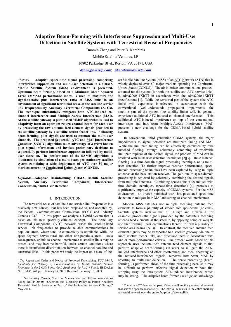
The satellite forward service links (space-to-earth) are assumed to
exist over fixed spot beams. Each of the fixed forward link spot
beams is analogous to a terrestrial cell though significantly larger. A
three-cell frequency reuse cluster size is assumed for the forward
satellite links, as depicted in Fig. 1. A number of ATC base stations
(ancillary terrestrial cells) may exist within a satellite spot beam.
The ATC base stations and the terminals thereof use frequencies that
are allocated to adjacent satellite spot beams in order to maximize the
isolation between the terrestrial and satellite reuse of the MSS
spectrum. Fig. 1 also shows “exclusion” zones (dotted circles)
inside of which the frequencies used for MSS are not made available
to the ATC contained therein. Fig. 1 also illustrates the typically
larger geographic footprints of the return-link satellite antenna feed
elements (relative to the smaller footprints of the forward-link
satellite spot-beams). The signals provided to the satellite gateway
by such return-link antenna feed elements are used to perform
optimum adaptive (return-link) signal processing comprising beam-
forming, interference cancellation, channel estimation and multi-user
detection.
The satellite channel is assumed to be Rician flat-fading. For the
kth return-link satellite user, the vector channel impulse response
across L antenna feed elements may be written as
)()t(),()t,( kkkkkk ah (1)
where Lx1
CT
kkL,kkk1,kkkk )],(a),,(a[),(a (2)
is the satellite return-link antenna feed element complex response
vector for the kth user located at elevation angle k and azimuth angle
k. The quantity
)}tf2(jexp{)t( kkkk (3)
is the return-link path gain for the kth user, fk is the Doppler shift and
k is a phase shift. The quantity k in (1) represents a time delay of
the kth user. Assuming K co-beam users and the channel vector
Figure 1. Satellite Forward-Link Beams and ATC Frequency Reuse
impulse response identified above, the data vector over the output of
L antenna feed elements can be expressed as
)t()t(vg),(
)]t(pg)t(),()t(s)t(bg)t(),([
)t()t(vg),()t,()]t(pg)t(s)t(bg[)t(
N
1n
nnnnn
kkpkkkkkk
K
1k
kkskkkk
K
1k
N
1n
nnnnnkkpkks
na
aa
nahyLx1C
(4)
where bk(t) and sk(t) denote the information bit and spreading
sequence, respectively, of the kth user with M chips/bit; pk(t) is the
pilot chip sequence of the kth user; and gs and gp denote amplitudes of
the traffic data signal and the pilot signal, respectively (assumed the
same for all K users). The quantity vn(t) denotes the aggregate
interference signal generated by the nth ATC service area/city
modeled as complex Gaussian noise, and gn is associated amplitude.
Finally, n(t) Lx1C represents additive complex Gaussian noise.
Assuming matched filtering by correlating the signal that is
received by the lth antenna feed element with the information and
pilot spreading codes, an M-vector output signal corresponding to the
lth antenna feed element can be expressed as
Mx1
llll C
K
1k
N
1n
nnnn,nkpkkskkk,k g),(a)]gbg(),(a[ nvpsy
(5)
where sk and pk denote the spreading code M-vectors corresponding
to sk(t- k) and pk(t- k) respectively. The spreading codes for the
signal and pilot are normalized and are assumed orthogonal
1,1 kk ps ; 0, kk ps ; nv is the complex M-vector
Gaussian noise corresponding to the nth ATC service area, and ln is
a complex M-vector corresponding to the Gaussian noise at the lth
antenna feed element.
By introducing matrix notation, we may rewrite Equation (5) as:
lllll n1AV1 APb ASy ggg nN
(n)
pKs (6)
where MxKC][ K21 sssS data spreading code matrix;
KxK
lll C}),(a),(a{diag KKK,K111,1A lth feed
element/channel matrix; Kx1R
T
K1 ]bb[b K-vector of data
bits; MxKC][ K21 pppP pilot spreading code matrix;
ux1R
T
u ]11[1 u-vector of ones;
MxNC][ N21 vvvV ATC interference matrix; and
NxN
lll C)},(a),(a{diag NN,N11,1
(n)A lth feed element
matrix for N ATCs. The noise vector Mx1
l Cn is a zero-mean
complex Gaussian vector. The ATC interference vector Mx1Cnv
(for the nth ATC, N2,1,n ) is modeled as a zero-mean
complex Gaussian vector, and gn is assumed the same for all ATCs.
Given the above formulation, the problem of interest is to estimate
the information ),2,1k(bk K from the observables
).,2,1( Llly
Spot-beam
(forward link)x
x
xx x
xx
x
xx
x
xx
x
x
x
xx
xx
x
x
x
x
xxx
xx
xx
x
xx
x
x
Desired Satellite User
xx
x
xxx
x
ATC Cluster
Exclusive Zone
(inside circle)
Co-channel
Satellite Users
Intra-beam Multiple-users
Feed Element
(reverse link)
Note: 1) Three frequency reuse assumed
2) Co-frequency beams have the same color
3) Fixed beam forming is used to form spot-beams in the forward link
4) Adaptive beamforming is used for the reverse link by using feed element inputs
Azimuth (deg)
Elevation (deg)
3
III. MULTI-USER DETECTOR IN CONJUNCTION WITH ATC
INTERFERENCE CANCELLATION
3.1 Pilot-Based Spatial Channel MMSE Estimator
Let )p(
lz be the K-vector complex output of a bank of K filters
matched to a delayed set of pilot signals K21 ppp . The input
to the K filters is the signal provided by antenna feed element l. We
assume that the timing estimate for each of the K users is obtained
though a pilot searcher [5]. For the lth element, the K-complex
vector output from the K matched filters is the de-spread version of
received signals, which is given by
Kx1
lllll CnP1ARbAR1ARyPz H
nNn
)pv(
s
)ps(
pK
)p(H)p( ggg (7)
where H)( denotes the complex conjugate transpose, and
KxKCPPR H)p( Pilot correlation matrix with ones along the
main diagonal; KxKCSPR H)ps( Pilot/signal cross-
correlation matrix with zeros along the main diagonal; KxNCVPR
H)pv( Pilot/ATC cross-correlation matrix.
From Equation (7), we can derive the normalized de-spread pilot
channel output vector:
|Noise|erfereceintATC|)MAI(|)desired(|
g
1
g
g
g
g
gl
H
pp
nNn
)pv(
p
s)ps(
Kk
)p(
K
p
)p(
l)p(
l nP1ARAbR A1)I-(RA1z
d
(8)
Assuming the channel responses do not change over a period of Q
symbols, we can improve the pilot estimate by averaging Q
successive instances of )p(
ld . In the simulation study, we will use
the following approximation for the averaged estimate using long
codes:
l
p
nNn
)pv(
p
s)ps(
Kk
)p(
K
Q
1q
)p(
q,l
p
)p(
l
g
g
Q
1
g
g
Q
1
Q
1
zQg
1ˆ
n1ARbAR1 A)I-(R1A
d
lll
(9)
where the complex Gaussian noise term has distribution
}Q/g,{~ )p(2)2(
pKl R0n .
Since the estimate of the pilot signal contains ATC interference
and MAI, we will first remove ATC interference by processing the
plurality of feed element signals and taking advantage of known pilot
signal properties. We define the estimate of the kth user’s pilot
vector across L feed elements as
Lx1C
T)p(
L
)p(
2
)p(
1
)p(
k )]k(ˆ)k(ˆ)k(ˆ[ dddy (10)
where )p(
ld is defined in (9). Now we are ready to derive the pilot-
based MMSE interference canceller. The MMSE criterion attempts
to minimize the difference between the output of the beam former
and the desired user’s response [6]. The MMSE interference
canceller can be implemented with the computationally efficient
Least Mean Square (LMS) adaptive algorithm:
Lx1C)n(e)n()n()1n( *
k
)p(
kkk yww (11)
where )n()n()n(d)n(e )p(
k
H
kkk yw is the error signal, and µ is
the step-size coefficient. Applying the weight kw to the kth user’s
pilot vector )p(
ky provides an estimate of the pilot symbol after
adaptive beam forming and ATC interference suppression: L
1
)p(H
k
T)p(
L
)p(
2
)p(
1
H
k
)p(
k
H
k)symb( )k(ˆ)(ˆ)]k(ˆ)k(ˆ)k(ˆ[ˆˆpl
lkl dwdddwyw
(12)
3.2 ATC Interference Cancellation
The resulting weight kw minimizes the ATC co-channel
interference plus thermal noise based on processing of the pilot
signal. Since the pilot signal and the traffic signal are received
through the same feed element and propagation channel, the
estimated weight kw can also be applied to the traffic signal as
well. Unlike ATC interference, multiple access interference (MAI) is
interference that cannot be removed by spatial processing techniques.
We have developed a new algorithm to ensure an efficient removal of
MAI after ATC interference cancellation. The chip level beam-
formed signal can be obtained by applying the weight H
kw in (11) to
ly in (6)
knN
)n(
kpKksk
L
1
H
knN
(n)L
1
H
kpK
L
1
H
ks
L
1
H
k
L
1
H
kk
~g~
g~
g~
)ˆ(g)ˆ(g)ˆ(g)ˆ(
)ˆ(
n1AV1APbAS
nw1AVw1 APwb ASw
ywr
l
l
ll
l
ll
l
ll
l
l
Mx1
l
ll C
(13)
where l
l
l AwAL
1
H
kk )ˆ(~ , (n)
L
1
H
k
(n)
k )ˆ(~
l
l
l AwA ,
(n)L
1
H
k
(n)
k )ˆ(~
l
l
l AwA , andl
l
lnwnL
1
H
kk )ˆ(~ .
Note that this beam-formed signal for the kth user is just the ATC
cancelled signal, but still has MAI which is contributed from the
other K-1 co-beam/co-frequency users.
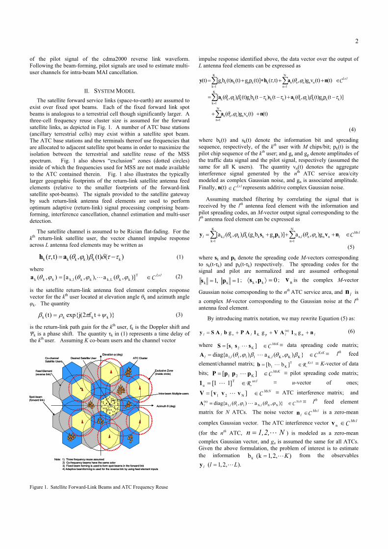
As shown in Fig. 2, the interference canceller for the kth user is a
spatial combiner by using kw as in (13) followed by the
correlator ks . The interference cancelled bit estimate can be
obtained by
)s(
kk xSgnb (14)
where
k
H
k
)s(
k Rex rs (15)
3.3 Channel Estimation
Given that we already have accomplished ATC interference
cancellation and single-user detection, as well as timing and formed-
beam/channel estimates, we are able to reconstruct the MAI and
subtract it from the signal. To reconstruct the MAI, we first need to
estimate the channel for each user by using the pilot signals. We
apply the beam-formed signal kr to a bank of K filters matched to
the users’ delayed pilot signals K21 ppp .
Kx1Ck
H
nN
)n(
k
)pv(
sk
)ps(
pkk
)p(
k
H)p(
k~g
~g
~g
~~ nP1ARbAR1ARrPz
(16)
4
Letting the K-vectorKx1
CT
Kk,k,2k,1k ]ˆˆˆ[ˆ
denote the relevant channel estimates associated with the kth user,
kˆ can be obtained by normalizing
)p(
k~z by the pilot amplitude gp.
The channel estimates may be further improved by integrating over a
period of Q pilot symbols so that the ATC interference residue and
MAI (as well as the noise) are low-pass filtered.
3.4 Sequential ATC and MAI Interference Cancellation (SAMIC)
Detector
We can reconstruct the MAI due to all interferers
( , )j K j k1 by using corresponding formed beam/channel
estimates )kj,ˆ( jk, and bit estimates )kj,b( j
, and subtract the
reconstructed MAI from the beam-formed signal kr .
The sequential ATC and MAI Interference Cancellation (SAMIC)
detector is based on the idea that cancellation of MAI may be
accomplished efficiently following ATC interference cancellation.
The SAMIC detector uses modified signals that are obtained by
subtracting the estimated and reconstructed MAI from the beam-
formed signals:
K1kbgˆ~K
kj,1j
jsjj,kkk
Mx1Csrr (17)
where the channel estimates kˆ are obtained from the pilot channel
after beam-forming, and the bit estimates are obtained in (14) from
single-user detection after beam-forming. Submitting kˆ and
)kj(,b jj s to (17) yields k~r . The MAI-removed k
~r is
followed by the correlator that is matched to the spreading code ks ;
we obtain the maximum-likelihood detector for the kth user as
follows: K
kj,1j
jsj,kj,kknN
)n(
k
H
kpKk
H
ksk
H
kk
H
k bgˆng~
g~
g~~ 1AVs1APsbASsrs
(18)
where
)jk(,j
H
kj,k ss (19)
Figure 2. Interference Canceller and Multi-User Detector
l
l
lnwsnsL
1
H
k
H
kk
H
kk )ˆ(~n (20)
The slicer input for the SAMIC detector is
skknkpkskk
H
k
(s)
k gn~ggg~Rex~ rs (21)
where
bASs k
H
kk
~Re (22)
Kk
H
kk
~Re 1APs (23)
N
)n(
k
H
kk
~Re 1AVs (24)
K
kj,1j
jj,kj,kk bˆRe (25)
kk nRen~ (26)
The final decision for the interference cancelled symbol/bit is the
output of the slicer:
)s(
kk x~sgnb~
(27)
The noise term apparently has the statistics distribution:
22
kkˆ,0~n~ w .
IV. SIMULATION RESULTS
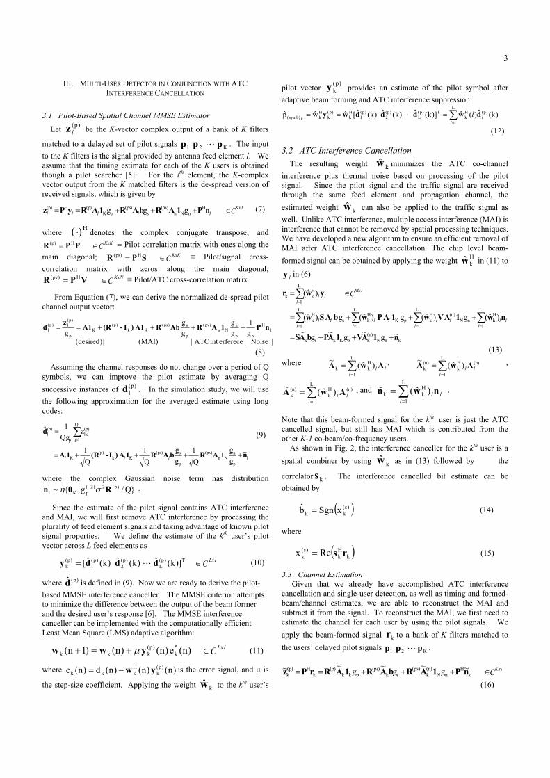
In this section, we present simulation results illustrating the
performance of the ATC interference canceller and the SAMIC
detector. The simulation is based on realistic satellite feed element
gain/phase profiles that have been provided by a major satellite
manufacturer. Fig. 3 illustrates the locations of the ATC (dots) over
CONUS and the contours (footprints) of the return-link antenna feed
elements. Fig. 4 presents performance of ATC-induced interference
suppression as a function of “Satellite Signal to ATC Power ratio that
is launched toward satellite” (SIR). The ATC Power that is launched
toward the satellite is the aggregate co-channel power that is
generated by all surviving ATCs after exclusion zone elimination
(there are 16 such ATCs). In Fig. 4, each surviving ATC is treated
as a point source interferer and all surviving ATCs are assumed to
generate equal co-channel power. The desired satellite signal
(terminal) is assumed to be at the center of feed element #21 (see Fig.
3). The parameter in Fig. 4 is the number of antenna feed elements
(“receivers”) that are processed. It is seen that performance gains
diminish beyond 17 feed elements since, in this scenario, there are
only 16 ATC locations providing interference.
The return link adaptive beam-forming generates an optimal beam
to “null-out” as many sources of interference (ATCs) as possible.
The adaptively generated weights form a beam that creates a null for
each ATC interferer as long as there are sufficient degrees of
freedom. Fig. 5 shows the adaptively formed beam pattern gain
contours with the ATC distribution. In the contour plots, each
contour ring represents 10 dB of gain reduction from the very next
inner contour. The effect of interference cancellation is clearly
demonstrated by the adaptive beam-forming.
5
51
31 11
15
52
12
7
53
33
13
6
54
34
14
24
55
45
35
25
56
46
36
26
32
57
47
37
27
1858
48
28
8
17
49
29
9
165030
10
1
2
3
4
5
19
20
21
22
23
38
39
40
41
42
43
44
59
60
61
62
63
64
65
66
67
68
69
70
71
72
73
74
75
76
77
78
79
80
81
83
82
84
85
86
87
88
S/C at 101 degr. W.L.x-scale = 1 degr. Az per inch.y-scale = 1 degr. El. per inch.Origin offset = 0.8 degr. E., 6.0 degr. N.
Figure 3. Footprint of Antenna Feed Elements and ATC Distribution
over CONUS
Figure 4. Impact of Number of Feed Elements on BER Performance
Figure 5. Contour of Adaptively Formed Beam Pattern and MT/ATC
Locations (with 17 feed elements)
Figure 6. Impact on Canceller Performance of ATC Spread
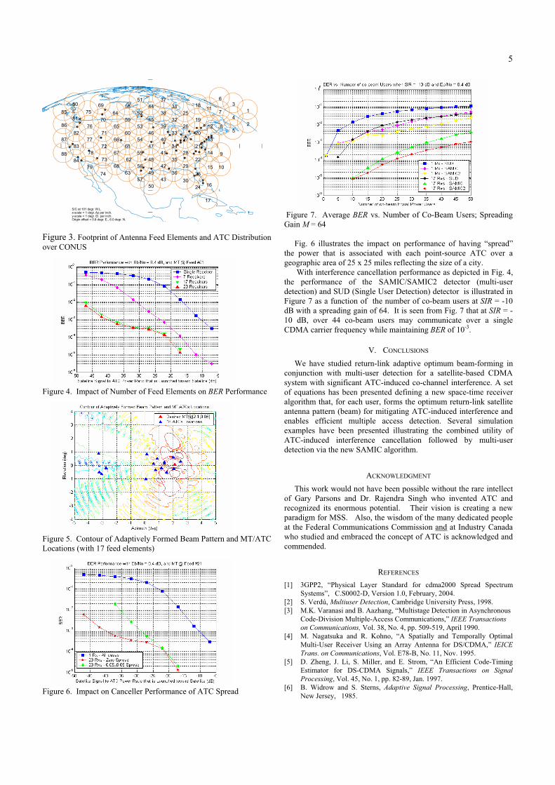
Figure 7. Average BER vs. Number of Co-Beam Users; Spreading
Gain M = 64
Fig. 6 illustrates the impact on performance of having “spread”
the power that is associated with each point-source ATC over a
geographic area of 25 x 25 miles reflecting the size of a city.
With interference cancellation performance as depicted in Fig. 4,
the performance of the SAMIC/SAMIC2 detector (multi-user
detection) and SUD (Single User Detection) detector is illustrated in
Figure 7 as a function of the number of co-beam users at SIR = -10
dB with a spreading gain of 64. It is seen from Fig. 7 that at SIR = -
10 dB, over 44 co-beam users may communicate over a single
CDMA carrier frequency while maintaining BER of 10-3.
V. CONCLUSIONS
We have studied return-link adaptive optimum beam-forming in
conjunction with multi-user detection for a satellite-based CDMA
system with significant ATC-induced co-channel interference. A set
of equations has been presented defining a new space-time receiver
algorithm that, for each user, forms the optimum return-link satellite
antenna pattern (beam) for mitigating ATC-induced interference and
enables efficient multiple access detection. Several simulation
examples have been presented illustrating the combined utility of
ATC-induced interference cancellation followed by multi-user
detection via the new SAMIC algorithm.
ACKNOWLEDGMENT
This work would not have been possible without the rare intellect
of Gary Parsons and Dr. Rajendra Singh who invented ATC and
recognized its enormous potential. Their vision is creating a new
paradigm for MSS. Also, the wisdom of the many dedicated people
at the Federal Communications Commission and at Industry Canada
who studied and embraced the concept of ATC is acknowledged and
commended.
REFERENCES
[1] 3GPP2, “Physical Layer Standard for cdma2000 Spread Spectrum
Systems”, C.S0002-D, Version 1.0, February, 2004.
[2] S. Verdú, Multiuser Detection, Cambridge University Press, 1998.
[3] M.K. Varanasi and B. Aazhang, “Multistage Detection in Asynchronous
Code-Division Multiple-Access Communications,” IEEE Transactions
on Communications, Vol. 38, No. 4, pp. 509-519, April 1990.
[4] M. Nagatsuka and R. Kohno, “A Spatially and Temporally Optimal
Multi-User Receiver Using an Array Antenna for DS/CDMA,” IEICE
Trans. on Communications, Vol. E78-B, No. 11, Nov. 1995.
[5] D. Zheng, J. Li, S. Miller, and E. Strom, “An Efficient Code-Timing
Estimator for DS-CDMA Signals,” IEEE Transactions on Signal
Processing, Vol. 45, No. 1, pp. 82-89, Jan. 1997.
[6] B. Widrow and S. Sterns, Adaptive Signal Processing, Prentice-Hall,
New Jersey, 1985.