3d modeling of cultural heritage objects …maajournal.com/issues/2012/vol12-1/full11.pdf · for...
TRANSCRIPT
ABSTRACT3D modeling of cultural heritage objects is an expanding application area. The selection
of the right technology is very important and strictly related to the project requirements,budget and user’s experience. The triangulation based active sensors, e.g. structured lightsystems are used for many kinds of 3D object reconstruction tasks and in particular for3D recording of cultural heritage objects. This study presents the experiences in the resultsof two such projects in which a close-range structured light system is used for the 3D dig-itization. The paper includes the essential steps of the 3D object modeling pipeline, i.e.digitization, registration, surface triangulation, editing, texture mapping and visualization.The capabilities of the used hardware and software are addressed. Particular emphasis isgiven to a coded structured light system as an option for data acquisition.
3D MODELING OF CULTURAL HERITAGE OBJECTSWITH A STRUCTURED LIGHT SYSTEM
Devrim Akca
Department of Information Technologies, Isik University, TR-34980, Sile, Istanbul, TurkeyFormerly, at the Institute of Geodesy and Photogrammetry, ETH Zurich, CH-8093 Zurich,
Switzerland.
Corresponding author:[email protected]: 16/05/2011Accepted: 10/10/2011
KEYWORDS: active sensors, 3D point cloud, scanning, registration, surface triangulation,visualization
Mediterranean Arhaeology and Archaeometry, Vol. 12, No 1, pp.139-152Copyright © 2012 MAA
Printed in Greece. All rights reserved.

1. INTRODUCTION
Active sensors, based on coherent (laser) and
non-coherent light, are used for many kinds of
3D reconstruction tasks and recently very much
for 3D recording and documentation of cultural
heritage objects. They have become a very com-
mon source of documentation data in recent
years, in particular for non-expert users, as they
provide range data of surfaces automatically in
high resolution and accuracy. Compared to pas-
sive image-based approaches (Remondino and
El-Hakim, 2006), active sensors provide directly
and quickly 3D information of the surveyed ob-
ject in form of range data (point clouds). Active
sensors are suitable for different scales and ob-
jects. While the recording devices are still rela-
tively expensive, important progress has been
made in recent years towards an efficient pro-
cessing and analysis of range data.
Structured light systems consist of one (or
more) camera(s) and an active light source,
which illuminates the object with a known pat-
tern of light sequence. Based on the triangula-
tion principle, the 3D object coordinates can be
recovered in 1-2 seconds with a potential accu-
racy of 50 microns or even better.
This paper reports about two projects where
a coded structured light system (optoTOP-HE™
and optoTOP-SE™, Breuckmann GmbH) is used
for the precise 3D digitization of cultural her-
itage objects. It includes all essential steps of the
3D object modeling pipeline from data acquisi-
tion to 3D visualization. The first study is the 3D
modeling of a part of a marble Herakles statue,
named “Weary Herakles” (Figure 1a), which is
on display in the Antalya Museum (Turkey), dig-
itized with an optoTOP-HE system. The second
study is about the 3D modeling of a Khmer head
sculpture (Figure 1b), which is in the collection
of Museum Rietberg Zurich (Switzerland), digi-
tized using an optoTOP-SE sensor.
The 3D modeling pipeline of the Weary Her-
akles (Akca et al., 2006a; 2006b) and the Khmer
head (Akca et al., 2007) projects have already
been published elsewhere. This paper presents
the both projects in a complete form, explains the
processing steps from the technology perspec-
tive, moreover, gives a comparative evaluation
of the used hardware and software tools.
The next chapter introduces the scanner with
the emphasis on working principle and techni-
cal specifications. The following third and fourth
chapters explain the data acquisition and mod-
eling workflow of the Weary Herakles and the
Khmer head projects, respectively. The fifth
chapter addresses the capabilities and the limi-
tations of the used hardware and software. A
comparison of the used reverse engineering soft-
ware (Geomagic Studio™ and Poly-Works™) is
also reported.
140 DEVRIM AKCA
Figure 1. (a) The Weary Herakles statue in the AntalyaMuseum. (b) The Khmer head sculpture in Museum
Rietberg Zurich.

2. DATA ACQUISITION SYSTEM
2.1. Coded Structured Light System
The key feature of a structured light system is
the replacement of one of the cameras with an
active light source, which illuminates the object
with a known pattern. This solves the corre-
spondence problem in a direct way. Many vari-
ants of the active light principle exist (Beraldin,
2004; Blais, 2004).
The coded structured light technique is based
on a unique codification of each light token pro-
jected onto object. When a token is detected in
the image, the correspondence is directly solved
by the de-codification. It requires a complex light
projection system. There exist many codification
methods (Salvi et al., 2004; Dipanda and Woo,
2005). The time-multiplexing, also called tempo-
ral codification, with a combined Gray code and
phase shifting is the mostly employed technique.
The op-toTOP-HE and optoTOP-SE sensors use
the same technique.
A Gray code is a binary numeral system
where two successive values differ in only one
digit, i.e. 000, 001, 010, 011, … in natural (plain)
binary codes, and 000, 001, 011, 010, … in Gray
binary codes. It was invented and patented by
Frank Gray (Gray, 1953) in Bell Labs. For the case
of coded structured light systems it is superior
to the natural binary codification, since it re-
solves the ambiguity better at the edges of con-
secutive patterns (Figure 2a and 2b).
A sequence of Gray coded binary fringe pat-
terns is projected onto the object (Figure 2c). This
divides the object into a number of 2n sections,
where n is the number of pattern sequences, e.g.
128 sections for n=7. Thus each pixel is associated
with a codeword, which is the sequence of 0s
and 1s obtained from the n patterns. The code-
word establishes the correspondences relating
the image pixels to the pro-jector stripe numbers.
The object space point coordinates are calculated
using the spatial intersection provided that sys-
tem calibration is known. All pixels belonging to
the same stripe in the highest frequency pattern
share the same codeword. This limits the resolu-
tion to half the size of the finest pattern.
An additional periodical pattern is projected
several times by shifting it in one direction in
order to increase the resolution of the system.
For each camera pixel the corresponding projec-
tor stripe number with sub-stripe accuracy is
yielded by a phase shift method (Gühring, 2001;
Pribanic et al., 2010).
2.2. Breuckmann optoTOP-HE and optoTOP-SE
The optoTOP-HE (High End) system (Figure
3), as a high definition topometrical 3D-scanner,
allows the 3-dimensional digitization of objects
with high resolution and accuracy. The op-
toTOP-HE system uses special projection pat-
3D MODELING OF CULTURAL HERITAGE OBJECTS WITH A STRUCTURED LIGHT SYSTEM 141
(c)
(b)(a)
Figure 2. (a) Natural (plain) binary code. (b) Gray bi-nary code. (c) Setup of a fringe projection system
(courtesy of B. Breuckmann).

terns with a combined Gray code and phase shift
technique, which guarantees an unambiguous
determination of the recorded 3D data with
highest accuracy (Breuckmann, 2003). The time
for a single scan takes about 1 second for a 1.4
mega pixel camera. The sensor of the optoTOP-
HE system can be scaled for a wide range of
Field of Views (FOV), by changing the baseline
distance and/or lenses, typically between a few
centimeters up to several meters. Thus, the spec-
ifications of the sensor can be adapted to the spe-
cial demands of a given measuring task.
The optoTOP-SE (Special Edition) series are
the identical systems. The major difference is
that the optoTOP–SE sensors have only three dif-
ferent FOV cases with a fixed 300 mm base
length. More details of the both systems are
given in Table 1.
Table 1. Technical specifications of the used
optoTOP-HE and optoTOP-SE sensors.
optoTOP-HE optoTOP-SE
Field of View (mm) 480 x 360 400 x 315
Depth of View (mm) 320 260
Acquisition time (sec) <1 <1
Weight (kg) 2-3 2-3
Digitization 1280 x 1024 1280 x 1024
(points) (1)
Base length (mm) 600 300
Triangulation
angle (deg) 30 30
Projector pattern 128 order 128 order
sinus sinus
Lamp 100W 100W
halogen halogen
Lateral resolution (μm) ~350 ~300
Feature accuracy
(relative)(2) 1/15000 1/10000
Feature accuracy (μm) ~45 ~50
(1) Current optoTOP-HE version has a dimension of 1384 x1036 points.
(2) According to image diagonal.
3. WEARY HERAKLES PROJECT
The Weary Herakles is a marble statue of the
Greek demigod Herakles, which dates back to
the 2nd century AD (Figure 1a and Figure 4a). It
is a copy of an original bronze statue of Herak-
les sculptured about 330-320 BC by the Greek
master Lysippos of Sikyon. Many artisans de-
voted their skills to replicating this original
around that period. This particular example was
probably carved in the Hadrianic or Antonine
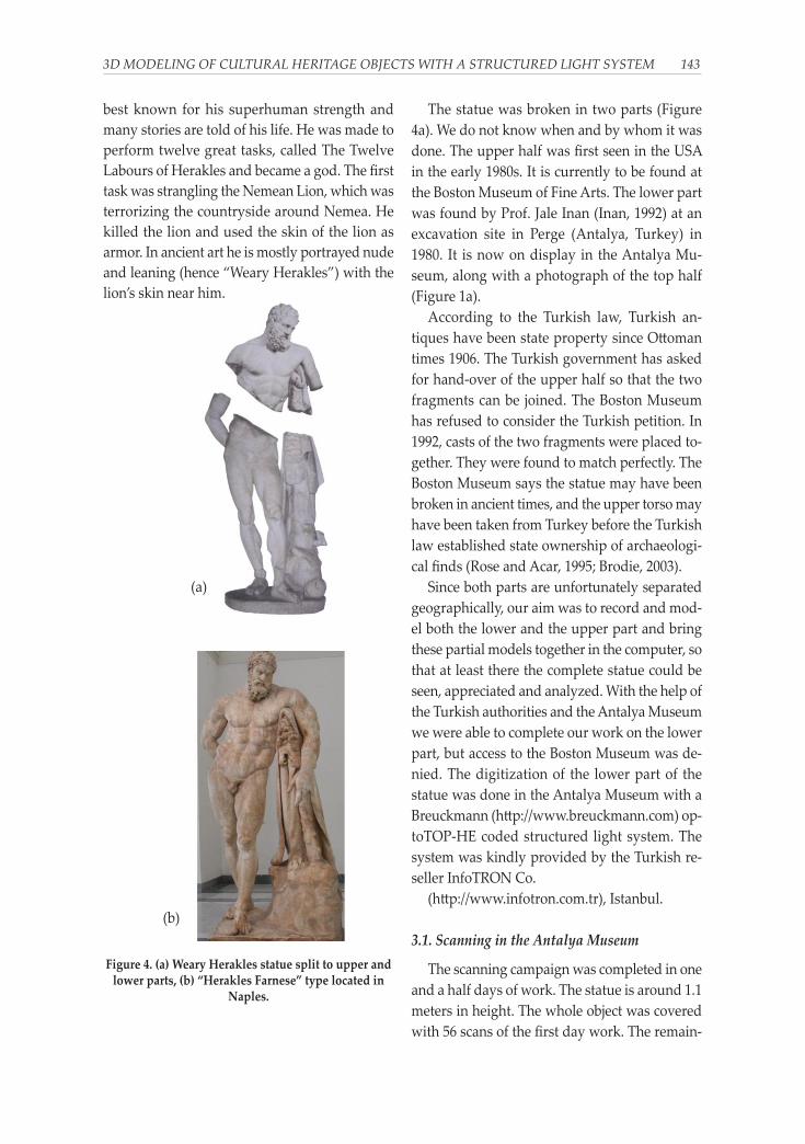
(Roman) period. The version is identified as the
“Herakles Farnese” type on the basis of its simi-
larity to a more complete copy (Figure 4b) in the
Naples National Archaeological Mu-seum
(Italy).
In Greek mythology Herakles (or Heracles)
was the demigod son of Zeus (Jupiter or Jove,
the Roman name) and the mortal Alcmene. In
Roman mythology he was called Hercules. He
was one of the greatest of the mythical heroes,
142 DEVRIM AKCA
(a)
Figure 3. (a) The optoTOP-HE sensor. (b-d) The first 4 fringe projections of a scan of the
optoTOP-HE sensor.
best known for his superhuman strength and
many stories are told of his life. He was made to
perform twelve great tasks, called The Twelve
Labours of Herakles and became a god. The first
task was strangling the Nemean Lion, which was
terrorizing the countryside around Nemea. He
killed the lion and used the skin of the lion as
armor. In ancient art he is mostly portrayed nude
and leaning (hence “Weary Herakles”) with the
lion’s skin near him.
The statue was broken in two parts (Figure
4a). We do not know when and by whom it was
done. The upper half was first seen in the USA
in the early 1980s. It is currently to be found at
the Boston Museum of Fine Arts. The lower part
was found by Prof. Jale Inan (Inan, 1992) at an
excavation site in Perge (Antalya, Turkey) in
1980. It is now on display in the Antalya Mu-
seum, along with a photograph of the top half
(Figure 1a).
According to the Turkish law, Turkish an-
tiques have been state property since Ottoman
times 1906. The Turkish government has asked
for hand-over of the upper half so that the two
fragments can be joined. The Boston Museum
has refused to consider the Turkish petition. In
1992, casts of the two fragments were placed to-
gether. They were found to match perfectly. The
Boston Museum says the statue may have been
broken in ancient times, and the upper torso may
have been taken from Turkey before the Turkish
law established state ownership of archaeologi-
cal finds (Rose and Acar, 1995; Brodie, 2003).
Since both parts are unfortunately separated
geographically, our aim was to record and mod-
el both the lower and the upper part and bring
these partial models together in the computer, so
that at least there the complete statue could be
seen, appreciated and analyzed. With the help of
the Turkish authorities and the Antalya Museum
we were able to complete our work on the lower
part, but access to the Boston Museum was de-
nied. The digitization of the lower part of the
statue was done in the Antalya Museum with a
Breuckmann (http://www.breuckmann.com) op-
toTOP-HE coded structured light system. The
system was kindly provided by the Turkish re-
seller InfoTRON Co.
(http://www.infotron.com.tr), Istanbul.
3.1. Scanning in the Antalya Museum
The scanning campaign was completed in one
and a half days of work. The statue is around 1.1
meters in height. The whole object was covered
with 56 scans of the first day work. The remain-
3D MODELING OF CULTURAL HERITAGE OBJECTS WITH A STRUCTURED LIGHT SYSTEM 143
(a)
(b)
Figure 4. (a) Weary Herakles statue split to upper andlower parts, (b) “Herakles Farnese” type located in
Naples.

ing 11 scans of the second day were for filling the
data holes and occlusion areas. Totally 83.75 mil-
lion points were acquired in 67 scan files. The av-
erage point spacing is 0.5 millimeter.
The optoTOP-HE is an instantaneous 3D dig-
itization system, which enables the acquisition
of one point cloud in nearly less than one second.
However, orienting the scanner and planning the
scan overlay needs careful preparation (Figure
5), especially for this kind of object with many
concave and hidden parts. Due to the sensitivity
of the sensor to ambient light, special attention
was paid to environment lighting conditions.
Two ceiling halogen lamps looking at the statue
were turned off.
3.2. Point Cloud Registration
The pairwise registration was done by use of
an in-house developed method, called Least
Squares 3D Surface Matching (LS3D) (Gruen and
Akca, 2005; Akca, 2010). The mathematical
model is a generalization of the Least Squares
image matching method, in particular the
method given by Gruen (Gruen, 1985). It pro-
vides mechanisms for internal quality control
and the capability of matching of multi-resolu-
tion and multi-quality data sets.
The pairwise LS3D matchings were run on
every overlapping pairs (totally 234) and the
matched point correspondences were saved to
separate files. The average of the sigma naught
(standard deviation of 3D discrepancy) values
was 81 microns. In the successive global regis-
tration step, all these files were passed to a block
adjustment by independent models procedure,
which is a well-known orientation procedure in
photogrammetry. It concluded with 47 micron a
posteriori sigma naught value.
3.3. Point Cloud Editing
After the registration, all scan files were
merged as one XYZ file, discarding the scanner
detected blunders. This file totally contains 36.2
million points. The file was imported to Geo-
magic Studio™ version 6 (Raindrop Geomagic
Inc., USA). All the editing procedures were car-
ried out in Geomagic Studio. The data set was
further cropped to include only the area of in-
terest (AOI), i.e. deleting the background wall or
other non relevant parts, concluding with 33.9
million points. A low level noise reduction was
applied.
3.4. Surface Triangulation and Editing
As a first attempt, the surface mesh genera-
tion was performed at the original data resolu-
tion. The operation could not be succeeded, since
the memory request of the software exceeded the
physical memory limit of 2 GB of the computer.
Therefore, the number of points was reduced to
9.0 million by applying a subsampling proce-
dure based on curvature information. This oper-
ation eliminates points in flat regions but
preserves points in high-curvature regions to
maintain detail.
144 DEVRIM AKCA
Figure 5. Preparation for a scan in the Antalya Museum
(a)

Surface triangulation concluded with 5 mil-
lion triangles. Because of the complexity of the
statue and occlusions, some inner concave parts
could not be seen by the scanner. This resulted
in several data holes on the triangulated surface.
They were interactively filled by use of the cor-
responding functions of Geomagic Studio. In the
final 3D model, we were able to achieve a high
level of realism (Figure 6). The main portion of
the editing effort was dedicated to the hole fill-
ing. It is a tedious work which takes the longest
time among all steps of the project.
3.5. Texture Mapping and Visualization
Separately taken images, with a 4 mega pixel
CCD Leica Digilux 1 camera, were used for the
texture mapping. The Weaver module of the
VCLab’s 3D Scanning Tool (ISTI-CNR, Pisa, Italy)
was used here. The VCLab’s Tool is a bundle of
modules, which comprise the fundamental steps
of the 3D modeling. The algorithmic details of the
software can be found in Callieri et al (2003).
The visualization of the final model was done
with the IMView module of PolyWorks™ ver-
sion 9 (InnovMetric Software Inc., Canada). It
gives a better shading than Geomagic Studio.
The textured 3D model was visualized with the
viewer of the VCLab’s Tool (Figure 7).
4. KHMER HEAD PROJECT
The earliest examples of Buddhist art on the
mainland of Southeast Asia date from the 4th
and 5th centuries and emerged under the influ-
ence of Indian and Sri Lankan art. During the 6th
century the Khmer people established them-
selves in the fertile tropical plains of Cambodia,
and as the dominating power in South-east Asia
in the 12th and 13th centuries. They built the
stunning group of temples at Angkor. The
Khmer rulers supported both Hinduism, dis-
played most magnificently at Angkor Wat, and
Buddhism whose most important monument is
the Bayon temple at Angkor Thom.
A bodhisattva head from the late 12th or ear-
ly 13th century carved in the Bayon style was
scanned in Museum Rietberg Zurich (Figure 1b).
3D MODELING OF CULTURAL HERITAGE OBJECTS WITH A STRUCTURED LIGHT SYSTEM 145
(b)
Figure 6. (a) Picture of the Herakles statue and (b) itsback-projected 3D model.
(a) (b)
Figure 7. Frontal view of the texture mapped 3D mod-el (a), frontal view (b) and back view (c) of the grey
shaded 3D model.
(c)

It is Lokeshvara or Avalokiteshvara, the “Lord of
compassion who looks down (on the suffering of
the world)”, an emanation of the Buddha
Amitabha as demonstrated by the seated Bud-
dha on his hair ornament. His serene expression
and transcendent smile convey better than any
words the sublime essence of the Buddhist teach-
ings (Museum Rietberg, 2006).
4.1. Data Acquisition in Museum Rietberg Zurich
The head is made of sandstone and 28 cen-
timeters in height. The data acquisition was done
in Museum Rietberg Zurich. A Breuckmann Op-
toTOP-SE fringe projection system was used for
this purpose (Figure 8). The scanning and imag-
ing took four hours on site work. The head was
covered with 18 point clouds, totally 23.6 million
points.
4.2. Point Cloud Registration
The point cloud registration was done again
with the LS3D surface matching method. 52 pair-
wise LS3D matchings for all overlaps gave an av-
erage sigma naught value of 60 microns. The
global registration with the block adjustment by
independent models solution concluded with 28
microns sigma naught value.
4.3. Surface Triangulation and Editing
The surface modeling was done by use of two
commercial packages, namely Geomagic Studio
(version 11) and PolyWorks (version 10). The aim
was to compare the capabilities of both software.
The registered point clouds were imported in the
proper file formats. Accordingly, the registration
steps were skipped in both software. Both soft-
ware packages have different processing
pipelines (Table 2).
Geomagic Studio offers fully automatic data
import functionality provided that data is given
in one of the appropriate point cloud formats.
Totally 18 point clouds were imported, merged
into one, which gave a very dense (denser than
50 microns inter-point distance at some loca-
tions) point cloud. After discarding the no-data
or scanner signed erroneous points and points
belonging to background and other non rele-
vant objects, 3.2 million points remained.
Table 2. Modeling workflows in Geomagic
Studio and PolyWorks.
Geomagic Studio PolyWorks
Importing point clouds Importing point clouds
Point cloud merging Surface triangulation
Defining the AOI Surface merging
Noise reduction Defining the AOI
Down sampling Surface editing
Surface triangulation
Surface editing
The noise reduction ensures that points com-
ing from different views in different quality will
finally have the similar signal-to-noise ratio.
Here a slight (low level) noise reduction was ap-
plied. After this step, the model contains highly
redundant points coming from the multiple
views. A curvature based subsampling proce-
dure was performed, reducing the number of
points to 1.9 million.
The surface triangulation in Geomagic Studio
is fully 3D and automatic, with limited user in-
teraction. Hence, the resulting meshes usually
have topological errors and holes. On the other
hand, it can preserve the high frequency details
of the object geometry successfully by consider-
ing all points in one processing sweep. In gen-
eral, surface triangulation quality is highly
146 DEVRIM AKCA
Figure 8. Scanning in Museum Rietberg Zurich.
related to the point density and homogeneity.
PolyWorks has a significantly different work-
flow. Each step is represented as a module inside
the package. Data import is not automatically
performed. Each point cloud is individually im-
ported, subsequently converted to the surface
form by applying a 2.5D triangulation, similar to
the terrain modeling case. Therefore, the user
should interactively rotate the point cloud to a
position where the viewing angle is close to the
one at the acquisition instant. It substantially re-
duces the topological errors. On the opposite
side, such a stepwise surface generation strategy
does not utilize all the available information
properly. For example, there might be some ob-
ject parts with thin point distributions in indi-
vidual views, whereas the combination of all
views together provides a good solution.
In the next step, separate surfaces were
merged as one manifold using the IMMerge
module. This part is highly automated, and ad-
ditionally offers a noise reduction option. Dur-
ing the process, triangulation is also optimized
especially at the overlapping regions by associ-
ating dense triangles to high curvature areas and
sparse at flat areas.
The IMEdit module offers many surface edit-
ing functions, e.g. cropping the AOI, filling the
data holes, correcting the wrong triangles,
boundary cleaning, etc. However, it is less flex-
ible and user friendly than Geomagic Studio.
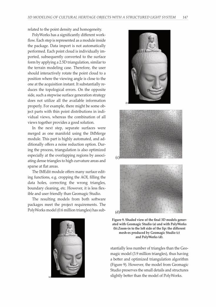
The resulting models from both software
packages meet the project requirements. The
PolyWorks model (0.6 million triangles) has sub-
stantially less number of triangles than the Geo-
magic model (3.9 million triangles), thus having
a better and optimized triangulation algorithm
(Figure 9). However, the model from Geomagic
Studio preserves the small details and structures
slightly better than the model of PolyWorks.
3D MODELING OF CULTURAL HERITAGE OBJECTS WITH A STRUCTURED LIGHT SYSTEM 147
Figure 9. Shaded view of the final 3D models gener-ated with Geomagic Studio (a) and with PolyWorks(b).Zoom-in to the left side of the lip: the different
mesh-es produced by Geomagic Studio (c)and PolyWorks (d).

4.4. Texture Mapping
The digital images of the Khmer head were
acquired with a photographer type of profes-
sional illumination system consisting of two dif-
fuse lights on a tripod (Figure 10). The system
was used to reduce the radiometric differences
between the images and shadow effects at the
complex parts and object silhouettes. Images
were taken with a Sony DSC-W30 6 mega-pixel
digital camera. The 3D model generated with
PolyWorks was used for the texture mapping.
Internal and external orientations of the im-
ages were computed using a photogrammetric
bundle adjustment with self-calibration. The ob-
ject space coordinate system was defined as the
coordinate system of the 3D model. The common
points were interactively identified both in digi-
tal images of the camera and in the intensity im-
ages of the scanner.
An in-house developed texture mapping
method was employed for generating the pho-
torealistic 3D model (Akca et al., 2007; Hanusch,
2008). In this method, the 3D geometric model
and the images (together with their orientation
values) are used to conduct a visibility analysis
for every camera position. The triangles of the
geometric model are back-projected into the im-
ages, and there the intersected and overlaid ones
are searched. Partly occluded triangles are sub-
divided and re-meshed into fully visible or fully
occluded triangles. The resultant list of visible
triangles is used to calculate the texture coordi-
nates of every vertex of the mesh. The underly-
ing algorithm uses a "best viewing angle"
criterion to evaluate the optimal texture for every
triangle.
The final textured model consists of around
295000 vertices and 585000 facets (Figure 11). It
is possible to visualize this model in a standard
rendering software, but the navigation does not
work fluently due to data size, even on comput-
ers with high quality graphic cards, memory and
processing power. To cope with the problem, we
decided to use a special rendering software: the
open source software "Blender". It is an adequate
software package to handle the huge number of
triangles to produce high quality images and
movies.
148 DEVRIM AKCA
Figure 10. The special illumination system used inMuseum Rietberg Zurich
Figure 11. (a) The picture of the Khmer head , and (b)its texture mapped 3D model.

5. CAPABILITIES OF THE USED HARD-
WARE AND SOFTWARE
The optoTOP-HE and optoTOP-SE sensors as
a coded light projection system meet the project
requirements satisfactorily. They have some dis-
tinctive advantages over the triangulation-based
laser systems (Table 3).
The use of incoherent light reduces speckle
noise and provides better surface smoothness
(Blais, 2004). Furthermore, it does not penetrate
into the object surface, unlike laser light whose
penetration property is well known, e.g. for mar-
ble (Godin et al., 2001). All these reasons make
the system a suitable choice for the cultural her-
itage applications. On the other hand, the coded
light systems are very sensitive to ambient light,
requiring almost darkness during the acquisi-
tion. Nevertheless, new developments and ad-
vances in digital projectors allow 3D data
acquisition also under normal light conditions.
Table 3. Triangulation based systems:
Laser light versus coded light
Laser Coded
light
Weight and price Identical Identical
Data acquisition speed Faster
Sensitivity to ambient
light Less
Speckle noise Less
Penetration into object
surface No
Imaging for texture
mapping Yes
Depth of view Larger
Eye safety Better
Geometry-colour
information registration N/A N/A
The last item of Table 3, geometry-colour in-
formation registration, is a property only avail-
able in the modern laser 3D scanning systems.
They use the same laser beam to capture both the
geometry and the colour information, simulta-
neously.
The High Resolution Colour Laser Scanner is
such a system developed by NRC (National Re-
search Council of Canada). It is based on the
auto-synchronized spot scanning principle (Ri-
oux, 1994) and has been developed for digitiz-
ing a range of traditional museum objects
including archaeological and ethnographic col-
lections, paintings, small sculptures and natural
history specimens in colour. The scanner,
mounted on a three-axis translation system,
scans a small (50-100 micron diameter) low
power “white light” laser spot from a RGB laser
source on the object through a synchronized
laser scanning and triangulation detection sys-
tem. The white laser is decomposed to its three
primary components R-G-B. The 3D shape and
colour are recorded simultaneously with high-
resolution and in perfect registration of the XYZ
and RGB components (Baribeau et al., 1992).
In its maximum resolution configuration, this
system provides a spatial (X and Y) resolution of
50 micron and a depth (Z) resolution of 10 mi-
cron. This resolution is sufficient to record and
examine fine brush stroke details on paintings as
well as tool mark features on sculptures and ar-
chaeological objects. On a commercial basis,
NRC has licensed this technology to Arius 3D
(Taylor et al., 2002).
5.1. Geomagic Studio and PolyWorks software
Geomagic is a leading software company pro-
viding solutions in design, reverse engineering
and inspection. The three software products (Ge-
omagic Studio, Geomagic Qualify, and Ge-
omagic Wrap) are mainly used in the aerospace,
turbine machinery, medical devices, dental
CAD/CAM, consumer products, entertainment,
art, archaeology, and automotive industries. The
company was founded in 1997. The headquar-
ters office is located in Research Triangle Park,
North Carolina (USA), with subsidiaries in Eu-
rope and Asia and partners worldwide.
InnovMetric is a software development com-
pany based in Quebec City, Canada, founded in
1994. The company has subsidiaries in USA,
India, China, and a strategic partner (Duwe-3D
3D MODELING OF CULTURAL HERITAGE OBJECTS WITH A STRUCTURED LIGHT SYSTEM 149

AG) in Europe. PolyWorks is the flagship prod-
uct of InnovMetric, and it has been used prima-
rily in archaeology, automotive, aeronautic,
consumer goods, energy and metalworking in-
dustries as a point cloud inspection and reverse
engineering solution. The core algorithms of
PolyWorks have been developed in collaboration
with NRC (Taylor and Beraldin, 2001; Soucy et
al., 1996).
Table 4 gives a comparison of both software
packages. It was prepared to a great extend
based on the experiences gained in the Khmer
head project where Geomagic Studio version 11
and PolyWorks version 10 were employed.
Table 4. PolyWorks versus Geomagic Studio
PolyWorks Geomagic
Data import Manual Automatic
Triangulation
Type 2.5D 3D
Optimality Better
Detail preservation Better
Topological
correctness Better
Automatisation Better
Editing capabilities Better
Performance Better
Visualization Better
User friendliness Better
Stability Better
Although surface digitization is a very easy
and straightforward task, the surface triangula-
tion and editing, which is the key step of the
whole modeling chain, is still cumbersome and
needs heavy semi-automatic or manual work.
The management of large data sets is another as-
pect. Geomagic Studio crushed several times
while filling the holes interactively, whereas
PolyWorks did not. Geomagic Studio gives bet-
ter details in surface geometry with the cost of
large number of triangles.
Another comparison study performed on
larger datasets is presented in Boehm and Pater-
aki (2006).
6. CONCLUSIONS
Active sensors are used for many kinds of 3D
object reconstruction tasks, one important area
of which is 3D documentation of cultural her-
itage objects. This study presents the results of
3D modeling of two cultural heritage objects,
where a close-range coded structured light sys-
tem was used for digitization.
The used instruments have acquired high
quality point cloud data of the objects. The re-
sults of the processing (accuracy of about 50 mi-
cron and better) are in good agreement with the
system specifications and project requirements.
The heaviest user interaction is needed in the ed-
iting steps, e.g. for filling the data holes. We have
used two commercial software packages in order
to carry out the modeling step. Each software
package has its own particular advantages and
functions. A unique package, which fulfills all re-
quirements with sophisticated and automatic ed-
iting capabilities, is not yet available. Usage of
both packages can give the optimal modeling re-
sults. Texture mapping is another issue, which is
not fully supported by either software.
Active sensing with coded structured light
systems is a mature technology and allows high
resolution documentation of cultural heritage
objects.
150 DEVRIM AKCA
ACKNOWLEDGEMENTS
The author thanks the personnel of the Antalya Museum and Museum Rietberg for their kind
help and permission. The author also thanks the Visual Computing Lab of ISTI-CNR for providing
their Weaver software for the texture mapping. Finally, contribution and help of Mr. Thomas Ha-
nusch, Dr. Fabio Remondino, Mr. David Novak, Mr. Nusret Demir, and Prof. Dr. Armin Gruen are
gratefully acknowledged.
REFERENCES
Remondino F., and El-Hakim S. (2006) Image-based modelling: a review. The Photogrammetric Re-
cord, vol. 21, No 115, 269-291.
Akca, D., Gruen, A., Alkis, Z., Demir, N., Breuckmann, B., Erduyan, I., and Nadir, E. (2006a) 3D mod-
eling of the Weary Herakles statue with a coded structured light system. International
Archives of the Photogrammetry, Remote Sensing and Spatial Information Sciences, vol. 36, No
5, 14-19.
Akca, D., Gruen, A., Alkis, Z., Demir, N., Breuckmann, B., Erduyan, I., and Nadir, E. (2006b) 3D mod-
eling of the Weary Herakles statue. In Proceedings of 5th International Symposium Turk-ish-
German Geodetic Days, Berlin, March 28-31, (only on CD-ROM).
Beraldin J.-A. (2004) Integration of laser scanning and close-range photogrammetry – The last dec-
ade and beyond. International Archives of the Photogrammetry, Remote Sensing and Spatial In-
formation Sciences, vol. 35, No B7, 972-983.
Blais F. (2004) Review of 20 years of range sensor development. Journal of Electronic Imaging, vol. 13,
No 1, 231-240.
Salvi J., Pages J., and Batlle J. (2004) Pattern codification strategies in structured light systems. Pat-
tern Recognition, vol. 37, No 4, 827-849.
Dipanda A. and Woo S. (2005) Efficient correspondence problem-solving in 3-D shape reconstruc-
tion using a structured light system. Optical Engineering, vol. 44, No 9, 1-14.
Gray, F. (1953) Pulse code communication. US Patent no. 2,632,058. March 17, 1953.
Gühring, J. (2001) Dense 3-D surface acquisition by structured light using off-the-shelf components.
In Proceedings of the Videometrics VI, San Jose, CA, USA, January 22-23, pp 220-231.
Pribanic T., Mrvoš S. and Salvi J. (2010) Efficient multiple phase shift patterns for dense 3D acquisi-
tion in structured light scanning. Image and Vision Computing, vol. 28, No 8,1255–1266.
Breuckmann B. (2003) State of the art of topometric 3D-metrology. In Proceedings of the Optical 3-D
Measurement Techniques VI, Zurich, Switzerland, September 22-25, Vol. II, pp 152-158.
Inan J. (1992) Heraklesstatue vom Typus des “Herakles Fernese” aus Perge. Festschrift für Max Weg-
ner Zum 90 Geburtstag, Bonn, pp 223-232.
Rose M. and Acar O. (1995) Turkey’s war on the illicit antiquities trade. Archaeology, vol. 48, No 2,
45-56.
Brodie N. (2003) Stolen history: looting and illicit trade. Museum International, vol. 55, No 3-4, 10-22.
Gruen A. and Akca D. (2005) Least squares 3D surface and curve matching. ISPRS Journal of Photo-
grammetry and Remote Sensing, vol. 59, No 3, 151-174.
Akca, D. (2010) Co-registration of surfaces by 3D Least Squares matching. Photogrammetric Engineer-
ing and Remote Sensing, vol. 76, No 3, 307-318.
Gruen A. (1985) Adaptive least squares correlation: a powerful image matching technique. South
African Journal of Photogrammetry, Remote Sensing and Cartography, vol. 14, No 3, 175-187.
Callieri M., Cignoni P., Ganovelli F., Montani C., Pingi P. and Scopigno R. (2003) VCLab’s Tools for
3D range data processing. In Proceedings of the International Symposium on Virtual Reality,
Archaeology and Cultural Heritage (VAST’03), Brighton, UK, November 5-7, pp 13-22. Mu-
seum Rietberg (2006) Exhibition Brochure.
Akca D., Remondino F., Novàk D., Hanusch T., Schrotter G. and Gruen A. (2007) Performance eval-
uation of a coded structured light system for cultural heritage applications. In Proceedings
of the Videometrics IX, San Jose, CA, USA, January 29-30, SPIE vol. 6491, pp 64910V-1-12.
Hanusch T. (2008) A new texture mapping algorithm for photorealistic reconstruction of 3D objects.
3D MODELING OF CULTURAL HERITAGE OBJECTS WITH A STRUCTURED LIGHT SYSTEM 151

In Proceedings of the XXI-th ISPRS Congress, Beijing, China, July 3-11, pp 699-705.
Godin G., Rioux M., Beraldin J.-A., Levoy M. and Cournoyer L. (2001) An assessment of laser range
measurement of marble surfaces. In Proceedings of the Optical 3-D Measurement Techniques
V, Vienna, Austria, October 1-4, pp 49-56.
Rioux, M. (1994) Digital 3-D imaging: theory and applications. In Proceedings of the Videometrics III,
Boston, MA, October 31-November 4, SPIE vol. 2350, pp. 2-15.
Baribeau, R., Rioux M. and Godin G. (1992) Color Reflectance Modelling Using a Polychromatic La-
ser Range Sensor. IEEE Transactions on Pattern Analysis and Machine Intelligence, vol. 14, No
2, 263-269.
Taylor, J., Beraldin, J_A, Godin, G., Cournoyer, L., Rioux, M., and Domey, J. (2002) NRC 3D Imaging
Technology for Museums & Heritage. In Proceedings of The First International Workshop on
3D Virtual Heritage, Geneva, Switzerland, October 2-3, pp. 70-75.
Taylor, J.M., and Beraldin J.-A. (2001) Heritage Recording Applications of High Resolution 3D Im-
aging. In Proceedings of the Electronic Imaging and the Visual Arts (EVA) Conference, Florence,
Italy, March 26-30.
Soucy, M., Godin, G., Baribeau, R., Blais, F. and Rioux, M. (1996) Sensors and Algorithms for the
Construction of Digital 3-D Colour Models of Real Objects. In Proceedings of the IEEE Inter-
national Conference on Image Processing, Lausanne, Switzerland, September 16-19, Vol. II,
pp. 409-412.
Boehm J. and Pateraki M. (2006) From point samples to surfaces - on meshing and alternatives. In
Proceedings of the ISPRS Commission V Symposium, Dresden, Germany, September 25-27,
pp 50-55.
152 DEVRIM AKCA