3d painting on scanned surfaces - uc berkeleyvis.berkeley.edu/papers/3dpaint/3dpaint.pdf · 3d...
TRANSCRIPT
3D Painting on Scanned Surfaces
Maneesh Agrawala Andrew C. Beers
Marc Levoy
Computer Science Department Stanford University
Abstract We present an intuitive interface for painting on unparameterized three-dimensional polygon meshes using a 6D Polhemus space tracker as an input device. Given a physical object we first acquire its surface geometry using a Cyberware scanner. We then treat the sensor of the space tracker as a paintbrush. As we move the sensor over the surface of the physical object we color the corresponding locations on the scanned mesh. The physical object provides a natural force-feedback guide for painting on the mesh, making it intuitive and easy to accurately place color on the mesh.
CR categories: 1.3.6 [Computer Graphics]: Methodology - Inter- action Techniques. 1.3.7 [Computer Graphics]: 3D Graphics and Realism - Color and texture; Visible surface algorithms.
Additional keywords: 3D painting, painting systems, direct ma- nipulation, user-interface.
1 Introduction Painting systems are a very common tool for computer graphics and have been well studied for painting on 2D surfaces. While many two dimensional techniques can be applied to painting on 3D surfaces, there are issues that are unique to 3D object painting. The most important aspect in developing a 3D painting system is maintaining an intuitive, precise and responsive interface. It is crucial that the user be able to place color on the surface mesh easily and accurately.
Many computer graphics studios (including Pixar and Indus- trial Light and Magic) have developed their own 3D paint pro- grams which use a mouse as the input device. These painting systems are often used to paint textures onto the 3D computer graphics models which they will then animate. The user paints on some two-dimensional image representing the three dimensional surface and the program applies an appropriate transformation to convert the 2D screen space mouse movements into movements of a virtual paintbrush over the 3D mesh. Hanrahan and Haeberli describe such a system for painting on three-dimensional param- eterized meshes using a two-dimensional input device in [5]. The main feature of this system, and one which we retain in ours, is
Pertd~iOn to copy without fee all or part of this material is granted provided that the copies are not made or distributed for $reCt commer$al advantage, the ACM copyright notice and the title of the publtcation and Its date appear, and notice is given that copying is by permission of the Association of Computing Machinery. TO copy otherwise, or to republish, requires a fee and/or specific Dermission. 1995 Syinposiu’m on Interactive 3D Graphics, Monterey CA USA 0 1995 ACM O-69791 -736-7/95/0004...$3.50
that painting is done directly on the mesh in a WYSIWYG (What You See Is What You Get) fashion. The drawback of this system is that the transformation from the 2D screen space to the 3D mesh may not always be immediately clear.
This type of system could be extended to use a 3D input device. Movements of a sensor through space would map directly to movements of the virtual paintbrush. Such a system might be difficult to use, however. because there would be no way to “feel” when the paintbrush is touching the mesh surface. This problem could be solved by providing the user with force-feedback, the importance of which is well recognized (see [2], [IO], [4]).
In our system. 3D computer models are built from physical ob- jects, so these objects are available to serve as a guide for painting. As 3D computer graphics applications have become widespread, the demand for 3D models has lead to the development of 3D scanners which can scan the surface geometry of a physical ob- ject. Turk and Levoy have recently developed a technique for taking several scans of an object and “zippering” them together to create a complete surface mesh for the object [I 11. If a sur- face mesh has been derived from a physical object in this way, the quickest, most intuitive method for specifying where to paint the mesh would be to point to the corresponding location on the surface of the physical object.
Our approach is based on this idea. Given a physical object we scan its surface geometry. We then use a 6D Polhcmus space tracker as an input device to the painting system. As we move the sensor of the tracker over the surface of the physical object, we paint the corresponding locations on the surface of the scanned mesh. The sensor of the space tracker can be thought of as a paintbrush, providing a familiar metaphor for understanding how to USC our system.
The remainder of this paper is organized as follows. Section 2 describes the organization of our painting system. Section 3 details how our system represents meshes internally. Section 4 discusses the algorithms and methods we use for painting, reg- istration, and combating registration errors. Our results are pre- sented in section 5. Section 6 discusses possible future directions of this work, and section 7 summarizes our conclusions about our system.
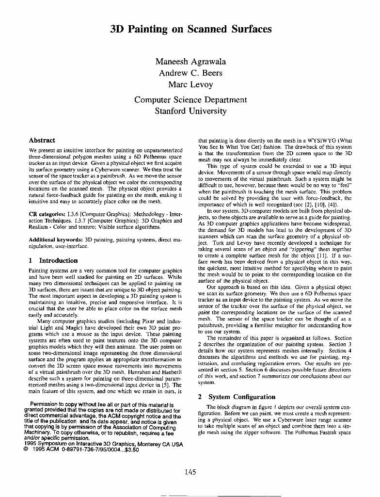
2 System Configuration The block diagram in figure I depicts our overall system con-
liguration. Before we can paint, we must create a mesh represent- ing a physical object. We use a Cyberware laser range scanner to take multiple scans of an object and combine them into a sin- gle mesh using the zipper software. The Polhemus Fastrak space
145
SGI Workstation
scans ----
Display
Figure 1: 3D Painting System Configuration
tracking system tracks the location of a stylus as it is moved over the physical object. The painter application maps these stylus positions to positions on the zippered mesh.
The Cybenvare Scanner uses optical triangulation to determine the distance of points on the object from the scanning system. A sheet of laser light is emitted by the scanner. As the object is passed through this sheet of light, a camera, located at a known position and orientation within the scanner. watches the object. The scanner triangulates the depths of points along the intersection of the object and the laser sheet based on the image captured by the camera. As the object passes through the laser sheet, a mesh of points representing the object as seen from this point of view is formed.
The Polhemus Fastrak tracking system reports the 3D position and orients.tion of a stylus used to select the area on the mesh to paint. A field generator located near the object emits an AC magnetic field which is detected by sensors in the stylus to deter- mine the stylus’s position and orientation with respect to the field generator. The painter application continously polls the tracker for the stylus’ poisiton and orientation at about 30 Hertz.
3 Data Representation Previous work in 3D painting has only allowed painting on param- eterized meshes, or on meshes that have texture coordinates previ- ously assigned at each mesh point. Paint or surface properties ap- plied to these meshes can be stored in a texture map. in the former cast using the parameter values at points on the mesh as texture coordinates. While Maillot, Yahia. and Verroust have developed a method for parameterizing smooth surface representations(91, there are no general techniques for parameterizing arbitrary sur- fact meshes.
Although a single Cyberware scan results in a parameterized triangle mesh, suitable for use by other 3D painting systems, such a mesh is generally not a complete description of the object. This incompleteness is due to self-occlusions on the object, making some points on the object invisible to a rotational scan. By com- bining data from multiple scans, Turk and Levoy’s zippering algo- rithm [ 1 I] produces a more complctc mesh for the object. How- ever, the resulting mesh is irregular and unparameterized. so we lose the ability to store surface characteristics in texture maps.
To paint on unparameterized meshes, we store surface charac- teristics (e.g. color and lighting model coefficients) at each mesh vertex. When painting on the object, these surface characteris- tics are changed only at the mesh vertices. We render the mesh
using the SGI hardware Gouraud shading to interpolate the color between the vertices of triangles composing the mesh. Because we do not require regular or parameterized meshes, our algo- rithm works with meshes acquired from many different kinds of scanning technologies. including hand digitizers, CT scanners and MRI scanners. CT and MRI scanners produce volume data rather than a surface mesh and so an algorithm like marching cubes [8] would be required to convert the volume data set into a suitable mesh representation.
Since we only have color information at the vertices of the mesh polygons. the polygons should be small enough to avoid sampling artifacts when displaying the mesh. As Cook, Carpenter and Catmull point out in their description of the REYES rendering architecture [3], this is possible when polygons are on the order of a half pixe.1 in size. Due to memory constraints we typically paint on meshes in which triangles are about the size of a pixel when the mesh is displayed at a “reasonable” size (e.g. a quarter of the size of the monitor). We have implemented controls for scaling the display of the mesh so that it is always possible to reduce its display size to achieve subpixel color accuracy.
Since we would like to use a mesh with small triangles, the number of triangles in a typical mesh may be quite large. We therefore need to augment the triangle mesh with a spatial data representation that will allow us to find mesh vertices quickly. To facilitate this, WC uniformly voxelize space. Associated with each voxel is a list of vertices on the mesh that arc contained in that voxel. Storing these voxels in a hash table gives us nearly constant-time access to any vertex on the mesh, given a point close to it. Alternatively we could have used a hierarchical repre- sentation such as an octree for storing the spatial representation.
We do not use a simple 3D array indexed by voxel location because most meshes will contain large empty regions in voxel space. By using a hash table, we do not explicitly store the empty regions of voxel space. which results in a tremendous reduction in memory usage.
4 Methods
4.1 Object-mesh registration When painting an object with our system, the user places the
object on a table in front of the workstation. Before we can paint the mesh, we need to determine a transformation bctwcen po- sitions reported by the tracking system in the coordinate space of the physical object and points in the coordinate space of the mesh. We would also like this transformation to ensure that rela- tive orientations of the physical stylus and the virtual paintbrush are the same. We can accomplish this by finding an affme, shear- free transformation between the two coordinate spaces. We use a method developed by Horn [6] for obtaining such a transfo.rma- tion.
Horn’s method determines a translation, rotation. and scaling that will align points in one coordinate system to corresponding points in anol.her coordinate system, while minimizing the total distance between the sets of points. The two sets of points may be collected as follows. First, the mouse is used to select a point on the mesh. Then, the stylus is used to point to the corresponding point on the object. thus specifying a correspondence pair. Horn’s method requires three or more of these correspondence pairs to determine the registration transformation.
There are several sources of error in collecting the two sets of points including inaccuracies in the tracking system, and in- accuracies in matching the points on the mesh to points on the object. Howcvcr. as the number of correspondence pairs is in- creased, small alignment errors in individual pairs arc averaged out and the total alignment error decreases. Ilnfortunately, spcci- fying correspondence pairs is tedious and time consuming.
146
Sensor Sample Points
Mesh
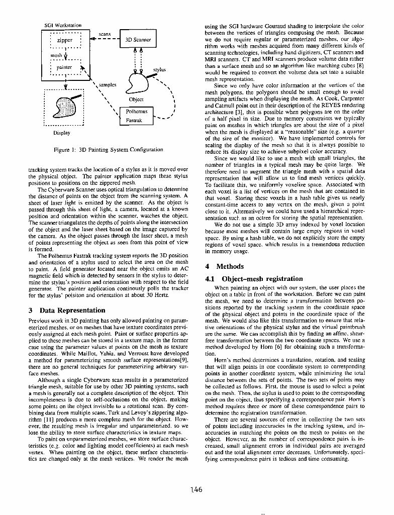
Figure 2: A large set of sensor sample points is collected by running the sensor of the space tracker randomly over the surface of the object. These sensor points are roughly hand-aligned with the mesh, and then Besl’s algorithm is used to obtain a more precise alignment.
An algorithm developed by Besl[l] ovcrcomcs this problem. Although two sets of points are still required, it is not necessary to specify the point-to-point correspondences between them. We collect a large set of points in tracker space by sampling the po- sition of the stylus while randomly moving it across the surface of the physical object. We use a subset of the mesh vertices as the other set of points. Besl’s algorithm determines the best transformation between the two sets of points by iterating on the following steps. First an approximate correspondence between the two sets of points is computed, based on their proximity in space. Then, Horn’s method is applied to these pairs of points to align them more closely. On each successive iteration of the algorithm, the proximity-based correspondence improves, which in turn improves the transformation generated by Horn’s method.
Besl’s algorithm is guaranteed only to find a locally optimal alignment. not a globally optimal one. Therefore, we need to ensure that the sensor samples and the mesh are initially aligned such that the globally optimal solution can be found. The ini- tial alignment is done by hand as (see figure 2). and is often a difficult and time consuming process. To speed this process, we have added the ability to easily generate a rough alignment of the sensor samples to the mesh. Once we have collected the large set of sensor samples. we ask the user to specify three or more correspondence pairs as described at the beginning of this section. From these pairs we calculate the scale factor between the sensor samples and the mesh. We also translate the centroid of the sensor correspondence points so that it is aligned with the centroid of the mesh. This produces a rough alignment of the sensor samples to the mesh which can then be hand-refined to produce the initial alignment required for Besl’s algorithm.
Our registration scheme is summarized as follows:
I. The user collects many samples of the physical object’s surface by running the stylus over the object.
2. The user selects three or more points on the mesh, and points to their corresponding locations on the physical object with the stylus. These correspondence pairs are used to compute a rough alignment of the sensor samples collected during step 1 to the mesh.
3. If necessary, the user makes further hand adjustments to the rough alignment of the sensor samples to the mesh using the mouse to bring them into initial alignment.
4. Besl’s algorithm is run to refine the alignment of the sensor samples to the mesh.
/
Brush
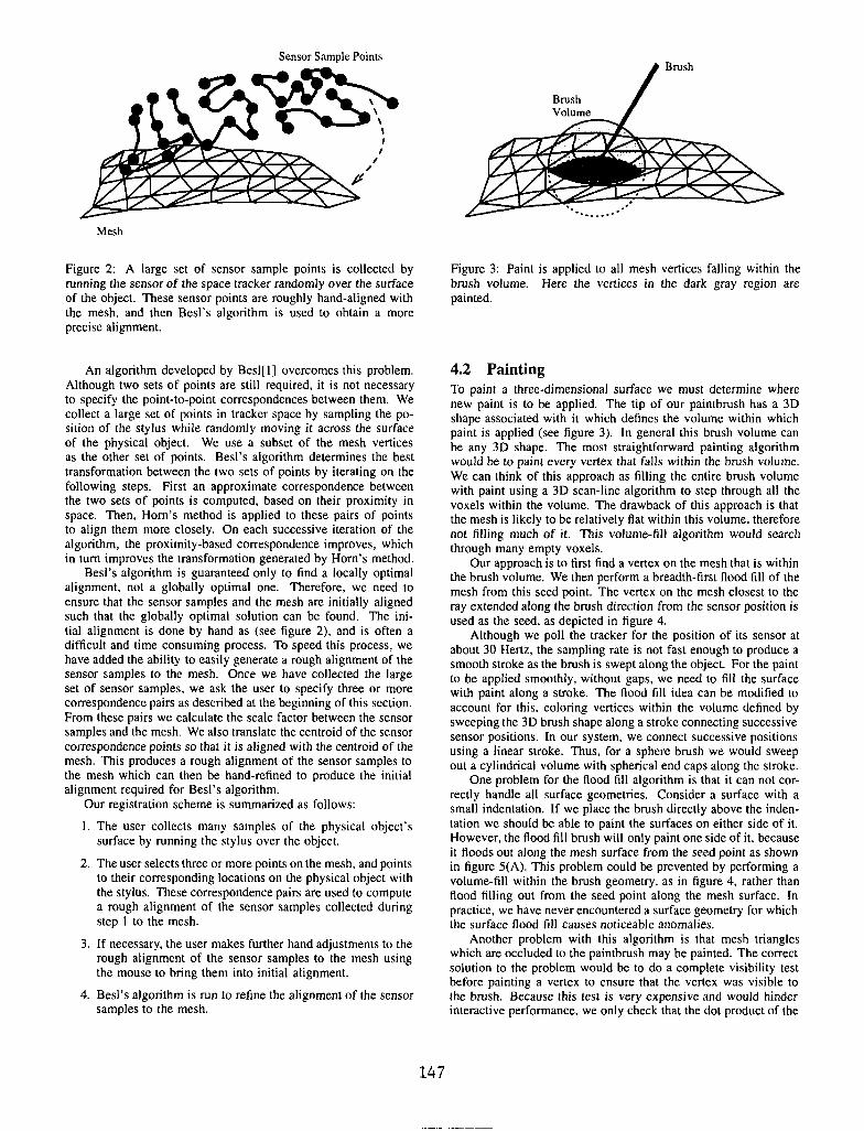
Figure 3: Paint is applied to all mesh vertices falling within the brush volume. Here the vertices in the dark gray region are painted.
4.2 Painting To paint a three-dimensional surface we must determine where new paint is to be applied. The tip of our paintbrush has a 3D shape associated with it which defines the volume within which paint is applied (see figure 3). In general this brush volume can be any 3D shape. The most straightforward painting algorithm would be to paint every vertex that falls within the brush volume. We can think of this approach as filling the entire brush volume with paint using a 3D scan-line algorithm to step through all the voxels within the volume. The drawback of this approach is that the mesh is likely to be relatively flat within this volume, therefore not filling much of it. This volume-fill algorithm would search through many empty voxels.
Our approach is to first find a vertex on the mesh that is within the brush volume. We then perform a breadth-first flood fill of the mesh from this seed point. The vertex on the mesh closest to the ray extended along the brush direction from the sensor position is used as the seed, as depicted in figure 4.
Although we poll the tracker for the position of its sensor at about 30 Hertz, the sampling rate is not fast enough to produce a smooth stroke as the brush is swept along the object. For the paint to be applied smoothly, without gaps, we need to fill the surface with paint along a stroke. The flood fill idea can be modified to account for this. coloring vertices within the volume defined by sweeping the 3D brush shape along a stroke connecting successive sensor positions. In our system, we connect successive positions using a linear stroke. Thus, for a sphere brush we would sweep out a cylindrical volume with spherical end caps along the stroke.
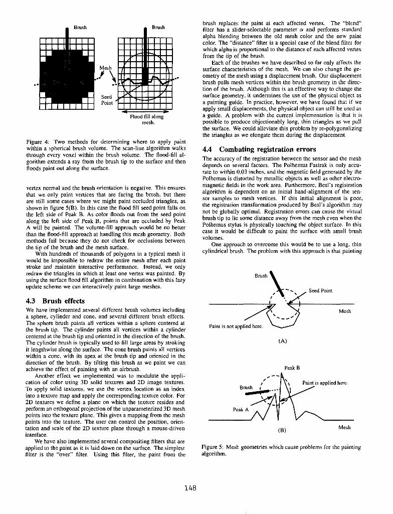
One problem for the flood fill algorithm is that it can not cor- rectly handle all surface geometries. Consider a surface with a small indentation. If we place the brush directly above the inden- tation WC should be able to paint the surfaces on either side of it. However, the flood fill brush will only paint one side of it, because it floods out along the mesh surface from the seed point as shown in figure 5(A). This problem could be prevented by performing a volume-fill within the brush geometry, as in figure 4, rather than flood filling out from the seed point along the mesh surface. In practice, we have never encountered a surface geometry for which the surface flood fill causes noticeable anomalies.
Another problem with this algorithm is that mesh triangles which are occluded to the paintbrush may be painted. The correct solution to the problem would be to do a complete visibility test before painting a vertex to ensure that the vertex was visible to the brush. Because this test is very expensive and would hinder interactive performance, we only check that the dot product of the
147
Brush
Seed Point ’
Brush
D Flood till along
mesh.
Figure 4: Two methods for determining where to apply paint within a spherical brush volume. The scan-line algorithm walks through every voxel within the brush volume. The flood-fill al- gorithm extends a ray from the brush tip to the surface and then floods paint out along the surface.
vertex normal and the brush orientation is negative. This ensures that we only paint vertices that are facing the brush, but there are still some cases where we might paint occluded triangles, as shown in figure 5(B). In this case the flood fill seed point falls on the left side: of Peak B. As color floods out from the seed point along the left side of Peak B, points that are occluded by Peak A will be painted. The volume-fill approach would be no better than the flood-fill approach at handling this mesh geometry. Both methods fail because they do not check for occlusions between the tip of the brush and the mesh surface.
With hundreds of thousands of polygons in a typical mesh it would be impossible to redraw the entire mesh after each paint stroke and maintain interactive performance. Instead, we only redraw the triangles in which at least one vertex was painted. By using the surface flood fill algorithm in combination with this lazy update scheme we can interactively paint large meshes.
4.3 Brush effects We have implemented several different brush volumes including a sphere, cylinder and cone, and several different brush effects. The sphere brush paints all vertices within a sphere centered at the brush tip. The cylinder paints all vertices within a cylinder centered at the brush tip and oriented in the direction of the brush. The cylinder brush is typically used to fill large areas by stroking it lengthwise along the surface. The cone brush paints all vertices within a cone, with its apex at the brush tip and oriented in the direction of the brush. By tilting this brush as we paint we can achieve the Ieffect of painting with an airbrush.
Another effect we implemented was to modulate the appli- cation of color using 3D solid textures and 2D image textures. To apply solid textures, we use the vertex location as an index into a texture map and apply the corresponding texture color. For 2D textures we define a plane on which the texture resides and perform an orthogonal projection of the unparameterized 3D mesh points into the texture plane. This gives a mapping from the mesh points into the texture. The user can control the position, orien- tation and scale of the 2D texture plane through a mouse-driven interface.
We have also implemented several compositing filters that are applied to the paint as it is laid down on the surface. The simplest filter is the “over” filter. Using this filter, the paint from the
brush replaces the paint at each affected vertex. The “blend” filter has a slider-selectable parameter (Y and performs standard alpha blending between the old mesh color and the new paint color. The “distance” filter is a special case of the blend filter for which alpha is proportional to the distance of each affected vertex from the tip OF the brush.
Each of the brushes we have described so far only affects the surface characteristics of the mesh. We can also change the ge- ometry of the mesh using a displacement brush. Our displacement brush pulls mesh vertices within the brush geometry in the direc- tion of the brush. Although this is an effective way to change the surface geometry. it undermines the use of the physical object as a painting guide. In practice, however, we have found that if we apply small displacements, the physical object can still be used as a guide. A problem with the current implementation is that it is possible to produce objectionably long, thin triangles as we pull the surface. We could alleviate this problem by re-polygonalizing the triangles a:s we elongate them during the displacement.
4.4 Combating registration errors The accuracy of the registration between the sensor and the mesh depends on several factors. The Polhemus Fastrak is only accu- rate to within 0.03 inches. and the magnetic field generated by the Polhemus is distorted by metallic objects as well as other electro- magnetic fields in the work area. Furthermore, Besl’s registration algorithm is dependent on an initial hand-alignment of the sen- sor samples to mesh vertices. If this initial alignment is poor, the registration transformation produced by Besl’s algorithm may not be globally optimal. Registration errors can cause the virtual brush tip to lie some distance away from the mesh even when the Polhemus stylus is physically touching the object surface. In this case it would be difficult to paint the surface with small brush volumes.
One approach to overcome this would be to use a long, Ithin cylindrical brush. The problem with this approach is that painting
Paint is not applied here.
6%
P&B
Paint is applied hrrc.
(B)
Figure 5: Mesh geometries which cause problems for the painting algorithm.
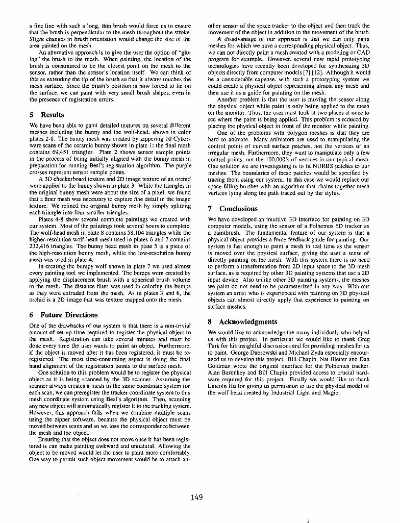
a fine line with such a long, thin brush would force us to ensure that the brush is perpendicular to the mesh throughout the stroke. Slight changes in brush orientation would change the size of the area painted on the mesh.
An alternative approach is to give the user the option of “glu- ing” the brush to the mesh. When painting, the location of the brush is constrained to be the closest point on the mesh to the sensor, rather than the sensor’s location itself. We can think of this as extending the tip of the brush so that it always touches the mesh surface. Since the brush’s position is now forced to lie on the surface, we can paint with very small brush shapes, even in the presence of registration errors.
5 Results We have been able to paint detailed textures on several different meshes including the bunny and the wolf-head, shown in color plates 2-8. The bunny mesh was created by zippering 10 Cyber- ware scans of the ceramic bunny shown in plate 1: the final mesh contains 69.451 triangles. Plate 2 shows sensor sample points in the process of being initially aligned with the bunny mesh in preparation for running Besl’s registration algorithm. The purple crosses represent sensor sample points.
A 3D checkerboard texture and 2D image texture of an orchid were applied to the bunny shown in plate 3. While the triangles in the original bunny mesh were about the size of a pixel, we found that a finer mesh was necessary to capture fine detail in the image texture. We refined the original bunny mesh by simply splitting each triangle into four smaller triangles.
Plates 4-8 show several complete paintings we created with our system. Most of the paintings took several hours to complete. The wolf-head mesh in plate 8 contains 58.104 triangles while the higher-resolution wolf-head mesh used in plates 6 and 7 contains 232,416 triangles. The bunny head mesh in plate 5 is a piece of the high-resolution bunny mesh, while the low-resolution bunny mesh was used in plate 4.
In creating the bumpy wolf shown in plate 7 we used almost every painting tool we implemented. The bumps were created by applying the displacement brush with a spherical brush volume to the mesh. The distance filter was used in coloring the bumps as they were extruded from the mesh. As in plates 3 and 6, the orchid is a 2D image that was texture mapped onto the mesh.
6 Future Directions One of the drawbacks of our system is that there is a non-trivial amount of set-up time required to register the physical object to the mesh. Registration can take several minutes and must be done every time the user wants to paint an object. Furthermore, if the object is moved after it has been registered, it must be re- registered. The most time-consuming aspect is doing the final hand alignment of the registration points to the surface mesh.
One solution to this problem would be to register the physical object as it is being scanned by the 3D scanner. Assuming the scanner always creates a mesh in the same coordinate system for each scan, we can preregister the tracker coordinate system to this mesh coordinate system using Besl’s algorithm. Then, scanning any new object will automatically register it to the tracking system. However, this approach fails when we combine multiple scans using the zipper software, because the physical object must be moved between scans and so we lose the correspondence between the mesh and the object.
Ensuring that the object does not move once it has been regis- tered is can make painting awkward and unnatural. Allowing the object to be moved would let the user to paint more comfortably. One way to permit such object movement would be to attach an-
other sensor of the space tracker to the object and then track the movement of the object in addition to the movement of the brush.
A disadvantage of our approach is that we can only paint meshes for which we have a corresponding physical object. Thus, we can not directly paint a mesh created with a modeling or CAD program for example. However, several new rapid prototyping technologies have recently been developed for synthesizing 3D objects directly from computer models [7] [12]. Although it would be a considerable expense. with such a prototyping system we could create a physical object representing almost any mesh and then use it as a guide for painting on the mesh.
Another problem is that the user is moving the sensor along the physical object while paint is only being applied to the mesh on the monitor. Thus, the user must look at two places at once to see where the paint is being applied. This problem is reduced by placing the physical object in front of the monitor while painting.
One of the problems with polygon meshes is that they are hard to animate. Many animators are used to manipulating the control points of curved surface patches, not the vertices of an irregular mesh. Furthermore, they want to manipulate only a few control points, not the 100,000’s of vertices in our typical mesh. One solution we are investigating is to fit NURBS patches to our meshes. The boundaries of these patches would bc specified by tracing them using our system. In this case we would replace our space-filling brushes with an algorithm that chains together mesh vertices lying along the path traced out by the stylus.
7 Conclusions We have developed an intuitive 3D interface for painting on 3D computer models. using the sensor of a Polhemus 6D tracker as a paintbrush. The fundamental feature of our system is that a physical object provides a force feedback guide for painting. Our system is fast enough to paint a mesh in real time as the sensor is moved over the physical surface. giving the user a sense of directly painting on the mesh. With this system there is no need to perform a transformation from 2D input space to the 3D mesh surface. as is required by other 3D painting systems that use a 2D input device. Also unlike other 3D painting systems, the meshes we paint do not need to be parameterized in any way. With our system an artist who is experienced with painting on 3D physical objects can almost directly apply that experience to painting on surface meshes.
8 Acknowledgments We would like to acknowledge the many individuals who helped us with this project. In particular we would like to thank Greg Turk for his insightful discussions and for providing meshes for us to paint. George Dabrowski and Michael Zyda especially encour- aged us to develop this project. Bill Chapin, Nat Bletter and Dan Goldman wrote the original interface for the Polhemus tracker. Alan Baronkcy and Bill Chapin provided access to crucial hard- ware required for this project. Finally we would like to thank Lincoln Hu for giving us permission to use the physical model of the wolf head created by Industrial Light and Magic.
149
REFERENCES [l] Paul J. Besl. A Method for Registration of 3D Shapes.
IEEE Trans. on Pattern Analysis and Machine Intelligence, 14(2)::239-255. February 1992.
[2] Frederick P. Brooks, Jr., Ming Ouh-Young, James J. Batter, and P. Jerome Kilpatrick. Project GROPE - Haptic Dis- plays for Scientific visualization. In Forest Baskett, editor, Proceedings of SIGGRAPH ‘90, volume 24, pages 177-185, August 1990.
[3] Robert L. Cook, Loren Carpenter, and Edwin Catmull. The Reyes Image Rendering Architecture. In Maureen C. Stone, editor, Proceedings of SIGGRAPH ‘87. pages 95-102, July 1987.
[4] Tinsley A. Galyean and John F. Hughes. Sculpting: An Interactive Volumetric Modeling Technique. In Proceedings of SIGGRAPH ‘91, volume 25, pages 267-274, July 1991.
[5] Pat Hanrahan and Paul Haeberli. Direct WYSIWYG Painting and Texturing on 3D Shapes. In Proceedings of SIGGRAPH ‘90. volume 24, pages 215-223, August 1990.
[6] Berthold K.P. Horn. Closed-form Solution of Absolute Ori- entation Using Unit Quatemions. J. of the Optical Sociery of America, 4(4):629-642. April 1987.
[7] N.F. Kinzie. Three-Dimensional Printing: a Tool for Solid Modeling. In Conference Proceedings of NCGA ‘91. pages 812-8:!1, April 1991.
[8] William E. Lorensen and Harvey E. Cline. Marching Cubes: A High Resolution 3D Surface Construction Algorithm. In Maureen C. Stone, editor, Proceedings of SIGGRAPH ‘87, volume 21, pages 163-169, July 1987.
[9] J&me Maillot, Hussein Yahia, and Anne Verroust. Interac- tive Texture Mapping. In James T. Kajiya, editor, Proceed- ings oj’ SIGGRAPH ‘93, volume 27, pages 27-34, August 1993.
[lo] Margaret Minsky, Ming Ouh-young, Oliver Steele, Freder- ick P. Brooks, Jr., and Max Behensky. Feeling and Seeing: Issues in Force Display. In Rich Riesenfeld and Carlo Se- quin, editors, Computer Graphics (1990 Symposium on In- teractive 3D Graphics), volume 24, pages 235-243. March 1990.
[ 1 l] Greg Turk and Marc Levoy. Zippered Polygon Meshes from Range Images. In Proceedings of SIGGRAPH ‘94. pages 311-318, July 1994.
[ 121 T.T. Wohlers. Developments in 3D Printing and Rapid Pro- totyping. In Conference Proceedings of NCGA ‘91, pages 249-259, April 1991.
150
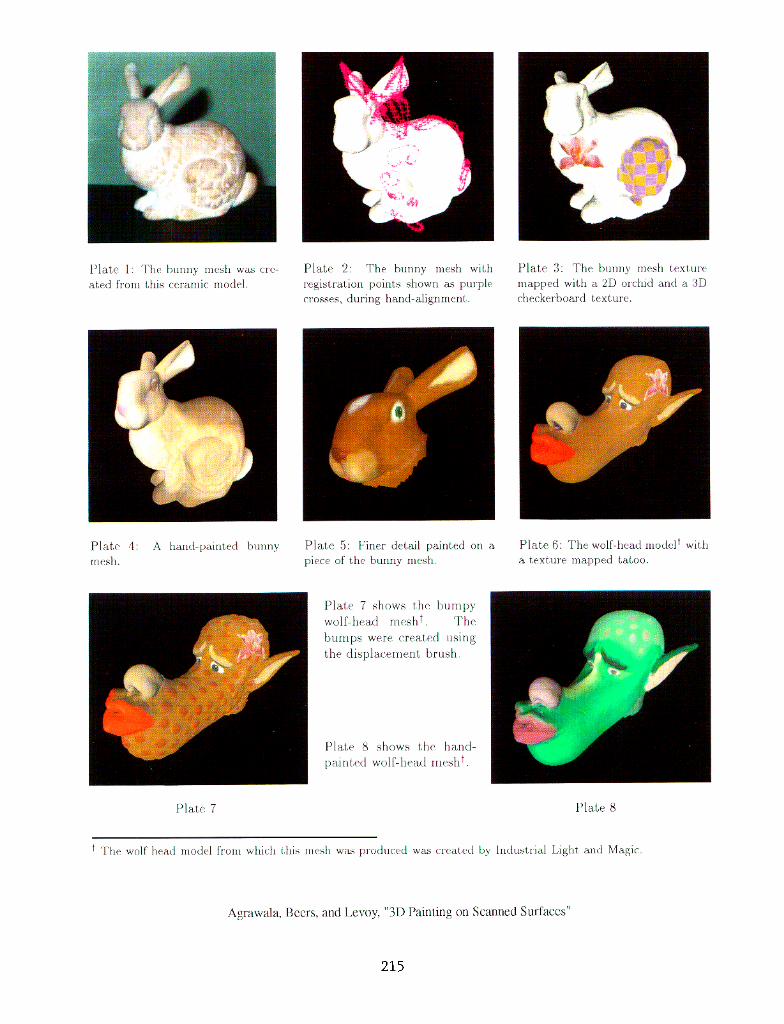
Plate 1: ‘l‘he bunny Iuesh wils cre- ated from this ceranlic model.
Plate 2: The bunny mesh with Plate 3: The ~UIII~~ nlesh t.exture registrat,ion points shown as: purple rnapped with a 2D orchid and a SD crosses, during halId-alignment.. checkerboard t,exture.
Plate 4: A hand-yaintcd bunny mesh.
Plate 5: Finer detail painted on a piece of the bunny nlesh.
Plate 7 shows the bumpy wolf-head mesh+. ‘l’he bumps were created using the displacement brush.
PI& h shows the hand- paint,ed wolf-head m&l+.
Plate 6: The wolf-head modclt witll a texture mapped tatoo.
PIaLe 7 Plate 8
+ The wolf head 1nodr1 frown which this rue& ~a.5 produced ws creat.rd by Indust.rial Light and Magic
Agrawala, Beers. arid 1 ~voy, “31) Painting on Scanned Surfaces”
215