3d tutorials - basic polygon modelling
TRANSCRIPT
8/8/2019 3D Tutorials - Basic Polygon Modelling
http://slidepdf.com/reader/full/3d-tutorials-basic-polygon-modelling 1/14
3D TutorialsBasic Polygon Modelling
Tutor: Robin Sloan [email protected]
This series of tutorials will cover the basics of 3D modelling, texturing and
animation in Autodesk Maya 2008. However, many of the core concepts will beapplicable to other versions of Maya and other 3D packages.
1. Introduction
This tutorial focuses on basic polygon modelling techniques, using a range of simple
tools that can be used to add or subtract vertices, edges, and faces from polygonmeshes. If you are new to Maya, it is recommended that you first read the tutorialsInterface, Navigation and Transformation Tools and Creating and Manipulating
Polygon Primitives.
Before you begin this tutorial, make sure that you have Polygons selected in theMenu Selector on the status line. In older versions of Maya, this menu set is calledModelling. For the duration of this tutorial, you will be accessing tools from theCreate and Edit Mesh (Edit Polygon in older versions of Maya) drop down menus.
2. Split Polygon Tool and Cut Faces Tool
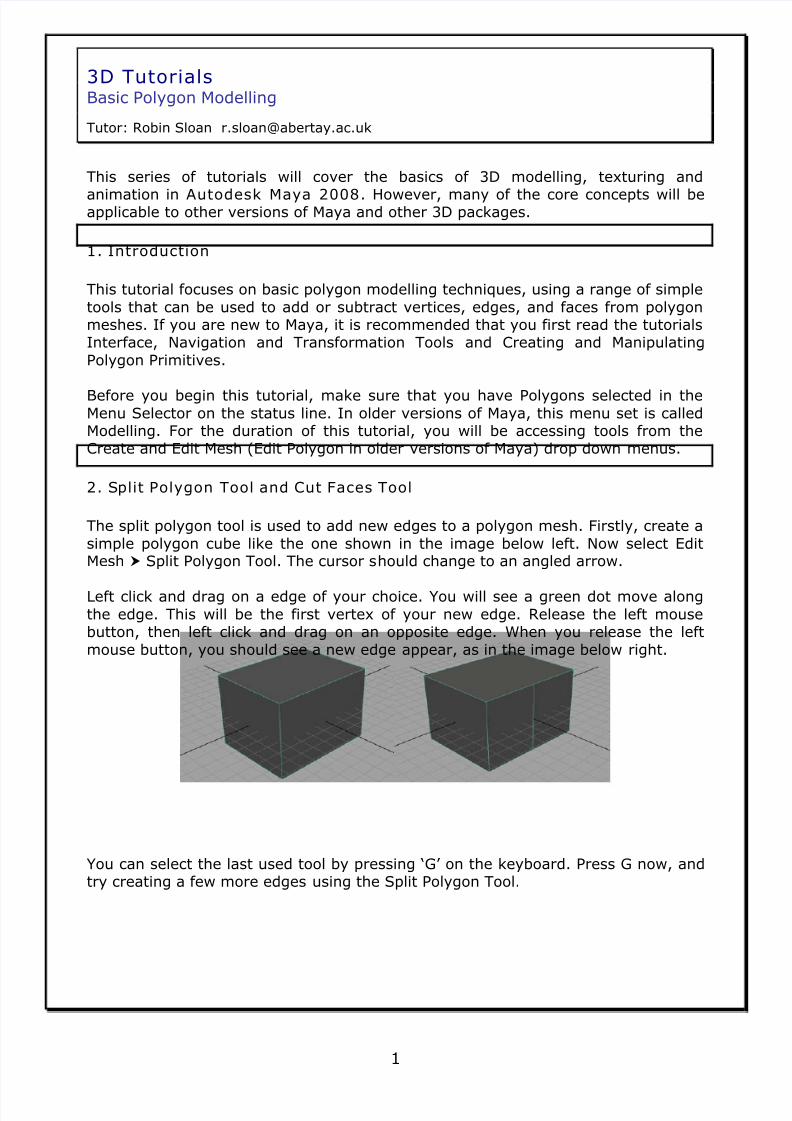
The split polygon tool is used to add new edges to a polygon mesh. Firstly, create a
simple polygon cube like the one shown in the image below left. Now select EditMesh Split Polygon Tool. The cursor should change to an angled arrow.
Left click and drag on a edge of your choice. You will see a green dot move along
the edge. This will be the first vertex of your new edge. Release the left mousebutton, then left click and drag on an opposite edge. When you release the left
mouse button, you should see a new edge appear, as in the image below right.
You can select the last used tool by pressing ‘G’ on the keyboard. Press G now, andtry creating a few more edges using the Split Polygon Tool.
1

8/8/2019 3D Tutorials - Basic Polygon Modelling
http://slidepdf.com/reader/full/3d-tutorials-basic-polygon-modelling 2/14
3D TutorialsBasic Polygon Modelling
Tutor: Robin Sloan [email protected]
You can access the tool options for most tools by clicking on the next to the tool
in the drop down menus. Select Edit Mesh Split Polygon Tool to bring up thewindow shown below.
From the tool options, change divisions to 2. Now, when you create a new edge,you will have a midpoint vertex on the new edge, which can then be selected andmanipulated (as shown below).
2

8/8/2019 3D Tutorials - Basic Polygon Modelling
http://slidepdf.com/reader/full/3d-tutorials-basic-polygon-modelling 3/14
3D TutorialsBasic Polygon Modelling
Tutor: Robin Sloan [email protected]
The Cut Faces tool can also be used to add new edges. Create a new simple cube as
shown below.
Select Edit Mesh Cut Faces Tool. Left click and drag on the cube. You should see
a line appear across the viewport, as shown below left. When you release the leftmouse button, the line will cut new edges, as shown below right.
3

8/8/2019 3D Tutorials - Basic Polygon Modelling
http://slidepdf.com/reader/full/3d-tutorials-basic-polygon-modelling 4/14
3D TutorialsBasic Polygon Modelling
Tutor: Robin Sloan [email protected]
3. Insert and Offset Edge Loop Too ls
Another way to add new edges is to use the Insert and Offset Edge Loop tools.Create a new cube as shown below left, and select Edit Mesh Insert Edge Loop
Tool. Left click and drag on an edge. You should see a dotted looping line appear onthe cube, as shown below right. When you release the left mouse, a new edge loop
will be created.
You can create subsequent edge loops by continuing to left click and release whereyou want the loops to appear.
4

8/8/2019 3D Tutorials - Basic Polygon Modelling
http://slidepdf.com/reader/full/3d-tutorials-basic-polygon-modelling 5/14
3D TutorialsBasic Polygon Modelling
Tutor: Robin Sloan [email protected]
Create a new cube, and select Edit Mesh Insert Edge Loop Tool . From the tool
settings, select Multiple edge loops and set the number of edge loops to 2. Now,when left click to create an edge loop, you will see 2 edge loops appear on the
cube, as shown below.
You can use the Offset Edge Loop Tool to add more loops around existing edgeloops. Select Edit Mesh Offset Edge Loop Tool. Now left click and drag on an
existing loop, to create new edge loops on either side.
5

8/8/2019 3D Tutorials - Basic Polygon Modelling
http://slidepdf.com/reader/full/3d-tutorials-basic-polygon-modelling 6/14
3D TutorialsBasic Polygon Modelling
Tutor: Robin Sloan [email protected]
4. Add Divisions
You can create new faces across an object or within a region of an object using the
Add Divisions tool. Create a new cube, and select one face (hold the right mousebutton over the object and select Face to enter face mode). Select one of the faceson the cube, and click Edit Mesh Add Divisions. The default settings should add
new faces as shown below right.
To change tool settings, go to Edit Mesh Add Divisions . You can alter thesesettings to create more or less divisions, and change from quads to triangles. For
example, the settings below left will create new faces as in the image below right.
6

8/8/2019 3D Tutorials - Basic Polygon Modelling
http://slidepdf.com/reader/full/3d-tutorials-basic-polygon-modelling 7/14
3D TutorialsBasic Polygon Modelling
Tutor: Robin Sloan [email protected]
5. Extrude
The Extrude tool is one of the most basic yet powerful tools for polygon editing. It
works by adding new geometry extruded from your selection. Create a new cubeand select the top face, as in the images below.
Now select Edit Mesh Extrude. You should see transformation handles as in theimage below left. Left click and drag the blue (Z) handle to pull the new extruded
face out from the cube, as in the image below right.
You can change Extrude settings by going to Edit Mesh Extrude . Try selecting anew face and changing the Extrude settings to match the image below.
7

8/8/2019 3D Tutorials - Basic Polygon Modelling
http://slidepdf.com/reader/full/3d-tutorials-basic-polygon-modelling 8/14
3D TutorialsBasic Polygon Modelling
Tutor: Robin Sloan [email protected]
You will see that increasing divisions adds more levels of extrusion, while offset
affects the scale of the extrusion, as shown below.
Using Extrude repeatedly in conjunction with move, rotate and scale is an effectiveway to quickly create simple 3D geometry.
8

8/8/2019 3D Tutorials - Basic Polygon Modelling
http://slidepdf.com/reader/full/3d-tutorials-basic-polygon-modelling 9/14
3D TutorialsBasic Polygon Modelling
Tutor: Robin Sloan [email protected]
6. Bevel
Bevel is used to add in new faces around edges, and can be used across a wholeobject or selected areas. With a new cube selected, click Edit Mesh Bevel . Try
changing the Segments to 2 and clicking Apply. This should bevel all of the edgeson the cube, as shown below.
You can also choose to bevel edges in a specific part of an object, for instance byselecting a face and clicking Edit Mesh Bevel, as shown below.
9

8/8/2019 3D Tutorials - Basic Polygon Modelling
http://slidepdf.com/reader/full/3d-tutorials-basic-polygon-modelling 10/14
3D TutorialsBasic Polygon Modelling
Tutor: Robin Sloan [email protected]
7. Bridge
The Bridge tool is used to create new geometry between two edges. Create a new
Plan object with three width divisions, as shown below left. Select and delete themiddle face, so that your objects consists of two unconnected faces.
Select the two edges that are parallel to each other, as shown below right, and goto Edit Mesh Bridge . Set Divisions to 5 and click Apply.
You will see 6 new faces appear between the edges – effectively filling the gap with
new polygons split by 5 divisions.
10
8/8/2019 3D Tutorials - Basic Polygon Modelling
http://slidepdf.com/reader/full/3d-tutorials-basic-polygon-modelling 11/14
3D TutorialsBasic Polygon Modelling
Tutor: Robin Sloan [email protected]
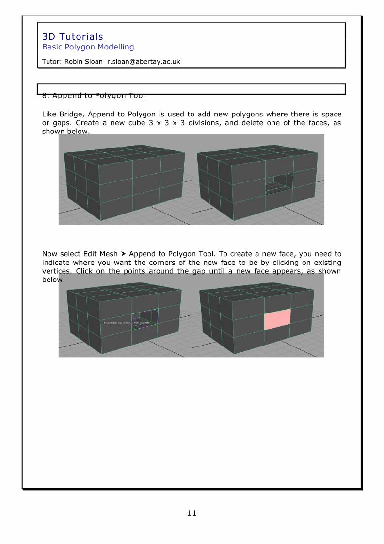
8. Append to Polygon Tool
Like Bridge, Append to Polygon is used to add new polygons where there is space
or gaps. Create a new cube 3 x 3 x 3 divisions, and delete one of the faces, asshown below.
Now select Edit Mesh Append to Polygon Tool. To create a new face, you need to
indicate where you want the corners of the new face to be by clicking on existingvertices. Click on the points around the gap until a new face appears, as shownbelow.
11

8/8/2019 3D Tutorials - Basic Polygon Modelling
http://slidepdf.com/reader/full/3d-tutorials-basic-polygon-modelling 12/14
3D TutorialsBasic Polygon Modelling
Tutor: Robin Sloan [email protected]
9. Wedge and Poke Face
Wedge Face is used to create new geometry extruded from a face around an edge.
Create a new cube, then select a face and an edge on the face, as shown below.
Now go to Edit Mesh Wedge Face . Set Arc angle to 90 and Divisions to 4, then
click apply.
12

8/8/2019 3D Tutorials - Basic Polygon Modelling
http://slidepdf.com/reader/full/3d-tutorials-basic-polygon-modelling 13/14
3D TutorialsBasic Polygon Modelling
Tutor: Robin Sloan [email protected]
As you can see, the new geometry is a wedge extruded from the selected face,
around the selected edge at 90 degrees with four divisions.
Poke face adds a new vertex and corresponding edges to the selection. Try
selecting a face on a cube and clicking Edit Mesh Poke Face to achieve the resultshown below. You can offset the new vertex by going to Edit Mesh Poke Face .
13
8/8/2019 3D Tutorials - Basic Polygon Modelling
http://slidepdf.com/reader/full/3d-tutorials-basic-polygon-modelling 14/14
3D TutorialsBasic Polygon Modelling
Tutor: Robin Sloan [email protected]
14
TASK
Using the polygon primitive shapes, transformation tools, and the polygon editing
tools described in this tutorial, try to model a few of the following objects
• A Small Table
• A Pen
• A Stapler• A Bottle of Wine
• A Hardback Book
• A Desk Lamp• A Flatscreen Television• A Graphics Tablet
• A Kettle
• A Cuddly Toy