3g3mv-p10cdt -e v7 inverter plc - · pdf filev7 inverter plc 377 3g3mv-p10cdt@-e v7 inverter...
TRANSCRIPT
377V7 inverter PLC
3G3MV-P10CDT@-E
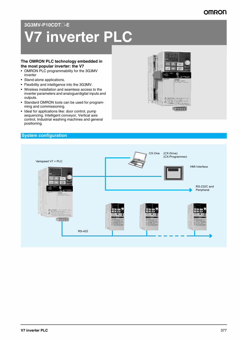
V7 inverter PLCThe OMRON PLC technology embedded in the most popular inverter: the V7 • OMRON PLC programmability for the 3G3MV
inverter• Stand-alone applications.• Flexibility and intelligence into the 3G3MV.• Wireless installation and seamless access to the
inverter parameters and analogue/digital inputs and outputs.
• Standard OMRON tools can be used for program-ming and commissioning.
• Ideal for applications like: door control, pump sequencing, Intelligent conveyor, Vertical axis control, Industrial washing machines and general positioning.
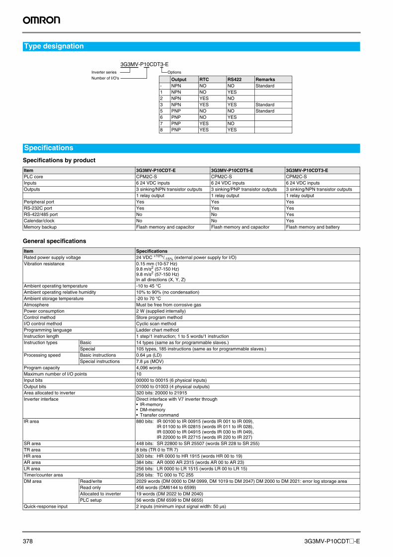
System configuration
Varispeed V7 + PLC
RS-422
RS-232C and
Peripheral
HMI Interface
CX-One (CX-Drive)
(CX-Programmer)
Y203-EN2-02-Katalog.book Seite 377 Mittwoch, 24. Mai 2006 2:22 14
378 3G3MV-P10CDT@-E
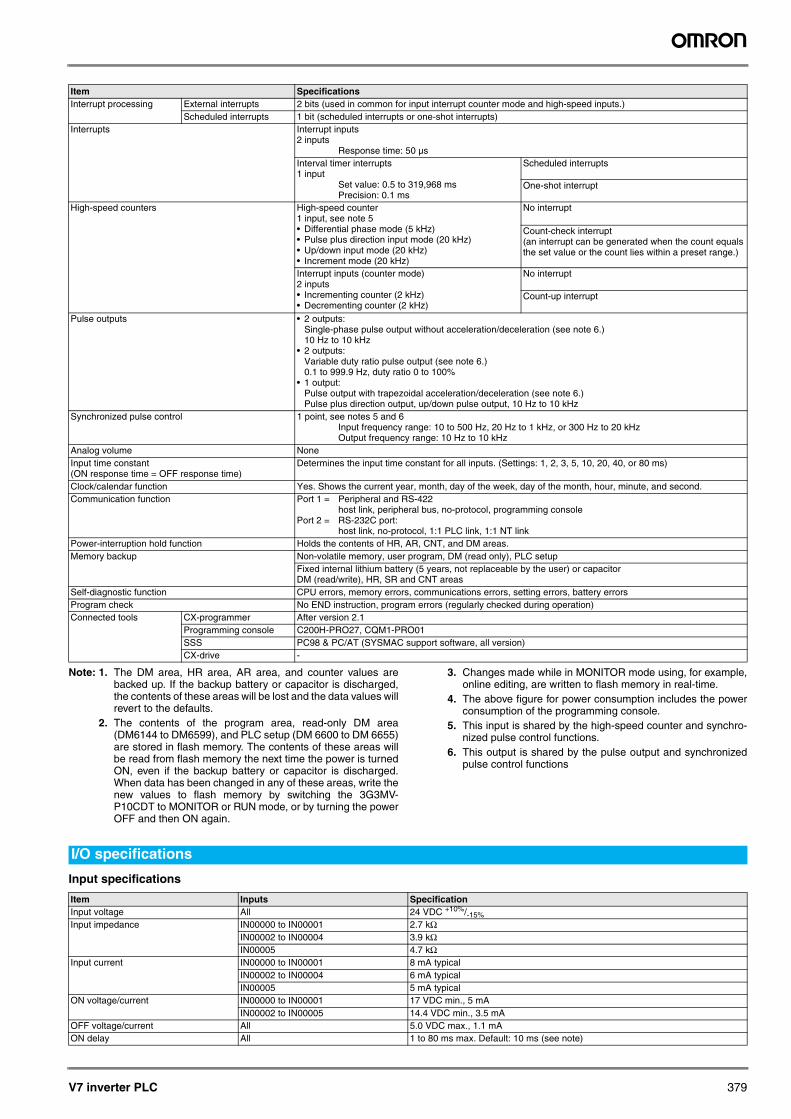
Specifications by product
General specifications
Type designation
Specifications
Item 3G3MV-P10CDT-E 3G3MV-P10CDT5-E 3G3MV-P10CDT3-EPLC core CPM2C-S CPM2C-S CPM2C-SInputs 6 24 VDC inputs 6 24 VDC inputs 6 24 VDC inputsOutputs 3 sinking/NPN transistor outputs 3 sinking/PNP transistor outputs 3 sinking/NPN transistor outputs
1 relay output 1 relay output 1 relay outputPeripheral port Yes Yes YesRS-232C port Yes Yes YesRS-422/485 port No No YesCalendar/clock No No YesMemory backup Flash memory and capacitor Flash memory and capacitor Flash memory and battery
Item SpecificationsRated power supply voltage 24 VDC +10%/-15% (external power supply for I/O)Vibration resistance 0.15 mm (10-57 Hz)
9.8 m/s2 (57-150 Hz)9.8 m/s2 (57-150 Hz)In all directions (X, Y, Z)
Ambient operating temperature -10 to 45 °CAmbient operating relative humidity 10% to 90% (no condensation)Ambient storage temperature -20 to 70 °CAtmosphere Must be free from corrosive gasPower consumption 2 W (supplied internally)Control method Store program methodI/O control method Cyclic scan methodProgramming language Ladder chart methodInstruction length 1 step/1 instruction; 1 to 5 words/1 instructionInstruction types Basic 14 types (same as for programmable slaves.)
Special 105 types, 185 instructions (same as for programmable slaves.) Processing speed Basic instructions 0.64 µs (LD)
Special instructions 7.8 µs (MOV) Program capacity 4,096 wordsMaximum number of I/O points 10Input bits 00000 to 00015 (6 physical inputs)Output bits 01000 to 01003 (4 physical outputs)Area allocated to inverter 320 bits: 20000 to 21915Inverter interface Direct interface with V7 inverter through
• IR-memory• DM-memory• Transfer command
IR area 880 bits: IR 00100 to IR 00915 (words IR 001 to IR 009),IR 01100 to IR 02815 (words IR 011 to IR 028),IR 03000 to IR 04915 (words IR 030 to IR 049),IR 22000 to IR 22715 (words IR 220 to IR 227)
SR area 448 bits: SR 22800 to SR 25507 (words SR 228 to SR 255) TR area 8 bits (TR 0 to TR 7) HR area 320 bits: HR 0000 to HR 1915 (words HR 00 to 19) AR area 384 bits: AR 0000 AR 2315 (words AR 00 to AR 23)LR area 256 bits: LR 0000 to LR 1515 (words LR 00 to LR 15) Timer/counter area 256 bits: TC 000 to TC 255DM area Read/write 2029 words (DM 0000 to DM 0999, DM 1019 to DM 2047) DM 2000 to DM 2021: error log storage area
Read only 456 words (DM6144 to 6599) Allocated to inverter 19 words (DM 2022 to DM 2040) PLC setup 56 words (DM 6599 to DM 6655)
Quick-response input 2 inputs (minimum input signal width: 50 µs)
3G3MV-P10CDT3-EInverter series
Number of I/O's
Options
Output RTC RS422 Remarks- NPN NO NO Standard1 NPN NO YES2 NPN YES NO3 NPN YES YES Standard5 PNP NO NO Standard6 PNP NO YES7 PNP YES NO8 PNP YES YES
Y203-EN2-02-Katalog.book Seite 378 Mittwoch, 24. Mai 2006 2:22 14
V7 inverter PLC 379
Note: 1. The DM area, HR area, AR area, and counter values arebacked up. If the backup battery or capacitor is discharged,the contents of these areas will be lost and the data values willrevert to the defaults.
2. The contents of the program area, read-only DM area(DM6144 to DM6599), and PLC setup (DM 6600 to DM 6655)are stored in flash memory. The contents of these areas willbe read from flash memory the next time the power is turnedON, even if the backup battery or capacitor is discharged.When data has been changed in any of these areas, write thenew values to flash memory by switching the 3G3MV-P10CDT to MONITOR or RUN mode, or by turning the powerOFF and then ON again.
3. Changes made while in MONITOR mode using, for example,online editing, are written to flash memory in real-time.
4. The above figure for power consumption includes the powerconsumption of the programming console.
5. This input is shared by the high-speed counter and synchro-nized pulse control functions.
6. This output is shared by the pulse output and synchronizedpulse control functions
Input specifications
Interrupt processing External interrupts 2 bits (used in common for input interrupt counter mode and high-speed inputs.) Scheduled interrupts 1 bit (scheduled interrupts or one-shot interrupts)
Interrupts Interrupt inputs2 inputs
Response time: 50 µsInterval timer interrupts1 input
Set value: 0.5 to 319,968 msPrecision: 0.1 ms
Scheduled interrupts
One-shot interrupt
High-speed counters High-speed counter1 input, see note 5• Differential phase mode (5 kHz)• Pulse plus direction input mode (20 kHz)• Up/down input mode (20 kHz)• Increment mode (20 kHz)
No interrupt
Count-check interrupt (an interrupt can be generated when the count equals the set value or the count lies within a preset range.)
Interrupt inputs (counter mode)2 inputs• Incrementing counter (2 kHz)• Decrementing counter (2 kHz)
No interrupt
Count-up interrupt
Pulse outputs • 2 outputs: Single-phase pulse output without acceleration/deceleration (see note 6.)10 Hz to 10 kHz
• 2 outputs:Variable duty ratio pulse output (see note 6.)0.1 to 999.9 Hz, duty ratio 0 to 100%
• 1 output:Pulse output with trapezoidal acceleration/deceleration (see note 6.)Pulse plus direction output, up/down pulse output, 10 Hz to 10 kHz
Synchronized pulse control 1 point, see notes 5 and 6Input frequency range: 10 to 500 Hz, 20 Hz to 1 kHz, or 300 Hz to 20 kHzOutput frequency range: 10 Hz to 10 kHz
Analog volume NoneInput time constant (ON response time = OFF response time)
Determines the input time constant for all inputs. (Settings: 1, 2, 3, 5, 10, 20, 40, or 80 ms)
Clock/calendar function Yes. Shows the current year, month, day of the week, day of the month, hour, minute, and second.Communication function Port 1 = Peripheral and RS-422
host link, peripheral bus, no-protocol, programming consolePort 2 = RS-232C port:
host link, no-protocol, 1:1 PLC link, 1:1 NT linkPower-interruption hold function Holds the contents of HR, AR, CNT, and DM areas.Memory backup Non-volatile memory, user program, DM (read only), PLC setup
Fixed internal lithium battery (5 years, not replaceable by the user) or capacitor DM (read/write), HR, SR and CNT areas
Self-diagnostic function CPU errors, memory errors, communications errors, setting errors, battery errorsProgram check No END instruction, program errors (regularly checked during operation)Connected tools CX-programmer After version 2.1
Programming console C200H-PRO27, CQM1-PRO01SSS PC98 & PC/AT (SYSMAC support software, all version)CX-drive -
Item Specifications
I/O specifications
Item Inputs SpecificationInput voltage All 24 VDC +10%/-15%Input impedance IN00000 to IN00001 2.7 kΩ
IN00002 to IN00004 3.9 kΩIN00005 4.7 kΩ
Input current IN00000 to IN00001 8 mA typicalIN00002 to IN00004 6 mA typicalIN00005 5 mA typical
ON voltage/current IN00000 to IN00001 17 VDC min., 5 mAIN00002 to IN00005 14.4 VDC min., 3.5 mA
OFF voltage/current All 5.0 VDC max., 1.1 mAON delay All 1 to 80 ms max. Default: 10 ms (see note)
Y203-EN2-02-Katalog.book Seite 379 Mittwoch, 24. Mai 2006 2:22 14
380 3G3MV-P10CDT@-E
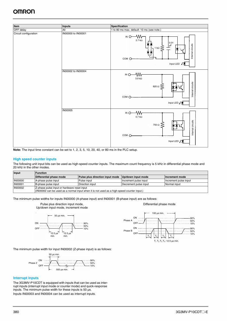
Note: The input time constant can be set to 1, 2, 3, 5, 10, 20, 40, or 80 ms in the PLC setup.
High speed counter inputsThe following unit input bits can be used as high-speed counter inputs. The maximum count frequency is 5 kHz in differential phase mode and 20 kHz in the other modes.
The minimum pulse widths for inputs IN00000 (A-phase input) and IN00001 (B-phase input) are as follows:
The minimum pulse width for input IN00002 (Z-phase input) is as follows:
Interrupt inputsThe 3G3MV-P10CDT is equipped with inputs that can be used as inter-rupt inputs (interrupt input mode or counter mode) and quick-response inputs. The minimum pulse width for these inputs is 50 µs.Inputs IN00003 and IN00004 can be used as interrupt inputs.
OFF delay All 1 to 80 ms max. default: 10 ms (see note.)Circuit configuration IN00000 to IN00001
IN00002 to IN00004
IN00005
Item Inputs Specification
IN
COM
2.7 kW0.01 µF
Input LED
Inte
rnal
circ
uits
1 kW
IN
COM
3.9 kW
Input LED
Inte
rnal
circ
uits
820 W
IN
COM
4.7 kW
Input LED
Inte
rnal
circ
uits
750 W
Input Function
Differential phase mode Pulse plus direction input mode Up/down input mode Increment modeIN00000 A-phase pulse input Pulse input Increment pulse input Increment pulse inputIN00001 B-phase pulse input Direction input Decrement pulse input Normal inputIN00002 Z-phase pulse input or hardware reset input
(IN00002 can be used as a normal input when it is not used as a high-speed counter input.)
Pulse plus direction input mode, Up/down input mode, increment mode
Differential phase mode
50 µs min.
ON
OFF
12.5 µs min.
12.5 µs min.
90% 50% 10%
90% 50% 10%
90% 50% 10%
T1 T2 T3 T4
100 µs min.
ON
OFF
ON
OFF
Phase A
Phase B
T1 T2 T3 T4: 12.5 µs min.
50 µs min.
500 µs min.
ON
OFFPhase Z
90% 50% 10%
Y203-EN2-02-Katalog.book Seite 380 Mittwoch, 24. Mai 2006 2:22 14

V7 inverter PLC 381
Output Specification
Relay output
Note: The service life of relay output contacts shown in the table assumes the worst conditions. The following graph shows the results of OMRON's service life tests at a switching rate of 1,800 times/hour.
Transistor outputs (sinking/NPN)
Note: When using OUT01000 or OUT01001 as a pulse output, connect a dummy resistor as required to bring the load current between 0.01 and 0.1 A. If the load current is below 0.1 A, the ON-to-OFF response time will be longer and high-speed pulses (source-type transistor outputs) will not be output. If the load current is above 0.1 A, the transistor will generate more heat and components may be damaged.
!CautionDo not apply voltage in excess of the maximum switching capacityto an output terminal. It may result in damage to the product or fire
Item SpecificationMaximum switching capacity 2 A, 250 VAC (cosϕ=1)
2A, 24VDCMinimum switching load 10 mA, 5 VDCService life of relay Electrical: 150,000 operations (24 VDC resistive load)
100,000 operations (240 VAC inductive load cosϕ=0.4)Mechanical: 20,000,000 operations
ON delay 15 ms max.OFF delay 15 ms max.Circuit configuration
Item SpecificationMaximum switching capacity 4.5 to 30 VDC, 0.2 A/ outputMinimum switching capacity 0.5 mAMaximum inrush current 0.9 A for 10 msLeakage current 0.1 mAResidual voltage 1.5 V max.ON response time 20 µs max.OFF response time 40 µs max. for 4.5 to 26.4 VDC, 10 to 100 mA
0.1 ms max for 4.5 to 30 VDC, 10 to 200 mAFuse One fuse per output (cannot be replaced by user)Circuit configuration
Output LED
Internal circuits
OUT
COM
OUT
Maximum 250 VAC: 2 A 24 VDC: 2 A
120 VAC, resistive load
24 VDC, τ = 7 ms
120 VAC, cosφ = 0.4
240 VAC, cosφ = 0.4
24 VDC/240 VAC, resistive load
Switching rate: 1,800 times/hour
300
200
100
50
30
20
10
5
3
2
0.1 0.2 0.3 0.5 0.7 1 2 3 5
Contact current (A)
Life (x 104)
Output LED
Internal circuits
OUT
OUT
COM (-)
24 VDC
Y203-EN2-02-Katalog.book Seite 381 Mittwoch, 24. Mai 2006 2:22 14
382 3G3MV-P10CDT@-E
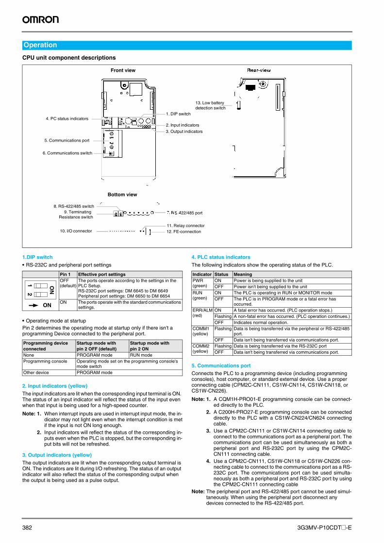
CPU unit component descriptions
1.DIP switch
• RS-232C and peripheral port settings
• Operating mode at startupPin 2 determines the operating mode at startup only if there isn't a programming Device connected to the peripheral port.
2. Input indicators (yellow)
The input indicators are lit when the corresponding input terminal is ON. The status of an input indicator will reflect the status of the input even when that input is being used for a high-speed counter.
Note: 1. When interrupt inputs are used in interrupt input mode, the in-dicator may not light even when the interrupt condition is metif the input is not ON long enough.
2. Input indicators will reflect the status of the corresponding in-puts even when the PLC is stopped, but the corresponding in-put bits will not be refreshed.
3. Output indicators (yellow)
The output indicators are lit when the corresponding output terminal is ON. The indicators are lit during I/O refreshing. The status of an output indicator will also reflect the status of the corresponding output when the output is being used as a pulse output.
4. PLC status indicators
The following indicators show the operating status of the PLC.
5. Communications port
Connects the PLC to a programming device (including programming consoles), host computer, or standard external device. Use a proper connecting cable (CPM2C-CN111, CS1W-CN114, CS1W-CN118, or CS1W-CN226).
Note: 1. A CQM1H-PRO01-E programming console can be connect-ed directly to the PLC.
2. A C200H-PRO27-E programming console can be connecteddirectly to the PLC with a CS1W-CN224/CN624 connectingcable.
3. Use a CPM2C-CN111 or CS1W-CN114 connecting cable toconnect to the communications port as a peripheral port. Thecommunications port can be used simultaneously as both aperipheral port and RS-232C port by using the CPM2C-CN111 connecting cable.
4. Use a CPM2C-CN111, CS1W-CN118 or CS1W-CN226 con-necting cable to connect to the communications port as a RS-232C port. The communications port can be used simulta-neously as both a peripheral port and RS-232C port by usingthe CPM2C-CN111 connecting cable
Note: The peripheral port and RS-422/485 port cannot be used simul-taneously. When using the peripheral port disconnect any devices connected to the RS-422/485 port.
Operation
1. DIP switch4. PC status indicators
2. Input indicators
5. Communications port
6. Communications switch
3. Output indicators
22/485 port
8. RS-422/485 switch9. Terminating
Resistance switch
10. I/O connector11. Relay connector12. FE-connection
13. Low batterydetection switch
Front view
Bottom view
Pin 1 Effective port settingsOFF(default)
The ports operate according to the settings in the PLC Setup.RS-232C port settings: DM 6645 to DM 6649Peripheral port settings: DM 6650 to DM 6654
ON The ports operate with the standard communications settings.
Programming device connected
Startup mode withpin 2 OFF (default)
Startup mode with pin 2 ON
None PROGRAM mode RUN modeProgramming console Operating mode set on the programming console's
mode switchOther device PROGRAM mode
12
ON
ON
Indicator Status MeaningPWR (green)
ON Power is being supplied to the unitOFF Power isn't being supplied to the unit
RUN (green)
ON The PLC is operating in RUN or MONITOR modeOFF The PLC is in PROGRAM mode or a fatal error has
occurred.ERR/ALM (red)
ON A fatal error has occurred. (PLC operation stops.)Flashing A non-fatal error has occurred. (PLC operation continues.)OFF Indicates normal operation.
COMM1 (yellow)
Flashing Data is being transferred via the peripheral or RS-422/485 port.
OFF Data isn't being transferred via communications port.COMM2 (yellow)
Flashing Data is being transferred via the RS-232C portOFF Data isn't being transferred via communications port.
Y203-EN2-02-Katalog.book Seite 382 Mittwoch, 24. Mai 2006 2:22 14
V7 inverter PLC 383
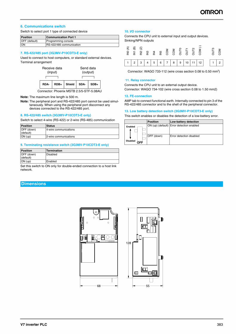
6. Communications switchSwitch to select port 1 type of connected device
7. RS-422/485 port (3G3MV-P10CDT3-E only)
Used to connect to host computers, or standard external devices.Terminal arrangement
Note: The maximum line length is 500 m.Note: The peripheral port and RS-422/485 port cannot be used simul-
taneously. When using the peripheral port disconnect any devices connected to the RS-422/485 port.
8. RS-422/485 switch (3G3MV-P10CDT3-E only)
Switch to select 4-wire (RS-422) or 2-wire (RS-485) communication
9. Terminating resistance switch (3G3MV-P10CDT3-E only)
Set this switch to ON only for double-ended connection to a host link network.
10. I/O connector
Connects the CPU unit to external input and output devices.Sinking/NPN outputs
11. Relay connector
Connects the CPU unit to an external output device.Connector: WAGO 734-102 (wire cross section 0.08 to 1.50 mm2)
12. FE-connection
AMP tab to connect functional earth. Internally connected to pin 3 of the RS-422/485 connector and to the shell of the peripheral connector.
13. Low battery detection switch (3G3MV-P10CDT3-E only)
This switch enables or disables the detection of a low-battery error.
Position Communication Port 1OFF (default) Programming consoleON RS-422/485 communication
Position StatusOFF (down) (default)
4-wire communications
ON (up) 2-wire communications
Position TerminationOFF (down) (default)
Disabled
ON (up) Enabled
RDA- RDB+ Shield SDA- SDB+
Receive data (input)
Send data (output)
Connector: Phoenix MSTB 2.5/5-STF-5.08AU
Position Low-battery detectionON (up) (default) Error detection enabled
OFF (down) Error detection disabled
1 2 3 4 5 6 7 8 9 10 11 12
IN0
(A)
IN1
(B)
IN2
(Z)
IN3
IN4
IN5
CO
M
CO
M
OU
T0
OU
T1
OU
T2
CO
M (
-)
1 2
OU
T3
CO
M
Connector: WAGO 733-112 (wire cross section 0.08 to 0.50 mm2)
OFF
Enabled
Disabled
Dimensions
68
128
55
Y203-EN2-02-Katalog.book Seite 383 Mittwoch, 24. Mai 2006 2:22 14

384 3G3MV-P10CDT@-E
V7 + PLC in positioning application
point-to-point applications are posible adding the PLC to the V7, including the possibility to add position and speed tables or even use recipes that could be select using a HMI
Note: For detailed information about the inverter, please refer to Varispeed V7 section.
V7 + PLC with pump
Using the PLC, it is possible to control a modulated plus several auxiliar pumps according your own parameters and system demand. It is also possible to add a GSM modem to advice about any problem.
Note: For detailed information about the inverter, please see into the Varispeed V7 section.
Applications examples
Speed
Position
Time
EncoderRS-232
Home
Motor
HMI interface
Operation description
V7 + PLC
V7 + PLC
Powersupply
Mainpump
Aux.pump 1
Aux.pump 2
Water
Water
Aux.pump N
Up to 6
Pressuresensor
HMI interface
GSM Modem
Y203-EN2-02-Katalog.book Seite 384 Mittwoch, 24. Mai 2006 2:22 14
V7 inverter PLC 385
V7 inverter PLC
A Varispeed
Note: For detailed information, please refer to Varispeed V7 series section.
B Cables
B Software
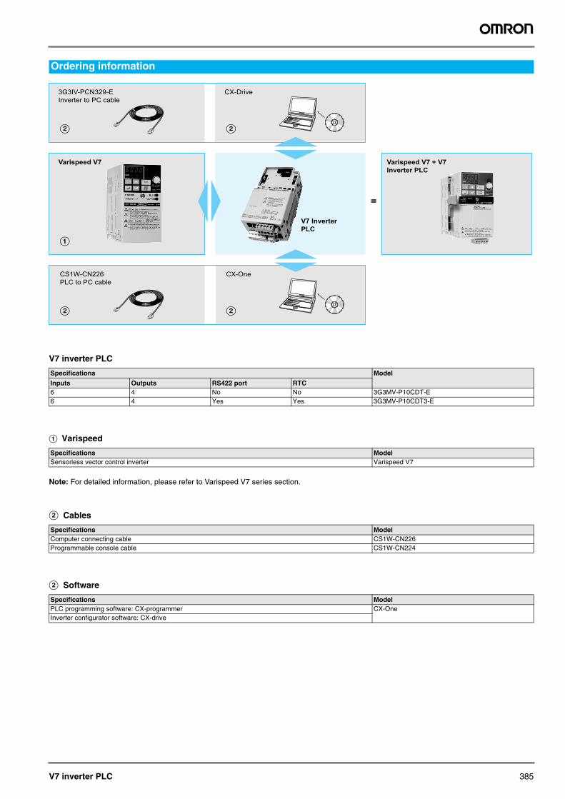
Ordering information
Specifications Model
Inputs Outputs RS422 port RTC6 4 No No 3G3MV-P10CDT-E6 4 Yes Yes 3G3MV-P10CDT3-E
Specifications Model Sensorless vector control inverter Varispeed V7
Specifications Model Computer connecting cable CS1W-CN226Programmable console cable CS1W-CN224
Specifications Model PLC programming software: CX-programmer CX-OneInverter configurator software: CX-drive
B
A
B
3G3IV-PCN329-E
Inverter to PC cable
CX-Drive
V7 Inverter
PLC
Varispeed V7
B B
CS1W-CN226
PLC to PC cable
CX-One
Varispeed V7 + V7
Inverter PLC
=
Y203-EN2-02-Katalog.book Seite 385 Mittwoch, 24. Mai 2006 2:22 14
386 3G3MV-P10CDT@-E
In the interest of product improvement, specifications are subject to change without notice.
ALL DIMENSIONS SHOWN ARE IN MILLIMETERS.
To convert millimeters into inches, multiply by 0.03937. To convert grams into ounces, multiply by 0.03527.
Cat. No. I24E-EN-02
Y203-EN2-02-Katalog.book Seite 386 Mittwoch, 24. Mai 2006 2:22 14