3rd research coordinated meeting on “development and ... · 1. background the crp on...
TRANSCRIPT
F1-RC1023.3
LIMITED DISTRIBUTION
Working Material
3rd Research Coordinated Meeting on “Development and Applications of the
Technique of Residual Stress Measurement in Materials”
Report of the 3rd RCM relevant to the IAEA CRP1314
IAEA, Vienna, Austria, 20-24 April 2009
Reproduced by the IAEA
Vienna, Austria, June 2009
NOTE
The material in this document has been supplied by the authors and has not been edited by the IAEA. The views expressed remain the responsibility of the named authors and do not necessarily reflect those of the government(s) of the designating Member State(s). In particular, neither the IAEA nor any other organization or body sponsoring this meeting can be held responsible for any material reproduced in this document.


FOREWORD
The 3rd and the last RCM of the IAEA CRP on “Development and Application of the technique of Residual Stress Measurement in Materials using Neutrons” was held from 20 to 24 April 2009 at the IAEA, Vienna, Austria. The meeting was attended by 9 participants from Czech Republic, Germany, Hungary, the Netherlands, Romania, Russia, South Africa, and Pakistan, and chaired by Mr Carsten Ohms. The major drafting of the report was done by Mr Andrew Venter. The IAEA officer responsible for this document is Mr Danas Ridikas of the Physics Section, Division of Physical and Chemical Sciences, Department of Nuclear Sciences and Applications.

CONTENTS
1. BACKGROUND .............................................................................................................. 1
2. PROCEEDINGS OF THE MEETING............................................................................. 1
2.1. Carsten Ohms, JRC, Petten, The Netherlands .................................................... 2 2.1.1. Instrument development ......................................................................... 2 2.1.2. Round robin exercises............................................................................. 3
2.2. Pavol Mikula, NPI, v.v.i., Rez, Czech Republic ................................................ 3 2.3. Rainer Schneider, Helmholtz Zentrum Berlin, Germany ................................... 5 2.4. Ion Ionita, INR-Pitesti, Romania ........................................................................ 7 2.5. Gyula Török, BNC, Hungary ............................................................................. 9 2.6. Andrew Venter, NECSA, South Africa............................................................ 10 2.7. Anatoly Balagurov, FLNP, Dubna, Russia....................................................... 12 2.8. Ghulam Shabbir, PINSTECH, Pakistan ........................................................... 14
3. WORKPLAN FOR THE REMAINING TIME OF THE CRP AND BEYOND........... 15
3.1. Round Robin exercises ..................................................................................... 15 3.2. The European Network NeT............................................................................. 16 3.3. STRAINET....................................................................................................... 16 3.4. Table of Contents of the final project publication, deadlines and
responsibilities .................................................................................................. 17
4. DEDICATED DISCUSSION ON ROUND ROBIN EXERCISE ................................. 18
5. RECOMMENDATIONS................................................................................................ 20
6. CONCLUDING SESSION............................................................................................. 21
ANNEX I. MEETING AGENDA ...................................................................................... 22
ANNEX II. LIST OF PARTICIPANTS .............................................................................. 26
ANNEX III. SUMMARY OF ACTIONS, RESPONSIBILITIES AND DEADLINES....... 27
ANNEX IV. TEMPLATE FOR THE FACILITY INFORMATION REQUEST................. 28

1. BACKGROUND
The CRP on “Development and Application of the technique of Residual Stress Measurement in Materials using Neutrons” started in 2006 with five research contracts and four research agreements. The first research coordination meeting (RCM) was held in May 2006 in Vienna to refine research objectives, define collaborations between participants for teamwork, and milestones for the CRP.
The second RCM was held in October 2007 in Berlin to report progress towards researching objectives and milestones with the CRP. Target dates for the completion of the research contracts and research agreements were agreed upon, as well as action plans finalised for the outstanding group work during the meeting. In Berlin the third and the last RCM was scheduled for Q2 2009.
2. PROCEEDINGS OF THE MEETING
The third Research Coordination Meeting (RCM) of the CRP was held during April 20-24, 2009 at the head quarters of the IAEA, Vienna, Austria. The main purpose of the meeting was to review the progress of the work done by the participants during the 2nd phase up to completion of the projects. The Agenda of the meeting is attached (Annex –1). The following participants attended the meeting
[1] Mr Pavol Mikula Czech Republic [2] Mr Rainer Schneider Germany [3] Mr Gyula Török Hungary [4] Mr Carsten Ohms Netherlands [5] Mr Ion Ionita Romania [6] Mr Anatoly Balagurov Russia [7] Mr Andrew Venter South Africa [8] Mr Ghulam Shabbir Pakistan [9] Mr Danas Ridikas IAEA (Scientific Secretary)
Mr A. Das from India could not attend the meeting.
Mr N. Ramamoorthy, DIR-NAPC, welcomed the participants and gave the opening remarks. He also recommended that, due to the high scientific and technological value of the work carried out during this CRP, the final report on the CRP results should be set at the level of a Technical Report Series (TRS) document. Mr G. Mank, Head NAPC / Physics Section, also welcomed the participants and extended his expectation of a fruitful meeting. Mr. Danas Ridikas welcomed the participants, presented the background of the CRP and suggested the following objectives for the meeting:
• Present individual status reports on the work done during the 2nd phase of the project
• Present the status and future actions related to collaborative experiments (round robin)
• Prepare the 3rd RCM report including summary and recommendations
• Prepare the draft report for the final document to be published at the end of this CRP
• Discuss the actions and work-plan for future cooperation after the end of this CRP
1
The names of Mr. Carsten Ohms, Andrew Venter and Pavol Mikula were suggested for the chairperson, rapporteur and facilitator of the meeting, respectively, and were accepted.
The participants then presented the work done during the second phase of the CRP and expectations to completion of the respective projects. The brief summary of the individual country presentations is as follows:
2.1. Carsten Ohms, JRC, Petten, The Netherlands
2.1.1. Instrument development
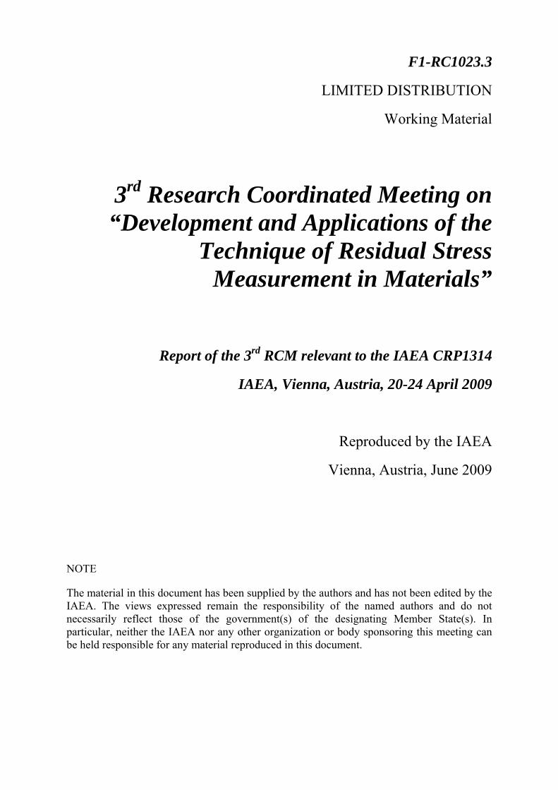
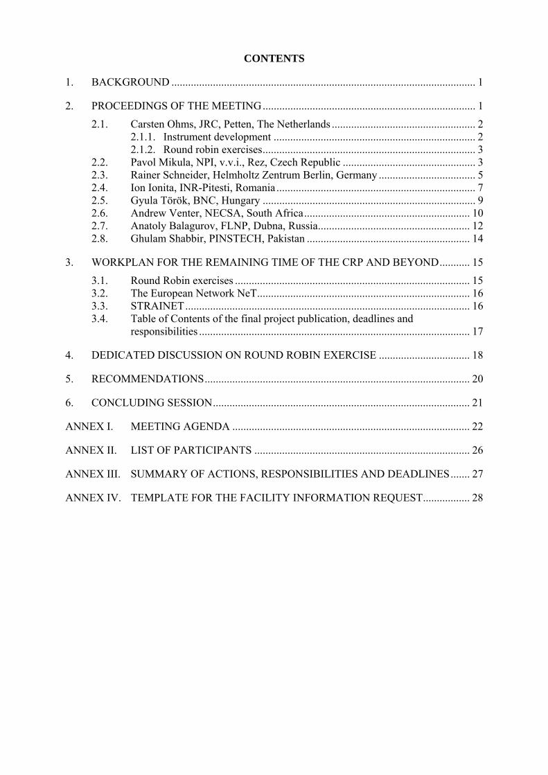
In the period Sep 2005 to Nov 2007 the Joint Research Centre – Institute for Energy has developed and put into operation a new neutron diffractometer for residual stress determination at its beam line HB5 at the High Flux Reactor in Petten. The main objective of the development had been to obtain improvements of the sample positioning stage. These improvements relate to the ranges and accuracy of sample positioning. The new system offers movement ranges of 250 mm in the x, y and z directions. In addition, specimens, including ancillary equipment if applicable, of 200 kg can now be supported by the new positioning stage. All specimen table movements are encoder controlled and a positioning accuracy of 0.1 mm can be reached. A number of successfully executed measurement campaigns demonstrated that the system functions well.
The neutronic performance of the new system has not been changed. A Cu-(111) vertically focusing monochromator is delivering a neutron wavelength of 0.256 nm to the instrument with a flux of about 106 n/cm2/sec. Development work is underway in order to obtain a new monochromator delivering a lower neutron wavelength that would ideally provide access to the low alloy steel (211) and the austenitic steel (311) reflection planes. It is envisaged that an NPI type (double) focusing Si monochromator set-up could deliver such a wavelength, increasing at the same time significantly the performance of the instrument.
FIG. 1 Setting up the new diffractometer at HFR beam tube HB5
Development of instrument control software has proven to be a problematic issue for the JRC. The current software on this instrument has been provided by a commercial supplier, and, while providing a workable solution, the instrument operators have a number of open issues that cannot be fulfilled anymore in the given situation. A better solution for the control of the instrument is still being looked for.
2
2.1.2. Round robin exercises
Two round robin exercises had been agreed to be executed by the participating organizations on their – in many cases new – neutron diffractometers:
a. in the first exercise the objective is to demonstrate the ability to measure a straight line of increasing strain in a specimen subjected to 4-point bending;
b. for the second exercise the VAMAS TWA 20 aluminium ring & plug specimen from the late 1990’s is to be reused.
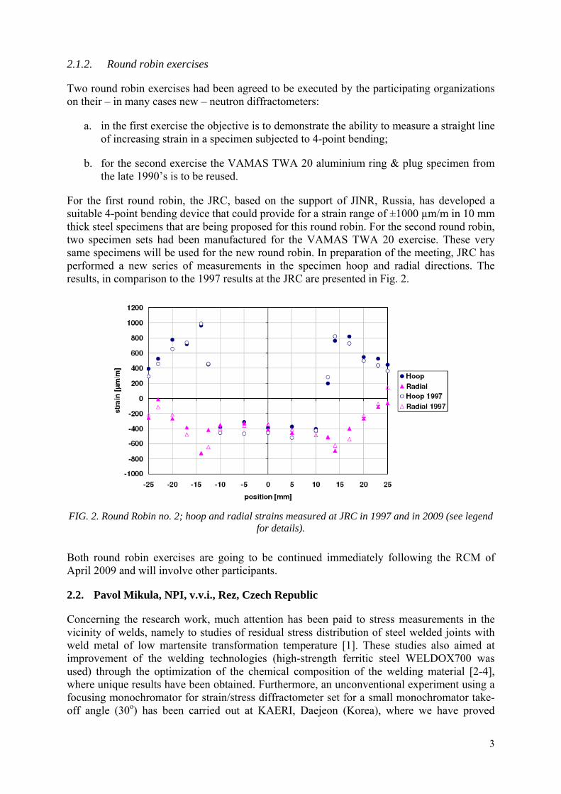
For the first round robin, the JRC, based on the support of JINR, Russia, has developed a suitable 4-point bending device that could provide for a strain range of ±1000 µm/m in 10 mm thick steel specimens that are being proposed for this round robin. For the second round robin, two specimen sets had been manufactured for the VAMAS TWA 20 exercise. These very same specimens will be used for the new round robin. In preparation of the meeting, JRC has performed a new series of measurements in the specimen hoop and radial directions. The results, in comparison to the 1997 results at the JRC are presented in Fig. 2.
FIG. 2. Round Robin no. 2; hoop and radial strains measured at JRC in 1997 and in 2009 (see legend
for details).
Both round robin exercises are going to be continued immediately following the RCM of April 2009 and will involve other participants.
2.2. Pavol Mikula, NPI, v.v.i., Rez, Czech Republic
Concerning the research work, much attention has been paid to stress measurements in the vicinity of welds, namely to studies of residual stress distribution of steel welded joints with weld metal of low martensite transformation temperature [1]. These studies also aimed at improvement of the welding technologies (high-strength ferritic steel WELDOX700 was used) through the optimization of the chemical composition of the welding material [2-4], where unique results have been obtained. Furthermore, an unconventional experiment using a focusing monochromator for strain/stress diffractometer set for a small monochromator take-off angle (30o) has been carried out at KAERI, Daejeon (Korea), where we have proved
3
excellent resolution (at the scattering angle 2θS = 90o, FWHM (∆d/d) = 2.8x10⁻³) and luminosity of the instrument when equipped with a thin (1.3 mm thickness) bent perfect Si(111) slab [5].
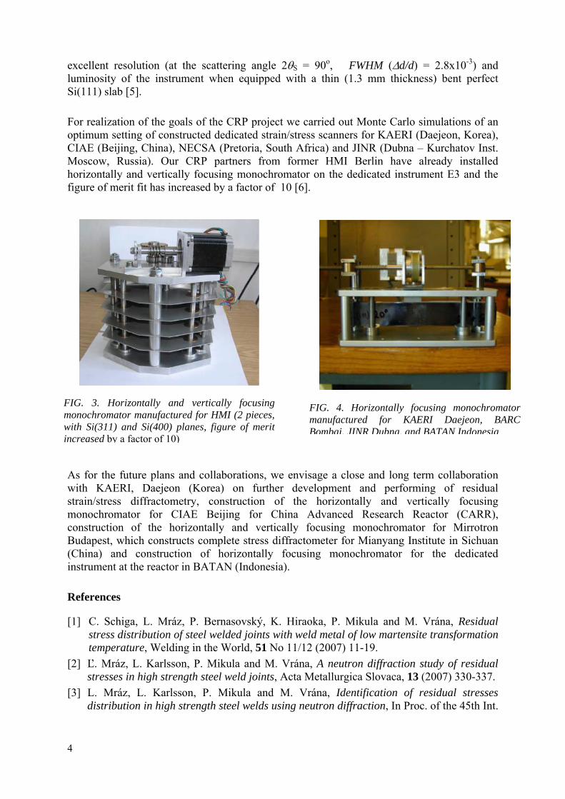
For realization of the goals of the CRP project we carried out Monte Carlo simulations of an optimum setting of constructed dedicated strain/stress scanners for KAERI (Daejeon, Korea), CIAE (Beijing, China), NECSA (Pretoria, South Africa) and JINR (Dubna – Kurchatov Inst. Moscow, Russia). Our CRP partners from former HMI Berlin have already installed horizontally and vertically focusing monochromator on the dedicated instrument E3 and the figure of merit fit has increased by a factor of 10 [6].
FI mo wi inc
FmB
As for the future plans and collaborations, we envisawith KAERI, Daejeon (Korea) on further devestrain/stress diffractometry, construction of the monochromator for CIAE Beijing for China Aconstruction of the horizontally and vertically foBudapest, which constructs complete stress diffractom(China) and construction of horizontally focusininstrument at the reactor in BATAN (Indonesia).
References
[1] C. Schiga, L. Mráz, P. Bernasovský, K. Hiraostress distribution of steel welded joints with weldtemperature, Welding in the World, 51 No 11/12
[2] Ľ. Mráz, L. Karlsson, P. Mikula and M. Vrána, stresses in high strength steel weld joints, Acta M
[3] L. Mráz, L. Karlsson, P. Mikula and M. Vrádistribution in high strength steel welds using neu
4
IG. 4. Horizontally focusing monochromator anufactured for KAERI Daejeon, BARC ombai, JINR Dubna, and BATAN Indonesia
G. 3. Horizontally and vertically focusingnochromator manufactured for HMI (2 pieces,
th Si(311) and Si(400) planes, figure of meritreased by a factor of 10)
ge a close and long term collaboration lopment and performing of residual horizontally and vertically focusing dvanced Research Reactor (CARR), cusing monochromator for Mirrotron eter for Mianyang Institute in Sichuan
g monochromator for the dedicated
ka, P. Mikula and M. Vrána, Residual metal of low martensite transformation (2007) 11-19. A neutron diffraction study of residual etallurgica Slovaca, 13 (2007) 330-337. na, Identification of residual stresses tron diffraction, In Proc. of the 45th Int.
Conf. Experimental Stress Analysis EAN 2007, June 4-7, 2007, Hotel Výhledy, Czech Rep.
[4] P. Mikula, M. Vrána, Ľ. Mráz and L. Karlsson, High-resolution neutron diffraction employing Bragg diffraction optics - A tool for advanced nondestructive testing of materials, In Proc. Biennial ASME Conference on Engineering Systems Design and Analysis (ESDA 2008), 7 to 9 July 2008, Haifa, CD-ROM, paper ESDA2008-59174.
[5] V. Em, P. Mikula and B. S. Seong, Highly efficient strain/stress diffractometer operating at small take-off angle, publication is under preparation.
[6] R.C. Wimpory, P. Mikula, J. Šaroun, T. Poeste, J. Li, M. Hoffmann and R. Schneider, Efficiency Boost of the Materials Science Diffractometer E3 at BENSC: One order of magnitude due to a double focusing monochromator, Neutron News, 19 (2008) 16-19.
2.3. Rainer Schneider, Helmholtz Zentrum Berlin, Germany
At the research reactors BER II and FRM II current developments are focused on improving reliability, repeatability and convenience of the neutron instruments, experiments and data evaluation. Increasing the overall effectiveness of a neutron instrument means optimizing the experiment outcome per beam time used. Besides sophisticated hardware developments for sample manipulation and automation of experimental procedures, like instrument alignment, this can be solved by automatic intelligent instrument control systems enabling data pre-evaluation that abolish blind measurements.
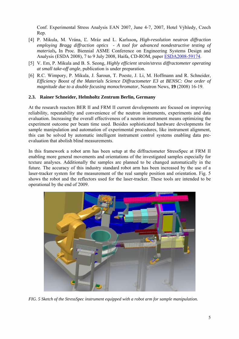
In this framework a robot arm has been setup at the diffractometer StressSpec at FRM II enabling more general movements and orientations of the investigated samples especially for texture analyses. Additionally the samples are planned to be changed automatically in the future. The accuracy of this industry standard robot arm has been increased by the use of a laser-tracker system for the measurement of the real sample position and orientation. Fig. 5 shows the robot and the reflectors used for the laser-tracker. These tools are intended to be operational by the end of 2009.
FIG. 5 Sketch of the StressSpec instrument equipped with a robot arm for sample manipulation.
5
The automatic instrument alignment system developed at HZB during 2004-2006 has been improved and is now included within the new instrument control software framework OpenInspire that is being developed within a close cooperation between HZB, FRM II, JRC Petten and Open University/UK. This novel open-source control software exhibits a strict modular design and enables the handling of large data sets and very general scan modes. Due to its platform independency and the absence of restrictions concerning interfaces this software platform can be used at many facilities enabling a common development of instrument control software, measurement, calibration and benchmarking procedures.
Thanks to the availability of powerful computers with huge memory it became possible to change the data acquisition modes from step scanning to list-mode or time-stamp data. For example a continuous movement of the sample during a texture measurement improves the quality of the result significantly compared to the conventional discrete data collection mode. All orientations of the sample are considered during the measurement and the data reduction can be done based on the complete dataset and taking into account intensity gradients.
In 2007 the STRAINET kick-off meeting took place in Berlin and the participants ended up with an agreement that a first common interface can basically be realized as a common data format. The NeXus format has been considered. The next step here is the definition of a special NeXus Data format (name space) for the residual stress neutron experiments.
End of 2007 the new monochromator system has been installed at E3. It has been developed in close cooperation with Pavol Mikula and Jan Saroun from NPI Rez (Czech Republic). The efficiency of E3 has been increased by approximately a factor of 13 mainly due to the optimized peak width that is accessible by this type of monochromator, what is especially well suited for the application in residual stress analysis. Thus the instrument exhibits an overall efficiency comparable to the well known instruments at the high-flux reactors.
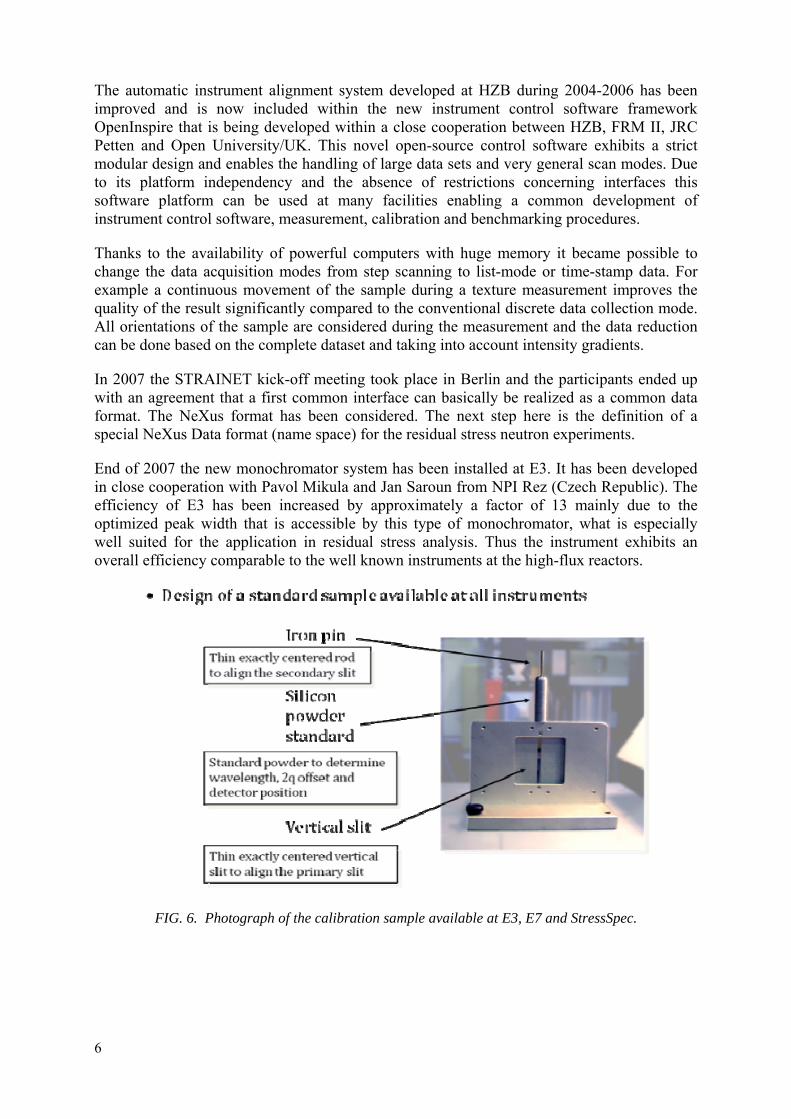
FIG. 6. Photograph of the calibration sample available at E3, E7 and StressSpec.
6
2.4. Ion Ionita, INR-Pitesti, Romania
The initial work plan was discussed and established at the 1st CRP meeting (Vienna, 2006). It included: - Development of the methodology of stress determination in focusing configurations- realised
during the 2nd and 3rd year of contract - Theoretical study of the optimal configurations of the reactor core suited both for in-pile
irradiation and for neutron scattering experiments-realised during the 3rd year of the contract - Realization of the improved pneumatic bending system-realised during the 1st year of the
contract - Increase of the angular positioning precision using special designed DC motors working as step
by step mode - realised during the 1st year of contract - Realization of the modified self-control system of the instrument, suited for stress determination,
partially realized till now; estimated to be fully accomplished by the end of June - Completion of the position sensitive detector system-realised in the 3rd year of contract. The following components were manufactured, during the 2nd year of contract: a) Sample holding system allowing its movement in x, y, and z directions b) System defining the incident and diffracted beam shape respectively, which is formed by
variable Cd window and Cd small coarse-collimator c) Shielding with variable cadmium window for a position sensitive detector
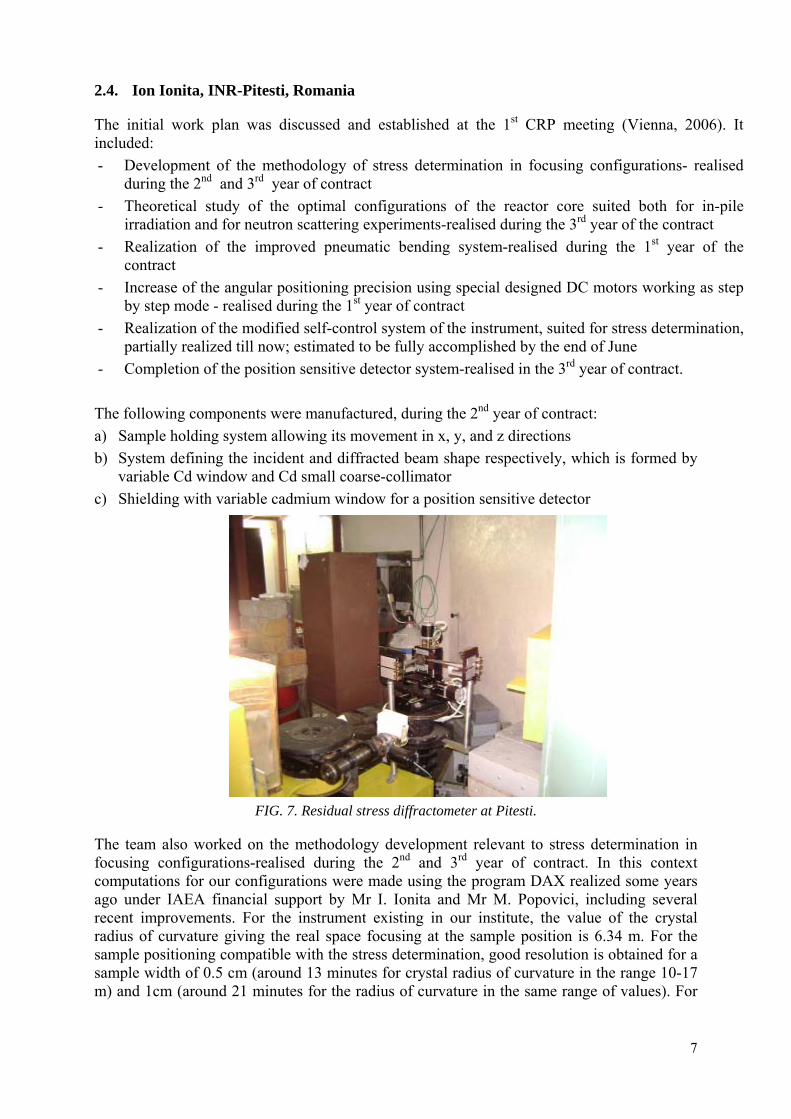
FIG. 7. Residual stress diffractometer at Pitesti.
The team also worked on the methodology development relevant to stress determination in focusing configurations-realised during the 2nd and 3rd year of contract. In this context computations for our configurations were made using the program DAX realized some years ago under IAEA financial support by Mr I. Ionita and Mr M. Popovici, including several recent improvements. For the instrument existing in our institute, the value of the crystal radius of curvature giving the real space focusing at the sample position is 6.34 m. For the sample positioning compatible with the stress determination, good resolution is obtained for a sample width of 0.5 cm (around 13 minutes for crystal radius of curvature in the range 10-17 m) and 1cm (around 21 minutes for the radius of curvature in the same range of values). For
7
larger sample widths the resolution is quite poor. One notes that for symmetrical transmission, the resolution is somewhat better than for symmetrical reflection.
It is interesting to point out also that in these situations the beam width at the sample position is rather small (around 0.5 cm) and practically the same for all the values of curvature radius of interest. A rather smooth dependence of the beam width at sample position on the crystal radius of curvature can be explained if we consider the second term (the “free term”) in the expression for the beam width at the sample position which cannot be compensated; if this term is quite significant (and this is the case for our configuration for which L1 is quite large - around 3 m) the dependence of the beam width on Rm is considerably smoothed. One concludes that it is a good option in the case of space scan for the induced stress determination to choose the step of 0.5-1 cm.
The work done for the period 2008/01/31 – 2009:
− The theoretical study of the optimal configurations of the reactor core suited both for in-pile irradiation and for neutron scattering experiments.
− Develop an Improved Self-Control System for the DR1 High Resolution Focusing Neutron Crystal Diffractometer Operation-to be fully realized at the end of June.
− Completion of the position sensitive detector system-realised in the 3-rd year of contract.
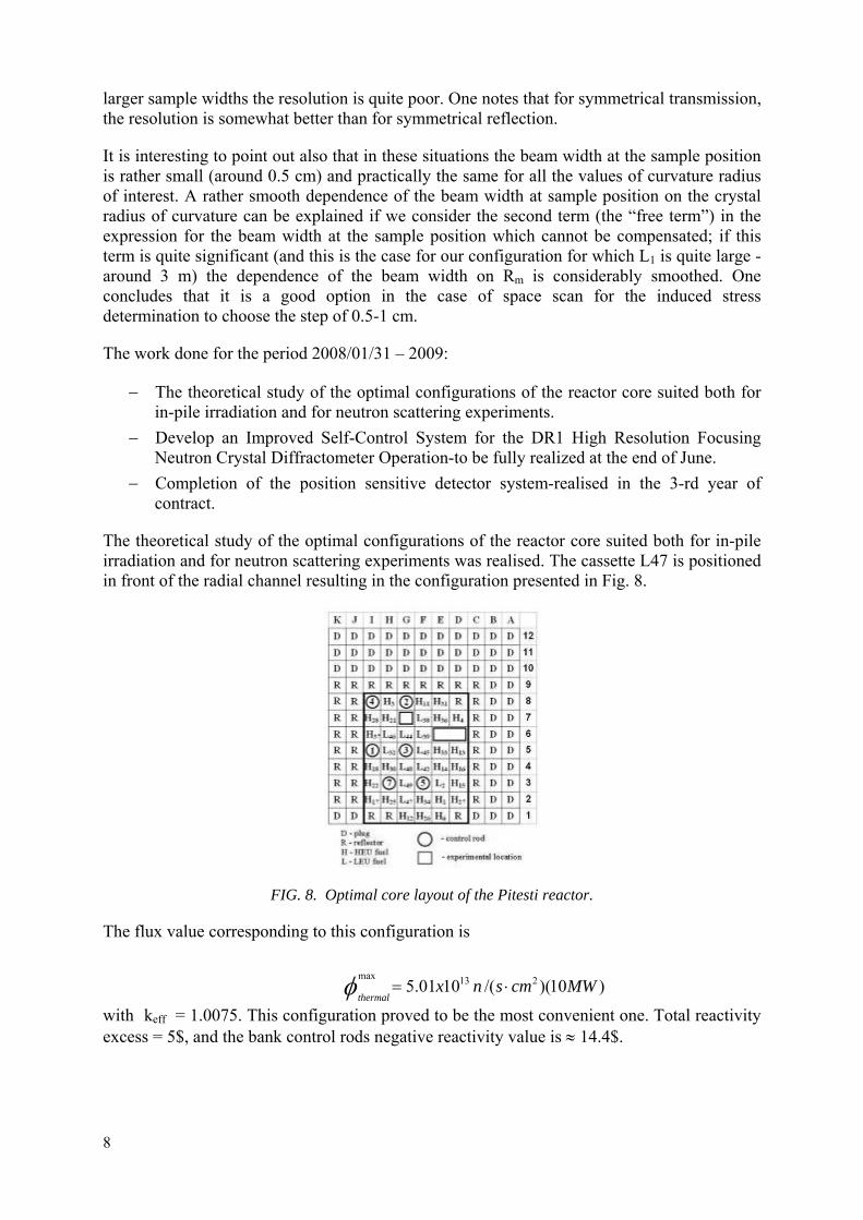
The theoretical study of the optimal configurations of the reactor core suited both for in-pile irradiation and for neutron scattering experiments was realised. The cassette L47 is positioned in front of the radial channel resulting in the configuration presented in Fig. 8.
FIG. 8. Optimal core layout of the Pitesti reactor.
The flux value corresponding to this configuration is
)10)(/(1001.5 213maxMWcmsnx
thermal⋅=φ
with keff = 1.0075. This configuration proved to be the most convenient one. Total reactivity excess = 5$, and the bank control rods negative reactivity value is ≈ 14.4$.
8

For the improvement of Self-Control System for the DR1 High Resolution Focusing Neutron Crystal Diffractometer Operation, the following new modules were realised:
1. The Positioning System of SampleModule 2. The module corresponding to System of Control and Setting Pressure on Crystal 3. The module corresponding to System of Position Sensitive Neutron Detectors
These modules are to be incorporated into the main control system shortly.
2.5. Gyula Török, BNC, Hungary
For the remaining reporting period the installation of radial collimator with necessary movement before 2D detector was planned. The mechanics and electronics now work properly, while some programming still needs improvements to obtain better results (i.e. flat background). The measured collimator transparency is ~ 85 %, the background is reduced by a factor of 2 as shown in Fig. 9. On the combined furnace (Fig. 10) the tensile test at room temperature has been successful, while heat test should be repeated due to the furnace failure. The problems of neutron parasitic scattering have been resolved.
The following results were obtained during the 2nd phase of the project:
• The details of electronics were finalised for the movement automation; user guide remains to be prepared
• The hardware of in-situ tensile stress and heating furnace has been manufactured and tested mechanically; heating elements need additional revision
• The beam formation of Bp5 of NECSA with a “Vitess” program was modelled in the frame of cooperation with NECSA, what adds to the initially proposed collaboration/team work during the work plan
• Testing TOF with Si single crystal filter l=160 mm; fast flux reduction 14 times; factor 2 of loss of long wavelength neutrons
• Electronics for automation of X Y movement is installed.
Status and proposed remaining action plan:
• m ) is under installation (a small deviation
•
•
Area detector for TOF machine (600x800 m 2
of efficiency (~20%) should be decreased • Development of radial collimator is nearly finished • Development and construction of furnace with internal load frame for tensile test is in
progress - cold test already performed Instrumental modelling results using SIMRES program – with further assistance by
Šaroun REZ – is now available • Participation in Round robin 1 and 2 are expected by the end of 2009 The user guide for automatic XY movement is to be prepared, equally for the
movement in Z direction. • Trial measurements of radioactive samples for residual stress are also planned in 2009
9
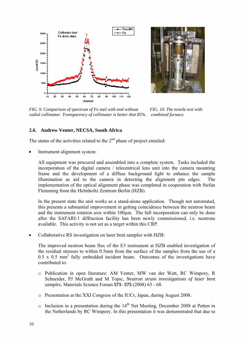
FIG. 9. Comparison of spectrum of Fe nail with and without FIG. 10. The tensile test with radial collimator. Transparency of collimator is better that 85%. combined furnace.
2.6. Andrew Venter, NECSA, South Africa
The status of the activities related to the 2nd phase of project entailed:
• Instrument alignment system:
All equipment was procured and assembled into a complete system. Tasks included the incorporation of the digital camera / telecentrical lens unit into the camera mounting frame and the development of a diffuse background light to enhance the sample illumination as aid to the camera in detecting the alignment pin edges. The implementation of the optical alignment phase was completed in cooperation with Stefan Flemming from the Helmholtz Zentrum Berlin (HZB).
In the present state the unit works as a stand-alone application. Though not automated, this presents a substantial improvement in getting coincidence between the neutron beam and the instrument rotation axis within 100µm. The full incorporation can only be done after the SAFARI-1 diffraction facility has been newly commissioned, i.e. neutrons available. This activity is not set as a target within this CRP.
• Collaborative RS investigation on laser bent samples with HZB:
The improved neutron beam flux of the E3 instrument at HZB enabled investigation of the residual stresses to within 0.5mm from the surface of the samples from the use of a 0.5 x 0.5 mm2 fully embedded incident beam. Outcomes of the investigations have contributed to:
o Publication in open literature: AM Venter, MW van der Watt, RC Wimpory, R Schneider, PJ McGrath and M Topic, Neutron strain investigations of laser bent samples, Materials Science Forum 571- 575 (2008) 63 - 68.
o Presentation at the XXI Congress of the IUCr, Japan, during August 2008.
o Inclusion in a presentation during the 14th Net Meeting, December 2008 at Petten in the Netherlands by RC Wimpory. In this presentation it was demonstrated that due to
10
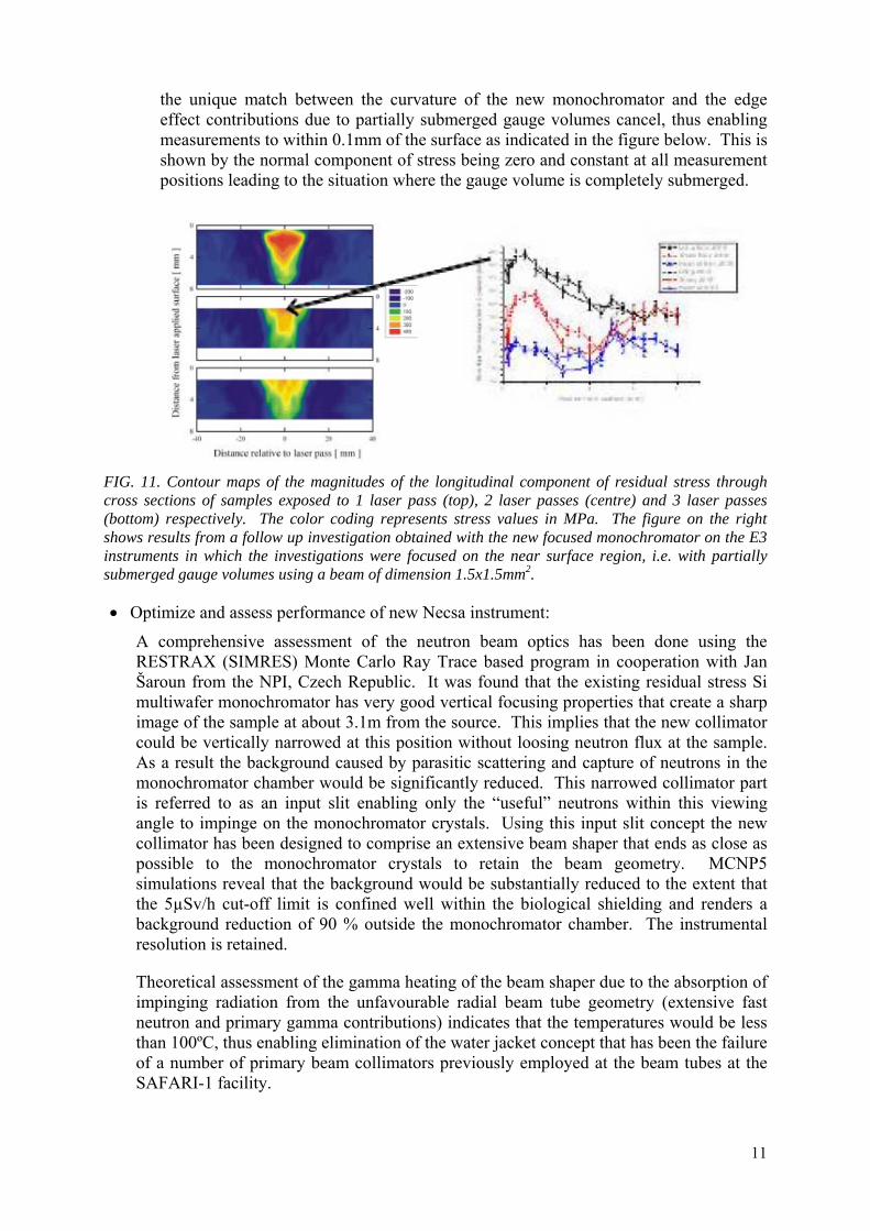
the unique match between the curvature of the new monochromator and the edge effect contributions due to partially submerged gauge volumes cancel, thus enabling measurements to within 0.1mm of the surface as indicated in the figure below. This is shown by the normal component of stress being zero and constant at all measurement positions leading to the situation where the gauge volume is completely submerged.
FIG. 11. Contour maps of the magnitudes of the longitudinal component of residual stress through cross sections of samples exposed to 1 laser pass (top), 2 laser passes (centre) and 3 laser passes (bottom) respectively. The color coding represents stress values in MPa. The figure on the right shows results from a follow up investigation obtained with the new focused monochromator on the E3 instruments in which the investigations were focused on the near surface region, i.e. with partially submerged gauge volumes using a beam of dimension 1.5x1.5mm2.
• Optimize and assess performance of new Necsa instrument:
A comprehensive assessment of the neutron beam optics has been done using the RESTRAX (SIMRES) Monte Carlo Ray Trace based program in cooperation with Jan Šaroun from the NPI, Czech Republic. It was found that the existing residual stress Si multiwafer monochromator has very good vertical focusing properties that create a sharp image of the sample at about 3.1m from the source. This implies that the new collimator could be vertically narrowed at this position without loosing neutron flux at the sample. As a result the background caused by parasitic scattering and capture of neutrons in the monochromator chamber would be significantly reduced. This narrowed collimator part is referred to as an input slit enabling only the “useful” neutrons within this viewing angle to impinge on the monochromator crystals. Using this input slit concept the new collimator has been designed to comprise an extensive beam shaper that ends as close as possible to the monochromator crystals to retain the beam geometry. MCNP5 simulations reveal that the background would be substantially reduced to the extent that the 5µSv/h cut-off limit is confined well within the biological shielding and renders a background reduction of 90 % outside the monochromator chamber. The instrumental resolution is retained.
Theoretical assessment of the gamma heating of the beam shaper due to the absorption of impinging radiation from the unfavourable radial beam tube geometry (extensive fast neutron and primary gamma contributions) indicates that the temperatures would be less than 100ºC, thus enabling elimination of the water jacket concept that has been the failure of a number of primary beam collimators previously employed at the beam tubes at the SAFARI-1 facility.
11
Remaining work (e.g. Round Robin)
• Measurement of a single Bragg peak from the 2mm steel needle embedded in open primary and secondary neutron beams as comparison to the performance and basic parameter comparison of the other instruments in the program
• Investigation of the four-point bending of Al plate
• Investigation of the VAMAS/RESTAND Al ring& plug.
Acknowledgements
IAEA for expert inputs, Rainer Schneider, Robert Wimpory, Jan Šaroun and Gyula Török.
2.7. Anatoly Balagurov, FLNP, Dubna, Russia
At the IBR-2 reactor, stress measurements can be realized with three instruments. Two of them utilize the correlation Fourier technique and the third one is a conventional time-of-flight machine. At both Fourier diffractometers, the reverse time-of-flight method for data acquisition is used and the IAEA Research Contract No. 13737 “Application of Reverse Time-of-Flight (RTOF) Neutron Diffraction for Residual Stress Investigations” is oriented for the further development of this technique at the IBR-2 reactor.
During the last year in the frame of the Research Contract the following work was performed at the High Resolution Fourier Diffractometer (HRFD) and Fourier Stress Diffractometer (FSD) instruments.
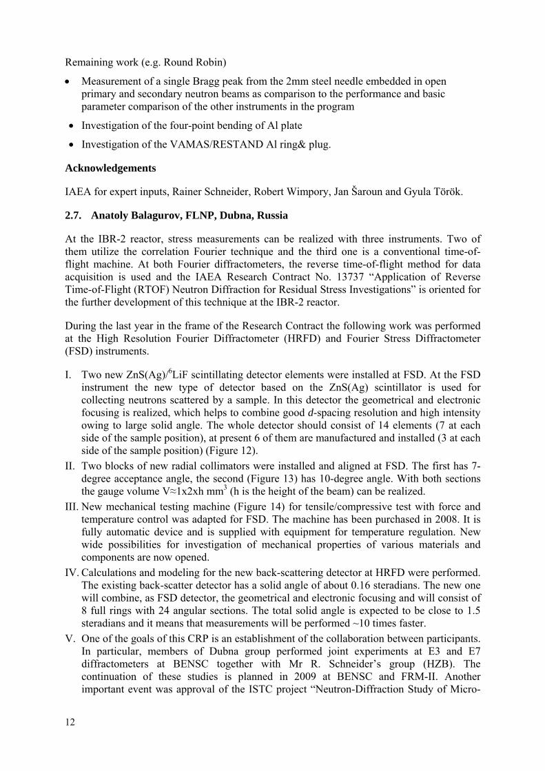
I. Two new ZnS(Ag)/6LiF scintillating detector elements were installed at FSD. At the FSD instrument the new type of detector based on the ZnS(Ag) scintillator is used for collecting neutrons scattered by a sample. In this detector the geometrical and electronic focusing is realized, which helps to combine good d-spacing resolution and high intensity owing to large solid angle. The whole detector should consist of 14 elements (7 at each side of the sample position), at present 6 of them are manufactured and installed (3 at each side of the sample position) (Figure 12).
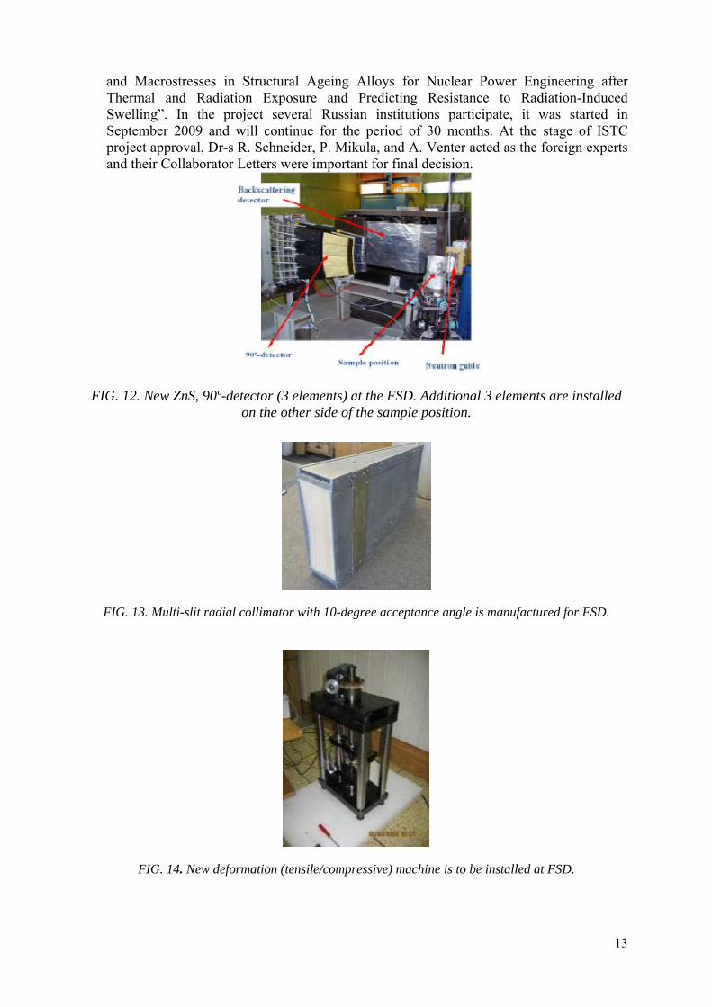
II. Two blocks of new radial collimators were installed and aligned at FSD. The first has 7- degree acceptance angle, the second (Figure 13) has 10-degree angle. With both sections the gauge volume V≈1x2xh mm3 (h is the height of the beam) can be realized.
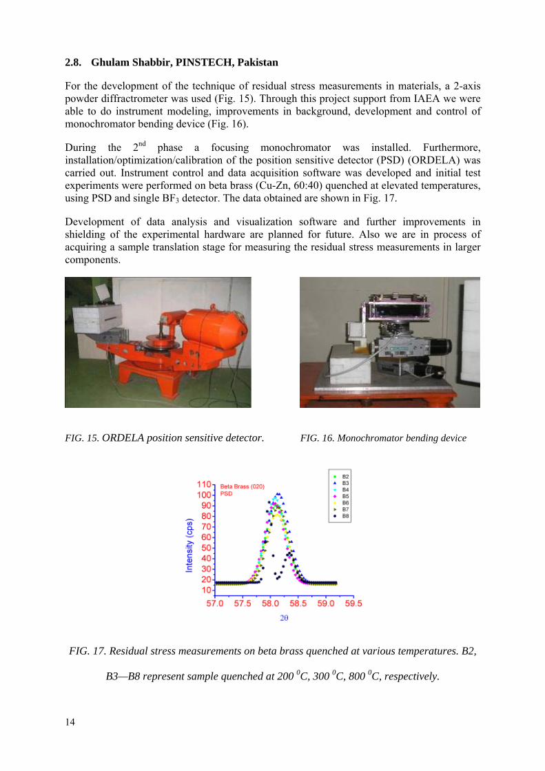
III. New mechanical testing machine (Figure 14) for tensile/compressive test with force and temperature control was adapted for FSD. The machine has been purchased in 2008. It is fully automatic device and is supplied with equipment for temperature regulation. New wide possibilities for investigation of mechanical properties of various materials and components are now opened.
IV. Calculations and modeling for the new back-scattering detector at HRFD were performed. The existing back-scatter detector has a solid angle of about 0.16 steradians. The new one will combine, as FSD detector, the geometrical and electronic focusing and will consist of 8 full rings with 24 angular sections. The total solid angle is expected to be close to 1.5 steradians and it means that measurements will be performed ~10 times faster.
V. One of the goals of this CRP is an establishment of the collaboration between participants. In particular, members of Dubna group performed joint experiments at E3 and E7 diffractometers at BENSC together with Mr R. Schneider’s group (HZB). The continuation of these studies is planned in 2009 at BENSC and FRM-II. Another important event was approval of the ISTC project “Neutron-Diffraction Study of Micro-
12
and Macrostresses in Structural Ageing Alloys for Nuclear Power Engineering after Thermal and Radiation Exposure and Predicting Resistance to Radiation-Induced Swelling”. In the project several Russian institutions participate, it was started in September 2009 and will continue for the period of 30 months. At the stage of ISTC project approval, Dr-s R. Schneider, P. Mikula, and A. Venter acted as the foreign experts and their Collaborator Letters were important for final decision.
FIG. 12. New ZnS, 90º-detector (3 elements) at the FSD. Additional 3 elements are installed on the other side of the sample position.
FIG. 13. Multi-slit radial collimator with 10-degree acceptance angle is manufactured for FSD.
FIG. 14. New deformation (tensile/compressive) machine is to be installed at FSD.
13
2.8. Ghulam Shabbir, PINSTECH, Pakistan
For the development of the technique of residual stress measurements in materials, a 2-axis powder diffractrometer was used (Fig. 15). Through this project support from IAEA we were able to do instrument modeling, improvements in background, development and control of monochromator bending device (Fig. 16).
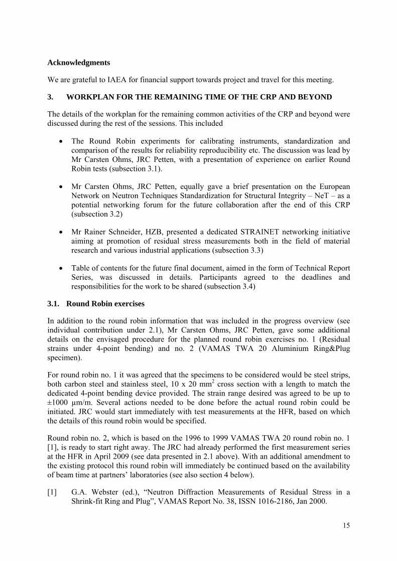
During the 2nd phase a focusing monochromator was installed. Furthermore, installation/optimization/calibration of the position sensitive detector (PSD) (ORDELA) was carried out. Instrument control and data acquisition software was developed and initial test experiments were performed on beta brass (Cu-Zn, 60:40) quenched at elevated temperatures, using PSD and single BF3 detector. The data obtained are shown in Fig. 17.
Development of data analysis and visualization software and further improvements in shielding of the experimental hardware are planned for future. Also we are in process of acquiring a sample translation stage for measuring the residual stress measurements in larger components.
FIG. 15. ORDELA position sensitive detector. FIG. 16. Monochromator bending device
FIG. 17. Residual stress measurements on beta brass quenched at various temperatures. B2,
B3—B8 represent sample quenched at 200 0C, 300 0C, 800 0C, respectively.
14
Acknowledgments
We are grateful to IAEA for financial support towards project and travel for this meeting.
3. WORKPLAN FOR THE REMAINING TIME OF THE CRP AND BEYOND
The details of the workplan for the remaining common activities of the CRP and beyond were discussed during the rest of the sessions. This included
• The Round Robin experiments for calibrating instruments, standardization and comparison of the results for reliability reproducibility etc. The discussion was lead by Mr Carsten Ohms, JRC Petten, with a presentation of experience on earlier Round Robin tests (subsection 3.1).
• Mr Carsten Ohms, JRC Petten, equally gave a brief presentation on the European Network on Neutron Techniques Standardization for Structural Integrity – NeT – as a potential networking forum for the future collaboration after the end of this CRP (subsection 3.2)
• Mr Rainer Schneider, HZB, presented a dedicated STRAINET networking initiative aiming at promotion of residual stress measurements both in the field of material research and various industrial applications (subsection 3.3)
• Table of contents for the future final document, aimed in the form of Technical Report Series, was discussed in details. Participants agreed to the deadlines and responsibilities for the work to be shared (subsection 3.4)
3.1. Round Robin exercises
In addition to the round robin information that was included in the progress overview (see individual contribution under 2.1), Mr Carsten Ohms, JRC Petten, gave some additional details on the envisaged procedure for the planned round robin exercises no. 1 (Residual strains under 4-point bending) and no. 2 (VAMAS TWA 20 Aluminium Ring&Plug specimen).
For round robin no. 1 it was agreed that the specimens to be considered would be steel strips, both carbon steel and stainless steel, 10 x 20 mm2 cross section with a length to match the dedicated 4-point bending device provided. The strain range desired was agreed to be up to ±1000 µm/m. Several actions needed to be done before the actual round robin could be initiated. JRC would start immediately with test measurements at the HFR, based on which the details of this round robin would be specified.
Round robin no. 2, which is based on the 1996 to 1999 VAMAS TWA 20 round robin no. 1 [1], is ready to start right away. The JRC had already performed the first measurement series at the HFR in April 2009 (see data presented in 2.1 above). With an additional amendment to the existing protocol this round robin will immediately be continued based on the availability of beam time at partners’ laboratories (see also section 4 below).
[1] G.A. Webster (ed.), “Neutron Diffraction Measurements of Residual Stress in a Shrink-fit Ring and Plug”, VAMAS Report No. 38, ISSN 1016-2186, Jan 2000.
15
3.2. The European Network NeT
Carsten Ohms presented the structure and the activities within the European Network NeT (the European Network on Neutron Techniques Standardization for Structural Integrity) [1, 2] that has been active since 2002. NeT is a contribution in-kind type of collaboration, where all participating organizations are themselves responsible for the funding of their technical/scientific contributions. NeT has been built around the application of neutron beam based techniques to structural integrity related problems for nuclear power plant components or relevant manufacturing processes. Currently NeT has 4 Task Groups that are assessing residual stresses in steel welds that are supposed to be model cases for real applications. A 5th Task Group employs Small Angle Neutron Scattering to thermal ageing phenomena in duplex stainless steel materials.
While being built around neutron methods, NeT encompasses strong contributions from other technical areas. The whole cycle of specimen manufacturing and materials procurement is covered within the network, including instrumented welding to provide calibration data for numerical welding analyses. Comprehensive materials characterization programmes ensure the availability of materials data for numerical stress assessment. Residual stresses are measured by neutron diffraction, but also by several complementary techniques that can be offered by the partners within NeT. Finally, there are several organizations that perform the numerical analyses of the welding residual stresses.
NeT currently features some 40 participating organizations from industry and academia, including the majority of neutron beam facilities in Europe.
[1] C. Ohms, R.V. Martins, O. Uca, A.G. Youtsos, P.J. Bouchard, M. Smith, M. Keavey, S.K. Bate, P. Gilles, R.C. Wimpory, L. Edwards, “The European Network on Neutron Techniques Standardization for Structural Integrity – NeT”, in: Proceedings of ASME PVP 2008, Chicago, USA, July 27-31, 2008, ASME, CD Publication, 2008, Order No. I795CD, ISBN 0-7918-3828-5.
[2] International Journal of Pressure Vessels and Piping, issue dedicated to NeT Task Group 1 containing 14 contributed papers, Vol. 86, No. 1, 2009.
3.3. STRAINET
The STRAINET networking activity, established in 2006, aims to enhance the neutron instrument’s reliability, experimental repeatability and convenience of use by common development, validation and harmonization of techniques, procedures and tools for residual stress and texture analysis using neutrons. STRAINET intends to facilitate pooling of neutron instruments in order to enable fast access for industry. Facility pooling requires harmonization of data- and protocol formats. Thus the first step on globalizing the activity that originally was started as informal co-operation between HZB, FRM-II, JRC, PSI and NPI is the definition of a dedicated NeXus data format. Additionally internationally coordinated public relation initiatives will support dissemination of information about the techniques within the local engineering and political communities.
Having established the “standardization of interfaces” STRAINET aims in the development of an intelligent "expert-like" tool for experiment planning and instrument control enabling on-line data evaluation, enhanced self-optimizing scan modes for stress- and texture analysis. This tools can be based on the OpenInspire system, a strictly modular framework for the
16
development of an “intelligent” user interface being currently developed at HZB (in close cooperation with FRM II, JRC Petten(NL) and Open University (UK)). This system can be either plugged on the various instrument control systems or adapted as stand-alone. This three year project is funded by HMI, FRM II and JRC.
3.4. Table of Contents of the final project publication, deadlines and responsibilities
The following table of contents of the final project publication in the form of a Technical Report Series (TRS), including sharing of responsibilities for specific tasks, was proposed and agreed upon during the meeting:
1. Introduction – Venter*, Schneider, Ohms a. Residual stress measurement by neutron diffraction b. Complementary techniques
2. Experimental Technique a. Neutron sources – Balagourov b. Types of instruments – Shabbir c. “Standard” equipment – Ohms d. Instrument commissioning / benchmarking – Venter e. Instrument alignment/calibration – Schneider, Ohms f. Measurement procedure – Ohms g. Auxiliary equipment – Torok, Schneider, Mikula, Ohms h. Advanced instrumentation – Mikula, Schneider, Ionita, Balagourov i. Instrument simulation and optimization – Mikula, Ionita, Venter j. Virtual experiments – Schneider
3. Instrument Control and data acquisition – Schneider, Balagourov, Torok 4. Data analysis – Balagourov, Schneider, Torok 5. Industrial applications - Schneider, Ohms, Mikula 6. Future developments – Schneider, Ohms, Balagourov 7. Conclusions – Venter, Ohms, Schneider 8. References - all 9. Appendices
• individual country reports - all • examples of industrial applications - Schneider • human resource development - Shabbir • round robin’s report - Ohms • list of facilities and their characteristics – Ridikas • list of relevant conferences – all
Targeted deadlines:
• individual country reports will be finalised by September 2009
• 1st draft with all contributions will be ready by November 2009
• Consultancy Meeting to finalise the report is planned for the beginning of 2010.
Other remarks:
* - underlined stands for the leading responsible contributor, the main body of TRS should be limited to ~100 pages, the entire document might reach ~200 pages.
17
4. DEDICATED DISCUSSION ON ROUND ROBIN EXERCISE
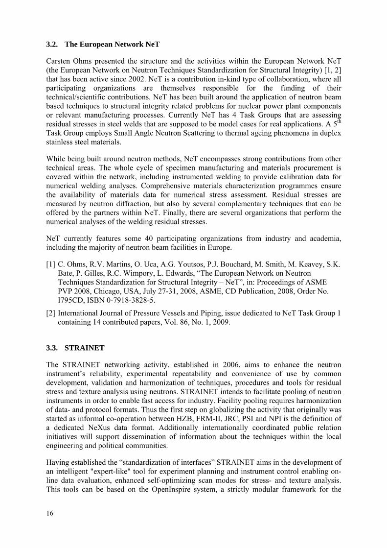
Taking into account the presentations given on the subject of the round robin exercises, it was agreed that both exercises would be started/continued immediately following this meeting. Some preparation work was still necessary for the real start of round robin no.1. JRC had manufactured a dedicated 4-point bending device (see Fig. 18), but functionality tests remain to be performed. These will be done at the JRC using a carbon steel strip as a specimen. Based on these tests the protocol will be drafted by the JRC prior to the beginning of the round robin.
FIG. 18. 4-point bending device for round robin exercise no. 1
NPI and BNC, with assistance from the IAEA, have offered to investigate the possibility of manufacturing a second (back-up) 4-point bending device to facilitate the round robin execution. JRC will provide NPI and BNC with the manufacturing drawings, and decisions will be taken after their in-house investigations.
Furthermore, JRC will investigate the possibility of finding suitable stainless austenitic steel for this round robin as well. No further suggestions have been made by the meeting participants on this issue.
HZB will provide identical iron pins that will be used by all participating laboratories as reference (calibration) samples prior to the round robin exercise. It is attempted to obtain comparable lattice parameter values from the round robin exercise from the different facilities.
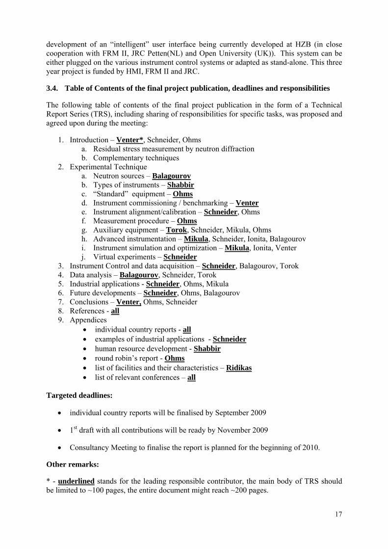
Round robin no.2, the VAMAS TWA 20 Aluminium ring & plug sample (see Fig. 19), is ready to be started right now. JRC has already performed measurements and their data are presented in Fig. 2. The experimental protocol exists from the old VAMAS exercise. The JRC will provide a short amendment to this protocol to give emphasis on the particularities that resulted from the measurement experience obtained from the specimens themselves.
The following laboratories have indicated their availability for the round robin exercise still within the year 2009: HZB, ANSTO, FRM-II, BNC and NPI. A schedule for the
18
measurements will be agreed with these laboratories subsequent to the meeting. For the facility at the PAAR-1 reactor in Pakistan careful planning of the exercise will be necessary as their current operation schedule only foresees very short periods of operation. FLNP, INR-Pitesti and SAFARI are not expected to have operational facilities within the year 2009, but will join into the round robins later.
Carsten Ohms will compile the round robin results obtained by the participating laboratories and provide a preliminary report by the end of 2009, to be discussed and included in the final TRS of the project.
FIG. 19.Aluminium shrink fit Ring&Plug specimens for round robin exercise no. 2
19
5. RECOMMENDATIONS
Based on the discussion on current status and future needs in the domain of residual stress measurements using neutron beams the participants formulated the following recommendations to the IAEA:
• Support and coordinate publication of TRS document as an output of this CRP In this respect, a Consultancy Meeting was recommended early 2010 to finalise the TRS report, discuss ongoing Round Robin results, plan common networking activities beyond this CRP
• Establish the envisaged new CRP on “Development, Characterization and Testing of Materials in Nuclear Energy Sector Using Neutron Beams” A new CRP further exploiting the work initiated in this CRP is strongly recommended. In addition to other methods like SANS and neutron radiography, neutron diffraction is a front-runner technique for the non-destructive determination of residual stresses and qualification of bulk materials, especially welded structures, reactor fuels and structural materials, including high temperature, high pressure environment, presence of electric/magnetic fields and high neutron fluxes. Larger representation from the member states to the proposed CRP should be targeted, including institutions working on numerical modelling in material research.
• Support Education and Training initiatives in Residual Stress assessment by neutron diffraction In this respect, a dedicated Satellite Meeting during the International Research Reactor Conference 2011 was strongly supported. Enabling attendance of developing countries to NeT workshops thematically along with this CRP objectives e.g. on instrument modeling and virtual experiments was suggested. Finally, organization of thematic schools for scientists/engineers to familiarize them with neutron diffraction residual stress and applications similar to the ICTP modalities was proposed.
• Promote and support the networking activities in the area of residual stress analysis using neutrons The creation and management of the STRAINET (harmonization of interfaces and common public relations initiatives, necessary to facilitate service for industrial partners) web page and dedicated end-user targeted leaflet was strongly recommended. Holding of a Consultancy Meeting on the harmonization of data formats and interfaces was suggested. Finally, in kind promotion and support for ongoing NeT activities (advanced experimental and numerical techniques to solve structural integrity related problems in nuclear energy production components) was recommended.
• Organize an end-user targeted IAEA Technical Meeting on “Specific Applications of RRs: Industrial Use of Neutron Beams” The following areas of applications were listed: the fields of oil exploration industry, energy, transportation, food, medical, chemistry, materials industry, geology, civil engineering, cultural heritage, etc.
20

6. CONCLUDING SESSION
Tfo
he meeting concluded with a vote of thanks to Mr Danas Ridikas, the Scientific Secretary, r the arrangement and success of the meeting. The participants thanked the IAEA for
organising the RCMs under this CRP. Equally, the Scientific Secretary thanked all participants for their valuable contribution to this meeting and the entire CRP.
21
ANNEX I. MEETING AGENDA
Agenda of the 3rd RCM of the IAEA CRP1314 on “Development and applications of the technique of residual stress measurements in materials”
20-24 April 2009 Meeting room A-04-78
Agency’s Headquarters, Vienna, Austria
Monday, 20 April 2009
09:00-09:30 Registration, Gate 1
09:30-10:30 Welcome & Opening Remarks
Mr N. Ramamoorthy (Director, NAPC)
Mr G. Mank (Head, NAPC / Physics Section)
Mr D. Ridikas (Scientific Secretary)
Selection of the Chairperson, Rapporteur, Facilitator
Approval of the Agenda
Goals of the Meeting, Mr D. Ridikas, IAEA
10:30-11:00 Break
Session No 1:
Progress reports, current activities, action plans related to Research Agreements, 45 min each
11:00-11:45 Mr Carsten Ohms, JRC Petten, the Netherlands
11:45-12:30 Mr Pavol Mikula, NPI, Czech Replublic
12:30-14:00 Lunch Break
Session No 1 (continued):
Progress reports, current activities, action plans related to Research Agreements, 45 min each
14:00-14:45 Mr Rainer Schneider, HCB, Germany
14:45-15:30 Mr Ion Ionita, INR, Romania
15:30-16:00 Break
16:00-17:00 All, Discussion, Summary
22
Tuesday, 21 April 2009
Session No. 2:
Progress reports, current activities, action plans related to Research Contracts, 45 min each
09:00-09:45 Mr Gyula Torok, BNRC, Hungary
09:45-10:30 Mr Andrew Venter, NECSA, South Africa
10:30-11:00 Break
11:00-11:45 Mr Anatoly Balagurov, JINR, Russia
11:45-12:30 Mr Ghulam Shabbir, PAEC, Pakistan
12:30-14:00 Lunch Break
Session No. 3:
Common actions (round robin), progress report, current activities, action plans
14:00-14:45 Mr Carsten Ohms, JRC Petten, the Netherlands
14:45-15:30 All, Discussion, Summary
15:30-16:00 Break
Session No. 4:
Common actions (networks, collaborations)
16:00-16:30 Mr Carsten Ohms, JRC Petten, the Netherlands
16:30-17:00 Mr Rainer Schneider, HCB, Germany
17:00-18:00 All, Discussion, Summary
19:00 - Hospitality event
Wednesday, 22 April 2009
Session No. 5:
Remaining individual work to be done with respect to the contractual milestones & deliverables; drafting of tasks and time needed to finalise, ~10 min each
09:00-10:30 All, Discussion
10:30-11:00 Break
23
Session No. 6:
Remaining group work (e.g. round robin) to be done with respect to the contractual milestones & deliverables; drafting of tasks and time needed to finalise, ~10 min each
11:00-12:30 All, Discussion
12:30-14:00 Lunch Break
Session No. 7:
Actions and work-plan for future cooperation after the end of this CRP (e.g. creation of networks, initiation of new CRP, etc.), ~10min each
14:00-15:30 All, Discussion
15:30-16:00 Break
Session No. 8:
Preparation of the RCM report, collection of individual summaries, drafting of common summary & recommendations
16:00-17:30 All, Discussion, Editing
Thursday, 23 April 2009
Session No. 8 (continued):
Preparation of the RCM report: finalizing common summary & recommendations
09:00-10:30 All, Discussion, Editing
10:30-11:00 Break
Session No. 9:
Preparation of the final TRS: drafting of contents, collection of individual reports, distribution of responsibilities
11:00-12:30 All, Discussion, Editing
12:30-14:00 Lunch Break
24
Session No9 (continued):
Preparation of the final TRS: drafting the introduction and summary
14:00-15:30 All, Discussion, Editing
15:30-16:00 Break
16:00-17:30 All, Discussion, Editing
Friday, 24 April 2009
Session No9 (continued):
Preparation of the final TRS: finalization of the introduction and summary
09:00-10:30 All, Discussion, Editing
10:30-11:00 Break
Session No10:
Summary of the meeting, final remarks, wrap up
11:00-12:30 All, Discussion
12:30- End of the meeting, lunch, departure
25
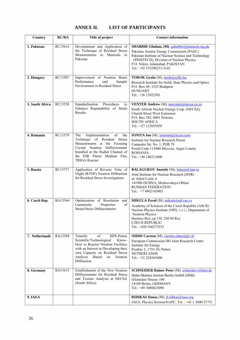
ANNEX II. LIST OF PARTICIPANTS
Country RC/RA Title of project Contact information
1. Pakistan RC13614 Development and Application of the Technique of Residual Stress Measurements in Materials in Pakistan
SHABBIR Ghulam, (M), [email protected] Atomic Energy Commission (PAEC) Pakistan Institute of Nuclear Science and Technology
(PINSTECH); Division of Nuclear Physics P.O. Nilore, Islamabad, PAKISTAN Tel.: +92 519290231/3142
2. Hungary RC13507 Improvement of Neutron Beam Performance and Sample Environment in Residual Stress
TOROK Gyula (M), [email protected] Institute for Solid, State Physics and Optics P.O. Box 49, 1525 Budapest HUNGARY Tel.: +36 13922501
3. South Africa RC13558 Standardisation Procedures to Enhance Repeatability of Strain Results
VENTER Andrew (M), [email protected] African Nuclear Energy Corp. (NECSA) Church Street West Extension P.O. Box 582, 0001 Pretoria SOUTH AFRICA Tel.: +27 123055038
4. Romania RC13579 The Implementation of the Technique of Residual Stress Measurements at the Focusing Crystal Neutron Diffractometer Installed at the Radial Channel of the INR Pitesti Medium Flux TRIGA Reactor
IONITA Ion (M), [email protected] for Nuclear Research Pitesti Campului Str, No. 1, POB 78 Postal Code 115400 Mioveni, Arges County ROMANIA Tel.: +40 248213400
5. Russia RC13737 Application of Reverse Time of Flight (RTOF) Neutron Diffraction for Residual Stress Investigations
BALAGUROV Anatoly (M), [email protected] Institute for Nuclear Research (JINR) ul. Joliot-Curie, 6 141980 DUBNA, Moskovskaya Oblast RUSSIAN FEDERATION Tel.: +7 4962165803
6. Czech Rep. RA13564 Optimization of Resolution and Luminosity Properties of Strain/Stress Diffractometer
MIKULA Pavol (M), [email protected] of Sciences of the Czech Republic (ASCR) Nuclear Physics Institute (NPI), v.v.i.; Department of Neutron Physics Husinec-Rez, cp.130, 250 68 Rez CZECH REPUBLIC Tel.: +420 266273553
7. Netherlands RA13584 Transfer of HFR-Petten Scientific/Technological Know-How to Reactor Neutron Facilities with an Interest in Developing their own Capacity on Residual Stress Analysis Based on Neutron Diffraction
OHMS Carsten (M), [email protected] Commission DG Joint Research Centre Institute for Energy Postbus 2, 1755 ZG Petten NETHERLANDS Tel.: +31 224565400
8. Germany RA13615 Establishment of the New Neutron Diffractometer for Residual Stress and Texture Analysis at NECSA (South Africa)
SCHNEIDER Rainer Peter (M), [email protected] Berlin GmbH (HMI) Glienicker Strasse 100 14109 Berlin, GERMANY Tel.: +49 3080623096
9. IAEA RIDIKAS Danas (M), [email protected], Physics Section/NAPC, Tel. : +41 1 2600 21751
26
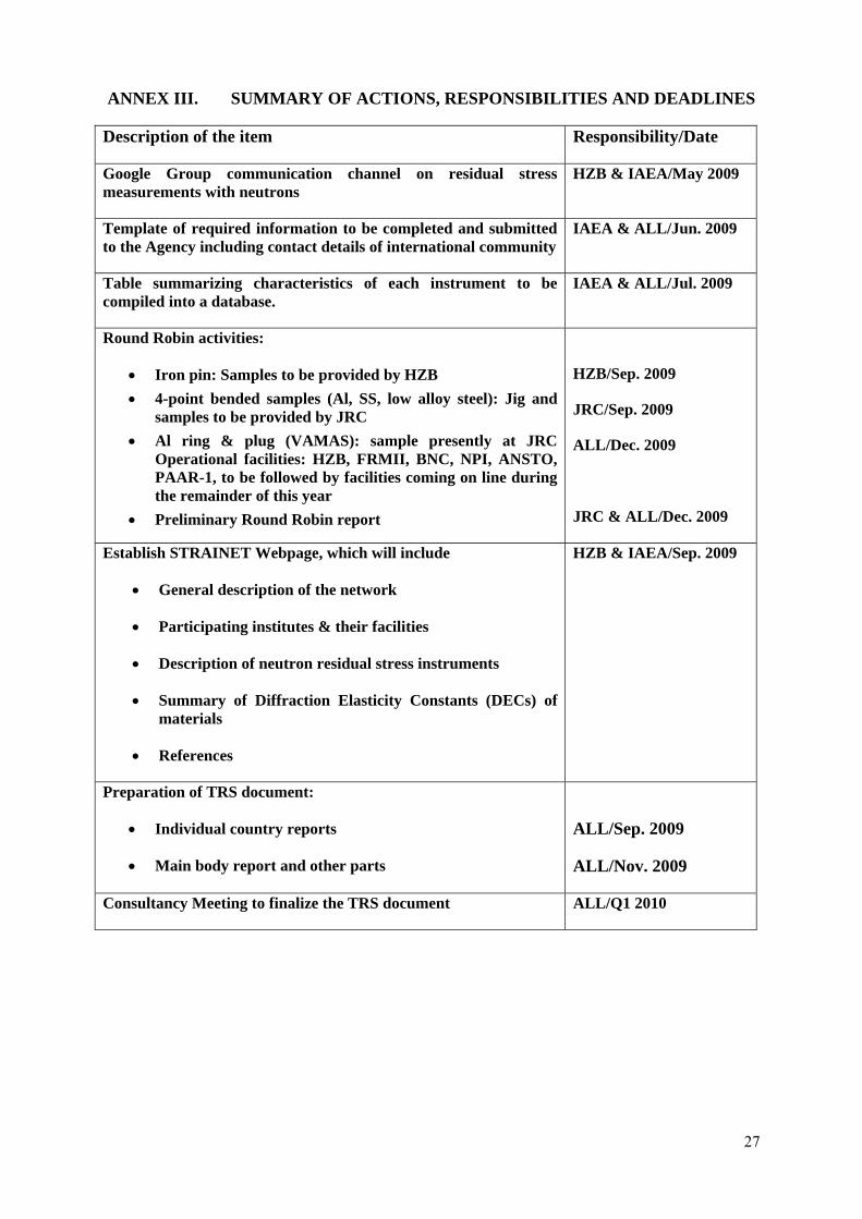
ANNEX III. SUMMARY OF ACTIONS, RESPONSIBILITIES AND DEADLINES
Description of the item Responsibility/Date
Google Group communication channel on residual stress measurements with neutrons
HZB & IAEA/May 2009
Template of required information to be completed and submitted to the Agency including contact details of international community
IAEA & ALL/Jun. 2009
Table summarizing characteristics of each instrument to be compiled into a database.
IAEA & ALL/Jul. 2009
Round Robin activities:
• Iron pin: Samples to be provided by HZB • 4-point bended samples (Al, SS, low alloy steel): Jig and
samples to be provided by JRC • Al ring & plug (VAMAS): sample presently at JRC
Operational facilities: HZB, FRMII, BNC, NPI, ANSTO, PAAR-1, to be followed by facilities coming on line during the remainder of this year
• Preliminary Round Robin report
HZB/Sep. 2009
JRC/Sep. 2009
ALL/Dec. 2009
JRC & ALL/Dec. 2009
Establish STRAINET Webpage, which will include
• General description of the network
• Participating institutes & their facilities
• Description of neutron residual stress instruments
• Summary of Diffraction Elasticity Constants (DECs) of materials
• References
HZB & IAEA/Sep. 2009
Preparation of TRS document:
• Individual country reports
• Main body report and other parts
ALL/Sep. 2009
ALL/Nov. 2009
Consultancy Meeting to finalize the TRS document ALL/Q1 2010
27
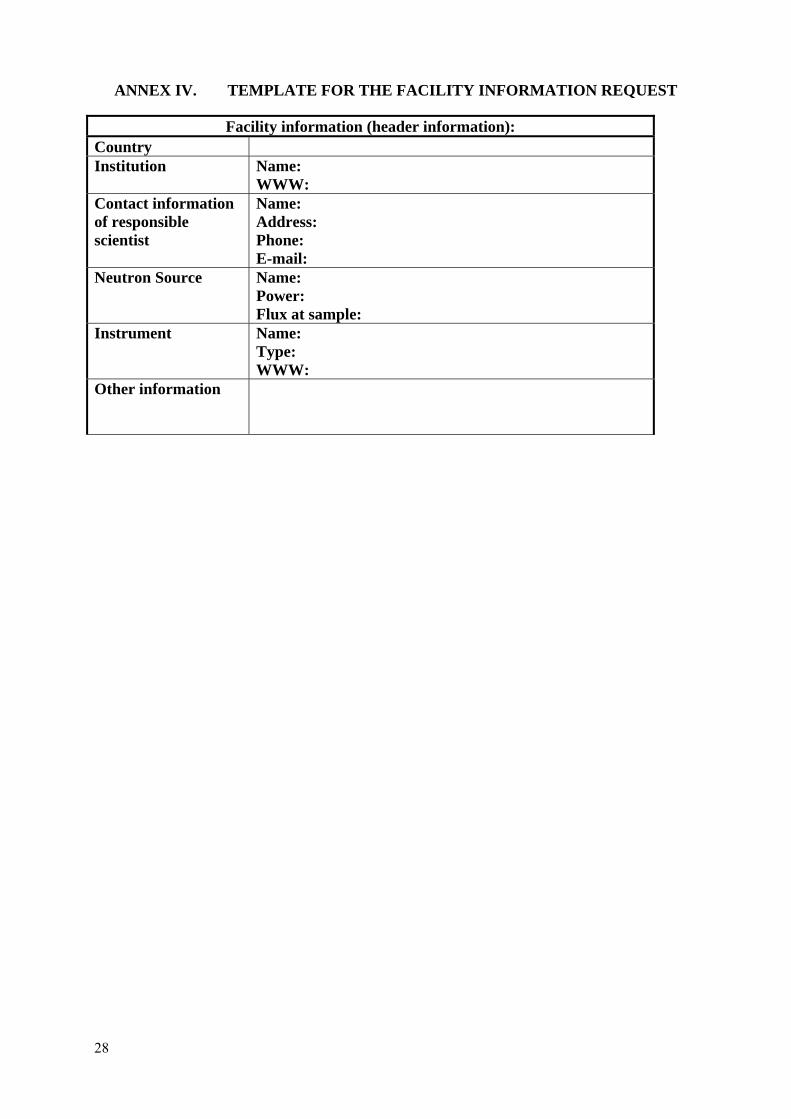
ANNEX IV. TEMPLATE FOR THE FACILITY INFORMATION REQUEST
Facility information (header information): Country Institution
Name: WWW:
Contact information of responsible scientist
Name: Address: Phone: E-mail:
Neutron Source Name: Power: Flux at sample:
Instrument Name: Type: WWW:
Other information
28
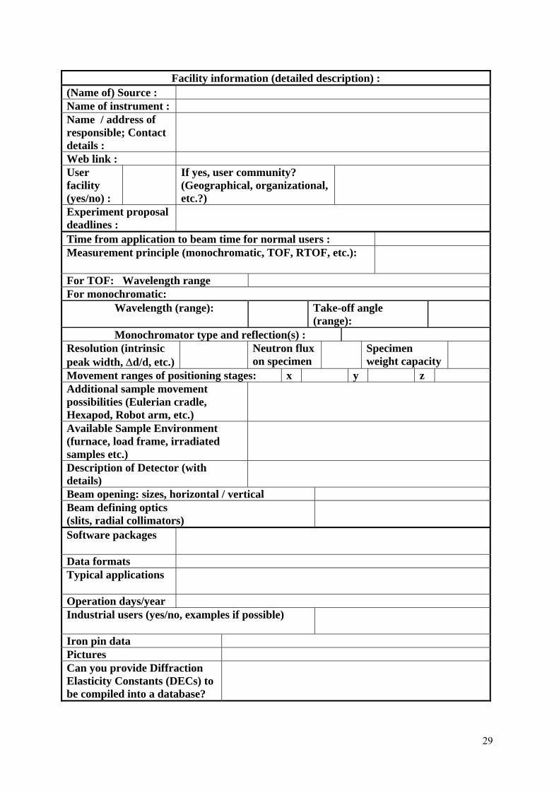
Facility information (detailed description) :
(Name of) Source : Name of instrument : Name / address of responsible; Contact details :
Web link : User facility (yes/no) :
If yes, user community? (Geographical, organizational, etc.?)
Experiment proposal deadlines :
Time from application to beam time for normal users : Measurement principle (monochromatic, TOF, RTOF, etc.):
For TOF: Wavelength range For monochromatic: Wavelength (range): Take-off angle
(range):
Monochromator type and reflection(s) : Resolution (intrinsic peak width, ∆d/d, etc.)
Neutron flux on specimen
Specimen weight capacity
Movement ranges of positioning stages: x y z Additional sample movement possibilities (Eulerian cradle, Hexapod, Robot arm, etc.)
Available Sample Environment (furnace, load frame, irradiated samples etc.)
Description of Detector (with details)
Beam opening: sizes, horizontal / vertical Beam defining optics (slits, radial collimators)
Software packages
Data formats Typical applications
Operation days/year Industrial users (yes/no, examples if possible)
Iron pin data Pictures Can you provide Diffraction Elasticity Constants (DECs) to be compiled into a database?
29