4. energy performance assessment of heat exchangers
TRANSCRIPT

4. ENERGY PERFORMANCE ASSESSMENTOF HEAT EXCHANGERS
55Bureau of Energy Efficiency
4.1 Introduction
Heat exchangers are equipment that transfer heat from one medium to another. The properdesign, operation and maintenance of heat exchangers will make the process energy efficientand minimize energy losses. Heat exchanger performance can deteriorate with time, offdesign operations and other interferences such as fouling, scaling etc. It is necessary toassess periodically the heat exchanger performance in order to maintain them at a high effi-ciency level. This section comprises certain proven techniques of monitoring the perfor-mance of heat exchangers, coolers and condensers from observed operating data of theequipment.
4.2 Purpose of the Performance Test
To determine the overall heat transfer coefficient for assessing the performance of the heatexchanger. Any deviation from the design heat transfer coefficient will indicate occurrence offouling.
4.3 Performance Terms and Definitions
Overall heat transfer coefficient, U
Heat exchanger performance is normally evaluated by the overall heat transfer coefficient Uthat is defined by the equation
When the hot and cold stream flows and inlet temperatures are constant, the heat transfercoefficient may be evaluated using the above formula. It may be observed that the heat pick upby the cold fluid starts reducing with time.

Nomenclature
A typical heat exchanger is shown in figure 4.1 with nomenclature.
4. Energy Performance Assessment Of Heat Exchangers
56Bureau of Energy Efficiency
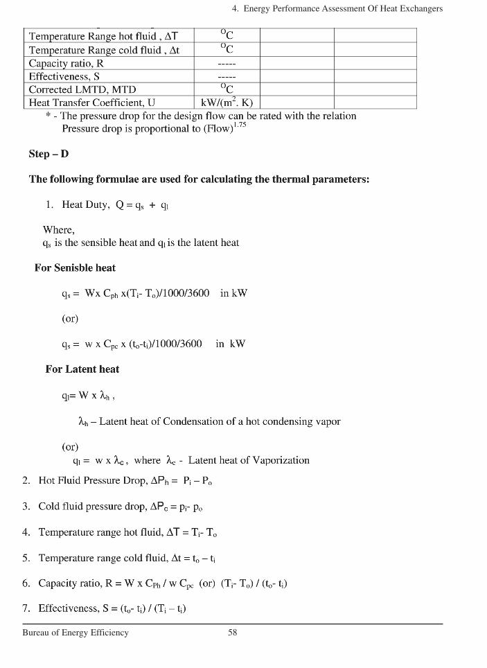
Heat duty of the exchanger can be calculated either on the hot side fluid or cold side fluidas given below.Heat Duty for Hot fluid, Qh = Wx Cph x (Ti–To) ………..Eqn–1, Heat Duty for Cold fluid, Qc = wx Cpc x ( to–ti) ………...Eqn–2 If the operating heat duty is less than design heat duty, it may be due to heat losses, fouling
in tubes, reduced flow rate (hot or cold) etc. Hence, for simple performance monitoring ofexchanger, efficiency may be considered as factor of performance irrespective of other para-meter. However, in industrial practice, fouling factor method is more predominantly used.
4.4 Methodology of Heat Exchanger Performance Assessment
4.4.1 Procedure for determination of Overall heat transfer Coefficient, U at field
This is a fairly rigorous method of monitoring the heat exchanger performance by calculatingthe overall heat transfer coefficient periodically. Technical records are to be maintained for allthe exchangers, so that problems associated with reduced efficiency and heat transfer can beidentified easily. The record should basically contain historical heat transfer coefficient dataversus time / date of observation. A plot of heat transfer coefficient versus time permits ratio-nal planning of an exchanger-cleaning program.
The heat transfer coefficient is calculated by the equation
U = Q / (A x LMTD)
Where Q is the heat duty, A is the heat transfer area of the exchanger and LMTD is tem-perature driving force.
The step by step procedure for determination of Overall heat transfer Coefficient aredescribed below
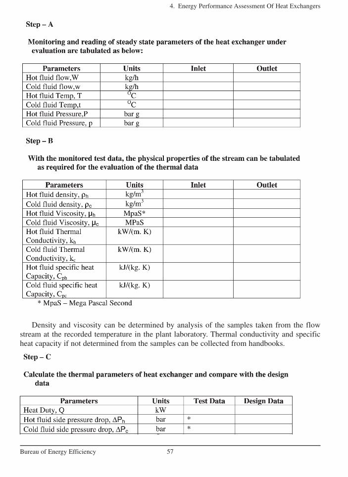
Density and viscosity can be determined by analysis of the samples taken from the flowstream at the recorded temperature in the plant laboratory. Thermal conductivity and specificheat capacity if not determined from the samples can be collected from handbooks.
4. Energy Performance Assessment Of Heat Exchangers
57Bureau of Energy Efficiency
4. Energy Performance Assessment Of Heat Exchangers
58Bureau of Energy Efficiency
4. Energy Performance Assessment Of Heat Exchangers
59Bureau of Energy Efficiency
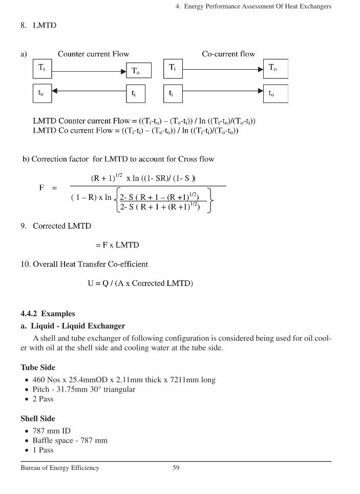
4.4.2 Examples
a. Liquid - Liquid Exchanger
A shell and tube exchanger of following configuration is considered being used for oil cool-er with oil at the shell side and cooling water at the tube side.
Tube Side
• 460 Nos x 25.4mmOD x 2.11mm thick x 7211mm long• Pitch - 31.75mm 30° triangular• 2 Pass
Shell Side
• 787 mm ID • Baffle space - 787 mm• 1 Pass

4. Energy Performance Assessment Of Heat Exchangers
60Bureau of Energy Efficiency

4. Energy Performance Assessment Of Heat Exchangers
61Bureau of Energy Efficiency
Heat Duty: Actual duty differences will be practically negligible as these duty differencescould be because of the specific heat capacity deviation with the temperature. Also, there couldbe some heat loss due to radiation from the hot shell side.
Pressure drop: Also, the pressure drop in the shell side of the hot fluid is reported normal(only slightly less than the design figure). This is attributed with the increased average bulktemperature of the hot side due to decreased performance of the exchanger.
Temperature range: As seen from the data the deviation in the temperature ranges could bedue to the increased fouling in the tubes (cold stream), since a higher pressure drop is noticed.
Heat Transfer coefficient: The estimated value has decreased due to increased fouling that hasresulted in minimized active area of heat transfer.
Physical properties: If available from the data or Lab analysis can be used for verificationwith the design data sheet as a cross check towards design considerations.
Troubleshooting: Fouled exchanger needs cleaning.
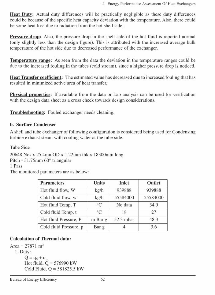
b. Surface Condenser
A shell and tube exchanger of following configuration is considered being used for Condensingturbine exhaust steam with cooling water at the tube side.
Tube Side
20648 Nos x 25.4mmOD x 1.22mm thk x 18300mm longPitch - 31.75mm 60° triangular1 PassThe monitored parameters are as below:
4. Energy Performance Assessment Of Heat Exchangers
62Bureau of Energy Efficiency
Parameters Units Inlet Outlet
Hot fluid flow, W kg/h 939888 939888
Cold fluid flow, w kg/h 55584000 55584000
Hot fluid Temp, T °C No data 34.9
Cold fluid Temp, t °C 18 27
Hot fluid Pressure, P m Bar g 52.3 mbar 48.3
Cold fluid Pressure, p Bar g 4 3.6
Calculation of Thermal data:
Area = 27871 m2
1. Duty:Q = qS + qL
Hot fluid, Q = 576990 kWCold Fluid, Q = 581825.5 kW
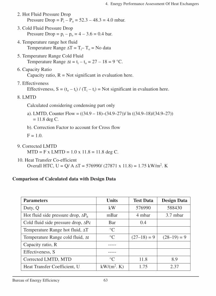
2. Hot Fluid Pressure DropPressure Drop = Pi – Po = 52.3 – 48.3 = 4.0 mbar.
3. Cold Fluid Pressure DropPressure Drop = pi – po = 4 – 3.6 = 0.4 bar.
4. Temperature range hot fluidTemperature Range ∆T = Ti– To = No data
5. Temperature Range Cold FluidTemperature Range ∆t = ti – to = 27 – 18 = 9 °C.
6. Capacity RatioCapacity ratio, R = Not significant in evaluation here.
7. EffectivenessEffectiveness, S = (to – ti) / (Ti – ti) = Not significant in evaluation here.
8. LMTD
Calculated considering condensing part only
a). LMTD, Counter Flow = ((34.9 – 18)–(34.9–27))/ ln ((34.9–18)/(34.9–27)) = 11.8 deg C.
b). Correction Factor to account for Cross flow
F = 1.0.
9. Corrected LMTDMTD = F x LMTD = 1.0 x 11.8 = 11.8 deg C.
10. Heat Transfer Co-efficientOverall HTC, U = Q/ A ∆T = 576990/ (27871 x 11.8) = 1.75 kW/m2. K
Comparison of Calculated data with Design Data
4. Energy Performance Assessment Of Heat Exchangers
63Bureau of Energy Efficiency
Parameters Units Test Data Design Data
Duty, Q kW 576990 588430
Hot fluid side pressure drop, ∆Ph mBar 4 mbar 3.7 mbar
Cold fluid side pressure drop, ∆Pc Bar 0.4
Temperature Range hot fluid, ∆T °C
Temperature Range cold fluid, ∆t °C (27–18) = 9 (28–19) = 9
Capacity ratio, R -----
Effectiveness, S -----
Corrected LMTD, MTD °C 11.8 8.9
Heat Transfer Coefficient, U kW/(m2. K) 1.75 2.37

Heat Duty: Actual duty differences will be practically negligible as these duty differencescould be because of the specific heat capacity deviation with the temperature. Also, there couldbe some heat loss due to radiation from the hot shell side.
Pressure drop: The condensing side operating pressure raised due to the backpressurecaused by the non-condensable. This has resulted in increased pressure drop across the steamside
Temperature range: With reference to cooling waterside there is no difference in the rangehowever, the terminal temperature differences has increased indicating lack of proper heattransfer.
Heat Transfer coefficient: Heat transfer coefficient has decreased due to increased amount ofnon-condensable with the steam.
Trouble shooting: Operations may be checked for tightness of the circuit and ensure proper venting of the system. The vacuum source might be verified for proper functioning.
C. Vaporizer
A shell and tube exchanger of following configuration is considered being used for vaporizingchlorine with steam at the shell side.
Tube Side
200 Nos x 25.4mmOD x 1.22mm thick x 6000mm longPitch - 31.75mm 30° triangular2 PassArea = 95.7.m2
4. Energy Performance Assessment Of Heat Exchangers
64Bureau of Energy Efficiency
Calculation of Thermal data:
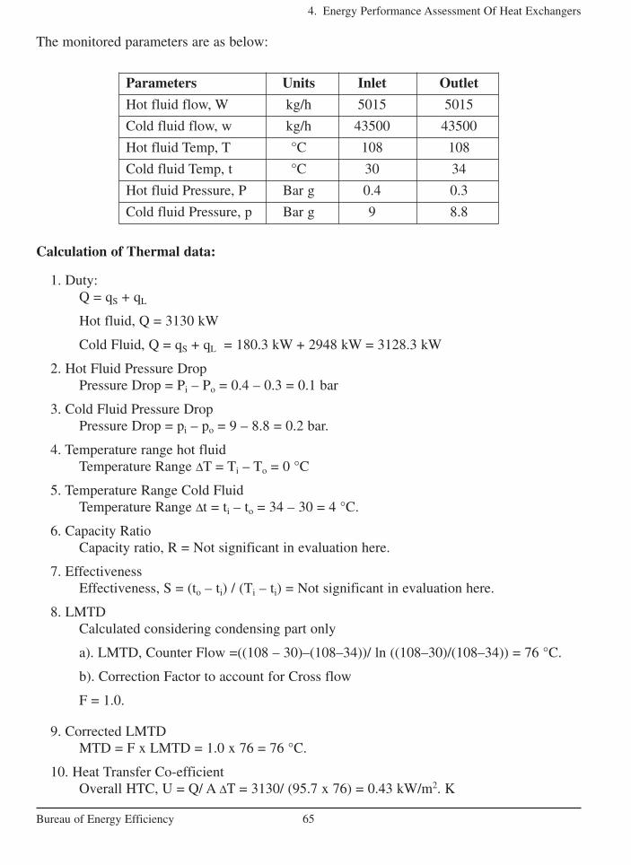
1. Duty:Q = qS + qL
Hot fluid, Q = 3130 kW
Cold Fluid, Q = qS + qL = 180.3 kW + 2948 kW = 3128.3 kW
2. Hot Fluid Pressure DropPressure Drop = Pi – Po = 0.4 – 0.3 = 0.1 bar
3. Cold Fluid Pressure DropPressure Drop = pi – po = 9 – 8.8 = 0.2 bar.
4. Temperature range hot fluidTemperature Range ∆T = Ti – To = 0 °C
5. Temperature Range Cold FluidTemperature Range ∆t = ti – to = 34 – 30 = 4 °C.
6. Capacity RatioCapacity ratio, R = Not significant in evaluation here.
7. EffectivenessEffectiveness, S = (to – ti) / (Ti – ti) = Not significant in evaluation here.
8. LMTDCalculated considering condensing part only
a). LMTD, Counter Flow =((108 – 30)–(108–34))/ ln ((108–30)/(108–34)) = 76 °C.
b). Correction Factor to account for Cross flow
F = 1.0.
9. Corrected LMTDMTD = F x LMTD = 1.0 x 76 = 76 °C.
10. Heat Transfer Co-efficientOverall HTC, U = Q/ A ∆T = 3130/ (95.7 x 76) = 0.43 kW/m2. K
4. Energy Performance Assessment Of Heat Exchangers
65Bureau of Energy Efficiency
Parameters Units Inlet Outlet
Hot fluid flow, W kg/h 5015 5015
Cold fluid flow, w kg/h 43500 43500
Hot fluid Temp, T °C 108 108
Cold fluid Temp, t °C 30 34
Hot fluid Pressure, P Bar g 0.4 0.3
Cold fluid Pressure, p Bar g 9 8.8
The monitored parameters are as below:

4. Energy Performance Assessment Of Heat Exchangers
66Bureau of Energy Efficiency
Parameters Units Test Data Design Data
Duty, Q kW 3130 3130
Hot fluid side pressure drop, ∆Ph Bar 0.1 Neg
Cold fluid side pressure drop, ∆Pc Bar 0.2
Temperature Range hot fluid, ∆T °C
Temperature Range cold fluid, ∆t °C 4 4
Capacity ratio, R -----
Effectiveness, S -----
Corrected LMTD, MTD °C 76
Heat Transfer Coefficient, U kW/(m2. K) 0.42 0.44
Comparison of Calculated data with Design Data
Heat Duty: There is no difference inferred from the duty as the exchanger is performing as perthe requirement
Pressure drop: The steam side pressure drop has increased in spite of condensation at thesteam side. Indication of non-condensable presence in steam side
Temperature range: No deviations
Heat Transfer coefficient: Even at no deviation in the temperature profile at the chlorine side,heat transfer coefficient has decreased with an indication of overpressure at the shell side. Thisindicates disturbances to the condensation of steam at the shell side. Non-condensable suspect-ed at steam side.
Trouble shooting: Operations may be checked for presence of chlorine at the shell sidethrough tube leakages. Observing the steam side vent could do this. Alternately condensate pHcould be tested for presence of acidity.
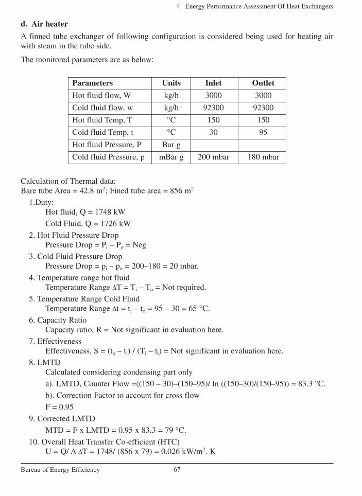
d. Air heater
A finned tube exchanger of following configuration is considered being used for heating airwith steam in the tube side.
The monitored parameters are as below:
4. Energy Performance Assessment Of Heat Exchangers
67Bureau of Energy Efficiency
Parameters Units Inlet Outlet
Hot fluid flow, W kg/h 3000 3000
Cold fluid flow, w kg/h 92300 92300
Hot fluid Temp, T °C 150 150
Cold fluid Temp, t °C 30 95
Hot fluid Pressure, P Bar g
Cold fluid Pressure, p mBar g 200 mbar 180 mbar
Calculation of Thermal data:Bare tube Area = 42.8 m2; Fined tube area = 856 m2
1.Duty:Hot fluid, Q = 1748 kW
Cold Fluid, Q = 1726 kW
2. Hot Fluid Pressure DropPressure Drop = Pi – Po = Neg
3. Cold Fluid Pressure DropPressure Drop = pi – po = 200–180 = 20 mbar.
4. Temperature range hot fluidTemperature Range ∆T = Ti – To = Not required.
5. Temperature Range Cold FluidTemperature Range ∆t = ti – to = 95 – 30 = 65 °C.
6. Capacity RatioCapacity ratio, R = Not significant in evaluation here.
7. EffectivenessEffectiveness, S = (to – ti) / (Ti – ti) = Not significant in evaluation here.
8. LMTDCalculated considering condensing part only
a). LMTD, Counter Flow =((150 – 30)–(150–95)/ ln ((150–30)/(150–95)) = 83.3 °C.
b). Correction Factor to account for cross flow
F = 0.95
9. Corrected LMTD
MTD = F x LMTD = 0.95 x 83.3 = 79 °C.
10. Overall Heat Transfer Co-efficient (HTC)U = Q/ A ∆T = 1748/ (856 x 79) = 0.026 kW/m22. K
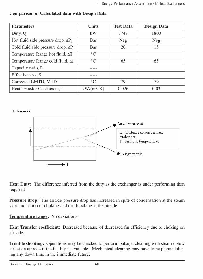
Comparison of Calculated data with Design Data
4. Energy Performance Assessment Of Heat Exchangers
68Bureau of Energy Efficiency
Parameters Units Test Data Design Data
Duty, Q kW 1748 1800
Hot fluid side pressure drop, ∆Ph Bar Neg Neg
Cold fluid side pressure drop, ∆Pc Bar 20 15
Temperature Range hot fluid, ∆T °C
Temperature Range cold fluid, ∆t °C 65 65
Capacity ratio, R -----
Effectiveness, S -----
Corrected LMTD, MTD °C 79 79
Heat Transfer Coefficient, U kW/(m2. K) 0.026 0.03
Heat Duty: The difference inferred from the duty as the exchanger is under performing thanrequired
Pressure drop: The airside pressure drop has increased in spite of condensation at the steamside. Indication of choking and dirt blocking at the airside.
Temperature range: No deviations
Heat Transfer coefficient: Decreased because of decreased fin efficiency due to choking onair side.
Trouble shooting: Operations may be checked to perform pulsejet cleaning with steam / blowair jet on air side if the facility is available. Mechanical cleaning may have to be planned dur-ing any down time in the immediate future.
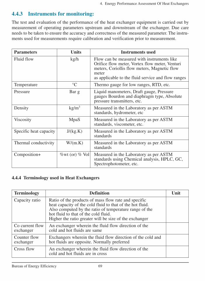
4.4.3 Instruments for monitoring:
The test and evaluation of the performance of the heat exchanger equipment is carried out bymeasurement of operating parameters upstream and downstream of the exchanger. Due careneeds to be taken to ensure the accuracy and correctness of the measured parameter. The instru-ments used for measurements require calibration and verification prior to measurement.
4. Energy Performance Assessment Of Heat Exchangers
69Bureau of Energy Efficiency
Parameters Units Instruments used
Fluid flow kg/h Flow can be measured with instruments like Orifice flow meter, Vortex flow meter, Venturi meters, Coriollis flow meters, Magnetic flowmeter as applicable to the fluid service and flow ranges
Temperature °C Thermo gauge for low ranges, RTD, etc.
Pressure Bar g Liquid manometers, Draft gauge, Pressure gauges Bourdon and diaphragm type, Absolute pressure transmitters, etc.
Density kg/m3 Measured in the Laboratory as per ASTM standards, hydrometer, etc
Viscosity MpaS Measured in the Laboratory as per ASTM standards, viscometer, etc.
Specific heat capacity J/(kg.K) Measured in the Laboratory as per ASTM standards
Thermal conductivity W/(m.K) Measured in the Laboratory as per ASTM standards
Composition+ %wt (or) % Vol Measured in the Laboratory as per ASTM standards using Chemical analysis, HPLC, GC, Spectrophotometer, etc.
Terminology Definition Unit
Capacity ratio Ratio of the products of mass flow rate and specific heat capacity of the cold fluid to that of the hot fluid. Also computed by the ratio of temperature range of the hot fluid to that of the cold fluid. Higher the ratio greater will be size of the exchanger
Co current flow An exchanger wherein the fluid flow direction of the exchanger cold and hot fluids are same
Counter flow Exchangers wherein the fluid flow direction of the cold and exchanger hot fluids are opposite. Normally preferred
Cross flow An exchanger wherein the fluid flow direction of the cold and hot fluids are in cross
4.4.4 Terminology used in Heat Exchangers

Density It is the mass per unit volume of a material kg/m3
Effectiveness Ratio of the cold fluid temperature range to that of the inlet temperature difference of the hot and cold fluid. Higher the ratio lesser will be requirement of heat transfer surface
Fouling The phenomenon of formation and development of scales and deposits over the heat transfer surface diminishing the heat flux. The process of fouling will get indicated by the increase in pressure drop
Fouling Factor The reciprocal of heat transfer coefficient of the dirt formed in the heat exchange process. Higher the factor lesser will be the overall heat transfer coefficient. (m2.K)/W
Heat Duty The capacity of the heat exchanger equipment expressed in terms of heat transfer rate, viz. magnitude of energy or heat transferred per time. It means the exchanger is capable of performing at this capacity in the given system W
Heat exchanger Refers to the nomenclature of equipment designed and constructed to transmit heat content (enthalpy or energy) of a comparatively high temperature hot fluid to a lower temperature cold fluid wherein the temperature of the hot fluid decreases (or remain constant in case of losing latent heat of condensation) and the temperature of the cold fluid increases (or remain constant in case of gaining latent heat of vaporisation). A heat exchanger will normally provide indirect contact heating. E.g. Acooling tower cannot be called a heat exchanger where water is cooled by direct contact with air
Heat Flux The rate of heat transfer per unit surface of a heat exchanger W/ m2
Heat transfer The process of transport of heat energy from a hot source to the comparatively cold surrounding
Heat transfer Refers to the surface area of the heat exchanger that surface or heat provides the indirect contact between the hot and cold Transfer area fluid in effecting the heat transfer. Thus the heat transfer
area is defined as the surface having both sides wetted with one side by the hot fluid and the other side by the cold fluid providing indirect contact for heat transfer m2
Individual The heat flux per unit temperature difference across Heat transfer boundary layer of the hot / cold fluid film formed Coefficient at the heat transfer surface. The magnitude of heat
transfer coefficient indicates the ability of heat conductivity of the given fluid. It increases with increase in density, velocity, specific heat, geometry of the film forming surface W/( m2.K)
4. Energy Performance Assessment Of Heat Exchangers
70Bureau of Energy Efficiency
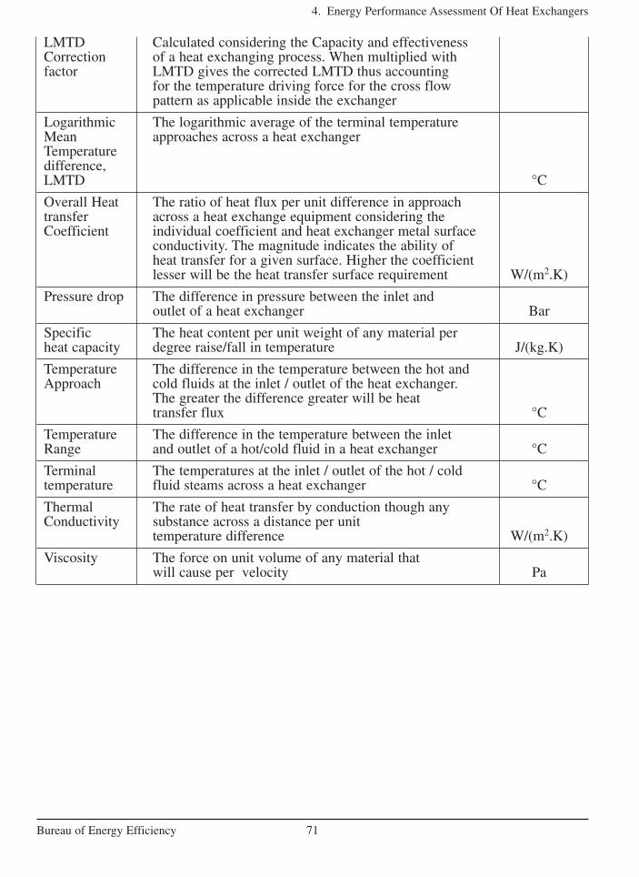
LMTD Calculated considering the Capacity and effectiveness Correction of a heat exchanging process. When multiplied with factor LMTD gives the corrected LMTD thus accounting
for the temperature driving force for the cross flow pattern as applicable inside the exchanger
Logarithmic The logarithmic average of the terminal temperature Mean approaches across a heat exchangerTemperature difference, LMTD °C
Overall Heat The ratio of heat flux per unit difference in approach transfer across a heat exchange equipment considering the Coefficient individual coefficient and heat exchanger metal surface
conductivity. The magnitude indicates the ability of heat transfer for a given surface. Higher the coefficient lesser will be the heat transfer surface requirement W/(m2.K)
Pressure drop The difference in pressure between the inlet and outlet of a heat exchanger Bar
Specific The heat content per unit weight of any material per heat capacity degree raise/fall in temperature J/(kg.K)
Temperature The difference in the temperature between the hot and Approach cold fluids at the inlet / outlet of the heat exchanger.
The greater the difference greater will be heat transfer flux °C
Temperature The difference in the temperature between the inlet Range and outlet of a hot/cold fluid in a heat exchanger °C
Terminal The temperatures at the inlet / outlet of the hot / cold temperature fluid steams across a heat exchanger °C
Thermal The rate of heat transfer by conduction though any Conductivity substance across a distance per unit
temperature difference W/(m2.K)
Viscosity The force on unit volume of any material that will cause per velocity Pa
4. Energy Performance Assessment Of Heat Exchangers
71Bureau of Energy Efficiency
4. Energy Performance Assessment Of Heat Exchangers
72Bureau of Energy Efficiency
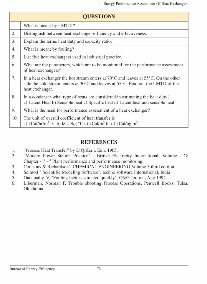
QUESTIONS
1. What is meant by LMTD ?
2. Distinguish between heat exchanger efficiency and effectiveness.
3. Explain the terms heat duty and capacity ratio.
4. What is meant by fouling?
5. List five heat exchangers used in industrial practice.
6. What are the parameters, which are to be monitored for the performance assessmentof heat exchangers?
7. In a heat exchanger the hot stream enters at 70°C and leaves at 55°C. On the otherside the cold stream enters at 30°C and leaves at 55°C. Find out the LMTD of theheat exchanger.
8. In a condenser what type of heats are considered in estimating the heat duty?a) Latent Heat b) Sensible heat c) Specific heat d) Latent heat and sensible heat
9. What is the need for performance assessment of a heat exchanger?
10. The unit of overall coefficient of heat transfer is a) kCal/hr/m2 °C b) kCal/kg °C c) kCal/m2 hr d) kCal/hg m2
REFERENCES1. "Process Heat Transfer" by D.Q.Kern, Edn. 1965.2. "Modern Power Station Practice" - British Electricity International- Volume - G;
Chapter - 7 - " Plant performance and performance monitoring.3. Coulsons & Richardson's CHEMICAL ENGINEERING Volume 3 third edition4. Scimod " Scientific Modeling Software", techno software International, India5. Ganapathy. V, "Fouling factor estimated quickly", O&G Journal, Aug 1992.6. Liberman, Norman P, Trouble shooting Process Operations, Penwell Books, Tulsa,
Oklahoma