4 iterative design development - transport scotland dualling programme: pitlochry to killiecrankie...
TRANSCRIPT
A9 Dualling Programme: Pitlochry to Killiecrankie
DMRB Stage 3 Environmental Statement
Chapter 4: Iterative Design Development
Page 1 of Chapter 4
4 Iterative Design Development
4.1 Introduction
4.1.1 The DMRB Stage 3 design of the proposed scheme as assessed and reported in this ES is the resultof approximately 12 months of design development to the preferred route option that was identified atDMRB Stage 2 (refer to Chapter 3: Consideration of Alternatives).
4.1.2 Environmental considerations have influenced the design, with knowledge of these gained through theEIA process, and from the environmental and engineering teams, consultees, and Transport Scotland.Through this process, the design has been iteratively updated and improved to reach the final DMRBStage 3 design.
4.1.3 The DMRB Stage 3 is a vital part of the EIA process for major roads infrastructure, as it presents anopportunity to avoid or mitigate potential effects through changes to aspects such as road alignment,land requirements, or the type and form of major structures. Changes incorporated into the DMRBStage 3 design during the design process that have ‘already’ avoided or reduced potentialenvironmental impacts are often referred to as embedded mitigation.
4.1.4 The potential impacts and proposed mitigation as reported in this ES are those identified followingassessment of the final DMRB Stage 3 design of the proposed scheme. As such, the potential effectsof earlier scheme design iterations are not described in the EIA chapters. This chapter (Chapter 4)therefore provides an overview of the iterative design process, and sets out the key environmentalconstraints and considerations that informed the final DMRB Stage 3 design.
4.2 Iterative Design Process
Constraints Review
4.2.1 One of the key project tools used to consider environmental constraints was the Jacobs GIS-basedProjectMapper®. All relevant environmental datasets, including those provided by statutory consulteesand other environmental bodies (refer to Chapter 7: Consultation and Scoping) and those gatheredthrough desk-based research and field surveys, were loaded onto an interactive database as ‘layers’.Each environmental GIS dataset layer can be switched on or off to show its extents in relation to theemerging proposed scheme design.
4.2.2 The ProjectMapper® tool was accessible to all those working on the project, enabling engineers toundertake preliminary sifting prior to review and input by the environmental team (e.g. locatingSustainable Drainage Systems (SuDS) outside of designated sites). The datasets were usedextensively through the design process to enable quick identification of potential issues to informdesign development. Photograph 4.1 provides an example of how the proposed scheme interacts withenvironmental constraints at specific locations using the datasets. Figure 5.1 provides an overview ofthe proposed scheme in context with the environmental constraints.
Design Assessment
4.2.3 As part of the design process, the engineering design is subject to constant development andrefinement. Examples of design refinement include revisions made to reflect landowner consultation,modelling or survey results (e.g. traffic movements, flood levels, geotechnical surveys), or addingfurther technical design detail.
4.2.4 To enable informed and timely input to the design, a programme of ‘interim design fixes’ was thereforeestablished. These snapshots of the draft design enabled all environmental specialists to review thesame proposals, and provide feedback to the engineers to inform the ongoing scheme development.
4.2.5 A total of three interim design fixes were issued, each having been informed by environmental,engineering/technical and consultation input.
4.2.6 Design fixes typically included refinements to:
A9 Dualling Programme: Pitlochry to Killiecrankie
DMRB Stage 3 Environmental Statement
Chapter 4: Iterative Design Development
Page 2 of Chapter 4
vertical alignment (i.e. altering the road height relative to existing ground).
horizontal alignment (i.e. altering the precise route of the road);
structures design (e.g. bridge design including pier locations, and culvert positioning);
routeing of access tracks, side roads and NMU provision;
positioning of drainage features and associated outfalls; and
gradients of earthworks slopes (embankments and cuttings).
Mitigation Workshops
4.2.7 Following assessment of each of the interim design fixes, a schedule of proposed design changes wasprepared by the environmental teams. The schedules typically included changes such asmodifications to road alignment, suggestions regarding siting of drainage features, proposals forgrading out of side slopes, or identification of environmentally sensitive areas to be avoided if possible.
4.2.8 Mitigation workshops were then held by the project team to enable the environmental specialists, EIACoordinators and engineering design teams to discuss proposals and influence the ongoing designdevelopment. These workshops were key to ensuring mitigation to avoid and minimise impacts wereincorporated into the proposed scheme design as further described in Section 4.3 (EmbeddedMitigation) of this chapter.
4.2.9 A specific example of the effectiveness of mitigation workshops combined with the use of theProjectMapper® tool is the lack of significant impacts in the cultural heritage assessment as reported inChapter 15 of this ES. For example, the design of the alignment and drainage north of the RiverTummel minimises impacts on a Scheduled Monument (Asset 271). Similarly, the access track toLittleton of Fonab and the junction at Foss Road at Balmore Cottages were designed to minimiseimpacts on Asset 775 and Asset 296, respectively. The design of the Faskally Crossing with wideningto the east of the existing structure minimises impacts on Asset 303, the existing aluminium footbridgeover Loch Faskally.
Stakeholder Input
4.2.10 As explained in Chapter 7 (Consultation and Scoping), the A9 Dualling Environmental Steering Group(ESG) meets on a monthly basis through DMRB Stages 2 and 3, covering all A9 dualling projects. Inaddition to input to environmental mitigation as described in the respective chapters of this ES,statutory consultees were able to advise and influence various aspects of the draft DMRB Stage 3design. The ESG is a valuable consultation forum but it is not a decision making or approvalmechanism. Statutory consultee input to draft designs for this project include, for example:
selection of a design for the new Tummel Crossing;
location of SuDS;
gradient of side slopes and earthworks along the route; and
landscape and ecology mitigation.
4.2.11 The Stage 3 design has also been informed by discussions with landowners and the owners ofaffected properties. These discussions have influenced the:
refinement of access arrangements to the properties at Littleton of Fonab, Middleton of Fonab,Overton of Fonab, Balmore Cottages, Kennels Cottage;
design of the Rob Roy Way Underpass;
design of the proposed landscape and ecology planting; and
location of SuDS in the vicinity of River Tummel and Loch Faskally.
A9 Dualling Programme: Pitlochry to Killiecrankie
DMRB Stage 3 Environmental Statement
Chapter 4: Iterative Design Development
Page 3 of Chapter 4
4.3 Embedded Mitigation
4.3.1 Some of the key design considerations during DMRB Stage 3 design development that avoided orreduced potential impacts are described further below.
Avoiding Loss of Designated Areas (River Tay SAC)
4.3.2 The River Tay SAC is designated as a Special Area of Conservation (SAC) under the EU HabitatsDirective, providing protection in relation to otter, Atlantic salmon and lamprey (sea, brook and river).
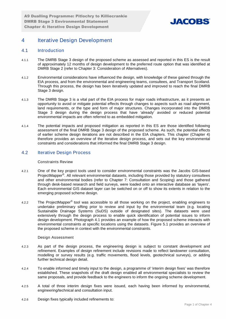
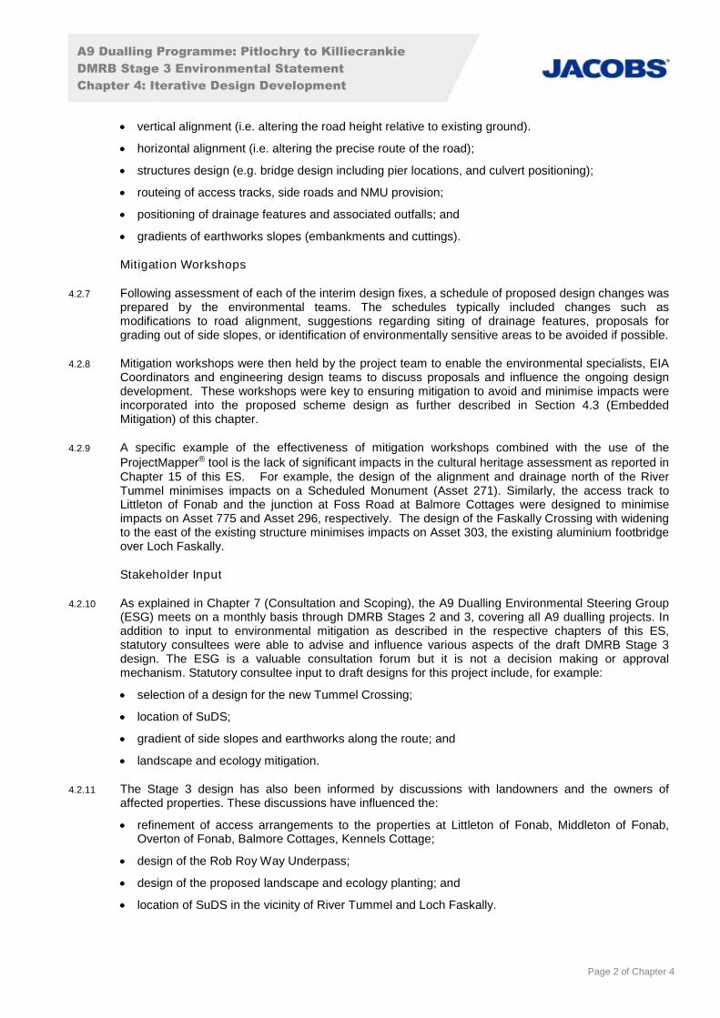
4.3.3 The existing A9 between Pitlochry and Killiecrankie crosses the River Tay SAC at two locations (RiverTummel at ch900 to ch1050 and Loch Faskally at ch4200 to ch4350) as shown in Photographs 4.1and 4.2.
Photograph 4.1: Aerial imagery and the River Tay SAC boundary at Pitlochry South Junction and Tummel Crossing
ProjectMapper®, 2017
River Tay SAC boundary
Existing A9
A9 Dualling Programme: Pitlochry to Killiecrankie
DMRB Stage 3 Environmental Statement
Chapter 4: Iterative Design Development
Page 4 of Chapter 4
Photograph 4.2: Aerial imagery and the River Tay SAC boundary at Pitlochry North Junction
ProjectMapper®, 2017
4.3.4 The River Tay SAC was identified as a key constraint during design development, with the aim ofavoiding or minimising the potential impacts of construction and operation such as habitat loss,changes to the watercourse, and water quality.
4.3.5 Examples of specific design changes that removed elements of the proposed scheme from the RiverTay SAC habitat were:
realignment of the access track at ch900 to minimise loss of River Tay SAC aquatic habitat; and
position of the outfalls at Pitlochry South Junction and around Loch Faskally.
Reducing Loss of Native and Ancient Woodland
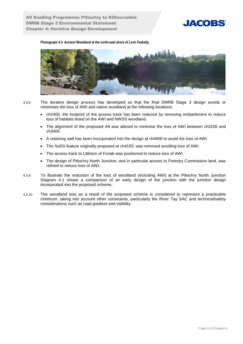
4.3.6 The existing A9 passes through extensive areas of woodland, some of which are identified in SNH’sAncient Woodland Inventory (AWI) and/or identified as native woodland through the Native WoodlandSurvey for Scotland. Woodland designated in the AWI is widespread across the study area, typicallybeing found along watercourses (such as the River Tummel and Loch Faskally, as shown inPhotograph 4.3) as well as on hillsides such as Craigower. From Port-na-Craig Dam at the south-eastern end of Loch Faskally to Faskally Caravan Park, the existing A9 passes through ancientwoodland designated as long-established of plantation origin.
4.3.7 In addition to AWI, woodland identified in the Forestry Commission’s Native Woodland Survey ofScotland (NWSS) is also widespread within the study area and along parts of the existing A9 corridor,overlapping in a number of areas with AWI woodland close to the A9, including around Littleton ofFonab, Pitlochry Estate and Craiglunie.
Existing A9
River Tay SAC boundary
A9 Dualling Programme: Pitlochry to Killiecrankie
DMRB Stage 3 Environmental Statement
Chapter 4: Iterative Design Development
Page 5 of Chapter 4
Photograph 4.3: Ancient Woodland at the north-east shore of Loch Faskally.
4.3.8 The iterative design process has developed so that the final DMRB Stage 3 design avoids orminimises the loss of AWI and native woodland at the following locations:
ch2400, the footprint of the access track has been reduced by removing embankment to reduceloss of habitats listed on the AWI and NWSS woodland.
The alignment of the proposed A9 was altered to minimise the loss of AWI between ch3100 andch3400.
A retaining wall has been incorporated into the design at ch4000 to avoid the loss of AWI.
The SuDS feature originally proposed at ch4150, was removed avoiding loss of AWI.
The access track to Littleton of Fonab was positioned to reduce loss of AWI.
The design of Pitlochry North Junction, and in particular access to Forestry Commission land, wasrefined to reduce loss of AWI.
4.3.9 To illustrate the reduction of the loss of woodland (including AWI) at the Pitlochry North JunctionDiagram 4.1 shows a comparison of an early design of the junction with the junction designincorporated into the proposed scheme.
4.3.10 The woodland loss as a result of the proposed scheme is considered to represent a practicableminimum, taking into account other constraints, particularly the River Tay SAC and technical/safetyconsiderations such as road gradient and visibility.

A9 Dualling Programme: Pitlochry to Killiecrankie
DMRB Stage 3 Environmental Statement
Chapter 4: Iterative Design Development
Page 6 of Chapter 4
Diagram 4.1: Pitlochry North Junction Comparative Design Iterations
Bridge Design to Reduce Ecological and Landscape Effects (Tummel Crossing)
4.3.11 The A9 currently crosses the River Tummel (part of the River Tay SAC) via the existing bridge atch900 to ch1050, where the river is approximately 80m wide bank to bank. Carriageway widening,required to provide the dual carriageway, necessitates construction of a new bridge for northboundtraffic which will be located adjacent to the existing structure.
4.3.12 The key environmental issues associated with the new bridge are potential implications on the RiverTay SAC, loss of flood plain and the landscape/visual impacts of the new structure. Other issues relategenerally to the footprint of the bridge options, with potential consequent implications on aspects suchas land-take and flood risk.
4.3.13 The A9 Dualling Strategic Environmental Assessment (SEA) (Transport Scotland, 2013) established aprinciple of avoiding construction within watercourses where possible and as such, a number of designoptions were considered for the Tummel Crossing. If a clear span bridge is provided (i.e. no piers inthe watercourse), matching the existing Tummel Underbridge in form the bridge structure would belonger and vertical alignment higher than the existing with a deeper deck structure. Conversely, a newbridge option with piers in the watercourse could be designed to closely resemble the existing bridge,which would result in a better landscape fit and lower visual impacts.
4.3.14 Given the above challenges in terms of engineering, economic and conflicting environmental factors,two additional options were considered. The first option provided a new clear span bowstring arch
A9 Dualling Programme: Pitlochry to Killiecrankie
DMRB Stage 3 Environmental Statement
Chapter 4: Iterative Design Development
Page 7 of Chapter 4
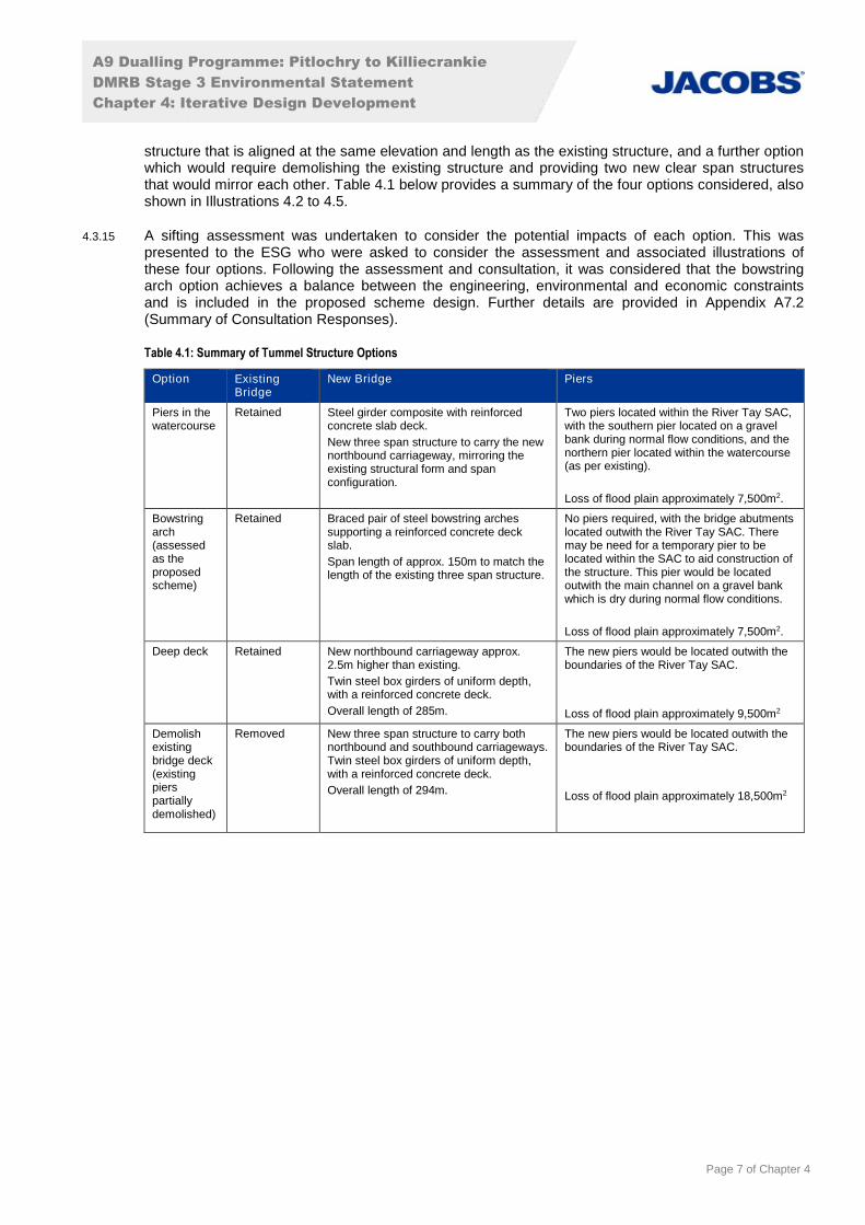
structure that is aligned at the same elevation and length as the existing structure, and a further optionwhich would require demolishing the existing structure and providing two new clear span structuresthat would mirror each other. Table 4.1 below provides a summary of the four options considered, alsoshown in Illustrations 4.2 to 4.5.
4.3.15 A sifting assessment was undertaken to consider the potential impacts of each option. This waspresented to the ESG who were asked to consider the assessment and associated illustrations ofthese four options. Following the assessment and consultation, it was considered that the bowstringarch option achieves a balance between the engineering, environmental and economic constraintsand is included in the proposed scheme design. Further details are provided in Appendix A7.2(Summary of Consultation Responses).
Table 4.1: Summary of Tummel Structure Options
Option ExistingBridge
New Bridge Piers
Piers in thewatercourse
Retained Steel girder composite with reinforcedconcrete slab deck.
New three span structure to carry the newnorthbound carriageway, mirroring theexisting structural form and spanconfiguration.
Two piers located within the River Tay SAC,with the southern pier located on a gravelbank during normal flow conditions, and thenorthern pier located within the watercourse(as per existing).
Loss of flood plain approximately 7,500m2.
Bowstringarch(assessedas theproposedscheme)
Retained Braced pair of steel bowstring archessupporting a reinforced concrete deckslab.
Span length of approx. 150m to match thelength of the existing three span structure.
No piers required, with the bridge abutmentslocated outwith the River Tay SAC. Theremay be need for a temporary pier to belocated within the SAC to aid construction ofthe structure. This pier would be locatedoutwith the main channel on a gravel bankwhich is dry during normal flow conditions.
Loss of flood plain approximately 7,500m2.
Deep deck Retained New northbound carriageway approx.2.5m higher than existing.
Twin steel box girders of uniform depth,with a reinforced concrete deck.
Overall length of 285m.
The new piers would be located outwith theboundaries of the River Tay SAC.
Loss of flood plain approximately 9,500m2
Demolishexistingbridge deck(existingpierspartiallydemolished)
Removed New three span structure to carry bothnorthbound and southbound carriageways.Twin steel box girders of uniform depth,with a reinforced concrete deck.
Overall length of 294m.
The new piers would be located outwith theboundaries of the River Tay SAC.
Loss of flood plain approximately 18,500m2
A9 Dualling Programme: Pitlochry to Killiecrankie
DMRB Stage 3 Environmental Statement
Chapter 4: Iterative Design Development
Page 8 of Chapter 4
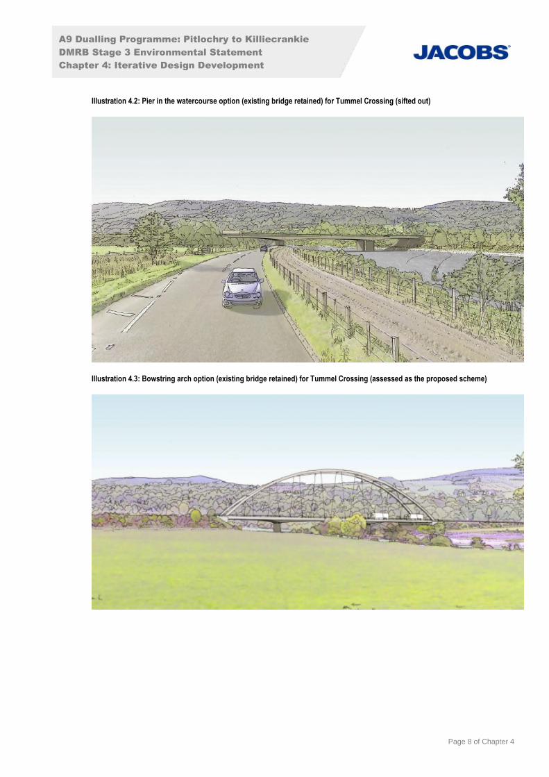
Illustration 4.2: Pier in the watercourse option (existing bridge retained) for Tummel Crossing (sifted out)
Illustration 4.3: Bowstring arch option (existing bridge retained) for Tummel Crossing (assessed as the proposed scheme)
A9 Dualling Programme: Pitlochry to Killiecrankie
DMRB Stage 3 Environmental Statement
Chapter 4: Iterative Design Development
Page 9 of Chapter 4
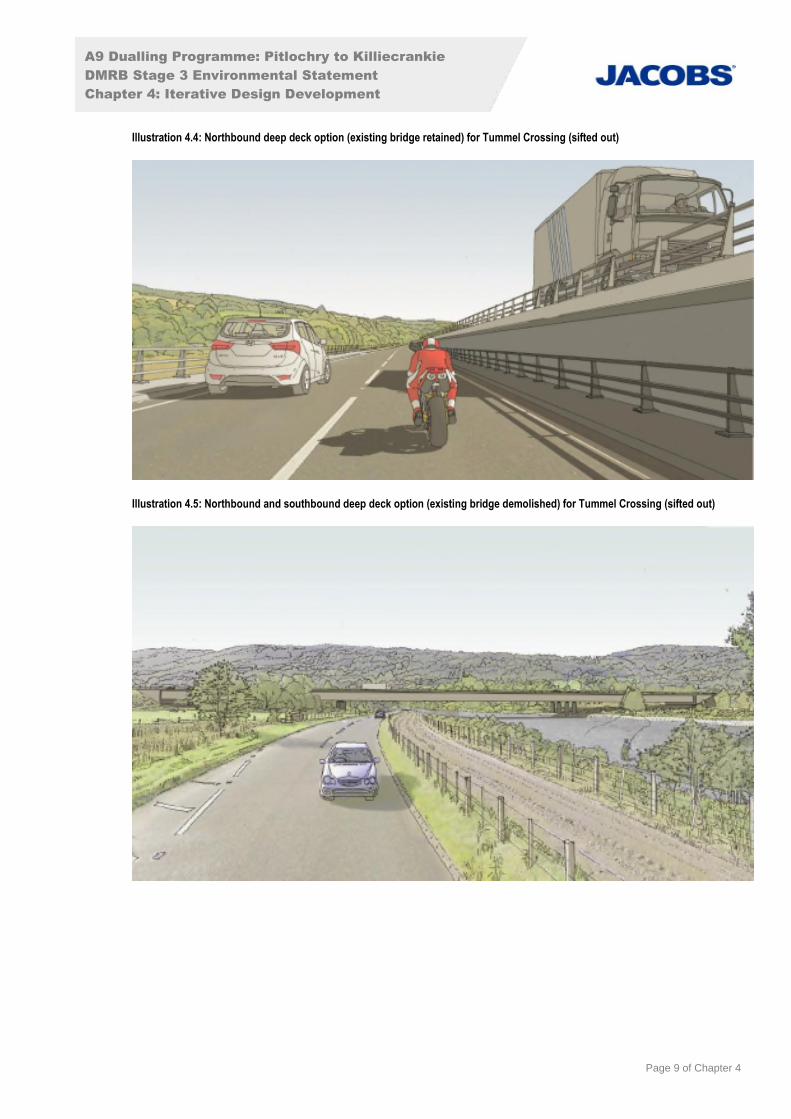
Illustration 4.4: Northbound deep deck option (existing bridge retained) for Tummel Crossing (sifted out)
Illustration 4.5: Northbound and southbound deep deck option (existing bridge demolished) for Tummel Crossing (sifted out)
A9 Dualling Programme: Pitlochry to Killiecrankie
DMRB Stage 3 Environmental Statement
Chapter 4: Iterative Design Development
Page 10 of Chapter 4
Avoiding Building Demolition
4.3.16 As part of the development of the proposed scheme during the DMRB Stage 2 design, a number ofoptions were developed for connecting C452 Clunie-Foss Road to the proposed A9, one of whichrequired the demolition of the Gate House (ch3900). The preferred option, which avoided thisdemolition, has been carried through to the final DMRB Stage 3 design.
Drainage Design – Constrained Sites
4.3.17 During the design development from the drainage design proposed at DMRB Stage 2 to DMRB Stage3, various issues were identified which effect the type and location of proposed SuDS components,resulting in a departure from the preferred provision of conventional SuDS at some locations.Constraints have included existing transport infrastructure, steep topography, loss of AncientWoodland, and increased flood risk. Four constrained drainage catchments were identified during theiterative drainage design process:
Drainage Catchment A - conventional SuDS were not possible due to the extended Dalshian RailUnderbridge, Highland Main Line railway and both the 3.33% AEP (30-year) and 0.5% AEP (200-year) flood extents of the River Tummel.
Drainage Catchment D - to move the SuDS retention pond further from the River Tummel (tominimise impact on the River Tummel, see below section), the drainage catchment had to be sub-divided in two (D1 and D2) and a 350m length of carriageway (Drainage Catchment D1) could notbe drained via conventional SuDS.
Drainage Catchments E and F - providing a SuDS detention basin or SuDS retention pond atch4200 and ch4450 would require the loss of a substantial area of woodland on the AWI due tothe steep topography and subsequent earthworks required.
4.3.18 To provide water quality treatment for these drainage catchments, filter drains are proposed incombination with a hydrodynamic vortex separator (HVS) (a proprietary system). The use ofproprietary systems in these constrained circumstances has been discussed with SEPA.
Drainage Design - Minimising Impacts on Watercourses
4.3.19 Various iterations have been made to the DMRB Stage 3 drainage to avoid or reduce potential waterquality and geomorphology impacts on watercourses. These include moving SuDS features away fromwatercourses to reduce the risk of sediment and pollutants entering watercourses during construction,moving outfall locations to areas of faster flowing water to maximise the rate of dispersal of treatedwater, and separating outfalls into the same watercourse to minimise the concentration of treatedwater entering watercourses. Specific examples include:
A SuDS feature originally proposed at ch50 was removed to avoid loss of floodplain capacity.
Outfall at ch900 moved downstream of Tummel Crossing from its previous location 65m upstreamto avoid impacts on a site where erosion is currently occurring at the bank and where existing bankreinforcement has become undermined. The outfall of the SuDS basin has also been set back fromthe bank to avoid direct modification to the bank and therefore reduce potential geomorphologicalimpacts.
SuDS pond (as discussed in paragraph 4.3.17) at ch1100 was originally located within the 10-yearfloodplain and therefore was susceptible to flooding which would have resulted in mobilisation ofpollutants and discharge into River Tummel. This SuDS pond has been moved approximately200m back from previous location and the outfall from this pond moved to a minor watercoursewhich outfalls to the River Tummel.
Outfall from SuDS feature at ch4600 moved from discharging upstream of Clunie Footbridge todownstream of Clunie Underbridge avoiding additional disturbance to habitats and visual impacts inan area otherwise directly unaffected by the works.
A9 Dualling Programme: Pitlochry to Killiecrankie
DMRB Stage 3 Environmental Statement
Chapter 4: Iterative Design Development
Page 11 of Chapter 4
Drainage Design - SuDS: Detention Basin Vs Retention Pond
4.3.20 The proposed scheme includes five SuDS retention ponds to attenuate runoff from the dualcarriageway, via filter drains. The SuDS is designed to treat road runoff pollutants to acceptable levelsbefore it enters watercourses. The construction and footprint of the SuDS features are included as partof the DMRB Stage 3 design of the proposed scheme as an embedded measure to mitigate potentialwater quality impacts.
4.3.21 During design development, engineering and environmental factors were considered to confirm thedesign of each SuDS feature, including whether attenuation should be achieved by a dry detentionbasin or by a wet retention pond. The decision was based on guidance in the Construction IndustryResearch and Information Association (CIRIA) SuDS Manual (2015), which sets out the four pillars ofSuDS design which are water quantity, water quality, amenity and biodiversity. As such, the followingwere considered:
Highways Agency Water Risk Assessment Tool (HAWRAT) assessment which shows theattenuation levels of a retention pond are typically higher than a detention basin;
size and topography of the catchment area;
potential issues with seepage into the structural embankment;
integrating the SuDS feature within the surrounding landscape character and topography;
potential to contribute to visual amenity; and
potential to contribute to biodiversity including areas of potential habitat for northern damselfly.
4.3.22 Table 11.19 (Chapter 11: Road Drainage and the Water Environment) provides the outcomes of theprocess, while further details of the SuDS design principles to be adopted as part of the detaileddesign and construction of the proposed scheme are set out in Appendix A13.7 (SuDS DesignPrinciples).
Provisions for Non-Motorised Users
4.3.23 During the design development, the engineering and environmental team worked to fully consider,maintain and where possible enhance NMU routes affected by the proposed scheme. Embeddedmitigation that emerged from this process includes:
new underpass providing a safe crossing point of the A9 for users of the Rob Roy Way;
NMU route realignments (refer to Table 4.2 and Figure 9.2); and
enhanced NMU connections to Tay Forest Park (Craigower) (shown on Figure 9.2f).
Table 4.2: NMU Route Realignments, as shown on Figure 9.2
Location (Path ref.) Description of Realignment Proposed
Path 69 Local path realigned along new access track with a type 1 compacted surface.
Path 72 (Rob Roy Way) NMUs rerouted via new underpass with appropriate signage provided and a paved surface
Path 76 Path realigned along new footway with a paved surface.
Path 76a Path realigned along new footway in road verge with a paved surface.
Path 95 NMUs accessing Tay Forest Park (Craigower) to be rerouted from A924 across new bridge, viastairs, with a paved surface, connecting into Path 96 which is unsurfaced.
4.4 Conclusions
4.4.1 The DMRB Stage 3 design of the proposed scheme is the result of an iterative design developmentprocess that avoids or reduces the potential for impacts on the surrounding environment. It hasdeveloped and improved the preferred route option that was identified at DMRB Stage 2 (refer toChapter 3: Alternatives Considered) to reach a design that is described in Chapter 5 (The ProposedScheme) and assessed as part of the DMRB Stage 3 EIA.

A9 Dualling Programme: Pitlochry to Killiecrankie
DMRB Stage 3 Environmental Statement
Chapter 4: Iterative Design Development
Page 12 of Chapter 4
4.5 References
Construction Industry Research and Information Association (2015). The SuDS Manual, CIRIA C753.
Transport Scotland (2013) A9 Dualling Programme Strategic Environmental Assessment (SEA) –Environmental Report