400 kw rf stations operational experience
TRANSCRIPT

FREIA Report 2019/06 November 2019
Department of Physics and Astronomy Uppsala University P.O. Box 516 SE – 751 20 Uppsala Sweden
Papers in the FREIA Report Series are published on internet in PDF format. Download from http://uu.diva-portal.org
DEPARTMENT OF PHYSICS AND ASTRONOMY UPPSALA UNIVERSITY
400 kW RF Stations Operational Experience
Overview of the operation experience during 2018-2019 with the Itelco-Electrosys and DB
Science stations at the FREIA Laboratory.
Roger Ruber, Rolf Wedberg, Tord Peterson, Dragos Dancila, Long Hoang Duc, Johan Eriksson
Uppsala University, Uppsala, Sweden

FREIA Report 2019/06
- 2 / 24 -
400 kW RF Stations Operational Experience R. Ruber, R. Wedberg, T. Peterson, D. Dancila, L.H. Duc, J. Eriksson
Uppsala University, Uppsala, Sweden
Abstract
We present the operational experience with the Itelco-Electrosys and DB Science 400 kW RF stations installed at the FREIA Laboratory. From the summer of 2018 to the summer of 2019 the stations were used for the test of the spoke cryomodule prototype for ESS. Unfortunately multiple issues with both RF stations delayed or inhibited normal operation. The Itelco-Electrosys station was out-of-operation from October 2018 to June 2019, due to multiple issues, which took a long time to understand and solve.

FREIA Report 2019/06
- 3 / 24 -
Table of Contents 1. Introduction ............................................................................................................................................................... 4
2. Tetrode Tubes and Cavities ..................................................................................................................................... 5 2.1. Tetrode TH595 ................................................................................................................................................ 5 2.2. Tetrode TH595A ............................................................................................................................................. 7 2.3. Cavity TH18595A ............................................................................................................................................ 7
3. Itelco-Electrosys RF Station Operational Experience ........................................................................................ 8 3.1. Arcing in HPA2 ............................................................................................................................................... 8 3.2. Pre-amplifier for HPA2 ............................................................................................................................... 11 3.3. Arcing in the Hybrid Coupler ..................................................................................................................... 12 3.4. Arcing in HPA1 ............................................................................................................................................ 13 3.5. Malfunction of HPA1 Tetrode ................................................................................................................... 14
4. DB Science RF Station Operational Experience ............................................................................................... 15 4.1. Interlock System ............................................................................................................................................ 15 4.2. CW Operation ............................................................................................................................................... 15 4.3. Crowbar Trips ............................................................................................................................................... 15 4.4. G2 Voltage ..................................................................................................................................................... 15
5. Vibrations during Construction House 9 ........................................................................................................... 17 5.1. Measurement Grid ........................................................................................................................................ 17 5.2. Measurement Summary ................................................................................................................................ 19
6. Discussion and Conclusions ................................................................................................................................. 20 6.1. Air Quality ...................................................................................................................................................... 20 6.2. Arcing ............................................................................................................................................................. 20 6.3. Tube Overheating ......................................................................................................................................... 22
7. Bibliography ............................................................................................................................................................ 24

FREIA Report 2019/06
- 4 / 24 -
1. Introduction Two 400 kW RF stations at 352 MHz are installed at the FREIA Laboratory. One manufactured by Itelco-Electrosys [1] was commissioned in 2015 and the other one was manufactured by DB Science and was commissioned in 2016 [2].
In June 2018 the construction started of Ångström House 9, a new building adjacent to the FREIA Laboratory. Ramming of metal walls for digging cellars and foundations caused excessive vibrations in the FREIA Laboratory building of over 5 mm/s and up to 10 mm/s. After notifying the construction responsible the work was halted and resumed with a limit set at 2.9 mm/s as the liquefier and cryostat equipment at FREIA start to resonate at vibrations above 3 mm/s.
The RF stations were not in operation from June to September 2018. When attempting to re-start the stations in October 2018 the Itelco-Electrosys station failed to operate properly. As a consequence, the Itelco-Electrosys station was out-of-operation from October 2018 to June 2019 due to multiple issues which took a long time to understand and solve.

FREIA Report 2019/06
- 5 / 24 -
2. Tetrode Tubes and Cavities Both RF stations are equipped with 2 tetrode vacuum tube amplifiers, each with an individual external cavity tuned to 352.21 MHz.
The RF station manufactured by Itelco-Electrosys was ordered with 4 tetrodes (of which 2 spare) and 3 cavities (of which 1 spare). The RF station manufactured by DB Science station was ordered with 2 tetrodes and 2 cavities (no spares).
As of today, four tetrodes are installed in the RF stations. These tubes of type TH595 and TH595A are manufactured by Thales AVS France. The two tube types are plug-compatible.
2.1. Tetrode TH595 The tubes of type TH595 [3] are rated in CW operation up to 30 kW up to 250 MHz or short pulse operation up to 200 kW peak power, up to 450 MHz. They are used in pulsed operation at 352 MHz, 3.5 ms pulse length, and 14 Hz repetition rate (ESS pulse length and repetition rate). Six tetrodes of the TH595 type have been delivered together with the RF stations. Three are broken and send back to Thales for inspection.
• SN 755305 - broken o Service time 579 hours. o Has short circuit cathode to G1,
this only appears in hot condition. o Sent to Thales for inspection beginning of April 2019. o Assessment report by Thales, e-mail dated 3-May-2019
We could hi-pot K to G1 up to 1.6 kV, but not up to 2.0 kV. Hi-pot on other electrodes is OK. Capacitances are regular. We raised filament voltage, and then waited for 15 minutes. Upon applying pulses of
accelerating voltage on the other electrodes (G1, G2, anode), it came out that voltage (even as low as 100 V) went down to zero immediately, as if there were a short, K to G1.
o Assessment report by Thales, e-mail dated 29-May-2019 For the time being, we confirmed the short-circuit, cathode to G1, in hot condition. We dismounted the water jacket. It does not bear any evidence of degradation. We opened the tetrode. It comes out that the grids and the cathode do not show
deformation. On the other hand, we were very surprised to discover metallic particles fallen in between cathode and control grid meshes. For the moment, we suspect tetrode internal overheating. We have to investigate further prior to come to more definite conclusion.
o Thales Failure Analysis Report, RMA No.: 60 086 796 [5]
Observed Defect:
• Tetrode insulation in cold condition is OK.
• Emission curves cannot be drawn, because as low voltage as 100 V on G1 is immediately shorted.
Inspection Result:

FREIA Report 2019/06
- 6 / 24 -
• Anode cooling jacket: sealing on anode flat top, O-ring water gasket, and RF wound wire ring are OK.
• Anode inner surface got blackened. Main insulator got darkened (see picture)
• Marks of severe arcs, G1 to G2, at the bottom of grid mesh. (see picture of G1)
• The upper (first) thermal/getter shield got deformed, which fostered electrical arc with G1 top inner surface
• The second thermal/getter shield got stuck with filament plate.
• Inside the heater cylindrical inner structure, the upper thermal shield got rolled in shape, and brittle.
• Cathode got deformed. Also, the tantalum belts, onto which cathode mesh ends are welded, got partly crushed into powder, resulting in snow crystal-shaped particles in-between cathode-to-G1 gap.
o
• SN 755307 – in service Electrosys HPA1 o service time 600 hours, o Sent to Thales for inspection
Reason high G2 current. The bias of is at the edge of tolerance. 239 V
o Returned by Thales, put back in use
• SN 753397 – in service Electrosys HPA2 o Service time 600 hours.
• SN 762034 – broken – at Thales o Broken during transport to Uppsala from DB Science o Sent to Thales for inspection
Inspection report??
• SN 761496 – broken – at Thales o Service time 3000 hours? o was in service in DB B section. o Short circuit cathode to control grid
The control grid voltage went down to 5 V with warm filament and when the filament cold off the voltage reached normal -300 to -200 V
o Sent to Thales for inspection o Thales Failure Analysis Report, RMA No.: 60 088 363 [6]
Observed Defect:
• Tetrode insulation in cold condition is OK.
• Short-circuit, K to G1, as soon as filament voltage is exceeding 2 V. Inspection Result:
• Anode cooling jacket: sealing on anode flat top, O-ring water gasket, and RF wound wire ring are OK.
• Anode inner surface got blackened. Main insulator got darkened (see picture)
• The upper (first) thermal/getter shield got deformed. The second one got partially stuck with filament plate.

FREIA Report 2019/06
- 7 / 24 -
• Filament plate deformed, resulting in cathode deformed, and cathode eventually in touch to G1 mesh.
• Marks of severe arcs, G1 to G2, at the bottom of grid mesh. (see picture of G1)
• Inside the heater cylindrical inner structure, the uppest thermal shield got rolled in shape, and brittle.
• SN 751465 – in service in DB A section o Service time 3000 hours?
2.2. Tetrode TH595A The tubes of type TH595A [4] are plug compatible with the TH595 while having an improved design of the grids to withstand a higher average power level. The TH595A delivers max. 210 kW peak power up to 360 MHz. Two tetrodes of the new TH595A type have been ordered of which one has been delivered in September 2019 and the other one is awaiting delivery.
• SN 901204 – in service in DB B section o Ordered 9-Apr-2019, expected delivery 26-Jul-2019 -> 30-Aug-2019 o Delivered 5-Sep-2019
• SN tbc – ordered o replacement under warranty by DB Science for SN 762034 o DB Science to order the tube on 25-Apr-2019, expected delivery end February 2020 o Re-ordered on 06-Nov-2019 by DB Science, expected delivery date not known
2.3. Cavity TH18595A All cavities are of type TH18595A designed for 352.21 MHz operation of the TH595 tetrode tubes. Four cavities of type are installed in the RF stations and one is spare.
• SN 753780 – spare o was in service in Electrosys HPA1 o grounding short through the screen grid
electric damage: insulation pipe in G2 capacitor o repaired at FREIA.
• SN 753781 – in service in Electrosys HPA2 • SN 776893 – in service in DB A section • SN 776892 – in service in DB B section • SN 753779 – in service in Electrosys HPA1

FREIA Report 2019/06
- 8 / 24 -
3. Itelco-Electrosys RF Station Operational Experience The Itelco-Electrosys station was out-of-operation from October 2018 to June 2019. The down time was partly caused by a faulty circuit in the very low power and control part. This station has analogue phase shifters and attenuators. These circuits are over complex for what the station is supposed to do. And thus, a failures in some small components brings down the whole station; a weakness of the Electrosys station.
3.1. Arcing in HPA2 In October 2018 arcing occurred in the tetrode amplifier module # 2 (HPA2). Only 50 kW peak power could be reached before the series switch opened. A ticking sound could be heard from HPA2. The lid of the tetrode cavity was opened, and with an endoscope camera, we observed grey coloured spots on one of the water hoses. See figure 3.1 below, showing the water hose from the cooling inlet (red) and the corona ring of the connector (light grey). Our interpretation is that some arcing took place round the water connection and therefore the plastic net around the hose turned grey. The silver coloured reflecting pieces in between the hose and corona ring also seem to result from arcing. Figure 3.2 shows the water hose from the cooling inlet and its corona ring after removal.
Figure 3.1: Visible colouring of the water hose in HPA2.

FREIA Report 2019/06
- 9 / 24 -
Figure 3.2: The water hose (left) and its corona ring (right) after removal.
After removal, the water hose was cut by 5 cm. It was reconnected, tested for water leakage after which the tetrode was reinstalled into the cavity. The tetrode filament was run for 20 hours after which a new trial was made with RF. A power output level of just below 100 kW was reached for the total output of the RF station before arcing started again.
The HV switch opens in HPA2. The interlock reason was that dV/dt is faster than the dI/dt and that triggered the crowbar. The anode current goes to approximately 50 A. We hear clicks from the tetrode amplifier when arcing occurs.
An engineer from Itelco-Electrosys (Antonio Frizzi) visited the FREIA Laboratory on 20-21 November 2018 to investigate the problem.
After more investigation it was found that the cavity has approximately 100 Ohm to ground in the G2 circuit.
The cavity was replaced with a spare cavity, after which the new cavity was tuned mechanically to the nominal operating frequency with the installed tetrode.
Possible arcing damage was found in the G2 connector of the removed cavity as shown in figure 3.3. The small tube that contains the banana connector for the G2 connection and the wire of that connector have both black stains. The disassembled tube and insulator are shown in figure 3.4.
Thales provided replacement parts to repair the cavity (figure 3.5).

FREIA Report 2019/06
- 10 / 24 -
Figure 3.3: Arcing damage in the G2 connector of the cavity
Figure 3.4: The damaged G2 tube and insulator

FREIA Report 2019/06
- 11 / 24 -
Figure 3.5: Replacement parts for the G2 connector
After repairing the cavity, Thales was informed of some errors in the drawing of the part showing the G2 connector. Thales promised to improve the drawings and to make them more user friendly.
After replacing the cavity, the tetrode in HPA2 was replaced. However we could not reach full power and the original tetrode was installed back into HPA2. Then HPA1 tripped on dV/dt when the total power output reached 70 kW.
The final cause of the problem is believed to be the tetrode in HPA1. It is as if the cathode sometimes made contact with the grid. Since the grid has higher output impedance than the cathode, the grid came to zero potential and current from anode to cathode became so high that it appeared like a short circuit in the path from anode to ground.
The original tetrode SN 755307 was shipped to Thales for testing.
Replaced by tetrode with SN 755305.
The cavity TH 18595A with SN 753780 was repaired by ourselves.
Replacement of the cavity with SN 753779.
3.2. Pre-amplifier for HPA2 The pre-amplifier module 3 for HPA2 gives low output RF power. An extensive investigation shows that the "driver" and "final" amplifier modules are working correctly and therefore the problems must be located in the RF input control. The PA (AH101 transistor), right before the input to the pre-driver stage, was broken.
Itelco-Electrosys ships (for free) a new part: AH101 RF-amplifier.
Next another part in the RF control is malfunctioned: analogue switch ADG901BRM.
Itelco-Electrosys ships a new part. Since then the pre-amplifier works correctly.

FREIA Report 2019/06
- 12 / 24 -
Figure 3.6: The low power controls part.
3.3. Arcing in the Hybrid Coupler We continued trimming the RF station and reached over 100 kW. There is still a phase unbalance but the amplitude unbalance has been reduced to 0.6 dB. The gain of the module 3 of HPA2 is too high in comparison with the other 2 modules (it delivers 1000 W v.s. 500 W, for similar input power). We run some test with the RF station connecting the USB interface to the driver module 3 and changing the gain parameters (reduction by 3 dB of the gain of module 3). As a result, the drivers are now delivering power much more evenly and the two tetrodes have a similar output power. After more tuning we managed to compensate the phase and amplitude unbalance.
FREIA Report 2019/06
- 13 / 24 -
However HPA1 gives a dV/dt alarm.
We suspect RF arcing in the output circuit.
First we checked the static load that is connected to the output of the RF Station. Then we checked the output load of the hybrid combiner. Finally we opened the coax lines on the top of the station running from the tetrode amplifier output to the input of the hybrid combiner. Here we discovered metallic dust which probably was present from the factory assembly and had moved due to the vibrations during the construction work of House 9 next to FREIA.
However HPA1 gives a dV/dt alarm.
We do a high voltage insulation test on HPA1 with 20 kV DC which does not show any failures.
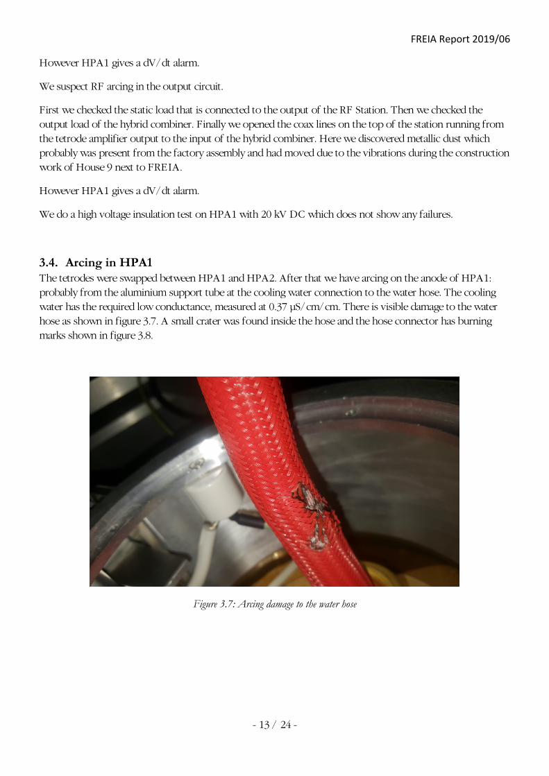
3.4. Arcing in HPA1 The tetrodes were swapped between HPA1 and HPA2. After that we have arcing on the anode of HPA1: probably from the aluminium support tube at the cooling water connection to the water hose. The cooling water has the required low conductance, measured at 0.37 µS/cm/cm. There is visible damage to the water hose as shown in figure 3.7. A small crater was found inside the hose and the hose connector has burning marks shown in figure 3.8.
Figure 3.7: Arcing damage to the water hose

FREIA Report 2019/06
- 14 / 24 -
Figure 3.8: Arcing damage at the inside of the hose and the connector
3.5. Malfunction of HPA1 Tetrode The tetrode in HPA1 seems to be malfunctioning.
With filament current on, after a while the control grid power supply is switched on. We have then –70 mA in control grid current at -270 V. The anode voltage switches are leaking app. 2.5 mA which usually gives 10 kV in anode voltage when screen grid power supply is off. During the failure, the anode voltage was 0 kV. The tetrode seems to be conducting in spite of the negative voltage of -270 V applied on the control grid.
Tetrode SN 755305 is dismounted and shipped to Thales for inspection. After inspection, Thales declared it broken. It is replaced by the tetrode with SN 753397.

FREIA Report 2019/06
- 15 / 24 -
4. DB Science RF Station Operational Experience The DB Science station has been in operation for the majority of time but has/had a few minor issues.
4.1. Interlock System It took some time to understand how the safety interlock system works due to incomplete documentation. The whole interlock is one single chain.
When the interlock has been triggered it is not possible to switch on the filament heater power supply. However, the filament heater power supply will remain on if it was on when the interlock is triggered.
4.2. CW Operation CW operation is limited to 10 kW + 10 kW with TH595A type tetrode tubes.
4.3. Crowbar Trips From time to time the crowbar interlock triggers and switches off the station during operation. The cause has not yet been determined with full confidence.
Possible causes are:
1. Crowbar triggered due to arcing in the cavity around the water hose connection. It has been observed that the crowbar triggered when anode voltage was applied, without RF on!
2. Invisible sharp peak in the output RF causing arcing, when we lock the cavity at 12 MV/m. The maximum power required during the filling time was regulated by the PI-loop, and always requires 370 kW maximum.
3. Most common reason is when the Cathode touches the Grid. The Grid voltage will then be 0-8 V and the Tetrode will conduct very high anode current. In the Electrosys RF station, the interlock and series switch in would open. In the DB station, the crowbar will fire which makes it looks like a short circuit to ground at the anode.
4.4. G2 Voltage During RF conditioning of the power couplers the DB station failed with the error "Absent VG2" in section A on Saturday 18-Aug-2019. It appeared that the G2 voltage is unstable.
An investigation of the cause is still ongoing.
The tube in section DB-B fails (SN 761496) and is replaced by a new tube of type TH595A (SN 901204).
The ripple observed on the G2 voltage is in the order of 150 V as shown in figure 4.1.

FREIA Report 2019/06
- 16 / 24 -
Figure 4.1: Ripple on the G2 voltage

FREIA Report 2019/06
- 17 / 24 -
5. Vibrations during Construction House 9 The construction work for the extension of the Ångström Laboratory started in March 2018. This includes a new building called House 9 (Hus 9 in Swedish) next to the FREIA Laboratory building (referred to as House 30 or FREIALAB). Ramming of metal walls for the construction of the cellars of House 9 started in June 2018. During the works, the read-out of several vibration monitors installed in the area where monitored automatically and reported in writing monthly [7].
Figure 5.1: Location of vibration sensors.
5.1. Measurement Grid Figure 5.1 shows the area layout of the Ångström Laboratory and the location of vibration sensors during the ramming works [7]. Sensors Mp06V and Mp06Ö are located inside the FREIA Laboratory building at the west and east sides respectively. These sensors were only measuring in vertical direction. Another sensor, Mp01VLT, located in the clean room facilities was measuring in 3 directions: vertical, longitudinal, transversal. In most cases Mp01 results are of the same order of magnitude in all 3 directions with the vertical vibration often being the highest. For example, during week 27 with a maximum vibration of 12.8 mm/s at Mp06V, sensor Mp01 registered max. 0.12/0.07/0.12 mm/s on the 3 axis respectively.

FREIA Report 2019/06
- 18 / 24 -
Table 5.1: The maximum measured vibration level, oscillation velocity in mm/s (peak value), for each period (week).
Week Date Mp01 (V/L/T) [µm/s]
Mp06V [mm/s]
Mp06Ö [mm/s]
W23 2018-06-04 – 2018-06-10 70 / 65 / 45 0.60 0.65
W24 2018-06-11 – 2018-06-17 220 / 65 / 50 1.25 1.25
W25 2018-06-18 – 2018-06-24 65 / 65 / 95 4.90 1.45
W26 2018-06-25 – 2018-07-01 75 / 80 / 85 10.5 5.30
W27 2018-07-02 – 2018-07-08 120 / 70 / 120 12.8 5.75
W28 2018-07-09 – 2018-07-15 75 / 60 / 60 8.2 2.60
W29 2018-07-16 – 2018-07-22 25 / 20 / 25 0.15 0.20
W30 2018-07-23 – 2018-07-29 55 / 20 / 25 0.15 0.30
W31 2018-07-30 – 2018-08-05 30 / 25 / 60 0.40 0.65
W32 2018-08-06 – 2018-08-12 115 / 120 / 145 2.05 2.45
W33 2018-08-13 – 2018-08-19 70 / 85 / 80 1.25 1.50
W34 2018-08-20 – 2018-08-26 70 / 55 / 50 4.10 0.80
W35 2018-08-27 – 2018-09-02 110 / 75 / 60 0.65 0.50
W36 2018-09-03 – 2018-09-09 70 / 60 / 50 0.75 0.60
Bold style marks too high value for the building. Bold indicates that the reduced limit value has been exceeded but not the limit value of the building frame.
Figure 5.2: Vibration diagram for sensors Mp06V and Mp06Ö during week 27.

FREIA Report 2019/06
- 19 / 24 -
5.2. Measurement Summary The maximum measured vibration values are listed in Table 5.1 below. Figure 5.2 shows the vibration diagram for the two sensors in the FREIA Laboratory as measured during week 27 (2 to 8 July 2018).
The architect office remarks the following in their monthly report (free translation from Swedish) [3]:
• Summary 2018-07-22
o During the ground and ramming work, for the period 2018-06-25 - 2018-07-22, the reduced maximum permissible vibration level, Vmax = 2 mm/s, has been exceeded in Mp04, Mp06V and Mp06Ö.
o In Mp06V, the limit value has been exceeded a large number of times on 25/6, 4-5/7 and 9-10/7. This is due to the ramming works that went on.
o In Mp06Ö, the limit value was exceeded on 26/6 and on 3-4/7. This is due to the ramming works that went on. On 27/6 and 9/7 the reduced limit value of 2 mm/s was exceeded.
• Summary 2018-08-19
o During the scouting work, for the period 2018-07-23 - 2018-08-19, it has reduced max allowed vibration level, Vmax = 2 mm/s, exceeded in Mp05F, Mp06V and Mp06Ö.
o In Mp06V, the reduced limit value 2 mm/s has been exceeded once on 7/8. however, have not the limit value of the building frame, Vmax = 5.2 mm/s exceeded.
o In Mp06Ö, the reduced limit value has 2 mm/s on 6/8 and once on 7/8. however, have not the limit value of the building frame, Vmax = 5.2 mm/s exceeded.
• Summary 2018-09-16
o During the scouting work, for the period 2018-08-20 - 2018-09-16, it has reduced max allowed vibration level, Vmax = 2 mm / s, exceeded in Mp05F and Mp06V.
o In Mp06V, the reduced limit value 2 mm / s has been exceeded once on 20/8. however, have not the limit value of the building frame, Vmax = 7.8 mm/s exceeded.
In conclusion it can be seen that the FREIA Laboratory building (House 30) experience extremely high vibrations during the period 25 June until 15 July 2018. From the measurement results for sensor Mp01 it can be expected that vibrations in horizontal direction were of the same order of magnitude as those registered in vertical direction for both sensors Mp06 in the FREIA Laboratory building. In addition it can be noted that several office doors inside the FREIA Laboratory building no longer close correctly as was the case before the ramming work started.

FREIA Report 2019/06
- 20 / 24 -
6. Discussion and Conclusions A team from Thales visited Uppsala University on the 26 September 2019 to discuss the issues with the Thales tetrode tubes and cavities. No connection has been established between these issues and the vibrations during construction of House 9.
The following list of main issues was established by Thales
No. Issue Probable Cause Remedy
1 Black marks on the ceramic of the tetrode tube air quality, dust
2 Arcing marks on the water hoses wrong installation, RF leakage, arcing
3 Cathode to ground (K-G) short circuit tube overheating parameter evolution, improvement tube
2 & 3
Water hose / K-G short circuit RF leakage, arcing
improvement tube, improvement cavity
3 Tetrode reliability tube overheating, arcing
6.1. Air Quality Observations:
• the black marks on the ceramic are only visible on the external parts of the tetrode tube, they are not due to arcing
• dust in the air cooling flow can cause the black marks
The Itelco-Electrosys station has better air quality than the DB station:
• DB station has openings between the plates of the 19" racks used,
• thus the air filters in the doors are not sufficient to keep dust out
6.2. Arcing Arcing damage has been observed on the cooling water hoses (see also the chapters with detailed description of the operation experience of both RF stations).
Observations:

FREIA Report 2019/06
- 21 / 24 -
• the demineralized water column in the cooling water hose has a certain impedance
• an insulating washer is installed between the anode surface and the corona ring
• this causes the clamps and corona ring to float at a voltage in between ground and the high voltage of the anode surface
As an example, an arc might typically start between the anode surface (at high voltage, HV) and the hose-clamp which is floating between HV and ground due to the insulating spacer. The arc can then jump to ground through the water hose.
Comments from Thales:
• the corona ring as shown in the photos of the original installation by both Electrosys and DB shows that an insulating spacer is used between corona ring and screw
o this inhibits the electric contact between corona ring and screw (tube body), and thus can cause arcing between the two, the results of which can be seen in the black markings on the water hose and the white deposition on the fastener rings
o electric conduction between corona ring and screw (tube body) is required
Thales advice is to regularly check the electric conductivity between corona ring and anode surface with a multimeter, preferably at each start-up of the RF station:
• this seems not practical when the tube is installed in a cavity inside of an RF station
• instead the design must be improved to always assure good electric contact between screw (tube body) and corona ring
• this cannot be done with a small wire due to the possible presence of RF fields in this volume for which the additional wire might disturb the proper tuning of the cavity
Thales notified UU that Thales has modified the water connectors:
• the water connector should have a special pin inside to prevent corrosion due to the high voltage; this was forgotten for both the Itelco-Electrosys and DB stations
• TH595 and TH595A have a slightly different but compatible connection: for the TH595A the connector enters a few mm into the body of the tube and becomes thereby more stable against vibrations
• the new water connector is Thales type RoeEL5 SC
The following prevention measure is implemented in both RF stations:
• remove the insulating washer between corona ring and anode surface
The following suggested measures will be implemented during the next cavity maintenance:
• upgrade cavities with the new tube grounding clip o this modification has been included in the updated cavity version as used for the new RF
stations being constructed for ESS

FREIA Report 2019/06
- 22 / 24 -
• upgrade tube TH595A water connector to new RoeEL5 SC type
The following suggested prevention measures against arcing are to be studied:
• modify the corona ring design to ensure a permanent good electric contact to the anode surface o (to be studied by Thales)
• increase the length of the water column between ground and anode o e.g. this can be done by making a loop in the water hose o then the hose itself will be the main insulator between ground and anode (and not the water
column)
• increase the distance between anode and ground
6.3. Tube Overheating The two TH595 tubes that failed were shipped to Thales for inspection. Both tubes have been opened and following the examination, Thales send their findings in a so-called "Failure Analysis Report" to Uppsala University [4] [5].
Observations:
• deformed filament, upper thermal shield, and cathode
• photos from the tube interior are included in the autopsy report
Comments from Thales:
• During switch on/off of the filament, the grids inside the tube are deformed due to differences in temperature and extension/contraction between grid and central supports.
o therefore it is important to follow the switch on/off cycle as advised by Thales
• The damage on the two tubes that were returned by Uppsala to Thales are consistent with the consequences of (over)heating.
• Experience from other tubes in the older days of tube usage, with larger capacity tubes, suggests that the limit on the amount of switch on/off is about 500 times.
o This is based on using the proper heating protocol. o For the tube lifetime it is best to switch on/off as few times as possible and use black heating
instead between periods of down time.
The amount of on/off switching of the tetrode tubes is most probably far below the number of 500 cited by Thales as a suggested limit.
CERN has experience of an IOT tube that failed due to overheating when water cooling by mischance happened to be off [8]. The tube was opened and showed similar features as the TH595 tubes opened for inspection by Thales. It looks like the failure of the TH595 as shown in the photos of the Thales Failure Analysis Reports might be consistent with overheating as seen in the IOT, and therefore it is reasonable to assume that the issues with the TH595 in Uppsala are due to overheating.

FREIA Report 2019/06
- 23 / 24 -
The reason behind the overheating could be that when switching off the tube, the filament is extremely hot and therefore good cooling is required to prevent overheating. The TH595 cathode is water cooled, but the filament is cooled by air flow. CERN advice [8], based on experience from the SPS tetrodes,
• keep the air cooling flow on for at least 30 minutes after filament switch-off
• switch-on time is not as critical, due to the high cost of accelerator (LHC) operation compared to the cost of a tetrode tube, the tubes are switched on rather fast (to prevent LHC waiting time);
o this has not given a noticeable higher rate of failure of the tubes
• air cooling flow is monitored by the air pressure at the tube inlet and outlet o an interlock is set on the pressure difference, if triggered, switches off the tube (but keeps the
air blower running!!!) o this is a rude interlock and not sensitive to a blocked filter and low air flow, so as to prevent
spurries triggering which interferes with the accelerator operation
• keeping the G1 grid voltage on after switching off the anode prevents current being drawn from the filament and helps prevent heating of the tube
o switch the control grid G1 to max voltage allowed by the tube to cycle operation on/off
The following prevention measure is implemented in both RF stations:
• air cooling flow is kept on for 30 minutes after filament switch-off

FREIA Report 2019/06
- 24 / 24 -
7. Bibliography
[1] M. Jobs, R. Wedberg and K. Gajewski, Itelco-Electrosys 400 kW RF Station Site Acceptance Test, Uppsala University, FREIA Report 2015/07, 2015.
[2] M. Jobs, R. Wedberg and K. Gajewski, DB Science 400 kW RF Station Site Acceptance Test, Uppsala University, FREIA Report 2017/01, 2017.
[3] Thales, Technical Specification 62396375, Tetrode Type TH595, 14.10.09.
[4] Thales, Technical Specification 63062667 Version B, Tetrode Type TH595 A, 20.02.2017.
[5] Thales Customer Technical Support, Failure Analysis Report, RMA No. 60 086 796, 22 Jul. 2019.
[6] Thales Customer Technical Support, Failure Analysis Report, RMA No. 60 088 363, 13 Sep. 2019.
[7] Bjerking AB, Ångström etapp 4, Hus 9. Vibrationsredovisning, Bjerking AB, Report 18U0091, 2018, 2018.
[8] E. Montesinos, Private communication.