40gbe+100gbe pcs considerations -...
TRANSCRIPT

40 GbE and 100 GbE PCS considerations
40 GbE and 100 GbE PCS Considerations
Stephen J. Trowbridge
Alcatel-Lucent

2 40 GbE and 100 GbE PCS considerations
Supporters
Gary Nicholl (Cisco)
Pete Anslow (Nortel)
Mark Gustlin (Cisco)
Med Belhadj (Cortina)
Frank Chang (Vitesse)
Martin Carroll (Verizon)
Ralf-Peter Braun (Deutsche Telekom)
George Young (AT&T)
Thomas Fischer (Nokia Siemens Networks)
3 40 GbE and 100 GbE PCS considerations
PCS Considerations
•See earlier presentation trowbridge_01_0307.pdf Mapping of 100 GbE into OTN and the need for a lane-independent PCS
•Desire to have a single “socket” for adaptation to a server layer network – the mapping into OTN should not depend on the Ethernet PMD or the number of lanes
•Ingress and Egress of OTN network should be free to use different Ethernet PMDs
•Need for a common understanding of the meaning of “transparent” transport of 40 GbE and 100 GbE

4 40 GbE and 100 GbE PCS considerations
Ethernet Private Line Service – Type 2+ codeword transparent mappingof 40 GbE (ETY5) into ODU3 Server Layer Network
ETY5
ETY5/ETC5 ODU3/ETC5
ODU3
ODU3ServerLayer
Network
ODU3ServerLayer
Network
ODU3/ETC5
ODU3 ETY5
ETY5/ETC5No TrafficConditioning
or flow awarenessas this is a
constant bitrateservice at PCS(41.25 Gbit/s)
ODU3/ETC5 adaptation isthe new capability that needsto be standardized,transcoding 64B/66B to512B/513B to fit standard ODU3(see trowbridge_01_0709)
ODU3already widely
deployed
Adaptation of40GbE into ODU3
transcodes64B/66B to512B/513B
ETY5 = physical layerfor 40 GbEETC5 = physical codingsublayer for 40 GbE

5 40 GbE and 100 GbE PCS considerations
Ethernet Private Line Service – Type 2+100 GbE (ETY6) into new ODU4 Server Layer Network
ETY6
ETY6/ETC6 ODU4/ETC6
ODU4
ODU4ServerLayer
Network
ODU4ServerLayer
Network
ODU4/ETC6
ODU4 ETY6
ETY6/ETC6No TrafficConditioning
or flow awarenessas this is a
constant bitrateservice at PCS
(103.125 Gbit/s)
ODU4/ETC6 adaptation isthe new capability that needsto be standardized
ODUkterminationis generic
(although bitrate is new)
ETY6 = physical layerfor 100 GbEETC6 = physical codingsublayer for 100 GbE

6 40 GbE and 100 GbE PCS considerations
ODUk-Xv/ODUk-X-L Adaptation
15
PSI
VC
OH
OPUk OH OPUk Payload (4 × 3808 bytes)
OPUk #X
1
2
3
4
15
PSI
VC
OH
OPUk OH OPUk Payload (4 × 3808 bytes)
OPUk #1
1
2
3
4
OPUk-Xv
14X
+1
14X
+2
15X
+1
15X
+2
3823
X+1
3824
X
15X
16
16X
16
3824
3824
OPUk-Xv Payload (4 × 3808 × X bytes)OPUk-Xv OH(4 × 2 × X
bytes)
Ultra-high rate bit stream
Multiple lower rate streamsfor transport across network
Consecutivebytes of originalbitstream aredistributed to eachlane of the VCATgroup. No packetcan be retrievedfrom only one lane.
OPUk overheadcolumns 1-14inserted/processedby ODUk terminationfunction
1
2
3
4

7 40 GbE and 100 GbE PCS considerations
ODU3ODU3ODU3ODU3
Ethernet Private Line Service – Type 2+ usingVirtually Concatenated Server ODU3-3v
ETY6
ETY6/ETC6 ODU3-3v/ETC6
ODU3-3v
ODU3ServerLayer
Network
ODU3ServerLayer
Network
ODU3-3v/ODU3-3
ODU3
ODU3-3v/ETC6
ODU3-3v
ODU3-3v/ODU3-3
ODU3
ETY6
ETY6/ETC6

8 40 GbE and 100 GbE PCS considerations
ODU2ODU2ODU2ODU2ODU2ODU2ODU2ODU2ODU2ODU2ODU2ODU2ODU2ODU2ODU2ODU2ODU2ODU2
Ethernet Private Line Service – Type 2+ usingVirtually Concatenated Server ODU2-11v
ETY6
ETY6/ETC6 ODU2-11v/ETC6
ODU2-11v
ODU2ServerLayer
Network
ODU2ServerLayer
Network
ODU2-11v/ODU2-11
ODU2
ODU2-11v/ETC6
ODU2-11v
ODU2-11v/ODU2-11
ODU2
ETY6
ETY6/ETC6
ODU2 ODU2

9 40 GbE and 100 GbE PCS considerations
Assumptions/Assertions• The 40 GbE and 100 GbE PCS will be 64B/66B coding similar to IEEE 802.3 clause 49
• Inverse multiplexing across lanes (or virtual lanes) of the Ethernet PMD will be to an 8-byte or 66B basis – no difference based on whether PCS calculation is done on an aggregate or per-lane (or virtual lane) basis
• The PCS to be carried over OTN is a 64B/66B encoded bitstream (or for 40 GbE, a 512B/513B transcoded equivalent of the 64B/66B encoded bitstream) that carries the equivalent of the CGMII (or XLGMII)
Some questions
• Does it matter whether the PCS is calculated per interface or per lane?
If the inverse multiplexing happens in units of 8 (or 8n) characters, it makes no difference
Inverse multiplexing at a different multiplexing granularity would add unnecessary complexity (e.g., if consecutive characters within a particular 66B codeword are not consecutive characters within the MAC)
• Will lane alignment markers be transported over a serial LAN interface in the future?
• Should lane alignment markers be transported over a server layer such as OTN?
• Should lane alignment markers be inserted inband (steal bandwidth from the MAC by deleting from IPG) or out of band (increase the lane bitrate)?
10 40 GbE and 100 GbE PCS considerations
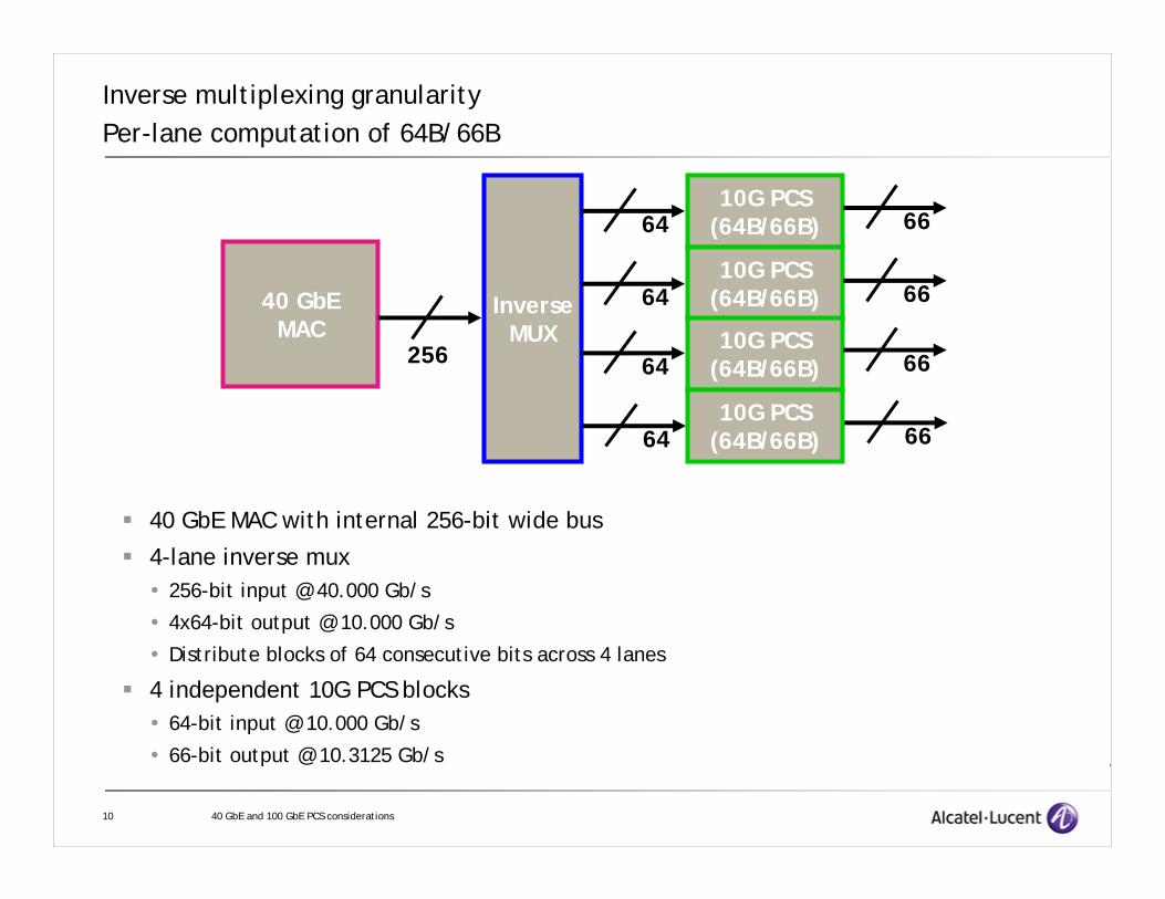
Inverse multiplexing granularityPer-lane computation of 64B/66B
40 GbE MAC with internal 256-bit wide bus
4-lane inverse mux256-bit input @ 40.000 Gb/s
4x64-bit output @ 10.000 Gb/s
Distribute blocks of 64 consecutive bits across 4 lanes
4 independent 10G PCS blocks64-bit input @ 10.000 Gb/s
66-bit output @ 10.3125 Gb/s
40 GbEMAC
10G PCS(64B/66B)
256
InverseMUX
64
64
64
64
10G PCS(64B/66B)
10G PCS(64B/66B)
10G PCS(64B/66B)
66
66
66
66

11 40 GbE and 100 GbE PCS considerations
Inverse multiplexing granularityBitstream View – Per lane computation of 64B/66B
64 bits 64 bits 64 bits 64 bits 64 bits 64 bits 64 bits64 bits
66 bits 66 bits
66 bits 66 bits
66 bits 66 bits
66 bits 66 bits
64 bits 64 bits
64 bits 64 bits
64 bits 64 bits
64 bits 64 bits
Inverse Mux 4x10G PCS Encode
40G MAC

12 40 GbE and 100 GbE PCS considerations
Inverse multiplexing granularitySerial computation of 64B/66B
40 GbE MAC with internal 256-bit wide bus
64B/66B PCS block @ 40G: 256-bit input @ 40.000 Gb/s
264-bit output @ 41.250 Gb/s
4-lane inverse mux264-bit input @ 41.250 Gb/s
4x66-bit output @ 10.3125 Gb/s
Distribute blocks of 66 consecutive bits across 4 lanes
40 GbEMAC
40G PCS(64B/66B)
256 264
InverseMUX
66666666
BLKAIS

13 40 GbE and 100 GbE PCS considerations
Inverse multiplexing granularityBitstream View – Serial computation of 64B/66B
64 bits 64 bits 64 bits 64 bits 64 bits 64 bits 64 bits64 bits
66 bits 66 bits 66 bits 66 bits 66 bits 66 bits 66 bits66 bits
40G PCS Encode
Inverse Mux
66 bits 66 bits
66 bits 66 bits
66 bits 66 bits
66 bits 66 bits
40G MAC

14 40 GbE and 100 GbE PCS considerations
Inverse Multiplexing GranularityImpact on multi-lane striping
• 10G Base-X interfaces do inverse multiplexing character by character across the lanes (10B codeword by 10B codeword).
• For 10 GbE, always know that you can have four consecutive bytes you can “steal” from the IPG for lane alignment marking
• With 66B codeword granularity, and four lanes (4x10 for 40 GbE or 4x25 for 100 GbE), the markers for alignment are separated by a minimum of 24 bytes from the first lane to the last (relative position within the XLGMII or CGMII).
• With 66B codeword granularity and 10 lanes (10x10 for 100 GbE), the markers for synchronization are separated by a minimum of 72 bytes from the first lane to the last (relative position within the CGMII)
• With 66B codeword granularity and 20 virtual lanes (20x5 for 100 GbE), the markers for synchronization are separated by a minimum of 152 bytes from the first lane to the last (relative position within the CGMII)
• No guarantee that IPGs will be large enough to accommodate lane alignment markers if inverse multiplexing is done on a 66B block basis, but an additional set of problems if inverse multiplexing is done on a byte basis
• Need to choose a lane synchronization marker that can either interrupt a packet, or can be transmitted out of band (Example: Cisco proposed CTBI/virtual lane approach would advocate the former)
15 40 GbE and 100 GbE PCS considerations
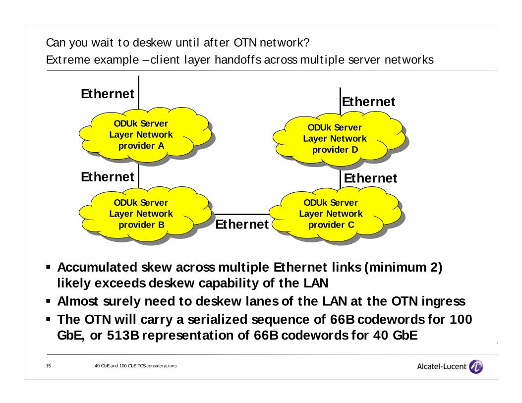
Can you wait to deskew until after OTN network?Extreme example – client layer handoffs across multiple server networks
ODUk ServerLayer Network
provider B
ODUk ServerLayer Network
provider B
ODUk ServerLayer Network
provider A
ODUk ServerLayer Network
provider A
ODUk ServerLayer Network
provider C
ODUk ServerLayer Network
provider C
ODUk ServerLayer Network
provider D
ODUk ServerLayer Network
provider D
Ethernet
Ethernet
Ethernet
Ethernet
Ethernet
Accumulated skew across multiple Ethernet links (minimum 2) likely exceeds deskew capability of the LANAlmost surely need to deskew lanes of the LAN at the OTN ingressThe OTN will carry a serialized sequence of 66B codewords for 100 GbE, or 513B representation of 66B codewords for 40 GbE

16 40 GbE and 100 GbE PCS considerations
PCS options based on whether lane alignment markers steal from the MAC bandwidth and whether or not they are carried across the OTN
Note: An implication of Options 2 and 3 is that (virtual) lane alignment markers will ALWAYS be present, even when a serial PMD exists for 40 GbE or 100 GbE. This may be needed anyway, if only to perform the electrical deskew across the CTBI/CFBI.
unlikelyunlikelyOption 4No
Option 3Option 2Option 1YesLAN interfaceDo lane alignment markers steal from MAC Bandwidth?
YesNo
No YesAre Lane alignment markers
carried across OTN?
OTN InterfaceIs space for lane alignment markers stolen
from MAC bandwidth

17 40 GbE and 100 GbE PCS considerations
Option Summary - Where in the parallel LAN stack does the 64B/66B encoded data for OTN come from?
• Option 1: Deskew LAN virtual lanes, decode 64B/66B, reinsert into IPG to reach full MAC rate, re-encode 64B/66B (and transcode to 512B/513B for 40 GbE) to carry across OTN
• Option 2: Deskew LAN virtual lanes, remove lane alignment markers from serialized 64B/66B data, and transport rate reduced bitstream (sans lane alignment markers, -0.0061% reduction in bandwidth) over OTN
• Option 3: Deskew LAN virtual lanes, leaving lane alignment markers in place to be re-distributed across lanes of the LAN at the far end OTN egress
• Option 4: Rather than deleting from IPG to make room for lane markers, LAN lanes run at 0.0061% higher bitrate to make room for lane markers “out of band”. Deskew and remove lane markers at OTN ingress. This option will also allow for no lane markers once there is a serial PMD for 40 GbE or 100 GbE.

18 40 GbE and 100 GbE PCS considerations
Example Data flow for 100 GbE, 4 lane LAN interfaceOptions 1, 2, 3 – Steal bandwidth for lane alignment markers from MAC
100 Gb/sAdd to IPG to restore MAC rateCGMII
99.993896484 Gb/sDecode 64B/66B
103.11870575 Gb/sDeskew virtual lanes, remove lane alignment markers
Rx PCS
10x10.3125 Gb/sTwo virtual lanes per physical laneRx CTBI
4x25.78125 Gb/sFive virtual lanes per physical laneTx gearbox PMA Tx PMDRx PMDRx gearbox PMA
10x10.3125 Gb/sTwo virtual lanes per physical laneTx CTBI
20x5.15625 Gb/sAdd lane alignment marker to each 16383 data or control 66B blocks per lane
20x5.155935287 Gb/sDivide into 20 virtual lanes
103.11870575 Gb/s64B/66B coding
99.993896484 Gb/sDelete from IPG to make room for lane alignment markers
Tx PCS
100 Gb/sCGMII
19 40 GbE and 100 GbE PCS considerations
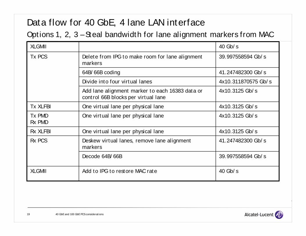
Data flow for 40 GbE, 4 lane LAN interfaceOptions 1, 2, 3 – Steal bandwidth for lane alignment markers from MAC
40 Gb/sAdd to IPG to restore MAC rateXLGMII
39.997558594 Gb/sDecode 64B/66B
41.247482300 Gb/sDeskew virtual lanes, remove lane alignment markers
Rx PCS
4x10.3125 Gb/sOne virtual lane per physical laneRx XLFBI
4x10.3125 Gb/sOne virtual lane per physical laneTx PMDRx PMD
4x10.3125 Gb/sOne virtual lane per physical laneTx XLFBI
4x10.3125 Gb/sAdd lane alignment marker to each 16383 data or control 66B blocks per virtual lane
4x10.311870575 Gb/sDivide into four virtual lanes
41.247482300 Gb/s64B/66B coding
39.997558594 Gb/sDelete from IPG to make room for lane alignment markers
Tx PCS
40 Gb/sXLGMII

20 40 GbE and 100 GbE PCS considerations
Example Data flow for 100 GbE, 4 lane LAN interface with Option 4Increase lane rate to accommodate lane alignment markers
100 Gb/sDecode 64B/66B
103.125 Gb/sDeskew virtual lanes, remove lane alignment markers
Rx PCS
10x10.31312946 Gb/sTwo virtual lanes per physical laneRx CTBI
4x25.78282366 Gb/sFive virtual lanes per physical laneTx gearbox PMA Tx PMDRx PMDRx gearbox PMA
10x10.31312946 Gb/sTwo virtual lanes per physical laneTx CTBI
20x5.15656473 Gb/sAdd lane alignment marker to each 16383 data or control 66B blocks per lane
20x5.15625 Gb/sDivide into 20 virtual lanes
103.125 Gb/s64B/66B codingTx PCS
100 Gb/sCGMII

21 40 GbE and 100 GbE PCS considerations
Data flow for 40 GbE, 4 lane LAN interface – Option 4Increase lane rate to accommodate lane alignment markers
40 Gb/sDecode 64B/66B
41.25 Gb/sDeskew virtual lanes, remove lane alignment markers
Rx PCS
4x10.31312946 Gb/sOne virtual lane per physical laneRx XLFBI
4x10.31312946 Gb/sOne virtual lane per physical laneTx PMDRx PMD
4x10.31312946 Gb/sOne virtual lane per physical laneTx XLFBI
4x10.3125 Gb/sAdd lane alignment marker to each 16383 data or control 66B blocks per virtual lane
4x10.3125 Gb/sDivide into four virtual lanes
41.25 Gb/s64B/66B codingTx PCS
40 Gb/sXLGMII

22 40 GbE and 100 GbE PCS considerations
Option 1 – Pure 64B/66B of CGMII or XLGMII over OTN
•This is the PCS that would likely be used if the only (or ANY) LAN interfaces being developed for 40 GbE and 100 GbE were serial interfaces
•Due to deletion of IPG to make room for lane alignment markers in the LAN, it is a different sequence of 66B blocks than is used in the LAN (the adaptation into OTN will reinsert the same amount of IPG, but not necessarily in the same places)
•May not be considered transparent by all customers
•Largest complexity of any of the options due to decode of 64B/66B, adjusting of IPG, and recoding of 64B/66B

23 40 GbE and 100 GbE PCS considerations
Option 2 or 4 for 40 GbE - Deskew and remove lane alignment markers before mapping into OTN
66B 66B 66B 66B 66B 66B 66B 66B 66B 66B 66B 66B 66B 66B 66B 66B
Delete from IPG, 64B/66B encode:
Inverse multiplex into lanes, add lane alignment markers:66B
66B
66B
66B
VL1
VL2
VL3
VL4
66B 66B 66B
66B 66B 66B
66B 66B 66B
66B 66B 66B
Deskew, remove lane alignment markers, transcode to 512B/513B:66B66B66B66B66B66B66B66B
513B
66B66B66B66B66B66B66B66B
513B

24 40 GbE and 100 GbE PCS considerations
Data flow for Adaptation of 40 GbE, 4 lane LAN interface into ODU3 – Option 2 – remove lane alignment markers
40.149716 Gb/sWorst case -20ppmOPU3 payload area
40.095312002 Gb/sWorst case +100ppm
40.091302872 Gb/sAdd Framing for 513B blocks
40.075678825 Gb/sTranscode 64B/66B to 512B/513B
41.247482300 Gb/sDeskew virtual lanes, remove lane alignment markers
OPU3 adaptation
4x10.3125 Gb/sOne virtual lane per physical lane with lane alignment markers
LAN PMD

25 40 GbE and 100 GbE PCS considerations
Option 2 or 4 for 100 GbE - Deskew and remove lane alignment markers before mapping into OTN
66B 66B ••• 66B 66B 66B 66B 66B 66B 66B 66B 66B 66B
Delete from IPG, 64B/66B encode:
Inverse multiplex into 20 virtual lanes, add lane alignment markers:
66B
66B
66B
VL1
VL2
VL20
66B 66B 66B 66B
66B 66B 66B 66B
66B 66B 66B 66B
Deskew, remove lane alignment markers, map into OPU4
•••
••• ••• •••
20 virtual lanes
20 blocks 20 blocks 20 blocks 20 blocks
66B 66B ••• 66B 66B 66B 66B 66B 66B 66B 66B 66B 66B••• ••• •••20 blocks 20 blocks 20 blocks 20 blocks
Rate reduced by 0.0061% due to shortening IPG to make room for lane alignment markers

26 40 GbE and 100 GbE PCS considerations
Data flow for Adaptation of 100 GbE, 4 lane LAN interface into ODU4 – Option 2 – remove lane alignment markers
103.12695504 Gb/sLeast possible nominal bitrate given ±20ppm clock tolerance
OPU4
4x25.78125 Gb/sFive virtual lanes per physical lane with lane alignment markers
LAN PMD
103.12901762 Gb/sWorst case +100ppm
103.11870575 Gb/sDeskew virtual lanes, remove lane alignment markers
OPU4 adaptation
10x10.3125 Gb/sTwo virtual lanes per physical lane with lane alignment markers
CTBI

27 40 GbE and 100 GbE PCS considerations
Option 3 for 40 GbE – Deskew and keep lane alignment markers when mapping into OTN
66B 66B 66B 66B 66B 66B 66B 66B 66B 66B 66B 66B 66B 66B 66B 66B
Delete from IPG, 64B/66B encode:
Inverse multiplex into lanes, add lane alignment markers:66B
66B
66B
66B
VL1
VL2
VL3
VL4
66B 66B 66B
66B 66B 66B
66B 66B 66B
66B 66B 66B
Deskew, keep lane alignment markers, transcode to 512B/513B:66B66B66B66BVL1VL2VL3VL4
513B
66B66B66B66B66B66B66B66B
513B
66B66B66B66B
513B

28 40 GbE and 100 GbE PCS considerations
Data flow for Adaptation of 40 GbE, 4 lane LAN interface into ODU3 – Option 3 – keep lane alignment markers
40.149716 Gb/sWorst case -20ppmOPU3 payload area
40.097759375 Gb/sWorst case +100ppm
40.093750000 Gb/sAdd Framing for 513B blocks
40.078125000 Gb/sTranscode 64B/66B to 512B/513B
41.25 Gb/sDeskew virtual lanes, keep lane alignment markersOPU3 adaptation
4x10.3125 Gb/sOne virtual lane per physical lane with lane alignment markers
LAN PMD

29 40 GbE and 100 GbE PCS considerations
Option 3 for 100 GbE – Deskew, leaving lane alignment markers in place, and map into OTN
66B 66B ••• 66B 66B 66B 66B 66B 66B 66B 66B 66B 66B
Delete from IPG, 64B/66B encode:
Inverse multiplex into 20 virtual lanes, add lane alignment markers:
66B
66B
66B
VL1
VL2
VL20
66B 66B 66B 66B
66B 66B 66B 66B
66B 66B 66B 66B
Deskew, keep lane alignment markers, map into OPU4
•••
••• ••• •••20 blocks 20 blocks 20 blocks 20 blocks
66B 66B ••• 66B VL1 VL2 VL20 66B 66B 66B 66B 66B 66B••• ••• •••20 blocks 20 blocks 20 blocks 20 blocks
Lane alignment markers replace 0.0061% of IPG – same PCS encoded rate
30 40 GbE and 100 GbE PCS considerations
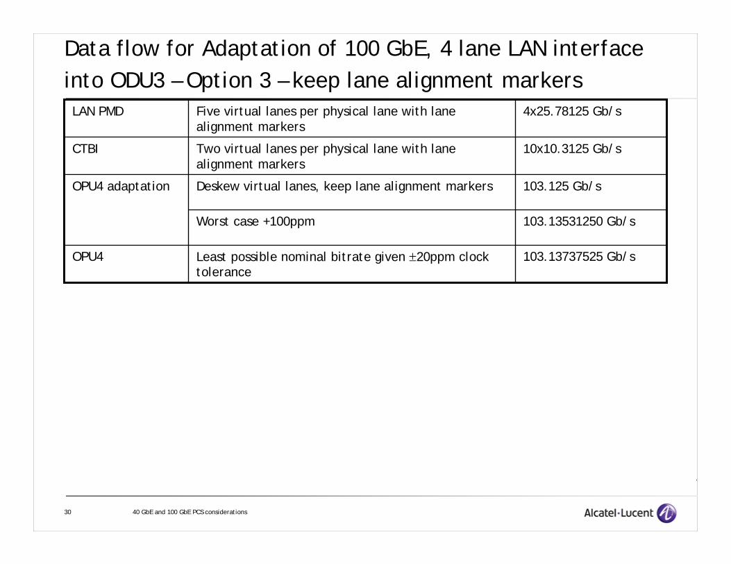
Data flow for Adaptation of 100 GbE, 4 lane LAN interface into ODU3 – Option 3 – keep lane alignment markers
103.13737525 Gb/sLeast possible nominal bitrate given ±20ppm clock tolerance
OPU4
4x25.78125 Gb/sFive virtual lanes per physical lane with lane alignment markers
LAN PMD
103.13531250 Gb/sWorst case +100ppm
103.125 Gb/sDeskew virtual lanes, keep lane alignment markersOPU4 adaptation
10x10.3125 Gb/sTwo virtual lanes per physical lane with lane alignment markers
CTBI

31 40 GbE and 100 GbE PCS considerations
Data flow for Adaptation of 100 GbE, 4 lane LAN interface into ODU4 – Option 4 – remove lane alignment markers
103.137375248 Gb/sLeast possible nominal bitrate given ±20ppm clock tolerance
OPU4
4x25.78282366 Gb/sFive virtual lanes per physical lane with lane alignment markers
LAN PMD
103.1353125 Gb/sWorst case +100ppm
103.125 Gb/sDeskew virtual lanes, remove lane alignment markers
OPU4 adaptation
10x10.31312946 Gb/sTwo virtual lanes per physical lane with lane alignment markers
CTBI

32 40 GbE and 100 GbE PCS considerations
Data flow for Adaptation of 40 GbE, 4 lane LAN interface into ODU3 – Option 4 – remove lane alignment markers
40.149716 Gb/sWorst case -20ppmOPU3 payload area
40.097759375 Gb/sWorst case +100ppm
40.09375 Gb/sAdd Framing for 513B blocks
40.078125 Gb/sTranscode 64B/66B to 512B/513B
41.25 Gb/sDeskew virtual lanes, remove lane alignment markers
OPU3 adaptation
4x10.31312946 Gb/sOne virtual lane per physical lane with lane alignment markers
LAN PMD

33 40 GbE and 100 GbE PCS considerations
Alignment marker format• Should be 66 bits in length• Should identify (virtual) lane number• Could include other info (e.g., error control)• Should be DC balanced and have average clock content if not scrambled
10 ~VL# VL#~BIP BIPFrm1 Frm2 TBDTBD
10 0x55 0x4b0x55 0x4bBlockType= 0x1e 0x4b 0x4b0x55
From gustlin_01_0107
VL#
From gustlin_01_0907 (early version)
Frm1, Frm2 could be SONET A1, A2 (0xf628) or a new one (e.g., 0x5566)
• 2nd proposal has better DC balance• 1st proposal stays within transcodable space of control block types, allowing for
Option 3 transcoding to 512B/513B for 40 GbE keeping alignment markers• 2nd proposal does not preserve 4-bit Hamming distance between control block
types (may not be important depending on framing algorithm)• Room for only one more control block type and still transcode to 512B/513B

34 40 GbE and 100 GbE PCS considerations
Conclusions• Inverse multiplexing across the lanes of a LAN interface should be done on an
8-byte (66B codeword) boundary• Several viable options to establish relationship between the multi-lane LAN
PCS and the 64B/66B or 512B/513B encoded bitstream to be mapped into OTN• Easiest and most transparent options include:
Option 3: deskew but keep the virtual lane alignment markers in the OTN transported bitstream
This would require that virtual lane marking is done even when IEEE 802.3 defines a serial PMD for 40 GbE or 100 GbE;but this may be necessary anyway for electrical deskew across a CTBI or XLFBI type interfaceThe alignment words need to be transcodable for 40 GbE
Option 4: deskew and remove lane alignment markers which are accommodated by increasing the LAN lane rate rather than stealing from the MAC
• Care should be taken in choosing the alignment word format to avoid expanding the 66B codeword space or to create difficulty for transcoding to 512B/513B in 40 GbE