4.11.4 storage 4.11.4.1 schedule - optiview usa › wp-content › uploads › 2018 › 11 ›...
TRANSCRIPT

Standalone DVR User’s Manual
171
4.11.4 Storage
4.11.4.1 Schedule
4.11.4.1.1 Record
Note:
You need to have proper rights to implement the following operations. Please make
sure the HDDs have been properly installed.
After the system booted up, it is in default 24-hour regular mode. You can set record type
and time in schedule interface.
In the main menu, from Setting->Storage->Schedule, you can go to schedule menu.
See Figure 4-128.
Please note you need to go to main menu->Setting->System->General->Holiday to
set holiday date first, otherwise, there is no holiday setup item.
Channel: Please select the channel number first. You can select “all” if you want to
set for the whole channels.
: Sync connection icon. Select icon of several dates, all checked items
can be edited together. Now the icon is shown as .
: Click it to delete a record type from one period.
Record Type: Please check the box to select corresponding record type. There are
five types: Regular/MD (motion detect)/Alarm/MD&Alarm/Intelligent.
Week day: There are eight options: ranges from Saturday to Sunday and all.
Holiday: It is to set holiday setup. Please note you need to go to the General interface
(Main Menu->System->General) to add holiday first. Otherwise you can not see this
item.
Pre-record: System can pre-record the video before the event occurs into the file. The
value ranges from 1 to 30 seconds depending on the bit stream.
Redundancy: System supports redundancy backup function. You can highlight
Redundancy button to activate this function. Please note, before enable this function,
please set at least one HDD as redundant. (Main menu->Setting->Storage->HDD
Manager). Please note this function is null if there is only one HDD.
ANR: Check the ANR box, DVR can auto record once the network camera is offline.
You can set the record period here. Please make sure you connected camera
supports the ANR function.
Period setup: Click button after one date or a holiday, you can see an interface
shown as in Figure 4-129.There are four record types: regular, motion detection (MD),
Alarm, MD & alarm.
Please following the steps listed below to draw the period manually.
Select a channel you want to set. See Figure 4-125.

Standalone DVR User’s Manual
172
Figure 4-125
Set record type. See Figure 4-126.
Figure 4-126
Please draw manually to set record period. There are six periods in one day. See
Figure 4-127.
Figure 4-127
Please highlight icon to select the corresponding function. After completing all the
setups please click save button, system goes back to the previous menu.
There are color bars for your reference. Green color stands for regular recording,
yellow color stands for motion detection and red color stands for alarm recording. The
white means the MD and alarm record is valid. Once you have set to record when the
MD and alarm occurs, system will not record neither motion detect occurs nor the
alarm occurs.

Standalone DVR User’s Manual
173
Figure 4-128
Figure 4-129
4.11.4.1.1.1 Quick Setup
Copy function allows you to copy one channel setup to another. After setting in channel 1,
click Copy button, you can go to interface Figure 4-130. You can see current channel
name is grey such as channel 1. Now you can select the channel you wan to paste such
as channel 5/6/7. If you want to save current setup of channel 1 to all channels, you can
click the first box “ALL”. Click the OK button to save current copy setup. Click the OK
button in the Encode interface, the copy function succeeded.

Standalone DVR User’s Manual
174
Figure 4-130
4.11.4.1.1.2 Redundancy
Redundancy function allows you to memorize record file in several disks. When there
is file damage occurred in one disk, there is a spare one in the other disk. You can use
this function to maintain data reliability and safety.
In the main menu, from Setting->Storage-> Schedule, you can highlight
redundancy button to enable this function.
In the main menu, from Main menu->Setting->Storage->HDD Manager, you can set
one or more disk(s) as redundant. You can select from the dropdown list. System
auto overwrites old files once hard disk is full.
Please note only read/write disk or read-only disk can backup file and support file
search function, so you need to set at least one read-write disk otherwise you can not
record video.
Note
About redundancy setup:
If current channel is not recording, current setup gets activated when the channel
begin recording the next time.
If current channel is recording now, current setup will get activated right away, the
current file will be packet and form a file, then system begins recording as you have
just set.
After all the setups please click save button, system goes back to the previous menu.
Playback or search in the redundant disk.
There are two ways for you to playback or search in the redundant disk.
Set redundant disk(s) as read-only disk or read-write disk (Main
menu->Setting->Storage->HDD Manager)). System needs to reboot to get setup
activated. Now you can search or playback file in redundant disk.
Dismantle the disk and play it in another PC.
4.11.4.1.2 Snapshot
4.11.4.1.2.1 Schedule Snapshot
On the preview interface, right click mouse and then select Manual->Record, or in the
main menu, from Setting->Storage->Record, check the box to enable snapshot
function of corresponding channels. See Figure 4-131.

Standalone DVR User’s Manual
175
In main menu, from Setting->Camera->Encode->Snapshot interface, here you can
input snapshot mode as regular, size, quality and frequency. See Figure 4-132.
In main menu, from Setting->Camera->Encode->Schedule interface, please enable
snapshot function. See interface on the right of Figure 4-133.
Please refer to the following figure for detailed information.
Figure 4-131
Figure 4-132
Standalone DVR User’s Manual
176
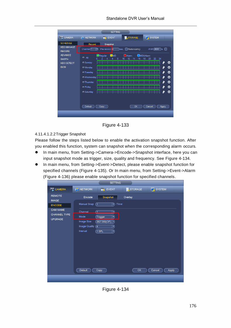
Figure 4-133
4.11.4.1.2.2 Trigger Snapshot
Please follow the steps listed below to enable the activation snapshot function. After
you enabled this function, system can snapshot when the corresponding alarm occurs.
In main menu, from Setting->Camera->Encode->Snapshot interface, here you can
input snapshot mode as trigger, size, quality and frequency. See Figure 4-134.
In main menu, from Setting->Event->Detect, please enable snapshot function for
specified channels (Figure 4-135). Or In main menu, from Setting->Event->Alarm
(Figure 4-136) please enable snapshot function for specified channels.
Figure 4-134

Standalone DVR User’s Manual
177
Figure 4-135
Figure 4-136
4.11.4.1.2.3 Priority
Please note the activation snapshot has the higher priority than schedule snapshot. If
you have enabled these two types at the same time, system can activate the activation
snapshot when an alarm occurs, and otherwise system just operates the schedule

Standalone DVR User’s Manual
178
snapshot.
4.11.4.1.2.4 Image FTP
In the main menu, from Setting->Network->FTP, you can set FTP server information.
Please enable FTP function and then click save button. See Figure 4-137.
Please boot up corresponding FTP server.
Please enable schedule snapshot (Chapter 4.11.4.1.2.1) or activation snapshot
(Chapter 4.11.4.1.2.2) first, now system can upload the image file to the FTP server.
Figure 4-137
4.11.4.2 HDD Manager
Here is for you to view and implement hard disk management. See Figure 4-138.
You can see current HDD type, status, capacity and etc. The operation includes format
HDD, and change HDD property (read and write/read-only/redundancy).
Please input the
corresponding information
here, if you just upload the
image FTP.

Standalone DVR User’s Manual
179
Figure 4-138
4.11.4.3 Record
4.11.4.3.1 Record Control
Note:
You need to have proper rights to implement the following operations. Please make
sure the HDD has been properly installed.
There are three ways for you to go to manual record menu.
Right click mouse and then select Manual->Record.
In the main menu, from Setting->Storage->Record.
In live viewing mode, click record button in the front panel or record button in the
remote control.
System supports main stream and sub stream. There are three statuses:
schedule/manual/stop. See Figure 4-139. Please highlight icon“○” to select
corresponding channel.
Manual: The highest priority. After manual setup, all selected channels will begin
ordinary recording.
Schedule: Channel records as you have set in recording setup (Main
Menu->Setting->System->>Schedule)
Stop: Current channel stops recording.
All: Check All button after the corresponding status to enable/disable all-channel
schedule/manual record or enable/disable all channels to stop record.

Standalone DVR User’s Manual
180
Figure 4-139
4.11.4.3.2 Snapshot Operation
Check the corresponding box to enable/disable schedule snapshot function. See
Figure 4-140.
Figure 4-140
Tips
You can check All button after the corresponding status to enable/disable all-channel

Standalone DVR User’s Manual
181
snapshot function.
4.11.4.4 Advanced
It is to set HDD group, and HDD group setup for main stream, sub stream and snapshot
operation
4.11.4.4.1 HDD
Important
HDD group and quota mode can not be valid at the same time. System needs to
restart once you change the mode here.
The HDD group mode is shown as in Figure 4-141.
HDD: Here you can view the HDD amount the device can support.
Group: It lists the HDD Group number of current hard disk.
Figure 4-141
Please select the correspond group from the dropdown list and then click Apply button.
Click main stream/sub stream/snapshot button to set corresponding HDD group
information. See Figure 4-142.

Standalone DVR User’s Manual
182
Figure 4-142
Figure 4-143

Standalone DVR User’s Manual
183
Figure 4-144
4.11.4.5 Quota
Here you can set channel storage capacity. See Figure 4-145.
Select a channel from the dropdown list and then select corresponding HDD quota.
Figure 4-145
Click Quota Statistics, you can go to the following interface. You can view HDD capacity

Standalone DVR User’s Manual
184
you set for each channel. See Figure 4-146.
Figure 4-146
4.11.4.6 HDD Detect
The HDD detect function is to detect HDD current status so that you can clearly
understand the HDD performance and replace the malfunction HDD.
There are two detect types:
Quick detect: It is to detect the storaged files on the HDD. You can use format
function to repair the bad track. System can not detect the bad track if there is no
record on the HDD.
Global detect: It detects the whole HDD. The process may take a long time and may
affect the HDD that is saving the record. If it detects the bad track, it may result from
the damaged HDD.
4.11.4.6.1 Manual Detect
The manual detect interface is shown as below. See Figure 4-147.
Please select detect type and HDD. Click start detect to begin. You can view the
corresponding detect information.

Standalone DVR User’s Manual
185
Figure 4-147
4.11.4.6.2 Detect Report
After the detect operation, you can go to the detect report to view corresponding
information.
The detect report interface is shown as below. See Figure 4-148.
Figure 4-148

Standalone DVR User’s Manual
186
Click View, you can see the detailed information such as detect result, backup and
S.M.A.R.T. See Figure 4-149 and Figure 4-150.
Figure 4-149
Figure 4-150
4.11.4.7 ISCSI

Standalone DVR User’s Manual
187
iSCSI function is for some series product only.
You can set the network mapping HDD so that device can storage audio/video on the
network HDD.
From Main menu->Setting->Storage->ISCSI, you can go to the following interface. See
Figure 4-151.
Server IP address: It is to input ISCSI server IP address.
Port: It is to input ISCSI server port value. The default setup is 3260.
User name/password: It is to input ISCSI server user name and password. Check the
Anonymous button if it supports anonymous login.
Set path: You can click the Set path button to select the remote storage path. Please
note each path here stands for one ISCSI share disk. The path has been generated
when it is created at the server.
Add: After you input the above information, click add button to add the new
information to the list.
Figure 4-151
Click Ok button to complete the setup.
Tips
Click the modify/delete button to change or remove the ISCSI disk.
Now, from the main menu->setting->Storage-> HDD manage, you can see the following
interface. See Figure 4-152.

Standalone DVR User’s Manual
188
Figure 4-152
4.11.4.8 RAID
RAID function is for some series product such as advanced 1080P 2U RAID series only.
Right now system supports RAID0/RAID1/RAID5/RAID10. Please refer to Appendix G for
detailed information.
4.11.4.8.1 RAID Config
The RAID configuration interface is shown as in Figure 4-153. In this interface, you can
set RAID type and settings.
Create manually: Check HDD manually to crate RAID.
Create RAID: Click it to automatically create RAID.
For create RAID function, you can select the physical HDD that does not included in the
RAID group or the created disk array to create a RADI5. You can refer to the following
situations:
There is no RAID, no hotspare disk: System directly creates the RAID5 and creates
one hotspare disk at the same time.
There is no RAID, but there is a hotspare disk: System creates the RAID5 only. It
uses previous hotspare disk.
There is RAID: System cancel the previous RAID setup and then create the new
RAID5. System creates the hotspare disk if there is no one. System uses previous
hotspare disk if there is hotspare disk available.
The background will format the virtual disk.

Standalone DVR User’s Manual
189
Figure 4-153
4.11.4.8.2 RAID Info
It is to display RAID name, space, type, member HDD, hotspare HDD, status and etc.
Here you can delete RAID. See Figure 4-154.

Standalone DVR User’s Manual
190
Figure 4-154
4.11.4.8.3 Hotspare Disk
In this interface you can add/delete hotspare HDD. See Figure 4-155.

Standalone DVR User’s Manual
191
Figure 4-155
Click , you can set corresponding disk to the hotspare disk.
Private hotspare: Please select the RAID disk to be added. It becomes the hotspare
disk of the specified RAID.
Global hotspare: It is not for just one RAID. It is for all RAID disks.
Tips
Click the to delete the hotspare disk.
4.11.5 System
4.11.5.1 General
4.11.5.1.1 Device
General setting includes the following items. See Figure 4-156.
Device ID: Please input a corresponding device name here.
Device No: Here you can set device number.
Language: System supports various languages: Chinese (simplified), Chinese
(Traditional), English, Italian, Japanese, French, Spanish (All languages listed here
are optional. Slight difference maybe found in various series.)
Video standard: There are two formats: NTSC and PAL.
HDD full: Here is for you to select working mode when hard disk is ful l. There are two
options: stop recording or rewrite. If current working HDD is overwritten or the current
HDD is full while the next HDD is no empty, then system stops recording, If the