4150 bulletin prntr - bid on equipment files/itt goulds 4150 process pumps... · goulds 4150...
TRANSCRIPT
Goulds 4150 Process Pumps designed for corrosive services
Goulds 4150
2
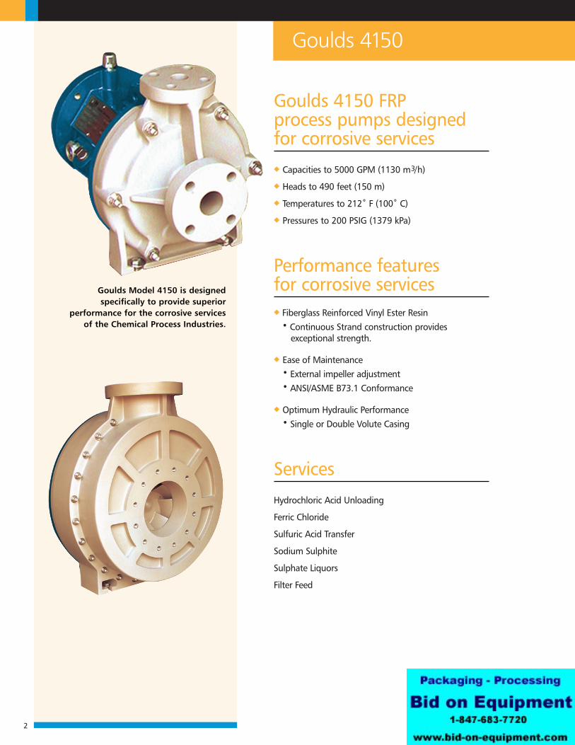
Goulds Model 4150 is designedspecifically to provide superior
performance for the corrosive servicesof the Chemical Process Industries.
Goulds 4150 FRPprocess pumps designedfor corrosive services◆ Capacities to 5000 GPM (1130 m3/h)
◆ Heads to 490 feet (150 m)
◆ Temperatures to 212˚ F (100˚ C)
◆ Pressures to 200 PSIG (1379 kPa)
Performance featuresfor corrosive services◆ Fiberglass Reinforced Vinyl Ester Resin
• Continuous Strand construction providesexceptional strength.
◆ Ease of Maintenance• External impeller adjustment• ANSI/ASME B73.1 Conformance
◆ Optimum Hydraulic Performance• Single or Double Volute Casing
ServicesHydrochloric Acid Unloading
Ferric Chloride
Sulfuric Acid Transfer
Sodium Sulphite
Sulphate Liquors
Filter Feed
Goulds 4150
3
Thermoset FiberglassReinforced Plastic (FRP)Thermoset materials outperform other materials such asthermoplastics in chemical resistance, thermal stability andoverall durability.
Fiberglass reinforced plastic is increasingly being used in thepump industry for its easy handling, efficient flow, strengthand stability. Using a controlled placement of continuous-strand fiberglass mat in high stress areas providescomponents with excellent durability and corrosion resistance.
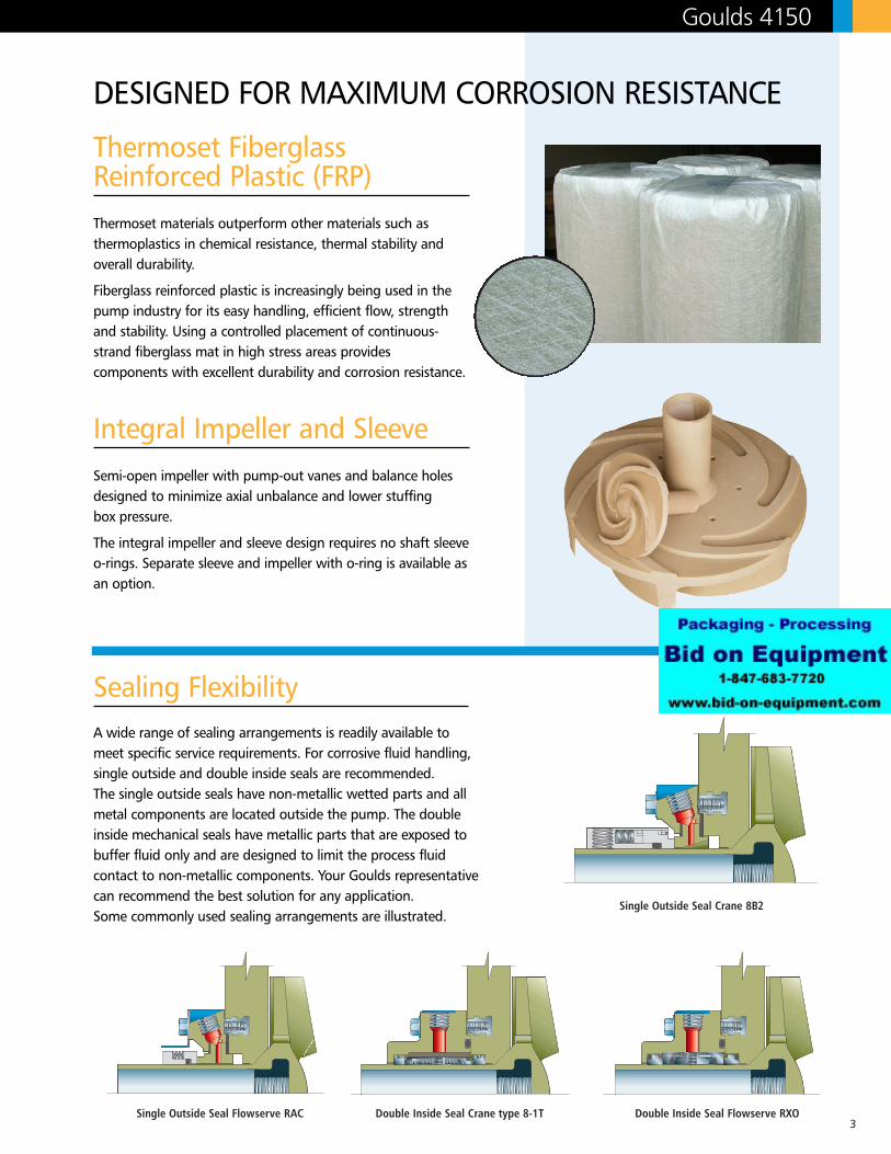
Integral Impeller and SleeveSemi-open impeller with pump-out vanes and balance holesdesigned to minimize axial unbalance and lower stuffingbox pressure.
The integral impeller and sleeve design requires no shaft sleeveo-rings. Separate sleeve and impeller with o-ring is available asan option.
DESIGNED FOR MAXIMUM CORROSION RESISTANCE
Single Outside Seal Crane 8B2
Single Outside Seal Flowserve RAC Double Inside Seal Crane type 8-1T Double Inside Seal Flowserve RXO
A wide range of sealing arrangements is readily available tomeet specific service requirements. For corrosive fluid handling,single outside and double inside seals are recommended.The single outside seals have non-metallic wetted parts and allmetal components are located outside the pump. The doubleinside mechanical seals have metallic parts that are exposed tobuffer fluid only and are designed to limit the process fluidcontact to non-metallic components. Your Goulds representativecan recommend the best solution for any application.Some commonly used sealing arrangements are illustrated.
Sealing Flexibility
Goulds 4150
4
Internal Cover FlushRemoves seal heat by circulating high pressure liquid internallythrough the drilled cover to the seal chamber and back to thelow pressure side of the pump.
This option eliminates the need for external flushing of singlemechanical seals from the pump discharge, which also eliminatesthe possible breakage of external tubing and fittings.
LowPressureLiquid
HighPressureLiquid
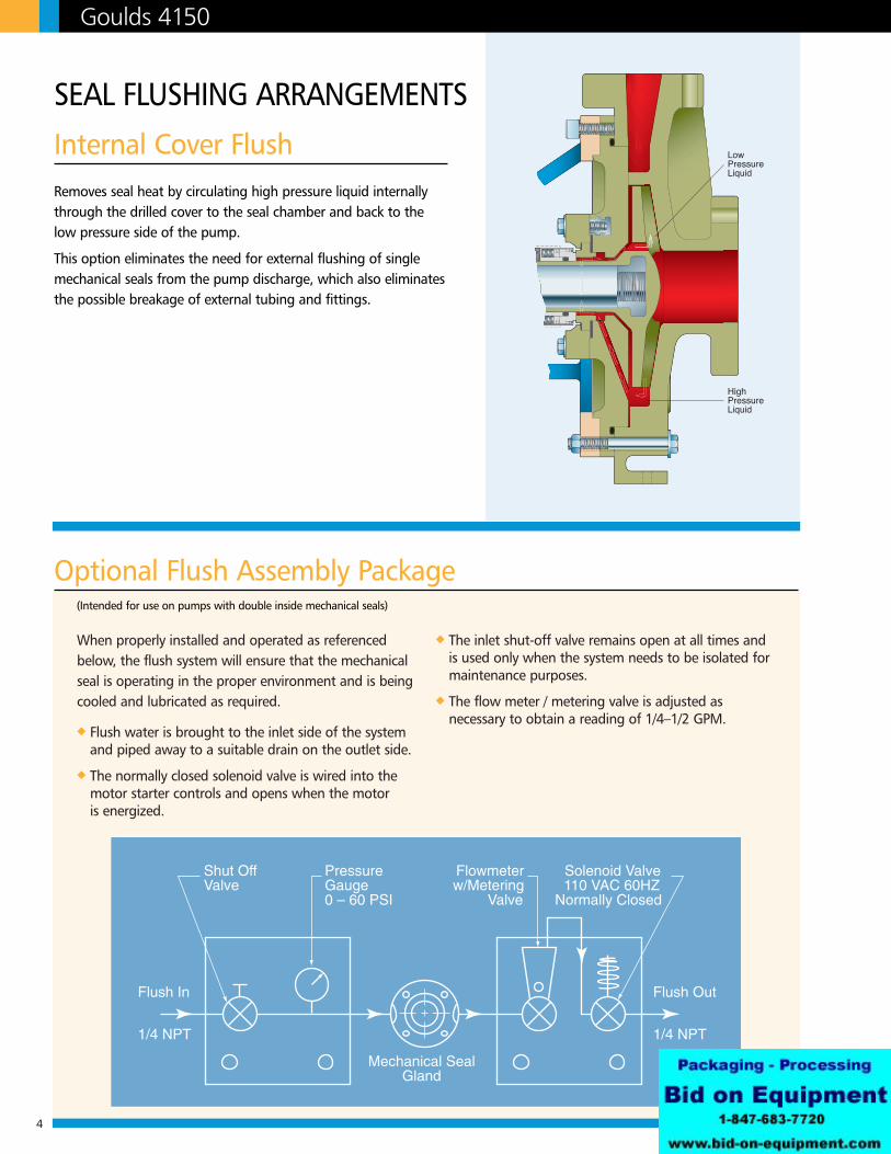
When properly installed and operated as referencedbelow, the flush system will ensure that the mechanicalseal is operating in the proper environment and is beingcooled and lubricated as required.
◆ Flush water is brought to the inlet side of the systemand piped away to a suitable drain on the outlet side.
◆ The normally closed solenoid valve is wired into themotor starter controls and opens when the motoris energized.
◆ The inlet shut-off valve remains open at all times andis used only when the system needs to be isolated formaintenance purposes.
◆ The flow meter / metering valve is adjusted asnecessary to obtain a reading of 1/4–1/2 GPM.
Flush In
Shut OffValve
1/4 NPT
Flush Out
1/4 NPT
PressureGauge0 – 60 PSI
Flowmeterw/Metering
Valve
Solenoid Valve110 VAC 60HZ
Normally Closed
Mechanical SealGland
Optional Flush Assembly Package(Intended for use on pumps with double inside mechanical seals)
SEAL FLUSHING ARRANGEMENTS
Goulds 4150
5
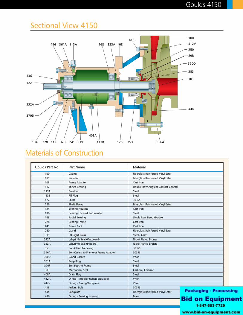
Sectional View 4150
Materials of Construction
Goulds Part No. Part Name Material
100 Casing Fiberglass Reinforced Vinyl Ester
101 Impeller Fiberglass Reinforced Vinyl Ester
108 Frame Adapter Cast Iron
112 Thrust Bearing Double Row Angular Contact Conrad
113A Breather Steel
113B Fill Plug Steel
122 Shaft 303SS
126 Shaft Sleeve Fiberglass Reinforced Vinyl Ester
134 Bearing Housing Cast Iron
136 Bearing Locknut and washer Steel
168 Radial Bearing Single Row Deep Groove
228 Bearing Frame Cast Iron
241 Frame Foot Cast Iron
250 Gland Fiberglass Reinforced Vinyl Ester
319 Oil Sight Glass Steel / Glass
332A Labyrinth Seal (Outboard) Nickel Plated Bronze
333A Labyrinth Seal (Inboard) Nickel Plated Bronze
353 Bolt-Gland to Casing 303SS
356A Bolt-Casing to Frame or Frame Adapter 303SS
360Q Gland Gasket Viton
361A Snap Ring Steel
370F Bolt-Foot to Frame Steel
383 Mechanical Seal Carbon / Ceramic
408A Drain Plug Steel
412A O-ring - Impeller (when provided) Viton
412V O-ring - Casing/Backplate Viton
418 Jacking Bolt 303SS
444 Backplate Fiberglass Reinforced Vinyl Ester
496 O-ring - Bearing Housing Buna
100
412V
250
89B
383
360Q
101
444
418108333A168113A361A496
113B 353126 356A
408A
319241370F112228134
136
122
332A
370D
6
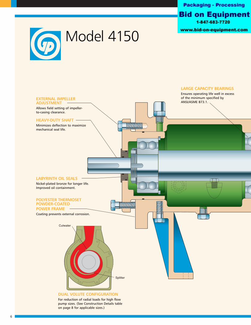
Model 4150
EXTERNAL IMPELLERADJUSTMENTAllows field setting of impeller-to-casing clearance.
HEAVY-DUTY SHAFTMinimizes deflection to maximizemechanical seal life.
LABYRINTH OIL SEALSNickel-plated bronze for longer life.Improved oil containment.
POLYESTER THERMOSETPOWDER-COATEDPOWER FRAMECoating prevents external corrosion.
LARGE CAPACITY BEARINGSEnsures operating life well in excessof the minimum specified byANSI/ASME B73.1.
Splitter
Cutwater
DUAL VOLUTE CONFIGURATIONFor reduction of radial loads for high flowpump sizes. (See Construction Details tableon page 8 for applicable sizes.)
7
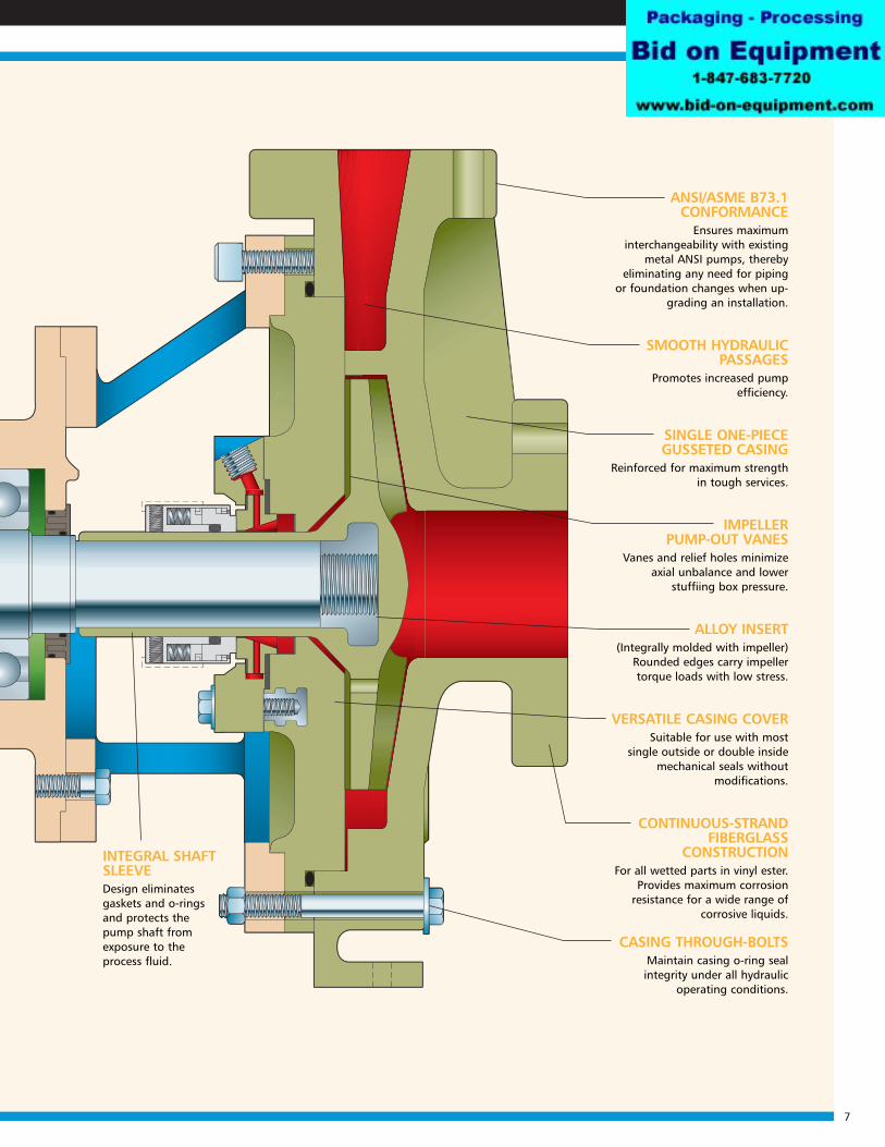
ANSI/ASME B73.1CONFORMANCE
Ensures maximuminterchangeability with existing
metal ANSI pumps, therebyeliminating any need for piping
or foundation changes when up-grading an installation.
SMOOTH HYDRAULICPASSAGES
Promotes increased pumpefficiency.
SINGLE ONE-PIECEGUSSETED CASING
Reinforced for maximum strengthin tough services.
IMPELLERPUMP-OUT VANES
Vanes and relief holes minimizeaxial unbalance and lower
stuffiing box pressure.
ALLOY INSERT(Integrally molded with impeller)
Rounded edges carry impellertorque loads with low stress.
VERSATILE CASING COVERSuitable for use with most
single outside or double insidemechanical seals without
modifications.
CONTINUOUS-STRANDFIBERGLASS
CONSTRUCTIONFor all wetted parts in vinyl ester.
Provides maximum corrosionresistance for a wide range of
corrosive liquids.
CASING THROUGH-BOLTSMaintain casing o-ring sealintegrity under all hydraulic
operating conditions.
INTEGRAL SHAFTSLEEVEDesign eliminatesgaskets and o-ringsand protects thepump shaft fromexposure to theprocess fluid.
Goulds 4150
8
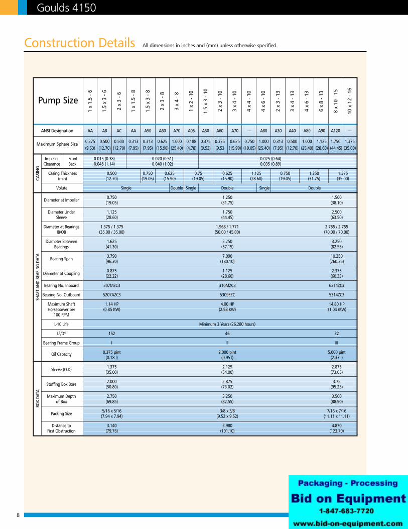
Construction Details All dimensions in inches and (mm) unless otherwise specified.
Pump Size1
x 1.
5 - 6
1.5
x 3
- 6
2 x
3 - 6
1 x
1.5
- 8
1.5
x 3
- 8
2 x
3 - 8
3 x
4 - 8
1 x
2 - 1
0
1.5
x 3
- 10
2 x
3 - 1
0
3 x
4 - 1
0
4 x
4 - 1
0
4 x
6 - 1
0
2 x
3 - 1
3
3 x
4 - 1
3
4 x
6 - 1
3
6 x
8 - 1
3
8 x
10 -
15
ANSI Designation AA AB AC AA A50 A60 A70 A05 A50 A60 A70 — A80 A30 A40 A80 A90 A120 —
Maximum Sphere Size 0.375 0.500 0.500 0.313 0.313 0.625 1.000 0.188 0.375 0.375 0.625 0.750 1.000 0.313 0.500 1.000 1.125 1.750 1.375(9.53) (12.70) (12.70) (7.95) (7.95) (15.90) (25.40) (4.78) (9.53) (9.53 (15.90) (19.05) (25.40) (7.95) (12.70) (25.40) (28.60) (44.45) (35.00)
Impeller Front 0.015 (0.38) 0.020 (0.51) 0.025 (0.64)Clearance Back 0.045 (1.14) 0.040 (1.02) 0.035 (0.89)
Casing Thickness 0.500 0.750 0.625 0.75 0.625 1.125 0.750 1.250 1.375(min) (12.70) (19.05) (15.90) (19.05) (15.90) (28.60) (19.05) (31.75) (35.00)
Volute Single Double Single Double Single Double
Diameter at Impeller 0.750 1.250 1.500(19.05) (31.75) (38.10)
Diameter Under 1.125 1.750 2.500Sleeve (28.60) (44.45) (63.50)
Diameter at Bearings 1.375 / 1.375 1.968 / 1.771 2.755 / 2.755IB/OB (35.00 / 35.00) (50.00 / 45.00) (70.00 / 70.00)
Diameter Between 1.625 2.250 3.250Bearings (41.30) (57.15) (82.55)
Bearing Span 3.790 7.090 10.250(96.30) (180.10) (260.35)
Diameter at Coupling 0.875 1.125 2.375(22.22) (28.60) (60.33)
Bearing No. Inboard 307MZC3 310MZC3 6314ZC3
Bearing No. Outboard 5207AZC3 5309EZC 5314ZC3
Maximum Shaft 1.14 HP 4.00 HP 14.80 HPHorsepower per (0.85 KW) (2.98 KW) 11.04 (KW)
100 RPM
L-10 Life Minimum 3 Years (26,280 hours)
L3/D4 152 46 32
Bearing Frame Group I II III
Oil Capacity 0.375 pint 2.000 pint 5.000 pint(0.18 l) (0.95 l) (2.37 l)
Sleeve (O.D) 1.375 2.125 2.875(35.00) (54.00) (73.05)
Stuffing Box Bore 2.000 2.875 3.75(50.80) (73.02) (95.25)
Maximum Depth 2.750 3.250 3.500of Box (69.85) (82.55) (88.90)
Packing Size 5/16 x 5/16 3/8 x 3/8 7/16 x 7/16(7.94 x 7.94) (9.52 x 9.52) (11.11 x 11.11)
Distance to 3.140 3.980 4.870First Obstruction (79.76) (101.10) (123.70)
CASI
NG
SHAF
T AN
D BE
ARIN
G DA
TABO
X DA
TA
10 x
12
- 16
Goulds 4150
9
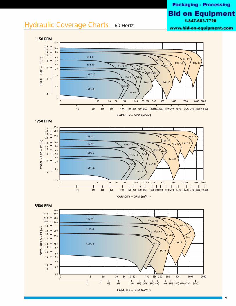
Hydraulic Coverage Charts – 60 Hertz
1x11/2-611/2 x3-6
2x3-6
3x4-8
2x3-811/2 x3-81x11/2 -8
1x2-10
2x3-13
11/2 x3-102x3-10
3x4-10 4x4-10
4x6-10
3x4-13
4x6-136x8-13
8x10-15
10x12-16
(1) (2) (3) (5) (10) (15) (20) (30) (40) (60) (80)( 100) (150) (200)
CAPACITY – GPM (m3/hr)
0 10 20 30 50 100 150 200 300 500 1000 2000 4000 6000
(300) (500) (700) (1000) (1500)
150
100
80
6050
40
30
20
10
5
(35)(30)(25)(20)
(15)
(10)
(5)
(2)
TOTA
L H
EAD
– F
T (m
)
(1) (2) (3) (5) (10) (15) (20) (30) (40) (60) (80) (100) (150) (200)
CAPACITY – GPM (m3/hr)
0 10 20 30 50 100 150 200 300 500 1000 2000 4000 6000
(300) (500) (700) (1000) (1500)
250
200
150
100
80
605040
30
20
10
(70)(60)(50)
(40)
(30)(25)(20)
(15)
(10)
(5)
TOTA
L H
EAD
– F
T (m
)
1x11/2-6
11/2x3-6
2x3-6
3x4-8
2x3-811/ 2 x3-81x11/2-8
1x2-10
2x3-13
11/2 x3-102x3-10
3x4-10 4x4-10
4x6-10
3x4-134x6-13 6x8-13
8x10-15
(1) (2) (3) (5) (10) (15) (20) (30) (40) (60) (80)
CAPACITY – GPM (m3/hr)
0 5 10 20 30 40 50 100 150 200 300 500 1000 2000
(100) (150) (200) (300)
600500
400
300
200
150
100
80
6050
40
30
20
(150)
(120)(100)
(80)
(60)(50)
(40)
(30)(25)
(20)
(15)
(10)
(8)
TOTA
L H
EAD
– F
T (m
)
1x11/2-6 11/2x3-6
2x3-6
3x4-8
11/2 x3-81x11/2-8
1x2-1011/2 x3-10
2x3-10 3x4-10
4x4-102x3-8
1150 RPM
1750 RPM
3500 RPM
Goulds 4150
10
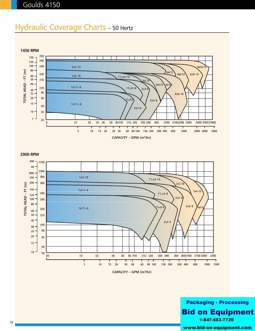
Hydraulic Coverage Charts – 50 Hertz
5 10 15 20 30 40 60 80 100 150 200 300 400 600
CAPACITY – GPM (m3/hr)
0 (1) (2) (3) (4) (6) (8) (10) (15) (20) (30) (40) (60) (100) (150) (200
1000 2000 3000 5000
(50)
(40)
(30)
(20)
(15)
(10)
(8)
(6)
(4)
(3)
(2)
150
120100
80
6050
40
3025
20
15
10
7
TOTA
L H
EAD
– F
T (m
)
)� (300) (500) (700) (1000)
1x11/ 2 -6
11/2 x3-6
2x3-6
3x4-8
2x3-811/2x3-81x11/2 -8
1x2-10
2x3-13
11/2 x3-102x3-10
3x4-10 4x4-10
4x6-10
3x4-134x6-13 6x8-13
8x10-15
5 10 15 20 30 40 60 80 100 150 200 300 400 600
CAPACITY – GPM (m3/hr)
(0) (1) (2) (4) (6) (8) (10) (15) (20) (30) (40) (60) (80
1000 1500
� )(100) (150) (200) (300)
(150)
(100)
(80)
(60)
(40)
(30)
(20)
(15)
(10)
(8)
(6)
(4)
(3)
500
40
300)
250
200
150
120100
80
6050
40
30
25
20
15
10
TOTA
L H
EAD
– F
T (m
)
1x11/2-6 11/2x3-6
2x3-6
3x4-8
2x3-811/2 x3-8
1x11/2 -8
1x2-1011/2 x3-10
2x3-10
3x4-10
4x4-10
1450 RPM
2900 RPM
Goulds 4150
11
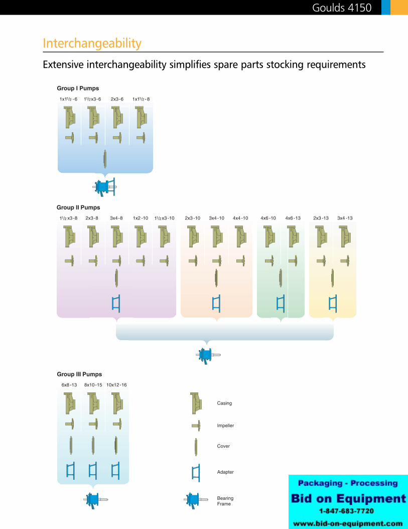
Interchangeability
Extensive interchangeability simplifies spare parts stocking requirements
Casing
Impeller
Cover
Adapter
BearingFrame
Form B4150 11/05© 2005 Goulds Pumps, Incorporated
A subsidiary of ITT Industries, Inc.
Visit our website at www.gouldspumps.com
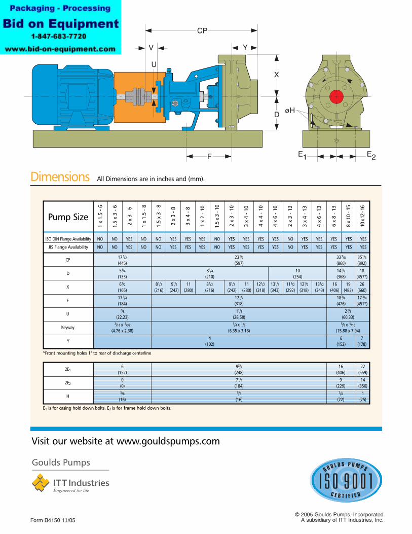
CP
F
YV
X
D
E1 E2
øH
U
Pump Size
1 x
1.5
- 6
1.5
x 3
- 6
2 x
3 - 6
1 x
1.5
- 8
1.5
x 3
- 8
2 x
3 - 8
3 x
4 - 8
1 x
2 - 1
0
1.5
x 3
- 10
2 x
3 - 1
0
3 x
4 - 1
0
4 x
4 - 1
0
4 x
6 - 1
0
2 x
3 - 1
3
3 x
4 - 1
3
4 x
6 - 1
3
6 x
8 - 1
3
8 x
10 -
15
ISO DIN Flange Availability NO NO YES NO NO YES YES YES NO YES YES YES YES NO YES YES YES YES YES
JIS Flange Availability NO NO YES NO NO YES YES YES NO YES YES YES YES NO YES YES YES YES YES
CP 171/2 231/2 337/8 351/8(445) (597) (860) (892)
D 51/4 81/4 10 141/2 18(133) (210) (254) (368) (457*)
X 61/2 81/2 91/2 11 81/2 91/2 11 121/2 131/2 111/2 121/2 131/2 16 19 26(165) (216) (242) (280) (216) (242) (280) (318) (343) (292) (318) (343) (406) (483) (660)
F 171/4 121/2 183/4 173/4(184) (318) (476) (451*)
U7/8 11/8 23/8
(22.23) (28.58) (60.33)
Keyway3/16 x 3/32 1/4 x 1/8 5/8 x 5/16
(4.76 x 2.38) (6.35 x 3.18) (15.88 x 7.94)
Y 4 6 7(102) (152) (178)
10 x
12 - 1
6
*Front mounting holes 1" to rear of discharge centerline
E1 is for casing hold down bolts. E2 is for frame hold down bolts.
Dimensions All Dimensions are in inches and (mm).
2E16 93/4 16 22
(152) (248) (406) (559)
2E20 71/4 9 14
(0) (184) (229) (356)
H5/8 5/8 7/8 1
(16) (16) (22) (25)