4/2001 vortex flowmeter operating instructions vfm 5090 (i) · if the dryness fraction is less than...
TRANSCRIPT

4/2001
Vortex flowmeter Installation and operating Instructions VFM 5090 (I)
P
1. Description
2. Installation in the pipeline
2.1 General 2.2 Sandwich type to DIN 19205 / ANSI 2.3 Flanged type to DIN 2501 / ANSI B16.52.4 Temperature and Pressure measureme2.4.1 Temperature measurement 2.4.2 Pressure measurement with built-in senso2.4.3 Pressure measurement by external means 3. Electrical connection
3.1 Installation location and cable diamete3.2 Connection to power 3.3 Outputs 3.3.1 Abbreviations 3.3.2 Current (analog) output I 3.3.3 Frequency (pulse) output F 3.3.4 Connection diagram for outputs � to � 4. Start-up
P 5. Operation of the signal converter
5.1 General 5.1.1 Starting up signal converter 5.1.2 Measurement mode 5.1.3 Programming or menu mode 5.1.4 Error handling 5.2 Operating elements 5.3 Program organization and programmi5.3.1 Menu levels 5.3.2 Programming chart 5.3.3 Description of keys 5.4 Programming and function of keys 5.5 Error Messages 5.5.1 Error Messages in Measurement mode 5.5.2 Error Messages in Programming mode 5.5.3 Other Error Messages 5.6 Plausibility Checks 5.7 Options available with VFM 5090(I) 5.7.1 METER TYPE 5.7.2 OUTPUT TYPE
Contents
art A System installation and Start-up 11
1-3 4
(SCH-40) 4 nts 4
4 r 5 5
5
r 5 5 6 6 6 6 7-8
8
0
art B Signal converter VFC 09 99 9 9 9 9 10
ng chart 11 11 12 13 14-15 16 16 17 17 17 18 18-19 20-24
6. Description of program functions 25 6.1 Numerical order description 25 6.1.1 Program function description 25-39 6.1.2 Program function description for AGA supported software 39 6.2 Functional order description 40 6.2.1 Physical units 40-41 6.2.2 Numerical format 42 6.2.3 Display 42 6.2.4 Flow range and meter size 43 6.2.5 Primary information 43 6.2.6 Application information 43 6.2.7 Internal Electronic Totalizer 43 6.2.8 Current (analog) output I 44 6.2.9 Frequency (pulse) output F 45-46 6.2.10 Languages of display text 46 6.2.11 Coding desired for entry into programming mode 46 6.2.12 Behaviour of outputs during programming 46
P
P
P
art C Functional checks and Trouble shooting hints
7. Functional checks 47 7.1 Primary head functional checks 47 7.1.1 Vortex Sensor 47 7.1.2 Temperature Sensor 47 7.2 Signal converter functional checks 47 7.2.1 Self diagnostics 47 7.2.2 Display check 48 7.2.3 Current output check 48 7.2.4 Frequency output check 488. Trouble shooting hints 48-49
art D VFM 5000(I)Ex
9. Description of the system 50 9.1 VFM 5090(I)Ex Earthing connections 50 9.2 Electrical connection 50 10. Process pressure and temperature 50 11. Replacement of the electronics in signal converter 50-51 12. Nameplates of VFM 5090(I)Ex 52
art E TECHNICAL DATA 53-76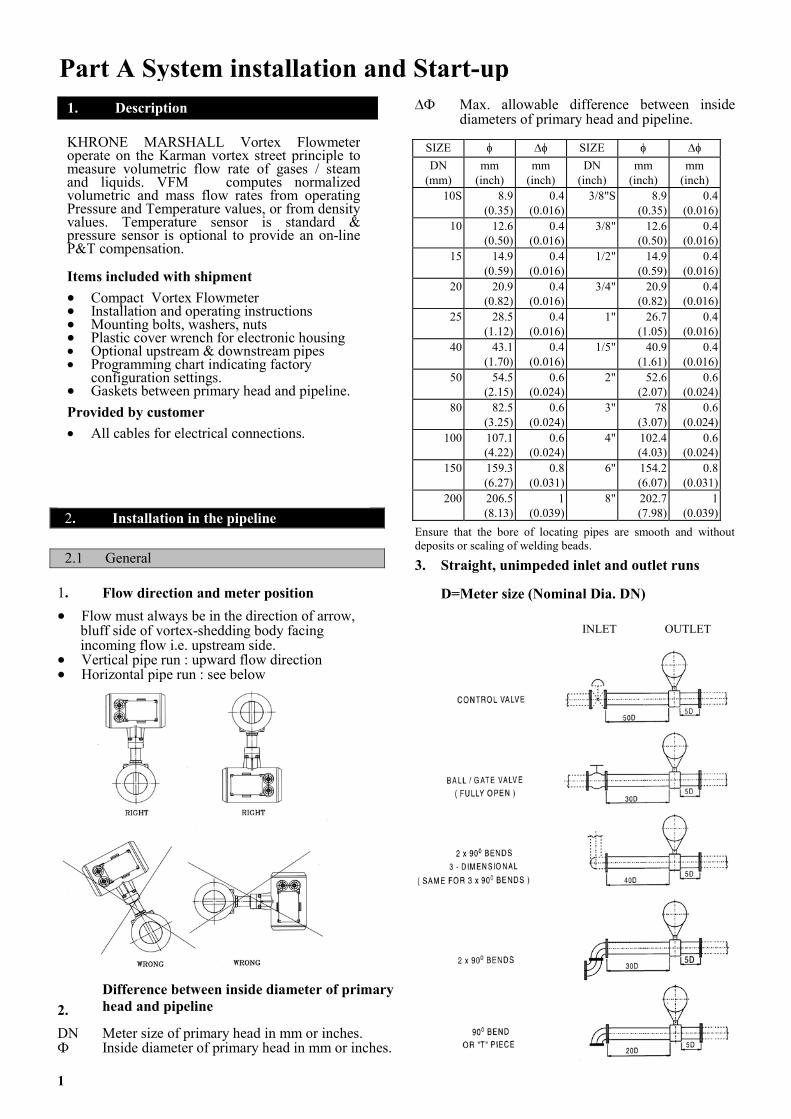
1�
�
�
2D�
P
1
art A System installation and Start-up
2. Installation in the pipeline
2.1 General
. Flow direction and meter position �
�
�
Flow must always be in the direction of arrow, bluff side of vortex-shedding body facing incoming flow i.e. upstream side. Vertical pipe run : upward flow direction Horizontal pipe run : see below
.
Difference between inside diameter of primary head and pipeline
N
Meter size of primary head in mm or inches. Inside diameter of primary head in mm or inches.
�� Max. allowable difference between inside
diameters of primary head and pipeline. 1. Description
KHRONE MARSHALL Vortex Flowmeteroperate on the Karman vortex street principle tomeasure volumetric flow rate of gases / steamand liquids. VFM computes normalizedvolumetric and mass flow rates from operatingPressure and Temperature values, or from densityvalues. Temperature sensor is standard &pressure sensor is optional to provide an on-line P&T compensation.
Items included with shipment ��
��
��
��
��
Compact Vortex Flowmeter Installation and operating instructions Mounting bolts, washers, nuts Plastic cover wrench for electronic housing
�� Optional upstream & downstream pipes �� Programming chart indicating factory
configuration settings. Gaskets between primary head and pipeline.
Provided by customer �� All cables for electrical connections.
SIZE � �� SIZE � �� DN
(mm) mm
(inch) mm
(inch) DN
(inch) mm
(inch) mm
(inch) 10S 8.9
(0.35)0.4
(0.016) 3/8"S 8.9
(0.35)0.4
(0.016)10 12.6
(0.50)0.4
(0.016) 3/8" 12.6
(0.50)0.4
(0.016)15 14.9
(0.59)0.4
(0.016) 1/2" 14.9
(0.59)0.4
(0.016)20 20.9
(0.82)0.4
(0.016) 3/4" 20.9
(0.82)0.4
(0.016)25 28.5
(1.12)0.4
(0.016) 1" 26.7
(1.05)0.4
(0.016)40 43.1
(1.70)0.4
(0.016) 1/5" 40.9
(1.61)0.4
(0.016)50 54.5
(2.15)0.6
(0.024) 2" 52.6
(2.07)0.6
(0.024)80 82.5
(3.25)0.6
(0.024) 3" 78
(3.07)0.6
(0.024)100 107.1
(4.22)0.6
(0.024) 4" 102.4
(4.03)0.6
(0.024)150 159.3
(6.27)0.8
(0.031) 6" 154.2
(6.07)0.8
(0.031)200 206.5
(8.13)1
(0.039) 8" 202.7
(7.98)1
(0.039)Ensure that the bore of locating pipes are smooth and without deposits or scaling of welding beads.
3. Straight, unimpeded inlet and outlet runs
D=Meter size (Nominal Dia. DN) INLET OUTLET
INLET OUTLET
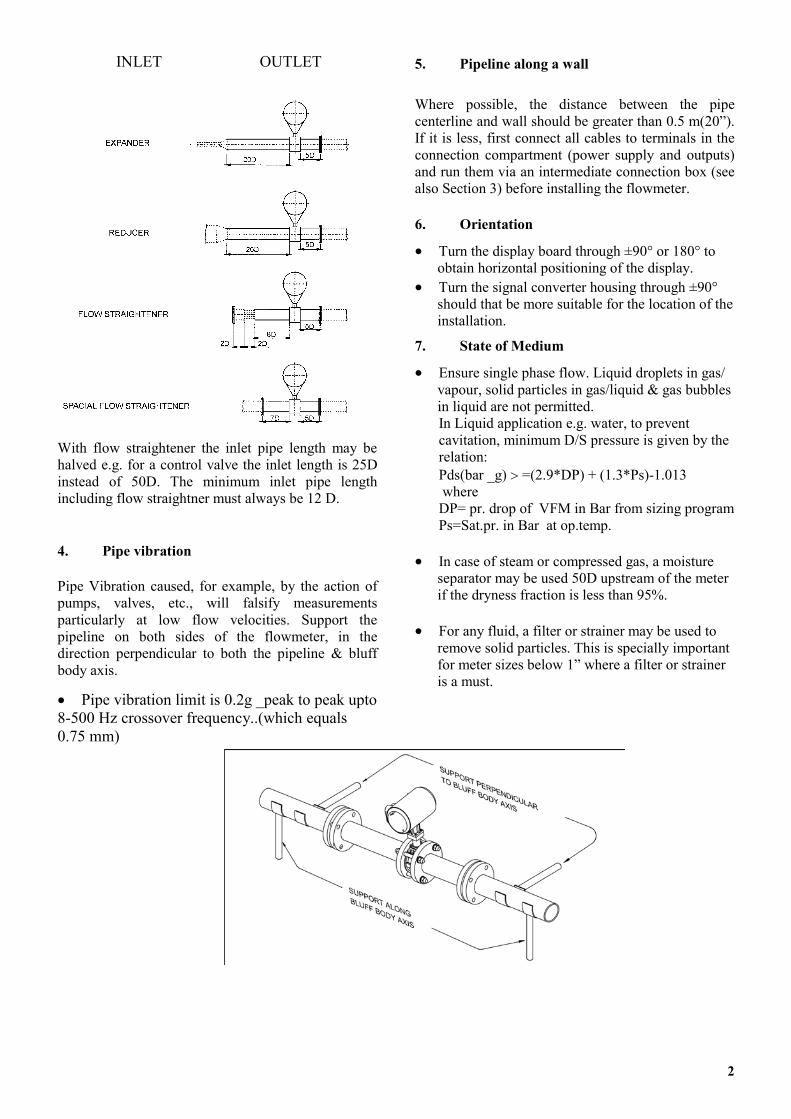
With flow straightener the inlet pipe length may be halved e.g. for a control valve the inlet length is 25D instead of 50D. The minimum inlet pipe length including flow straightner must always be 12 D.
4. Pipe vibration
Pipe Vibration caused, for example, by the action of pumps, valves, etc., will falsify measurements particularly at low flow velocities. Support the pipeline on both sides of the flowmeter, in the direction perpendicular to both the pipeline & bluff body axis.
�� Pipe vibration limit is 0.2g _peak to peak upto 8-500 Hz crossover frequency..(which equals 0.75 mm)
5. Pipeline along a wall
Where possible, the distance between the pipe centerline and wall should be greater than 0.5 m(20”). If it is less, first connect all cables to terminals in the connection compartment (power supply and outputs) and run them via an intermediate connection box (see also Section 3) before installing the flowmeter.
6. Orientation
Turn the display board through ±90° or 180° to obtain horizontal positioning of the display.
��
��
��
��
��
Turn the signal converter housing through ±90° should that be more suitable for the location of the installation.
7. State of Medium
Ensure single phase flow. Liquid droplets in gas/ vapour, solid particles in gas/liquid & gas bubbles in liquid are not permitted. In Liquid application e.g. water, to prevent cavitation, minimum D/S pressure is given by the relation: Pds(bar _g) � =(2.9*DP) + (1.3*Ps)-1.013 where DP= pr. drop of VFM in Bar from sizing program Ps=Sat.pr. in Bar at op.temp.
In case of steam or compressed gas, a moisture separator may be used 50D upstream of the meter if the dryness fraction is less than 95%.
For any fluid, a filter or strainer may be used to remove solid particles. This is specially important for meter sizes below 1” where a filter or strainer is a must.
2

Sandwich Version
3
Flanged Version

2.2 Sandwich type to DIN19205 / ANSI ��
��
Meter sizes DN 25, 40, 50, 80,100 and 150 (1”to 6”) Pipe flanges (Pressure ratings to DIN :- DN25/PN40, 100; DN40/PN40, 100; DN50/PN40, 64, 100; DN80/PN40, 64, 100; DN100/PN16, 40, 64 and DN 150 / PN16, 40 to ANSI : 1” to 6”/ # 150, 300 SORF)
��
��
��
Gaskets inside diameter must be greater than the inside diameter � of the primary head. e.g. use flat gaskets to DIN 2690. Gaskets must not project into the effective pipe cross sectional area. Bolts, nuts and washers are supplied. Check flange connections for leak-tightness after flowmeter installation.
2.3 Flanged type to DIN 2501/ANSI B 16.5(SCH40)
Meter sizes DN 10S, 10, 15, 20, 25, 40, 50, 80 100, 150 and 200 (3/8”S to 8”)
��
�� Pipe flanges to DIN : DN 25/PN 40, 100; DN 40/PN 40, 100; DN 50/PN 40, 64, 100; DN 80/PN 40, 64, 100; DN 100/PN 16, 40, 64; DN 150/PN 16, 40; DN 200/PN 10, 16 and to ANSI : 1/2” to 8” / # 150, 300 SORF)
Gaskets are supplied by us with flanged units.
Center the flowmeter by sight. ��
�� Check flange connections for leak-tightness after flowmeter installation.
2.4 Temperature and pressure measurements 2.4.1 Temperature measurement
Installation in Vertical Pipe Run
VFM 5090(I) is always supplied with a temperature sensor. This sensor is RTD (PT1000 type) and is located within the Vortex bluff body. See figure given for location of Temperature sensor. This sensor provides an accurate measurement of temperature of the medium at the vortex sensor.
Flowmeter will continuously measure medium temperature -
To display medium temperature ��
��
��
To provide on-line T compensation for mass and normalized flow computations. To monitor whether the medium temperature remains within the user specified operating temperature limits.
Installation in Horizontal Pipe Run
Assembly Diagram of Sandwich Units
4

VFM 5090(I) may be supplied with an optional pressure sensor. This sensor is typically a strain gauge type and located in the primary assembly as shown in the figure below. Thus the sensor also provides an accurate measurement of pressure of the process fluid.
Flowmeter will continuously measure medium pressure - ��
��
��
To display the medium pressure value To provide an on-line P&T compensation along with T sensor for mass and normalized volumetric flow computation. To monitor whether the medium pressure is within the user specified operating pressure limits.
To determine the pressure of the medium (e.g. to feed the pressure value in VFM for an off-line P&T compensation for mass or normalized flow computations), suitable measuring point must be provided near the flowmeter.
Location upstream of flowmeter
Min. distance : 20*DN (DN = meter size)
Location downstream of flowmeter
Min. distance : 5*DN (DN = meter size)
Allowance must be made for the pressure drop in the flowmeter as correction value for operating conditions prevailing upstream of the flowmeter.
3. Electrical connection
3.1 Installation location and cable diameter
Location
��
��
��
��
��
��
��
��
��
��
��
Do not expose the compact flowmeter to direct sunlight. Install a sunshade if necessary. Do not expose to intense vibration. If necessary support the pipeline to the left & right of the flow meter.
The rotating design of the housing makes it easier to connect the two cables for power and outputs to the terminals in the rear terminal box.
2.4.2 Pressure measurement with built-in sensor
Cable diameter
To conform to protection category requirements, observe the following recommendations
Cable diameter : 8 to 13 mm (0.31” to 0.51”) Enlarge the inside diameter of the Screwed conduit entry by removing the appropriate onion ring(s) from the seal,only if cables have extremely tight fit. Fit blanking plug PG 16 and apply sealant to unused cable entries. Do not kink cables at conduit entries. Provide water drip point (U bend in cable).
Conduit Installation, general wiring considerations
When electrical codes require conduit, it must be installed in such a manner that the meter connection compartment remains dry at all times. Power and output wiring should be run in a separate conduit. Use twisted pair for output wiring.
WARNING Power wiring should utilize a grounded conductor to avoid possible shock hazard and damage to component parts.
2.4.3 Pressure measurement by external means 3.2 Connection to power
Note information given on the instrument name plate (voltage, frequency)!
��
��
��
��
��
��
Electrical connection in conformity with VDE 0100 “Regulations governing heavy-current installations with rated voltages up to 1000V” or equivalent national standard. The PE protective ground conductor for supply power must be connected to the separate U-clamp terminal in the terminal box of the signal converter. Do not cross or loop cables in the terminal box of the signal converter. Use separate PG or NPT screwed conduit entries for power and output cables. Ensure that the screw thread of the round cover on the terminal box is well greased at all times. Connection to power, VFM 5090(I)
5
6
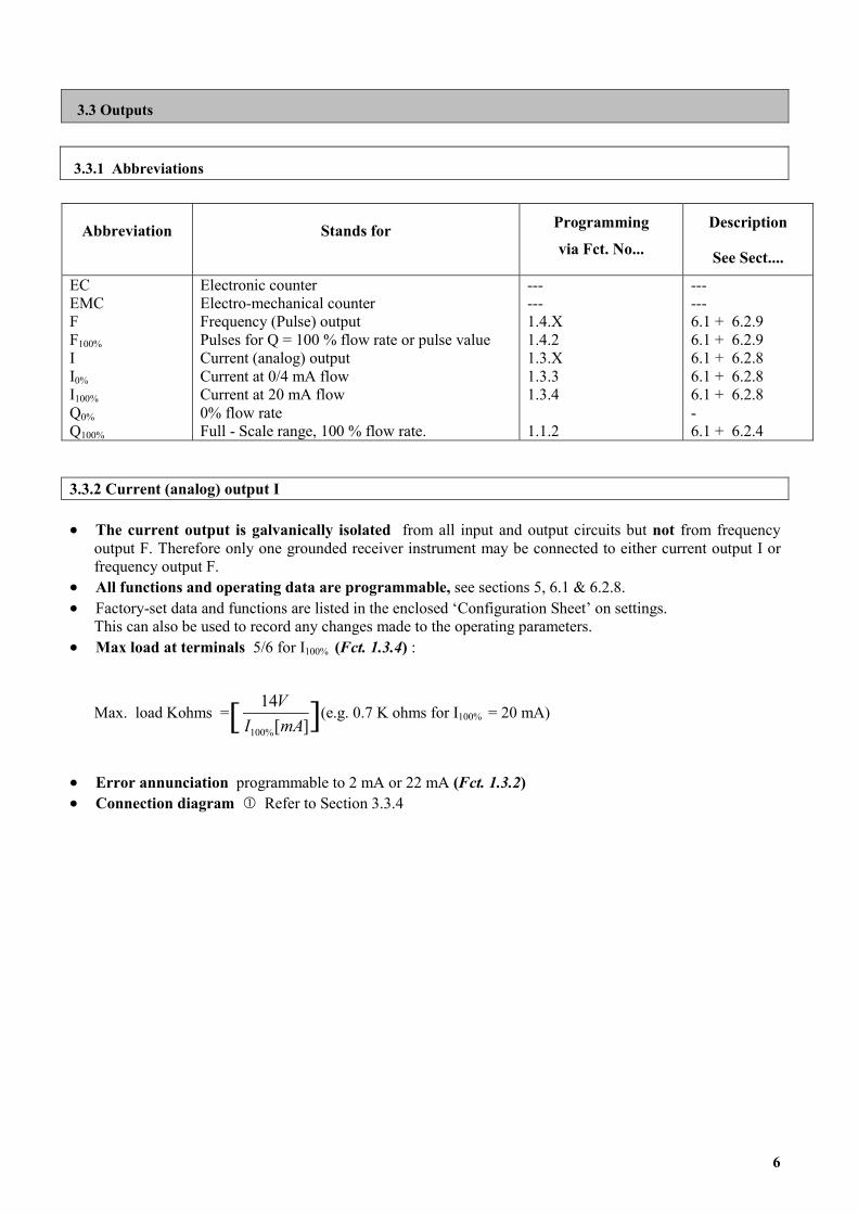
3.3 Outputs
3.3.1 Abbreviations
Abbreviation Stands for Programming
via Fct. No...
Description
See Sect....
EC EMC F F100% I I0% I100% Q0% Q100%
Electronic counter Electro-mechanical counter Frequency (Pulse) output Pulses for Q = 100 % flow rate or pulse value Current (analog) output Current at 0/4 mA flow Current at 20 mA flow 0% flow rate Full - Scale range, 100 % flow rate.
--- --- 1.4.X 1.4.2 1.3.X 1.3.3 1.3.4 1.1.2
--- --- 6.1 + 6.2.9 6.1 + 6.2.9 6.1 + 6.2.8 6.1 + 6.2.8 6.1 + 6.2.8 - 6.1 + 6.2.4
3.3.2 Current (analog) output I
The current output is galvanically isolated from all input and output circuits but not from frequency output F. Therefore only one grounded receiver instrument may be connected to either current output I or frequency output F.
��
��
��
��
All functions and operating data are programmable, see sections 5, 6.1 & 6.2.8. Factory-set data and functions are listed in the enclosed ‘Configuration Sheet’ on settings. This can also be used to record any changes made to the operating parameters. Max load at terminals 5/6 for I100% (Fct. 1.3.4) :
Max. load Kohms = ][
14
%100 mAV
(e.g. 0.7 K ohms for I100% = 20 mA) [ ]I
Error annunciation programmable to 2 mA or 22 mA (Fct. 1.3.2) ��
�� Connection diagram � Refer to Section 3.3.4

3.3.3 Frequency (pulse) output F
The frequency output is galvanically isolated from all input and output circuits but not from current output I. Therefore only one grounded receiver instrument may be connected to either frequency output F or current output I.
��
��
��
��
��
��
All functions and operating data are programmable, see Section 5, 6.1 & 6.2.9. Factory - set data and functions are listed in the enclosed report on settings. This can also be used to record any changes made to the operating parameters. Active frequency output for electromechanical totalizers EMC (terminals 4.1/4.2) or for electronic totalizers EC (terminals 4.1/4.2 or 4/4.1/4.2), 10 to 36000000 pulses/hr (0.0028 to 10000 Hz), amplitude max. 30 V, selectable pulse widths and load rating see below. Passive frequency output, open collector for connection of active electronic counters EC or switchgear, input voltage 5 to 30V, load current max. 100 mA, Ri = 100 ohms, selectable pulse widths see below. Pulse width (Fct. 1.4.3) as a factor of frequency f (pulse rate) and maximum permissible load for active output (term. 4.1/4.2 or 4/4.1/4.2), see also Sect. 6.2.9.
Pulse width Frequency f = F100% Load rating of active output
Load current Load 500 ms 0.0028 Hz < f
� 1 Hz < 150 mA �160 Ohm
200 ms 0.0028 Hz < f �
2 Hz < 150 mA �160 Ohm
100 ms 0.0028 Hz < f �
3 Hz < 150 mA �160 Ohm
100 ms 3 Hz < f �
5 Hz < 60 mA �400 Ohm
50 ms 0.0028 Hz < f �
5 Hz < 150 mA �160 Ohm
50 ms 5 Hz < f �
10 Hz < 60 mA �400 Ohm
30 ms 0.0028 Hz < f �
6 Hz < 150 mA �160 Ohm
30 ms 6 Hz < f �
10 Hz < 80 mA �300 Ohm
Pulse duty cycle 1:1* 10 Hz < f �
1000 Hz < 25 mA �1000 Ohm
160 µs* 1000 Hz < f �
2547 Hz < 25 mA �1000 Ohm
50 µs* 2547 Hz < f �
10000 Hz < 25 mA �1000 Ohm
* fixed pulse width, independent of programming in Fct. 1.4.3 Refer connection diagrams �, � and �. Refer to Section 3.3.4 ��
��
Output characteristics 3.3.4 Connection diagram for outputs � to �
Current output I: Diagrams I1 in Section 6.2.8
7

8
3. Frequency output F: Diagram F1 in Section 6.2.9 R1 & R2 when electronic counter is connected to terminals 4/4.1/4.2 connection diagram � R1 = 1 Kohm , 1W R2 needed only for totalizer with input voltage Umax < 30 Volts.
Umax 24 V 12 V 5 V R2 3.9 Kohm 680 ohm 180 ohm
4. Start-up
Check that the system has been correctly installed as described in Sect. 1, 2 and 3. ��
��
��
��
��
��
Before initial start-up check that the following details on the nameplate agree with the data specified in the report of settings for the signal converter. If not, reprogramming will be necessary. Meter size Fct. 3.1.1 Sect. 6.1, 6.2.5. K-Factor Fct. 3.1.2 Sect. 6.1, 6.2.5.
The flowmeter is ready for service 15 minutes (waiting time) after switching on the power source. Increase flow velocity slowly and steadily.
Avoid abrupt changes in pressure in the pipeline.
If the process product is steam, condensate may form initially and cause faulty measurements when the system is started up for the first time.
When powered, the signal converter normally operates in the measurement mode. The power-on sequence to measurement mode is as follows : ‘TEST’ is displayed for approx. 3 seconds followed by ‘VFM 5090’ the instrument type followed by ‘Ver x.xx’ the software version of the instrument. Then instrument operates in measurement mode where it displays the parameter being measured or ‘FATAL ERROR ’ if there are one or more critical errors detected (For description on errors refer Sect 5.5)
9
5
5
Wmfpai
5
Iacms
5
Adv
�
�
5
Cas
Ii
Part B Signal Converter VFC 090
5. Operation of the signal converter
.1 General
.1.1 Starting up signal converter
hen power is switched ON to signal convertor it displays TEST, VFM 5090 & Ver x.xx and then goes to easurement mode. In this initial sequence VFM 5090(I) carries out self diagnostics to check its own
unctional elements and loads the configuration data from non-volatile memory. If any error(s) are detected in ower-ON diagnostics, the converter displays FATAL.ERROR since instrument has critical error(s) and is not ble to carry out normal measurements. If no start-up errors are detected the first measured parameter displayed s the one being displayed when power supply was removed last time.
.1.2 Measurement Mode
n measurement mode, the parameters that the converter measures/computes are shown on the display in the ppropriate units. (See Sect. 5.2 for display details). As per the configuration, display can be either in non-yclic/cyclic mode. In non cyclic mode of display, use � key to see the next parameter on display. In cyclic ode display shows all the parameters one after another, wherein each parameter is displayed for about 6
econds.
.1.3 Programming or menu mode
ll the configurations/settings/test functions are grouped in the form of menu tree structure (see Sect. 5.3.1 for etails) and are accessible in the programming mode. Operator can view or alter the present settings and data alues by the use of functions available in this mode.
All changes made in the programming mode are stored temporarily until the operator quits to the measurement mode and responds YES to an ‘UPDATE’ prompt. Only then the new changes are saved in non-volatile memory and have appropriate effect on the operation of signal converter.
�
� Even in the programming mode the converter “keeps working” as per present configuration. Simply stated, the converter continues to measure (flow rate, totalizing of flow, P, T etc.) and control outputs (current and frequency outputs) while in the programming mode.
.1.4 Error handling
onverter can detect errors during power-on diagnostics as well as when in normal measurement mode. Errors re divided into two main categories viz. fatal errors and non-fatal errors. Fatal errors cause measurement to top since they are serious in nature. Non-fatal errors do not affect functionality of the converter.
f one or more errors are present, display (in the measurement mode) starts blinking. If programmed so, error nformation is shown on display, interleaved between the display of two parameters.

5.2 Operating elements
CAUTION To avoid damage to electronics, be certain that the area around the meter is dry before removing the electronics compartment cover.
The operating elements are accessible after removing the cover of the electronics section using the special wrench. CAUTION Do not damage screw thread, never allow dirt to accumulate, and make sure it is well greased at all times. �
�
�
Display, 1st line Display, 2nd line Display, 3rd line
Cursor symbols described below qv
qm � T P u
Volumetric flow rate Mass flow rate Totalizer value Measured / Set temperature value Measured / Set pressure value Velocity of medium
� Keys for programming the Signal Converter, refer to Sect. 5.4 for the functions of keys.
�
6�
Magnetic Sensors to program the converter by means of a hand-held bar magnet without having to open the housing, refer to Sect. 6.3. Function of sensors is same as keys �. Hold the bar magnet by the cap. Apply other end of the magnet (north pole) to the glass pane above the magnetic sensors. Sensor or key response is acknowledged by symbols appearing in 1st line of display. xxx on the display is used to describe the type of the meter. It can be : 1. AGA - Natural Gas Meter (AGA) 2. FAD - Free Air Delivery 3. HM - Heat Meter 4. NHM - Net Heat Meter 5. STD - Standard
10
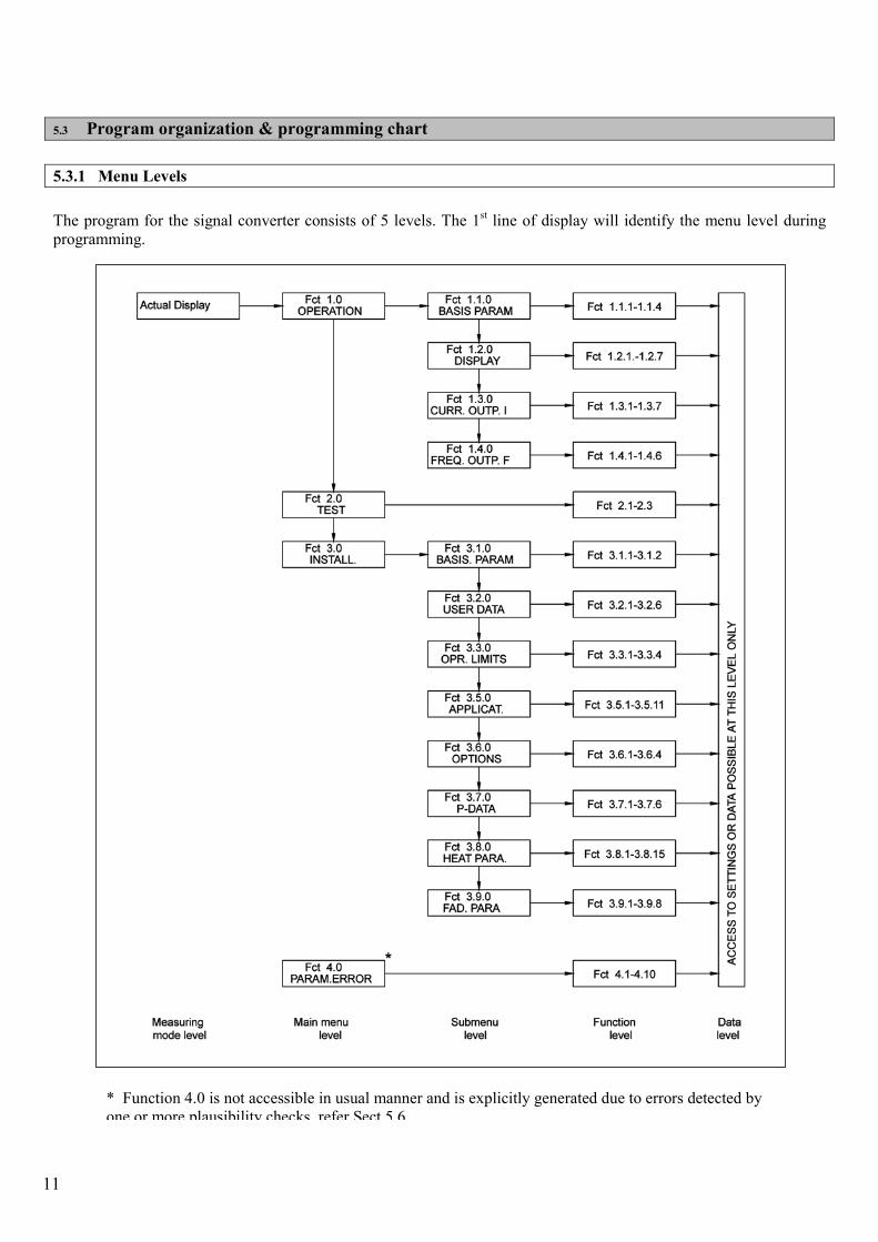
5.3 Program organization & programming chart
5.3.1 Menu Levels
The program for the signal converter consists of 5 levels. The 1st line of display will identify the menu level during programming.
* Function 4.0 is not accessible in usual manner and is explicitly generated due to errors detected by one or more plausibility checks, refer Sect 5.6
11

5.3.2 Programming chart
Error Msg DISPLAY Fct 1.2.7 FUNCTIONSFct 3.2.2 as YES
TESTFct 2.0
Fct 3.0INSTALL.
Fct 4.0PARAM.ERROR
Duringplausibilitycorrections
NOUPDATE NO?
PARAMETERNEXT MEASURED
Next Error Msg---
E
n Err ---
settings not
Saved YES checks OK?
NO??
Plausibility
Settings changed?
? E
YES
NO
E
YES
ENTRY.CODE.1
savedsettings
Fct 4.10Fct 4.1 TO
EE
FUNCTIONSActual 4.X
FUNCTIONSOPR. LIMITS Fct 3.3.4
Fct 3.5.11Fct 3.5.1 TO
Fct 3.6.4Fct 3.6.1 TO
Fct 3.7.1 TO
Fct 3.8.15Fct 3.8.1 TO
Fct 3.9.8Fct 3.9.1 TO
Fct 3.7.6P-DATA
Fct 3.9.0FAD. PARA
HEAT PARA.Fct 3.8.0
E
E
E
Fct 3.7.0
OPTIONS
APPLICAT.
Fct 3.6.0
Fct 3.5.0
E
E
E
FUNCTIONS
E
E
E
FUNCTIONSActual 3.9.X
FUNCTIONSActual 3.8.X
E
E
E
Actual 3.7.X
FUNCTIONSActual 3.6.X
FUNCTIONSActual 3.5.X
Fct 1.3.7Fct 1.3.1 TO
Fct 1.4.6Fct 1.4.1 TO
Fct 2.1 TO
Fct 3.1.2Fct 3.1.1 TO
Fct 3.2.6Fct 3.2.1 TO
Fct 3.3.1 TO
Fct 2.3E
Fct 3.3.0
USER DATAFct 3.2.0
Fct 3.1.0BASIS. PARAM
E E
E
CURR. OUTP. IFct 1.3.0
FREQ. OUTP. FFct 1.4.0
E
E
E
FUNCTIONS
E
E
E
Actual 3.3.X
FUNCTIONSActual 3.2.X
FUNCTIONSActual 3.1.X
E
E
E
Actual 2.X
FUNCTIONSActual 1.4.X
FUNCTIONSActual 1.3.X
OPERATIONFct 1.0
PARAMETERMEASURED
--- n Err ---
CODE 1(9 keys)
Fct 3.2.2 as NO
Password
ENTRY.CODE.1Fct 1.1.1 TO
Fct 1.1.4
Fct 1.2.1 TOFct 1.2.0
Fct 1.1.0BASIS PARAM
E E E
Actual 1.2.X
FUNCTIONSActual 1.1.X
12

13
5.3.3 Description of keys � Measuring mode level � Main menu level � Submenu level � Function level � Data level � display measured
parameters /error messages
� �
Go to main menu Enter main menu displayed
� �
Go to submenu Enter submenu displayed
� Go to Function Units/Options
�
Go to next proposE Enter programming mode
E Return to measuring mode level
E Return to main menu level
� Enter/execute function displayed. Then continue as under � data level �
E Return to submenu level or main menu level
E Temporarily saveproposal then with further data any, or return function level
Important 1. All changes made in programming mode are stored temporarily and do not affect
operation of the signal converter until operator leaves menu mode and responds with UPDATE YES. Exceptions: all 2.X test functions.
2. Main menu level 4.0 PARAM.ERROR is automatically created if the plausibility checks on the new configuration detects invalid values entered. (See section 5.6 for details)
3. VFM 5090(I) continues to function even when in programming mode.
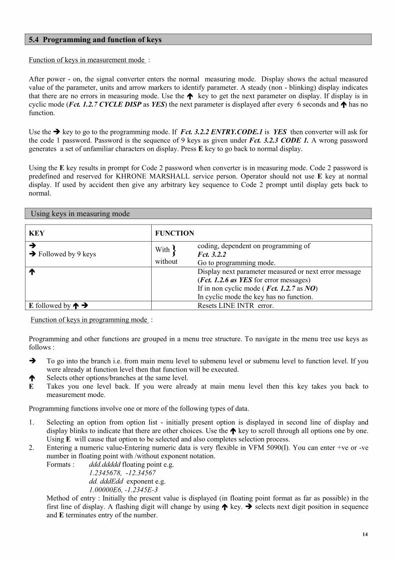
5.4 Programming and function of keys
Function of keys in measurement mode :
After power - on, the signal converter enters the normal measuring mode. Display shows the actual measured value of the parameter, units and arrow markers to identify parameter. A steady (non - blinking) display indicates that there are no errors in measuring mode. Use the � key to get the next parameter on display. If display is in cyclic mode (Fct. 1.2.7 CYCLE DISP as YES) the next parameter is displayed after every 6 seconds and � has no function.
Use the � key to go to the programming mode. If Fct. 3.2.2 ENTRY.CODE.1 is YES then converter will ask for the code 1 password. Password is the sequence of 9 keys as given under Fct. 3.2.3 CODE 1. A wrong password generates a set of unfamiliar characters on display. Press E key to go back to normal display.
Using the E key results in prompt for Code 2 password when converter is in measuring mode. Code 2 password is predefined and reserved for KHRONE MARSHALL service person. Operator should not use E key at normal display. If used by accident then give any arbitrary key sequence to Code 2 prompt until display gets back to normal.
Using keys in measuring mode
KEY FUNCTION
� � Followed by 9 keys With }
without
coding, dependent on programming of Fct. 3.2.2 Go to programming mode.
� Display next parameter measured or next error message (Fct. 1.2.6 as YES for error messages) If in non cyclic mode ( Fct. 1.2.7 as NO) In cyclic mode the key has no function.
E followed by � � Resets LINE INTR error.
Function of keys in programming mode :
Programming and other functions are grouped in a menu tree structure. To navigate in the menu tree use keys as follows :
� To go into the branch i.e. from main menu level to submenu level or submenu level to function level. If you were already at function level then that function will be executed.
� Selects other options/branches at the same level. E Takes you one level back. If you were already at main menu level then this key takes you back to
measurement mode.
Programming functions involve one or more of the following types of data.
1. Selecting an option from option list - initially present option is displayed in second line of display and display blinks to indicate that there are other choices. Use the � key to scroll through all options one by one. Using E will cause that option to be selected and also completes selection process.
2. Entering a numeric value-Entering numeric data is very flexible in VFM 5090(I). You can enter +ve or -ve number in floating point with /without exponent notation.
Formats : ddd.ddddd floating point e.g. 1.2345678, -12.34567 dd. dddEdd exponent e.g. 1.00000E6, -1.2345E-3
Method of entry : Initially the present value is displayed (in floating point format as far as possible) in the first line of display. A flashing digit will change by using � key. � selects next digit position in sequence and E terminates entry of the number.
14
Notes
a) When you use � to move cursor and all digits start flashing then it means that you are at the decimal point position. At this time use of � moves decimal point across the number.
b) Usually digits cycle through 0-9 values. At certain relevant position they cycle through 0, 1, 2, . . . 9, -/E for -ve number or exponent notation.
c) When you enter a value beyond its limit then you get message dddd.dddd (MIN.VALUE) or dddd.dddd (MAX.VALUE). Press E after you have noted limit and then correct value to be in valid limits.
d) If you don’t want to change value press E at the beginning itself!
3. Entering string (alphanumeric value) - This type of data input is required by a few functions. Present string is displayed in the 2nd line and as usual 1st column blinks. Use :
� to scroll through characters 0 - 9, A - Z, a - z and some other punctuation characters. � Change flashing (cursor) position E Terminate data entry.
Note :
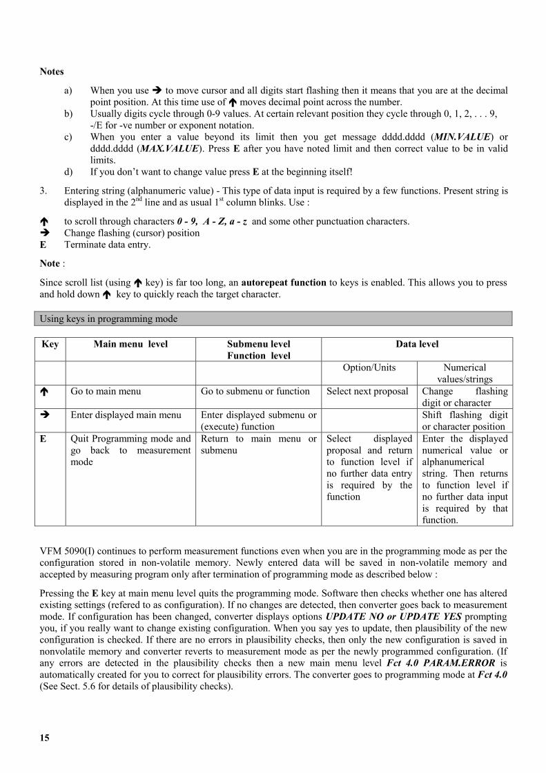
Since scroll list (using � key) is far too long, an autorepeat function to keys is enabled. This allows you to press and hold down � key to quickly reach the target character. Using keys in programming mode Key Main menu level Submenu level
Function level Data level
Option/Units Numerical values/strings
� Go to main menu Go to submenu or function Select next proposal Change flashing digit or character
� Enter displayed main menu Enter displayed submenu or (execute) function
Shift flashing digit or character position
E Quit Programming mode and go back to measurement mode
Return to main menu or submenu
Select displayed proposal and return to function level if no further data entry is required by the function
Enter the displayed numerical value or alphanumerical string. Then returns to function level if no further data input is required by that function.
VFM 5090(I) continues to perform measurement functions even when you are in the programming mode as per the configuration stored in non-volatile memory. Newly entered data will be saved in non-volatile memory and accepted by measuring program only after termination of programming mode as described below :
Pressing the E key at main menu level quits the programming mode. Software then checks whether one has altered existing settings (refered to as configuration). If no changes are detected, then converter goes back to measurement mode. If configuration has been changed, converter displays options UPDATE NO or UPDATE YES prompting you, if you really want to change existing configuration. When you say yes to update, then plausibility of the new configuration is checked. If there are no errors in plausibility checks, then only the new configuration is saved in nonvolatile memory and converter reverts to measurement mode as per the newly programmed configuration. (If any errors are detected in the plausibility checks then a new main menu level Fct 4.0 PARAM.ERROR is automatically created for you to correct for plausibility errors. The converter goes to programming mode at Fct 4.0 (See Sect. 5.6 for details of plausibility checks).
15
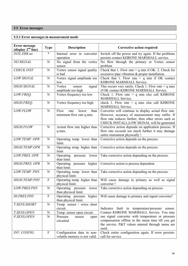
5.5 Error messages 5.5.1 Error messages in measurement mode Error message (display 2nd line) Type Description Corrective action required
INTL.ERR.nn * Internal error in converter operation
Switch off the power and try again. If the problems persists contact KHRONE MARSHALL service.
NO SIGNAL N No signal from the vortex sensor
No flow through the primary or Vortex sensor problem
CHECK INST N Vortex sensor signal quality is bad
Check that 1. Flow rate > q min if OK. 2. Check for excessive pipe vibration & proper installation.
LOW SIGNAL N Vortex signal amplitude too low.
Check that 1. Flow rate > q min if OK contact KHRONE MARSHALL Service.
HIGH SIGNAL N Vortex sensor signal amplitude too high
This occurs very rarely. Check 1. Flow rate < q max if OK contact KHRONE MARSHALL Service.
LOW.FREQ. N Vortex frequency too low Check 1. Flow rate > q min else call KHRONE MARSHALL Service.
HIGH.FREQ. N Vortex frequency too high check 1. Flow rate < q max else call KHRONE MARSHALL Service.
LOW.FLOW N Flow rate lower than minimum flow rate q min.
Converter will continue to display actual flow rate. However, accuracy of measurement may suffer. If flow rate reduces further, then other errors such as CHECK INSTALL,LOW SIGNAL will be generated
HIGH.FLOW N Actual flow rate higher than q max.
Corrective action depends on application process. If flow rate exceeds too much further it may damage entire instrument physically !
LOW.TEMP. OPR N Operating temp. lower than limit.
Corrective action depends on the process.
HIGH.TEMP.OPR N Operating temp. higher than limit
Corrective action depends on the process.
LOW.PRES. OPR N Operating pressure lower than limit.
Take corrective action depending on the process.
HIGH.PRES. OPR N Operating pressure higher than limit.
Corrective action is process dependent.
LOW.TEMP. PHY. N Operating temp. lower than physical limit.
Take corrective action depending on the process.
HIGH.TEMP.PHY F Operating temp. higher than physical limit.
Will cause damage to primary as well as signal converter !
LOW.PRES.PHY. N Operating pressure lower than physical limit.
Take corrective action depending on process.
HI.PRES.PHY F Operating pressure higher than physical limit.
Will cause damage to primary and signal converter!
T.SENS.SHORT N Temp. sensor / wires short circuit.
T.SENS.OPEN N Temp. sensor open circuit. P.SENS.OPEN N Pressure sensor open
circuited
Indicates fault in temperature/pressure sensor. Contact KHRONE MARSHALL Service. You may use signal converter with temperature or pressure compensation offline in the mean time till you get the service. P&T values entered through menu are used.
INV. CONFIG F Configuration data in non-volatile memory is not valid.
Check entire configuration again. If error persists-call for service
16
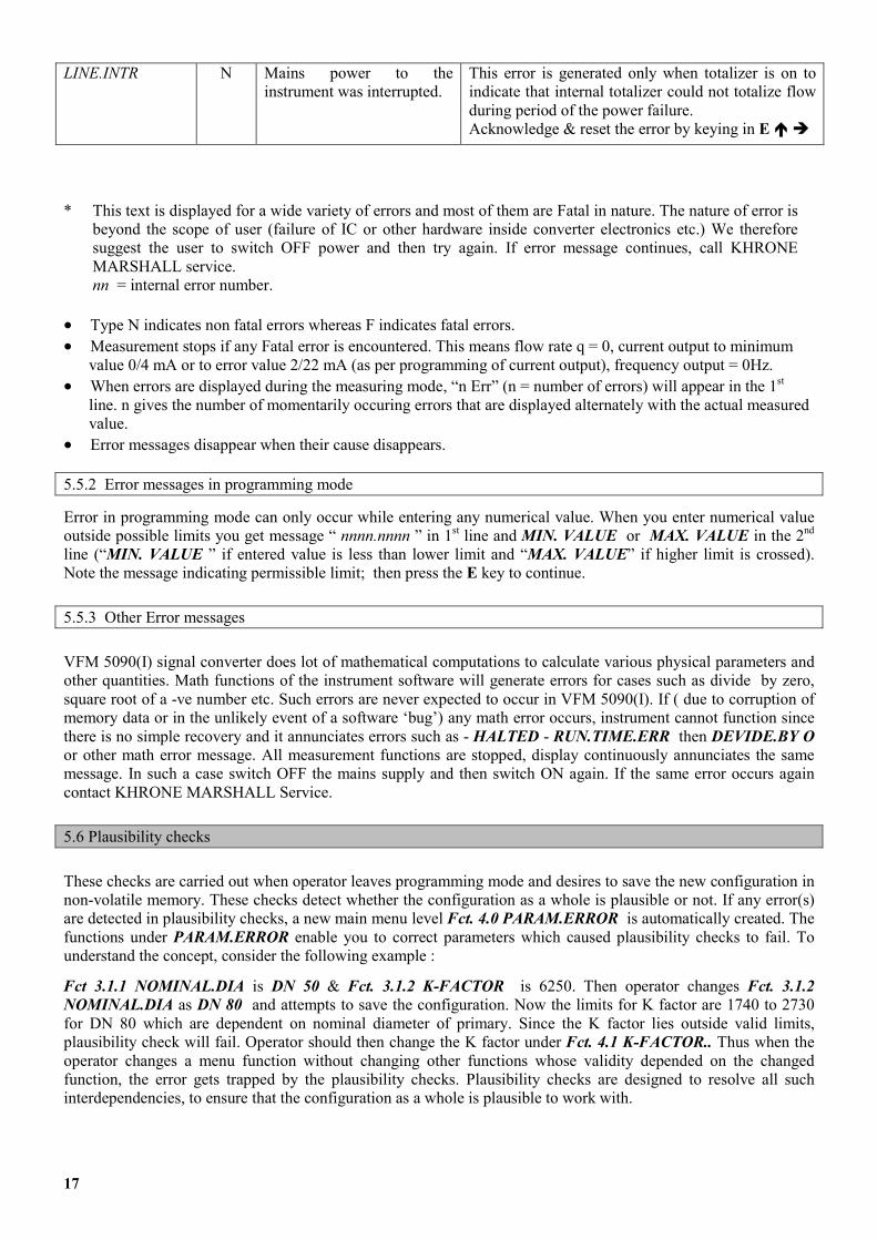
LINE.INTR N Mains power to the instrument was interrupted.
This error is generated only when totalizer is on to indicate that internal totalizer could not totalize flow during period of the power failure. Acknowledge & reset the error by keying in E � �
* This text is displayed for a wide variety of errors and most of them are Fatal in nature. The nature of error is
beyond the scope of user (failure of IC or other hardware inside converter electronics etc.) We therefore suggest the user to switch OFF power and then try again. If error message continues, call KHRONE MARSHALL service. nn = internal error number.
Type N indicates non fatal errors whereas F indicates fatal errors. ��
��
��
��
Measurement stops if any Fatal error is encountered. This means flow rate q = 0, current output to minimum value 0/4 mA or to error value 2/22 mA (as per programming of current output), frequency output = 0Hz. When errors are displayed during the measuring mode, “n Err” (n = number of errors) will appear in the 1st line. n gives the number of momentarily occuring errors that are displayed alternately with the actual measured value. Error messages disappear when their cause disappears.
5.5.2 Error messages in programming mode
Error in programming mode can only occur while entering any numerical value. When you enter numerical value outside possible limits you get message “ nnnn.nnnn ” in 1st line and MIN. VALUE or MAX. VALUE in the 2nd line (“MIN. VALUE ” if entered value is less than lower limit and “MAX. VALUE” if higher limit is crossed). Note the message indicating permissible limit; then press the E key to continue.
5.5.3 Other Error messages
VFM 5090(I) signal converter does lot of mathematical computations to calculate various physical parameters and other quantities. Math functions of the instrument software will generate errors for cases such as divide by zero, square root of a -ve number etc. Such errors are never expected to occur in VFM 5090(I). If ( due to corruption of memory data or in the unlikely event of a software ‘bug’) any math error occurs, instrument cannot function since there is no simple recovery and it annunciates errors such as - HALTED - RUN.TIME.ERR then DEVIDE.BY O or other math error message. All measurement functions are stopped, display continuously annunciates the same message. In such a case switch OFF the mains supply and then switch ON again. If the same error occurs again contact KHRONE MARSHALL Service.
5.6 Plausibility checks
These checks are carried out when operator leaves programming mode and desires to save the new configuration in non-volatile memory. These checks detect whether the configuration as a whole is plausible or not. If any error(s) are detected in plausibility checks, a new main menu level Fct. 4.0 PARAM.ERROR is automatically created. The functions under PARAM.ERROR enable you to correct parameters which caused plausibility checks to fail. To understand the concept, consider the following example :
Fct 3.1.1 NOMINAL.DIA is DN 50 & Fct. 3.1.2 K-FACTOR is 6250. Then operator changes Fct. 3.1.2 NOMINAL.DIA as DN 80 and attempts to save the configuration. Now the limits for K factor are 1740 to 2730 for DN 80 which are dependent on nominal diameter of primary. Since the K factor lies outside valid limits, plausibility check will fail. Operator should then change the K factor under Fct. 4.1 K-FACTOR.. Thus when the operator changes a menu function without changing other functions whose validity depended on the changed function, the error gets trapped by the plausibility checks. Plausibility checks are designed to resolve all such interdependencies, to ensure that the configuration as a whole is plausible to work with.
17
5.7 Options available with VFM5090(I) 5.7.1 METER TYPE 1. Heat Meter
VFM-5090(I), supports thermal power and energy calculations for Steam and Water. Thermal power is calculated on line from the mass flow and specific enthalpy, at the operating P&T and thermal energy is calculated by time integrating (totalizing) thermal power. An energy totalizer is provided to accumulate the thermal energy.
The thermal power can be displayed in one of the following units -
KJ/hr, MJ/hr, GJ/hr, BTU/hr, KCal/hr, KW and MW.
Corresponding units for energy display are - KJ, MJ, GJ, BTU, KCal, KWh and MWh.
2. FAD Meter
An air compressor sucks in air from the atmosphere and delivers it compressed to the required pressure. Since atmospheric air contains water vapour, what the compressor actually sucks in is a mixture of air and water vapour. Under these conditions the Free Air Delivery specification of the compressor is not directly and easily known. Almost all manufacturers specify FAD at standard suction conditions only. What the user gets to use as eventual plant air or process air needs to be found out and hence metered with ease and a reasonable accuracy of at least �1%.
VFM 5090(I) FAD-METER can measure FAD on-line, compensated for humidity and RPM apart from its use as STD FLOWMETER.The software built into the meter evaluates the FAD automatically on line. The menu driven user friendly software prompts the user for information like ambient temperature, pressure and relative humidity, design & actual RPM, and discharge pressure. The steam tables and compressibility data are programmed into the memory as a standard feature. There is a temperature sensor which measures on line discharge temperature. The meter is also available with an optional pressure sensor which measures the discharge pressure on-line eliminating the need to feed in the value manually.
3. AGA Natural Gas Meter
The special version software is made with added capability for density computation according to American Gas Association (AGA) standards.
AGA Natural Gas Meter - This software is made with the purpose of using VFM5090(I) Meter as a Natural Gas meter which accurately calculates the density value of the gas mixture at given temperature and pressure so that the mass flow and normalized mass flow calculations will be very much accurate. Please note that this is a special version and supports only natural gas and gas mixture applications.
Heat Meter - The same software can be used to calculate the thermal power and energy for natural gas applications. Heat value of the gas mixture is also available. Thermal power at the operating P&T is calculated on line using the composition of natural gas. Thermal energy is calculated by time integrating (totalizing) thermal power. An energy totalizer is provided to accumulate the thermal energy.
Heat value, compressibility factor and thermal power at the operating P & T is calculated on line using the composition of natural gas.
18

Heat vale of the mixture can be displayed in one of the following units -
KJ/m3, MJ/m3, GJ/m3, BTU/ft3, BTU/in3, KCal/m3
The thermal power can be displayed in one of the following units -
KJ/hr, MJ/hr, GJ/hr, BTU/hr, KCal/hr, KW and MW.
Corresponding units for energy display are - KJ, MJ, GJ, BTU, KCal, KWh and MWh.
The gas components supported are
� Methane � Nitrogen � Carbon Dioxide � Ethane � Propane � Water � Hydrogen Sulfide � Hydrogen � Carbon Monoxide � Oxygen � i-Butane � n-Butane � i-Pentane � n-Pentane � n-Hexane � n-Heptane � n-Octane � n-Nonane � n-Decane � Helium � Argon
4. Net Heat Meter
VFM-5090(I) supports net thermal power and net energy calculations for saturated steam and water. Thermal power is calculated on line from mass flow and specific enthalpy both at the inlet of the process and at the outlet. The difference between these two values is the net thermal power. The net thermal energy is calculated by time integrating (totalizing) the net thermal power. The mass flow is measured by the VFM along with the temperature at that point. The temperature at the exit of the process is also measured and transmitted (4 to 20 mA) to the VFM through an additional junction box. The mass flow rate at the inlet and outlet of the process is assumed to be the same. Net or external thermal power can be displayed in any one of the following units. KJ/hr, MJ/hr, GJ/hr, BTU/hr, KCAL/hr, KW, MW. Net thermal energy units may be displayed in one of the following units. KJ, MJ, GJ, BTU, KCAL, KWH, MWH. For external temperature sensing, 2 wire RTD transmitter can be used. This should have current output 4 to 20 mA.& Accuracy better than +/- 0.25% of full scale .
19
5.7.2 OUTPUT TYPE 1. RS-232 OUTPUT The RS-232 output option provides a means for communication of measured values to remote system. At present, this communication is in one direction only [from VFM 5090(I) to remote system]. Measured values as well as Error Messages which appear on the instrument display in the normal measurement mode are output on RS-232 line. When the RS-232 output option is present, the usual frequency output function cannot be used.
1.1 RS-232 OUTPUT
The RS-232 output is galvanically isolated from all inputs and output circuits but not from current output. Therefore, only one grounded receiver may be connected to either RS-232 output or current output. Note that connecting RS-232 to IBM PC/compatibles will ground the RS-232 output.
��
��
��
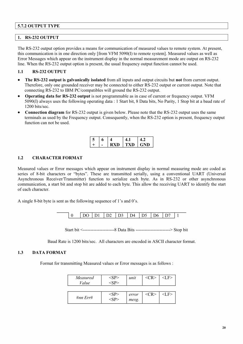
Operating data for RS-232 output is not programmable as in case of current or frequency output. VFM 5090(I) always uses the following operating data : 1 Start bit, 8 Data bits, No Parity, 1 Stop bit at a baud rate of 1200 bits/sec. Connection diagram for RS-232 output is given below. Please note that the RS-232 output uses the same terminals as used by the Frequency output. Consequently, when the RS-232 option is present, frequency output function can not be used.
5 +
6 -
4 RXD
4.1 TXD
4.2 GND
1.2 CHARACTER FORMAT
Measured values or Error messages which appear on instrument display in normal measuring mode are coded as series of 8-bit characters or “bytes”. These are transmitted serially, using a conventional UART (Universal Asynchronous Receiver/Transmitter) function to serialize each byte. As in RS-232 or other asynchronous communication, a start bit and stop bit are added to each byte. This allow the receiving UART to identify the start of each character.
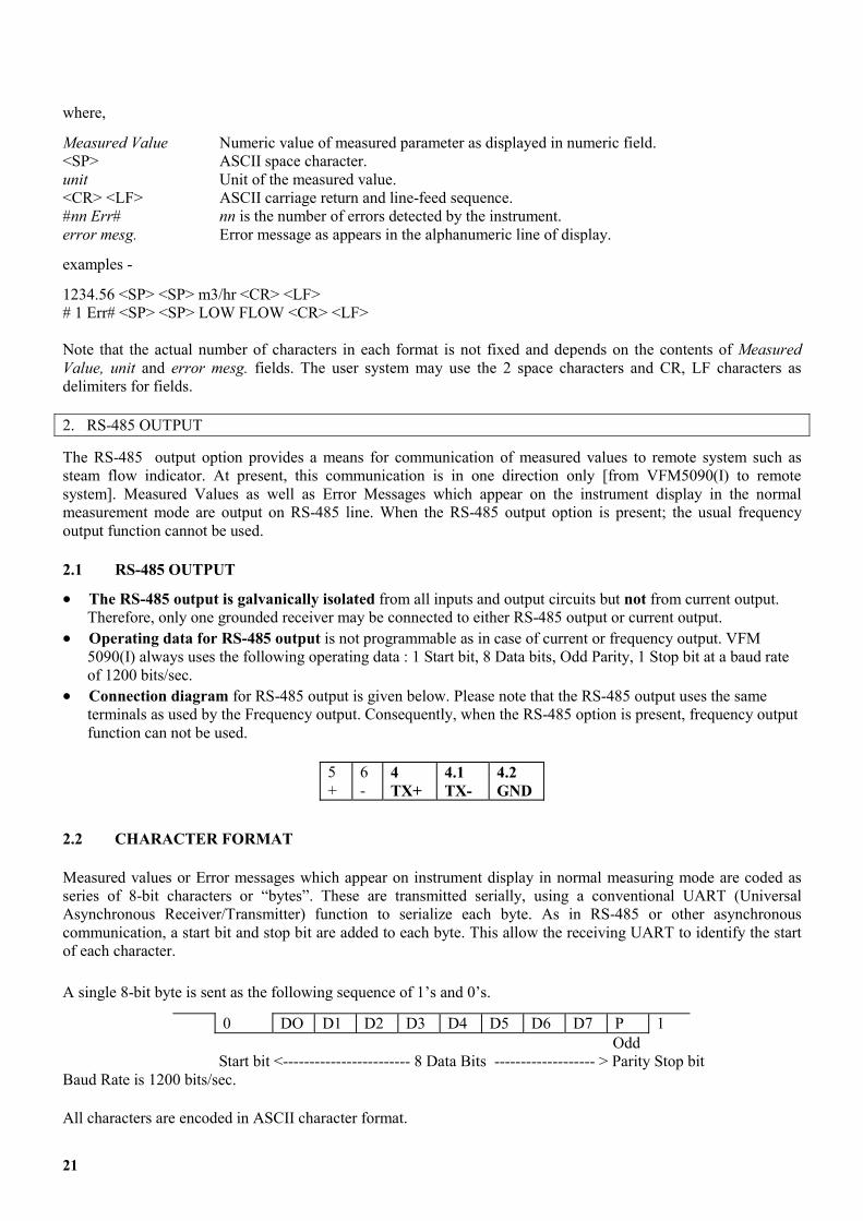
A single 8-bit byte is sent as the following sequence of 1’s and 0’s.
0 DO D1 D2 D3 D4 D5 D6 D7 1
Start bit <---------------------8 Data Bits -----------------------> Stop bit
Baud Rate is 1200 bits/sec. All characters are encoded in ASCII character format.
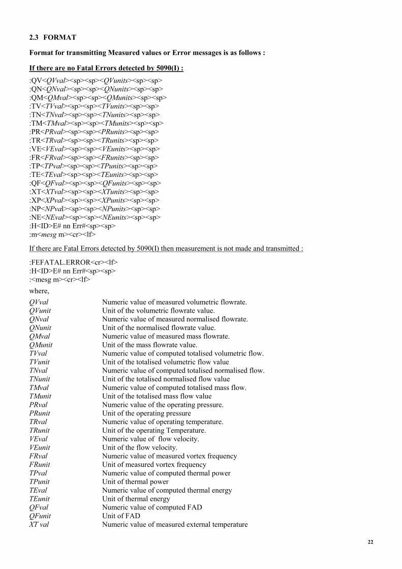
1.3 DATA FORMAT
Format for transmitting Measured values or Error messages is as follows :
Measured
Value <SP> <SP>
unit <CR> <LF>
#nn Err# <SP> <SP>
error mesg.
<CR> <LF>
20
where,
Measured Value Numeric value of measured parameter as displayed in numeric field. <SP> ASCII space character. unit Unit of the measured value. <CR> <LF> ASCII carriage return and line-feed sequence. #nn Err# nn is the number of errors detected by the instrument. error mesg. Error message as appears in the alphanumeric line of display.
examples -
1234.56 <SP> <SP> m3/hr <CR> <LF> # 1 Err# <SP> <SP> LOW FLOW <CR> <LF> Note that the actual number of characters in each format is not fixed and depends on the contents of Measured Value, unit and error mesg. fields. The user system may use the 2 space characters and CR, LF characters as delimiters for fields. 2. RS-485 OUTPUT
The RS-485 output option provides a means for communication of measured values to remote system such as steam flow indicator. At present, this communication is in one direction only [from VFM5090(I) to remote system]. Measured Values as well as Error Messages which appear on the instrument display in the normal measurement mode are output on RS-485 line. When the RS-485 output option is present; the usual frequency output function cannot be used.
2.1 RS-485 OUTPUT
The RS-485 output is galvanically isolated from all inputs and output circuits but not from current output. Therefore, only one grounded receiver may be connected to either RS-485 output or current output.
��
��
��
Operating data for RS-485 output is not programmable as in case of current or frequency output. VFM 5090(I) always uses the following operating data : 1 Start bit, 8 Data bits, Odd Parity, 1 Stop bit at a baud rate of 1200 bits/sec. Connection diagram for RS-485 output is given below. Please note that the RS-485 output uses the same terminals as used by the Frequency output. Consequently, when the RS-485 option is present, frequency output function can not be used.
5 +
6 -
4 TX+
4.1 TX-
4.2 GND
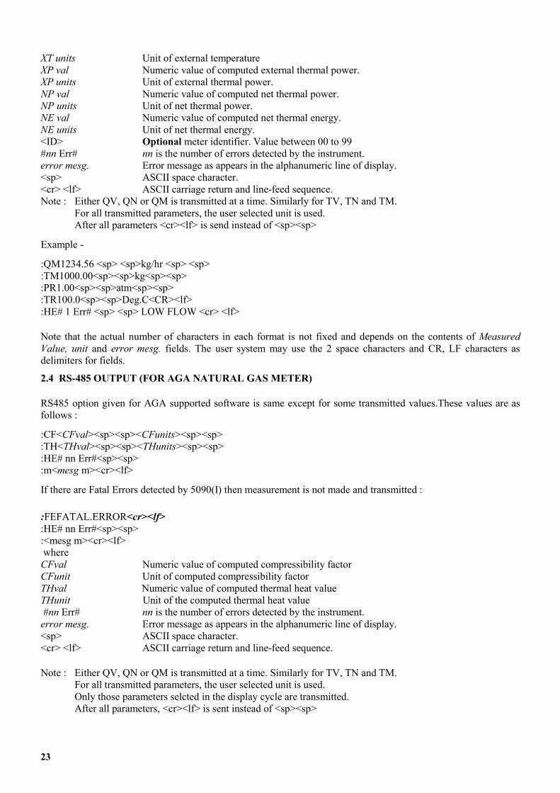
2.2 CHARACTER FORMAT
Measured values or Error messages which appear on instrument display in normal measuring mode are coded as series of 8-bit characters or “bytes”. These are transmitted serially, using a conventional UART (Universal Asynchronous Receiver/Transmitter) function to serialize each byte. As in RS-485 or other asynchronous communication, a start bit and stop bit are added to each byte. This allow the receiving UART to identify the start of each character.
A single 8-bit byte is sent as the following sequence of 1’s and 0’s.
0 DO D1 D2 D3 D4 D5 D6 D7 P 1 Odd Start bit <------------------------ 8 Data Bits ------------------- > Parity Stop bit Baud Rate is 1200 bits/sec.
All characters are encoded in ASCII character format.
21
2.3 FORMAT
Format for transmitting Measured values or Error messages is as follows :
If there are no Fatal Errors detected by 5090(I) :
:QV<QVval><sp><sp><QVunits><sp><sp> :QN<QNval><sp><sp><QNunits><sp><sp> :QM<QMval><sp><sp><QMunits><sp><sp> :TV<TVval><sp><sp><TVunits><sp><sp> :TN<TNval><sp><sp><TNunits><sp><sp> :TM<TMval><sp><sp><TMunits><sp><sp> :PR<PRval><sp><sp><PRunits><sp><sp> :TR<TRval><sp><sp><TRunits><sp><sp> :VE<VEval><sp><sp><VEunits><sp><sp> :FR<FRval><sp><sp><FRunits><sp><sp> :TP<TPval><sp><sp><TPunits><sp><sp> :TE<TEval><sp><sp><TEunits><sp><sp> :QF<QFval><sp><sp><QFunits><sp><sp> :XT<XTval><sp><sp><XTunits><sp><sp> :XP<XPval><sp><sp><XPunits><sp><sp> :NP<NPval><sp><sp><NPunits><sp><sp> :NE<NEval><sp><sp><NEunits><sp><sp> :H<ID>E# nn Err#<sp><sp> :m<mesg m><cr><lf>
If there are Fatal Errors detected by 5090(I) then measurement is not made and transmitted :
:FEFATAL.ERROR<cr><lf> :H<ID>E# nn Err#<sp><sp> :<mesg m><cr><lf> where, QVval Numeric value of measured volumetric flowrate. QVunit Unit of the volumetric flowrate value. QNval Numeric value of measured normalised flowrate. QNunit Unit of the normalised flowrate value. QMval Numeric value of measured mass flowrate. QMunit Unit of the mass flowrate value. TVval Numeric value of computed totalised volumetric flow. TVunit Unit of the totalised volumetric flow value TNval Numeric value of computed totalised normalised flow. TNunit Unit of the totalised normalised flow value TMval Numeric value of computed totalised mass flow. TMunit Unit of the totalised mass flow value PRval Numeric value of the operating pressure. PRunit Unit of the operating pressure TRval Numeric value of operating temperature. TRunit Unit of the operating Temperature. VEval Numeric value of flow velocity. VEunit Unit of the flow velocity. FRval Numeric value of measured vortex frequency FRunit Unit of measured vortex frequency TPval Numeric value of computed thermal power TPunit Unit of thermal power TEval Numeric value of computed thermal energy TEunit Unit of thermal energy QFval Numeric value of computed FAD QFunit Unit of FAD XT val Numeric value of measured external temperature
22
XT units Unit of external temperature XP val Numeric value of computed external thermal power. XP units Unit of external thermal power. NP val Numeric value of computed net thermal power. NP units Unit of net thermal power. NE val Numeric value of computed net thermal energy. NE units Unit of net thermal energy. <ID> Optional meter identifier. Value between 00 to 99 #nn Err# nn is the number of errors detected by the instrument. error mesg. Error message as appears in the alphanumeric line of display. <sp> ASCII space character. <cr> <lf> ASCII carriage return and line-feed sequence. Note : Either QV, QN or QM is transmitted at a time. Similarly for TV, TN and TM. For all transmitted parameters, the user selected unit is used. After all parameters <cr><lf> is send instead of <sp><sp>
Example -
:QM1234.56 <sp> <sp>kg/hr <sp> <sp> :TM1000.00<sp><sp>kg<sp><sp> :PR1.00<sp><sp>atm<sp><sp> :TR100.0<sp><sp>Deg.C<CR><lf> :HE# 1 Err# <sp> <sp> LOW FLOW <cr> <lf>
Note that the actual number of characters in each format is not fixed and depends on the contents of Measured Value, unit and error mesg. fields. The user system may use the 2 space characters and CR, LF characters as delimiters for fields.
2.4 RS-485 OUTPUT (FOR AGA NATURAL GAS METER)
RS485 option given for AGA supported software is same except for some transmitted values.These values are as follows :
:CF<CFval><sp><sp><CFunits><sp><sp> :TH<THval><sp><sp><THunits><sp><sp> :HE# nn Err#<sp><sp> :m<mesg m><cr><lf>
If there are Fatal Errors detected by 5090(I) then measurement is not made and transmitted :
:FEFATAL.ERROR<cr><lf> :HE# nn Err#<sp><sp> :<mesg m><cr><lf> where CFval Numeric value of computed compressibility factor CFunit Unit of computed compressibility factor THval Numeric value of computed thermal heat value THunit Unit of the computed thermal heat value #nn Err# nn is the number of errors detected by the instrument. error mesg. Error message as appears in the alphanumeric line of display. <sp> ASCII space character. <cr> <lf> ASCII carriage return and line-feed sequence.
Note : Either QV, QN or QM is transmitted at a time. Similarly for TV, TN and TM. For all transmitted parameters, the user selected unit is used. Only those parameters selcted in the display cycle are transmitted. After all parameters, <cr><lf> is sent instead of <sp><sp>
23

Example -
:QM1234.56 <sp> <sp>kg/hr <sp> <sp> :TM1000.00<sp><sp>kg<sp><sp> :PR1.00<sp><sp>atm<sp><sp> :TR100.0<sp><sp>Deg.C<CR><lf> :HE# 1 Err# <sp> <sp> LOW FLOW <cr> <lf> Note that the actual number of characters in each format is not fixed and depends on the contents of Measured Value, unit and error mesg. fields. The user system may use the 2 space characters and CR, LF characters as delimiters for fields. Note : In this software QFval computed FAD value is not applicable.
24
+
6.1 Numerical order description 6.1.1 Program function description Program functions are given in numeric order as follows ��
��
��
��
Function number and title DESCRIPTION of the function LIMITS - Applicable limits for numerical input. APPEARS - Conditions when the function
appears. When any function does not appear it is because it is not required
Fct. 1.0 OPERATION
This is the first main menu level. Submenus and their functions grouped under Fct. 1.0 (1.x.x functions) control the operation of the instrument in the following areas.
- Range of flow measurement - Display settings of measured values, units, errors - Current and frequency output programming.
APPEARS - always
Fct. 1.1.0 BASIS.PARAM
The submenu groups the functions that do - Setting of basic flow measurement type
(volumetric/normalized-volumetric/mass flow measurement).
- flow range (minimum & maximum flow) to measure.
- time constant for flow rate.
APPEARS - Always.
Fct. 1.1.1 MEAS. INST. measuring instrument type
Set instrument to measure volumetric or normalized volumetric or mass flow rate as per the options -
� VOLUME � NORM.VOLUME �MASS
Usually, this function is used once initially. If you need to change the basic measurement type later on, you should check/reprogram all flow rate and totalizer related functions such as - MAX.FLOW, MIN.FLOW, FLOW UNITS, TOTAL.UNITS, 0/4mA FLOW, 20mA FLOW, RANGE F, TOT. VALUE
LIMITS - Not applicable APPEARS - Always
Fct. 1.1.2 MAX.FLOW maximum flow rate 6. Description of program functions Enter the maximum flow rate desired. Max. flow should be within the measuring range for the given primary data (3.1.x functions) and application data (3.5.x functions).
The frequency output range value directly corresponds to max. flow. If flow rate exceeds max. flow an error condition (HIGH FLOW) is generated which may affect current output depending on programming of Fct. 1.3.2 RANGE I.
The following units are available to choose from depending on programing of Fct. 1.1.1 MEAS.INST.
for volumetric flow -
� m3/hr � m3/min � m3/sec � Litre/hr � Litre/min � Litre/sec � ft3/hr � ft 3/min � ft3/sec � cft/hr � cft/min � cft/sec � cuft/hr � cuft/min � cuft/sec � US Gal/hr � US Gal/min � US Gal/sec � UK Gal/hr � UK Gal/min � UK Gal/sec
for normalized volumetric flow -
� Norm.m3/hr � Norm.m3/ min � Norm.m3/ sec� Norm.L/hr � Norm.L/min � Norm.L/sec � Sft3/hr � Sft3/min � Sft3/sec � Scft/hr � Scft/min � Scft/sec
for mass flow -
� Kg/hr � kg/min � kg/sec � T/hr � T/min � T/sec � Lb/hr � Lb/min � Lb/sec
LIMITS. - 1 to 10,000,000,000 Practically no limit when entering max. flow. Real check on this parameter is done during plausibility test. For reference see Fct. 4.5 MAX. FLOW.
APPEARS - Always
Fct. 1.1.3 MIN. FLOW minimum flow rate Enter the minimum flow rate in the same units as for max.flow above. Min. flow should be within the measuring range for the given primary data (3.1.X functions) and application data (3.5.X functions). If flow is below min. flow then an error condition (LOW FLOW) will be generated. Note that this value cannot be zero for vortex flowmeters.
LIMITS - > 0 to (0.5* max flow). Higher limit is the 50% of the value entered in Fct. 1.1.2 MAX. FLOW. Real check on this parameter is done during plausibility test. For reference see Fct. 4.6 MIN.FLOW. APPEARS – Always
25
Fct. 1.1.4 TIMECONST. time constant for flow rate
Enter a low-pass filter time constant in seconds to be applied to flow rate. A value of zero indicates that low-pass filter is not to be applied. With this function it is possible to compromise between a steady indication (on display/current output) and response time (to flow changes).
LIMITS - 0 to 20 seconds.
APPEARS - Always.
Fct. 1.2.0 DISPLAY
This submenu groups the display functions which
- Allow selection of units for all measured parameters. - Select what parameters to include in display cycle. - Select display mode (cyclic/non-cyclic) and error messages to appear or not to appear in display cycle.
APPEARS - Alwayss
Fct. 1.2.1 FLOW UNITS for display
Select a unit in which flow rate is to be displayed from the following list of the available units, depending on programming of Fct.1.1.1MEAS. INST.
for volumetric flow -
� m3/hr � m3/min � m3/sec � Litre/hr � Litre/min � Litre/sec � ft3/hr � ft 3/min � ft3/sec � cft/hr � cft/min � cft/sec � cuft/hr � cuft/min � cuft/sec � US Gal/hr � US Gal/min � US Gal/sec � UK Gal/hr � UK Gal/min � UK Gal/sec � % MAX. FLOW
for normalized volumetric flow -
� Norm.m3/hr � Norm.m3/ min � Norm.m3/ sec� Norm.L/hr � Norm.L/min � Norm.L/sec � Sft3/hr � Sft3/min � Sft3/sec � Scft/hr � Scft/min � Scft/sec � % MAX. FLOW
For mass flow -
� Kg/hr � kg/min � kg/sec � T/hr � T/min � T/sec � Lb/hr � Lb/min � Lb/sec � % MAX. FLOW
Note that the list is same as for Fct. 1.1.2 except for an additional unit % MAX. FLOW (to display flow rate as a percentage of max. flow).
LIMITS - Not applicable. APPEARS - Always.
Fct. 1.2.2 TOTAL.UNITS totalizer unit for display
Totalized flow may be displayed in one of the following units.
For volumetric flow -
� m3 � Litre � ft3 � cft � cuft � US Gal � UK Gal � NO DISPLAY
For normalized volumetric flow -
� Norm.m3 � Norm.L � Sft3 � Scft � NO DISPLAY
For mass flow -
� kg � T � Lb � NO DISPLAY
Use NO DISPLAY to exclude totaliser for display cycle.
LIMITS - Not applicable.
APPEARS - Always.
Fct. 1.2.3 TEMP. UNITS for display
The following options exist for temperature unit � Deg. C � Deg. F � KELVIN � NO DISPLAY
Use NO DISPLAY to exclude temperature for display cycle.
LIMITS - Not applicable.
APPEARS - Always.
Fct. 1.2.4 PRES. UNITS pressure unit for display
The following options exist for pressure. Unit with the suffix _g are gauge pressure units and those without the same are absolute pressure units.
� Pa � KPa � atm � Bar � mBar � PSI � Lbf/ft2 � Kg/cm2 � In. Hg � mm Hg � mm Water � pa_g � KPa_g � atm_g � Bar_g � mBar_g � PSI_g � Lbf/ft2_g � Kg/cm2_g � In. Hg_g � mm Hg_g � mm Water_g � NO DISPLAY
Use NO DISPLAY to exclude pressure from display cycle.
LIMITS - Not applicable.
APPEARS - If Fct. 3.5.1 FLUID is not LIQUID.
26
Fct. 1.2.5 VELO. UNITS velocity unit for display
You can choose one of the following � m/Sec � ft/Sec � NO DISPLAY
Select NO DISPLAY if you don’t want this parameter to be displayed.
Fct. 1.2.6 ERROR MSG. display of error messages.
If you want error messages to appear between display of parameters in normal measuring mode, choose YES otherwise select NO.
LIMITS - Not applicable
APPEARS - Always.
Fct. 1.2.7 CYCLE DISP. cyclic/non-cyclic display.
YES means display will cycle automatically. This means a measured parameter is shown in selected units for about 6 seconds and then the next parameter in the display cycle is shown for 6 seconds and so on. NO (non-cyclic display) means the parameter is continuously shown on the display (to see other parameters or to change setting use the � key). You may see error messages in between changeover from one parameter to next if error(s) are present and Fct. 1.2.6 ERROR MSG. is YES.
LIMITS - Not applicable.
APPEARS - Always.
Fct. 1.3.0 CURR.OUTP. I
This submenu groups current output related functions.
APPEARS - Always.
Fct. 1.3.1 FUNCTION I current output function
Choose YES - to make current output active as per functions Fct. 1.3.2 to Fct. 1.3.4 NO makes current output inactive (0 mA).
LIMITS - Not applicable.
APPEARS - Always.
Fct. 1.3.2 RANGE I current output range selection
Here one selects one of the five possible range options. To set current output as 0-20mA or 4-20mA with/without error indication on current output. When a range with suffix of 22=E or 2=E is selected then it means that current output will give 22mA or 2mA
error output if any error(s) are present in the instrument. Range options are listed below. � 0-20 � 4-20 � 0-20/22=E � 4-20/22=E � 4-20/2=E
LIMITS - Not applicable.
APPEARS - If Fct. 1.3.1 FUNCTION I is YES.
Fct. 1.3.3 0/4mA FLOW
Enter the flow value at which you want current output at its minimum 0mA (for 0-20 and 0-20/22=E ranges) or 4mA (for other range options).
LIMITS- 0 to (max_flow-(max_flow-min_flow)* 0.2)
Value is programmable from 0 upto below max_flow by 20% of span.
APPEARS - if Fct. 1.3.1 FUNCTION I is YES
Fct. 1.3.4 20mA FLOW
Enter the flow value at which you want current output at its maximum (20mA). This function and Fct.1.3.3 above define the current output with respect to flow rate. Note that both the points that you define are programmable and don’t have to correspond to min. flow (Fct. 1.1.3) and max. flow (Fct. 1.1.2).
LIMITS - (iqmin + (max_flow-min_flow)*0.2) to 5* max_flow. Where iqmin is the value entered in Fct. 1.3.3 0/4mA FLOW Lower limit ensures a minimum of 20% flow span. Higher limit allows you exceed max_flow by 5 times for current output.
APPEARS : If Fct.1.3.1 FUNCTION I is YES.
Fct. 1.3.5 VARIABLE I Current Output selection function Selects any one of the three options available for current output. Options are listed below : �� FLOW �� POWER �� NET POWER LIMITS : Not applicable APPEARS – If meter type is HEAT METER or NET HEAT METER. For meter type HEAT METER , only flow and power options are available. For meter type NET HEAT METER, all three options are available.
27

Fct. 1.3.6 0/4 mA POWER Enter the power value at which you want current output at its minimum 0 mA or 4 mA. LIMITS : No limits APPEARS : If meter type is HEAT METER or NET HEAT METER and Fct. 1.3.5. VARIABLE I is POWER or NET POWER. Fct. 1.3.7 20 mA POWER Enter the power value at which you want current output at its minimum 20 mA. LIMITS : No limits APPEARS : If meter type is HEAT METER or NET HEAT METER and Fct. 1.3.5. VARIABLE I is POWER or NET POWER
Fct. 1.4.0 FREQ. OUTP. F
This submenu groups frequency output related functions.
APPEARS – Always (Not when output type is RS 485 or RS 232)
Fct. 1.4.1 FUNCTION F frequency output
Choose YES - to make frequency output active as per functions Fct. 1.4.2 to Fct. 1.4.4 NO makes frequency output inactive (0 Hz)
LIMITS - Not applicable.
APPEARS - Always. (Not when output type is RS 485 or RS 232)
Fct. 1.4.2 RANGE F frequency output range value
The frequency output range value is the frequency that corresponds to max. flow (Fct. 1.1.2). The other point is always 0 Hz for 0 flow because frequency output is designed for use with external totalizers. It is also possible to define range f in terms of pulses/unit flow.
Example -
Assume max. flow (Fct. 1.1.2) = 1000 Kg/hr then range f = 10000 pulses/hr (at max. flow) and range f = 10 pulses/Kg are identical. The latter method is better because it is easy to infer that totalizer will have a least count of 0.1 Kg (10 pulses per Kg = 1pulse per 0.1 Kg) and totalizer programming will be independent of max. flow. The various options of units for RANGE F are given below.
For volumetric flow -
� PULSE/hr � PULSE/min � PULSE/sec � PULSE/m3 � PULS/Litre � PULS/ft3 � PULS/cft � PULS/cuft � PULS/US.Gal � PULS/UK. Gal
For normalized volumetric flow -
� PULSE/hr � PULSE/min � PULSE/sec � PUL/NormM3 � PULS/NormL � PULS/Sft3 � PULS/Scft
Or mass flow -
� PULSE/hr � PULSE/min � PULSE/sec � PULS/Kg � PULS/t � PULS/Lb
LIMITS - 0.0028 Hz TO 10,000 Hz. These limits are also applied when programming in pulses per unit flow units. All the necessary conversions for the same are done internally.
APPEARS - If Fct. 1.4.1 FUNCTION F is YES.
Fct. 1.4.3 PULS.WIDTH pulse width
You can limit the duration of maximum active pulse width of the frequency output for frequencies less than or equal to 10 Hz. All options that may appear are listed below. Only the possible options that are available (depending on programming of Fct. 1.4.2 RANGE F) to choose are displayed during actual programming. � 500 mSec � 200 mSec � 100 mSec. � 50 mSec � 30 mSec � 50 %
This function helps to minimize the overheating of electro-mechanical counter coils.
LIMITS - Not applicable.
APPEARS - if Fct. 1.4.1 FUNCTION F is YES.
Fct. 1.4.4 VARIABLE F frequency output selection function Selects any one of the three options available for frequency output. Options are listed below : �� FLOW �� POWER �� NET POWER LIMITS : Not applicable APPEARS – If meter type is HEAT METER or NET HEAT METER. For meter type HEAT METER , only flow and power options are available. For meter type NET HEAT METER, all three options are available.
28
Fct. 1.4.5 F.S. POWER Enter full scale power value at which you want to have max. frequency programmed. LIMITS : No limits APPEARS : If meter type is HEAT METER or NET HEAT METER and Fct. 1.3.5. VARIABLE F is POWER or NET POWER. Fct. 1.4.6 F.S.FREQ. Enter maximum frequency required for maximum power programmed in Fct. 1.4.5 F.S. POWER LIMITS : Maximum 10,000 Hz. APPEARS : If meter type is HEAT METER or NET HEAT METER and Fct. 1.3.5. VARIABLE I is POWER or NET POWER
Fct. 2.0 TEST.
This second main menu level groups test functions for display, current output and frequency output. There are no sub-menus under 2.0. Since these are test functions, when executed they have an immediate effect on the signal converter for the duration the test function is executed. When using all the other menu functions, the changes made are stored temporarily and have no effect on the operation of signal converter unless you quit menu and respond with YES to update changes.
APPEARS - Always
Fct. 2.1 TEST DISP. display test
All segments of the display are tested in the following sequence. Alphanumeric field, numeric field, arrow and key markers. You can press the E key at any time to terminate display test. Executing display test does not affect the normal operation of the signal converter.
LIMITS - Not applicable
APPEARS - Always.
Fct. 2.2 TEST I current output test CAUTION: During this test, current output will change to test values so you should take appropriate actions depending on how you are using current output.
Place current meter in series with current loop then select one of the following values. � 0 mA � 2 mA � 4 mA � 10 mA � 20 mA � 22 mA
Selecting any value will cause that current to flow so that you can check on meter. Select CONT. YES to test other current value or CONT.NO to end. When the menu function finishes, normal current value depending on flow rate and programming of current output function will be restored.
LIMITS - Not applicable.
APPEARS – Always
Fct. 2.3 TEST F frequency output test
CAUTION: During this test frequency output will change to test values so you should take appropriate actions depending on how you are using frequency output
Connect frequency meter to frequency output. Select one of the following test values.
� 1 Hz � 10 Hz � 100 Hz � 1000 Hz � 10000 Hz
Selecting any value will cause that frequency to output so that you can check on meter. Select CONT.YES to test other frequency value or CONT.NO to end. When the menu function finishes, normal frequency value depending on flow rate and programming of frequency output functions will be restored.
LIMITS - Not applicable
APPEARS - Always
Fct. 3.0 INSTALL
This is a main menu level whose submenus and their functions cover all installation related functions which include - Primary data (nominal diameter, k-factor) - User data (language, password, totalizer setting etc.) - Operating limits ( P & T operating limits). - Application data (medium, P & T operating etc.). - Sensor options and pressure sensor data.
APPEARS – Always
29
Fct. 3.1.0 BASIS.PARAM
This submenu function allows the user to enter the vortex primary sensor data viz. nominal diameter and k-factor APPEARS - Always.
Fct. 3.1.1 NOMINAL.DIA nominal diameter
Select from the options which DIN/ANSI size primary is used with the instrument. Options to choose from are - � DN 10 S � DN 10 � DN 15 � DN 20 � DN 25 � DN 40 � DN 50 � DN 80 � DN 100 � DN150 � DN 200 � ANSI 3/8”S � ANSI 3/8” � ANSI ½” � ANSI ¾ ’’ � ANSI 1’’ � ANSI 1.5” � ANSI 2” � ANSI 3” � ANSI 4” � ANSI 6” � ANSI 8” LIMITS - Not applicable
APPEARS - Always
Fct. 3.1.2 K-FACTOR k-factor of the primary
Enter the primary constant k-factor value. This value is stamped on the instrument label in units of pulses/m3
LIMITS - Limits depend on nominal-dia
NOM.DIA LOW LIM HIGH LIM DN 10S/ANSI 3/8” s DN 10 / ANSI 3/8” DN 15 / ANSI ½” DN 20 / ANSI ¾” DN 25 / ANSI 1” DN 40 /ANSI 1.5” DN 50 / ANSI 2” DN 80 / ANSI 3” DN 100 / ANSI 4” DN 150 / ANSI 6” DN 200 / ANSI 8”
1370000 490000 290000 107000 42000 12300 6065 1740 775 240 104
1530000 543000 330000 120000 66000 18700 8800 2730 1200 350 163
APPEARS - Always
Fct. 3.2.0 USER DATA This is submenu level. 3.2.x functions allow selection of dialogue language, setting of password code 1, setting of built-in electronic totalizer Fct. 3.2.1 LANGUAGE dialogue language Instrument supports the following choice at present � ENGLISH � GERMAN � FRENCH
Select the language of your choice. Remember that the selection will have effect when one leaves menu and respond with YES to save changes.
LIMITS - Not applicable
APPEARS - Always
Fct. 3.2.2 ENTRY.CODE.1 entry code 1 password
Select YES if password should be checked to access the menu. Use password to prevent configuration changes by an unauthorized person. Answering NO means password is not required to enter menu.
LIMITS - Not applicable.
APPEARS - Always
Fct. 3.2.3 CODE 1 code 1 password
Enter the actual password which will be required to access menu afterwards from the point after the configuration is saved. Password consists of 9 keystrokes of 3 keys in any order. Display shows 9 empty places initially and gets filled with ‘*’ as you go on entering keystrokes. After 9 keystrokes are over you are again requested to enter the same sequence for verification purpose. If verification is found correct then the function returns to menu level but if something went wrong, function displays WRONG for a couple of seconds (original password, if any, remains unchanged) and then returns to menu
LIMITS - Not applicable
APPEARS - If Fct. 3.2.2 ENTRY CODE 1 is YES.
Fct. 3.2.4 LOCATION installation location
Enter an alphanumeric string upto 10 characters to describe location of installation. This input has no bearing on the performance of the instrument in any way, it merely serves as a means of identification.
LIMITS - Not applicable
APPEARS - Always.
Fct. 3.2.5 TOT.VALUE totalizer value
This function can be used to reset the totalizer (to zero) or to set the totalizer to any starting value. Two options are presented. � RESET � SET.
30
To reset totalizer - Select RESET then select RESET YES as a double confirmation.
To set totalizer - Select SET then enter the value
LIMITS - Setting limits 0 to 1,000,000
APPEARS - Always.
Fct. 3.2.6 TOT. ON/OFF totalizer on/off
Select option TOT. ON to start/restart totalizer and select option TOT. OFF to stop totalizer. Stopping totalizer means flow will not be accumulated till the time totalizer is turned on again.
LIMITS - Not applicable.
APPEARS - Always
Fct. 3.3.0 OPR.LIMITS
This submenu level has functions which allow user to set process temperature and pressure limits. These values should be within the physical limits of the instrument itself. (Physical limits are programmed by KHRONE MARSHALL and user has no access to them. They depend on primary pressure rating and standard or high temperature version). Programming these values are important because it is possible to ascertain whether any limit is being exceeded by the process. To check pressure limits pressure sensor should be present in the primary. Temperature sensor is always present in the primary.
APPEARS - Always.
Fct. 3.3.1 TEMP. LOW temperature low limit
Enter value for operating temperature lower limit. The value can be entered in the following units - � Deg. C � Deg. F � KELVIN
LIMITS - Temp_low_phy to temp_high_phy are the physical limits which are preprogrammed by KHRONE MARSHALL. Typically, the ranges are :- 20 to 180 Deg. C and -20 to 240 Deg. C for standard and high temp. version respectively.
APPEARS - Always.
Fct. 3.3.2 TEMP. HIGH temperature high limit
Enter value for operating temperature higher limit. The value is entered in the same units as in Fct. 3.3.1 above.
LIMITS - temp_low_opr to temp_high_phy. temp_low_opr is temperature value entered in Fct. 3.3.1 TEMP.LOW.
APPEARS - Always.
Fct. 3.3.3 PRES. LOW pressure low limit
Enter value for operating pressure lower limit. The value can be entered in the following units. Unit with the _g suffix are gauge pressure units and those without the same absolute pressure units. � Pa � KPa � atm � Bar � mBar � PSI � Lbf/ft2 � Kg/cm2 � In. Hg � mm Hg � mm Water � Pa_g � KPa_g � atm_g � Bar_g � mBar_g � PSI_g � Lbf/ft2_g � Kg/cm2-g � In. Hg_g � mm Hg_g � mm Water_g LIMITS - Pres_low_phy to pres_high_phy above are the physical limits which are preprogrammed by KHRONE MARSHALL, depending on the pressure rating of primary.
APPEARS - Always.
Fct. 3.3.4 PRES. HIGH pressure high limit
Enter value for operating pressure higher limit. The value is entered in the same units as in Fct. 3.3.3 above.
LIMITS - Pres_low_opr to pres_high_phy pres_low_opr is pressure value entered in Fct. 3.3.3 PRES.LOW.
APPEARS - Always.
Fct. 3.5.0 APPLICAT.
This submenu groups functions which allow to view/enter the application data. These functions gives the following information to the instrument. - process medium - operating temperature and pressure conditions. - density of medium at operating conditions. Required only if software within instrument do not support the medium (Fct. 3.5.2 is selected as -NONE-). - normal or reference P & T values required for normalized flow measurements only (depending on Fct. 1.1.1). Usual values are temp.norm=0 or 200 C and pres.norm=1 atm. - density at normal conditions. Required only for normalized volumetric flow and if software within instrument does not support the medium (Fct. 3.5.2 is selected as -NONE-). APPEARS - Always.
31
Fct. 3.5.1 FLUID fluid type
Select whether process medium is Steam, Gas (including air), Mixture of gases, Moist gas or Liquid. � STEAM � GAS � GAX MIX � WET GAS � LIQUID
LIMITS - Not applicable
APPEARS - Always.
Fct. 3.5.2 MEDIUM process medium
Select the medium from the options given below. If the medium used is not included in the option list select -NONE-. For all the mediums except -NONE- instrument software calculates density of the medium from P & T conditions which is required for meter sizing, mass flow and normalized flow computations. However, for unsupported medium user has to supply density at operating P & T and density at normal P & T (latter for normalized flow only)
Options for fluid STEAM -
� SAT STEAM � SUP STEAM
(Saturated and superheated steam)
Options for fluid Gas
� AIR � AMMONIA � ARGON � I-BUTANE � N-BUTANE � CO � CO2 � ETHANE � ETHYLENE � HEXANE � HYDROGEN � H2S � METHANE � NEON � NITROGEN � OXYGEN � I-PENTANE � N-PENTANE � PROPANE � XENON � -NONE-
(CO is carbon monoxide, CO2 is carbon dioxide, -NONE- is none of the above)
Option for fluid WET GAS
� AIR � AMMONIA � ARGON � I-BUTANE � N-BUTANE � CO � CO2 � ETHANE � ETHYLENE � HEXANE � HYDROGEN � H2S � METHANE � NEON � NITROGEN � OXYGEN � I-PENTANE � N-PENTANE � PROPANE � XENON
Option for fluid LIQUID
� WATER � -NONE-
LIMITS - Not applicable
APPEARS - Fluid is other than GAS MIX.
Fct. 3.5.3 SAT. P/T use saturation P or T
For saturated steam only one of the operating temperature or pressure is needed for density calculation. Select whether you are going to specify saturation temp. or pressure from the following options - � SAT TEMP � SAT.PRES. Actual value of temp. or pressure is to be entered under Fct. 3.5.6 TEMP.OPR or Fct. 3.5.7 PRES.OPR.
LIMITS - Not Applicable
APPEARS - if fluid is STEAM and medium is SAT STEAM
Fct. 3.5.4 % GAS MIX percentage of gases
Select the components of gas mixture. Enter the mole fraction percentage of gases present in the mixture of gases. The list of gases available is given below. For the components not present in the mixture, keep the percentages as zero. The sum of percentages of gas components should be equal to 100 � 0.1.
List of gases for fluid GAS MIX -
� AMMONIA � ARGON � I-BUTANE � N-BUTANE � CO � CO2 � ETHANE � ETHYlENE � HEXANE � HYDROGEN � H2S � METHANE � NEON � NITROGEN � OXYGEN � I-PENTANE � N-PENTANE � PROPANE � XENON
LIMITS - 0 to 100 % for each gas.
APPEARS - if fluid is GAS MIX
Fct. 3.5.5. % REL HUM Relative humidity
Enter relative humidity of moist gas in the range of zero to hundred.
LIMITS - 0 to 100 %
APPEARS - if fluid is WET GAS
Fct. 3.5.6 TEMP. OPR operating temperature
Enter the mean (average) operating temperature of the medium. This parameter is very important since it is involved in the following - Flow range check - During plausibility check, flow range of measurement is computed to see that Fct. 1.1.2 MAX FLOW and Fct. 1.1.3 MIN. FLOW are plausible. This calculation is function of nom.
32

diameter, fluid, medium and density. Where density depends on temp. operating for all mediums except -NONE- Flow computations - When temp. sensor is not present, value given here is used in flow computations for all mediums except -NONE- Temperature value can be entered in one of the units same as in Fct. 3.3.1.
LIMITS - Temp_low_opr to temp_high_opr
Limits for operating temp. are the operating temp. range as given in -
Fct 3.3.1 TEMP. LOW and Fct. 3.3.2 TEMP. HIGH.
APPEARS - Does not appear if medium is saturated steam and Fct. 3.5.3 SAT. P/T is set to SAT. PRES.
Fct. 3.5.7 PRES. OPR operating pressure
Enter the mean (average) operating pressure of the medium. This parameter is very important since it is involved in the following -
Flow range check - During plausibility check, flow range of measurement is computed to see that Fct. 1.1.2 MAX. FLOW and Fct. 1.1.3 MIN. FLOW are plausible. This calculation is function of nom. diameter, k-factor, fluid, medium and density. Where density depends on operating pressure for all mediums except -NONE-.
Flow computations - When pressure sensor is not present, value given here is used in flow computations for mass or normalized flow computations for mass or normalized flow and for all mediums except -NONE-. Pressure value can be entered in one of the units same as in Fct. 3.3.3.
LIMITS - Pres_low_opr to pres_high_opr
Limits for operating pressure are the operating pressure range given in Fct. 3.3.3 PRES. LOW and Fct. 3.3.4 PRES. HIGH.
APPEARS - Does not appear if -
1. Medium is saturated steam & Fct. 3.5.3 SAT. P/T is set to SAT. TEMP or
2. Fluid is Liquid.
Fct. 3.5.8 DENS. OPR. density at operating P&T
Enter the density of medium at operating pressure and temp. conditions. The value can be entered in one of the following units - � Kg/m3 � Kg/Litre � Lb/ft3
� Lb/cft LIMITS - 0.6 to 100Kg/m 3
APPEARS - If fluid is GAS and medium is NONE -
Fct. 3.5.9 TEMP. NORM normal temperature
Enter value for normal/base/reference temperature.
This value is usually 00 or 200 C. Unit options for this value are the same as in FCT. 3.3.1.
LIMITS - 0 to 50 Deg. C.
APPEARS - if Fct. 1.1.1 MEAS. INST is NORM. VOLUME. Fct. 3.5.10 PRES. NORM normal pressure
Enter value for normal/base/reference pressure. This value is usually 1 atm. Unit options for this value are the same as in Fct. 3.3.3.
LIMITS - 0.1 to 10 bar
APPEARS - if Fct. 1.1.1 MEAS. INST is NORM.VOLUME and fluid is not LIQUID.
Fct. 3.5.11 DENS.NORM. density at normal P&T
Enter the density of medium at normal pressure and temp. conditions. The value can be entered in one of the following units - � Kg/m3 � Kg/Litre � Lb/ft3 � Lb/cft
LIMITS - 0.6 to 100 Kg/m3
APPEARS - if Fct. 1.1.1 MEAS.INST is NORM.VOLUME and fluid is GAS and medium is -NONE-
Fct. 3.6.0 OPTIONS Functions under this submenu allow one to inform instrument whether pressure sensor and temperature sensor are installed.
APPEARS - Always.
Fct. 3.6.1 T-SENSOR temperature sensor
Select YES if temperature sensor option is present else select NO.
LIMITS - Not applicable.
APPEARS - Always
33
Fct. 3.6.2 P-SENSOR pressure sensor
Select YES if pressure sensor option is present else select NO.
LIMITS - Not applicable.
APPEARS - If fluid is not LIQUID. Fct. 3.6.3 RS485 ID RS485 identifier
Use this menu to select whether identifier of the meter should be used in RS485 transmission. If YES is selected, then identifier number for the meter can be entered using Fct. 3.6.4 METER ID menu.
LIMITS - Not applicable
APPEARS - If output type of the meter is selected as RS 485.
Fct. 3.6.4 METER ID Meter identifier
Use this menu to set the RS485 identifier number for the meter. This number is used in RS485 transmission and is transmitted with every data frame if Fct. 3.6.3 RS485 ID is selected as YES.
LIMITS - 0 to 99
APPEARS - If output type of the meter is selected as RS 485 and Fct. 3.6.3 RS485 ID is selected as YES.
Fct. 3.7.0 P-DATA
This submenu groups functions which input the pressure sensor calibration data. Pressure sensor calibration data (mV output vs. pressure) is obtained at two temperatures. So, it is possible to compensate pressure sensor for temperature variations.
APPEARS - If FLUID is not LIQUID and Fct. 3.6.2 P-SENSOR is YES.
Fct. 3.7.1 T1 calibration temperature 1
Enter the calibration temperature 1. Units possible to use are same as in Fct. 3.3.1.
LIMITS - 20 to 100 Deg. C.
APPEARS - if Fct. 3.6.2 P-SENSOR is YES and FLUID is not LIQUID.
Fct. 3.7.2 P11 V11 calibration point 1 at T1
Enter pressure value (in one of the units same as in Fct. 3.3.3) and the corresponding milli-volt value. LIMITS - 0 to 40 Bar for P11. 0 to 25 mV for V11.
APPEARS - if Fct. 3.6.2 P-SENSOR is YES and fluid is not LIQUID.
Fct. 3.7.3 P12 V12 calibration point 2 at T1
Enter pressure value (same unit assumed as in Fct. 3.7.2) and the corresponding milli-volt value. LIMITS - 5 to 100 Bar for P12. 40 to 125 mV for V12.
APPEARS - If Fct. 3.6.2 P-SENSOR is YES and fluid is not LIQUID.
Fct. 3.7.4 T2 calibration temperature 2
Enter the calibration temperature 2. Unit is assumed same as selected in Fct.3.7.1. LIMITS - 101 to 200 Deg. C. APPEARS - If Fct. 3.6.2 P-SENSOR is YES and fluid is not LIQUID.
Fct. 3.7.5 P21 V21 calibration point 1 at T2
Enter pressure value (unit assumed to be same as selected in Fct. 3.7.2) and the corresponding milli-volt value. LIMITS - 0 to 40 Bar for P21. 0 to 25 mV for V21.
APPEARS - If Fct. 3.6.2 P-SENSOR is YES and fluid is not LIQUID.
Fct. 3.7.6 P22 V22 Calibration point 2 at T2
Enter pressure value (same unit assumed as in Fct.3.7.2) and the corresponding milli-volt value. LIMITS - 5 to 100 Bar for P22 40 to 125 mV for V22
APPEARS - if Fct. 3.6.2 P-SENSOR is YES and fluid is not LIQUID.
Fct. 3.8.0 HEAT PARA.
This submenu groups functions which allow to view/enter the heat meter power/energy calculation related data. These functions give the following information to the instrument - Units for power - Units for energy - Energy totalizer Reset/Set - Energy totalizer ON/OFF - Dryness factor for Saturated steam applications.
APPEARS - If Fct. 1.1.1 MEAS. INST is MASS and Fct. 3.5.1 FLUID is STEAM or LIQUID.
Fct. 3.8.1 POWER. UNITS thermal power units 34

Thermal power may be displayed in one of the following units. � KJ/hr � MJ/hr � GJ/hr � BTU/hr � KCal/hr � KW � MW � NO DISPLAY LIMITS - Not Applicable
APPEARS - Always.
Fct. 3.8.2 ENER UNITS thermal energy units
Thermal energy may be displayed in one of the following units. These units are used for energy totalizer. � KJ � MJ � GJ � BTU � KCal � KWH � MWH � NO DISPLAY LIMITS - Not Applicable APPEARS - Always
Fct. 3.8.3 E. TOT.VAL energy totalizer value
This function can be used to reset the energy totalizer (to zero) or to set the totalizer to any starting value. Two options are presented – � RESET � SET
LIMITS - 0 to 1,000,000
APPEARS - Always
Fct. 3.8.4 ETOT.ON/OFF energy totalizer on/off
Select option TOT.ON to start/restart energy totalizer and select option TOT.OFF to stop energy totalizer. Stopping energy totalizer means energy value will not be accumulated till the time the energy totalizer is turned on again.
LIMITS - Not Applicable.
APPEARS - Always.
Fct. 3.8.5 DRY.FACT dryness factor
Enter dryness factor for Saturated Steam.
LIMITS - 0.85 to 1.0
APPEARS - If Fct. 3.5.1 FLUID is STEAM and Fct. 3.5.2 MEDIUM is SAT.STEAM
Fct. 3.8.6 NT.PWR UNITS Net thermal power units. Thermal power can be displayed in any one of the following units. � KJ/hr � BTU/hr � GJ/hr � MW � MJ/h � KCAL/hr � KW � NO DISPLAY LIMITS : Not applicable APPEARS : If meter is NET HEAT METER Fct. 3.8.7 NT.PWR UNITS Net thermal energy units. Thermal energy can be displayed in any one of the following units. � KJ � MJ � GJ � BTU � KcaL � KWH � MWH � NO DISPLAY LIMITS : Not applicable APPEARS : If meter type is NET HEAT METER. Fct. 3.8.8 NT.EN.TOT.VAL Net energy totalizer value. This function can be used to reset the totalizer to zero or to set it to any starting value. Two options are presented. �� RESET �� SET To reset the totalizer – select RESET then select RESET YES as a double confirmation. To set totalizer – select SET then enter the value. LIMITS - Setting limits 0 to 10,00,000 APPEARS : If meter is NET HEAT METER Fct. 3.8.9 NE.TOT.ON/OFF Net energy totalizer on/off Select option TOT.ON/OF to start/restart the totalizer and select TOT,OFF to stop thre totalizer means net power will not be accumulated till the time totalizer is turned on again. LIMITS - Not Applicable. APPEARS : If meter is NET HEAT METER Note : If the NET HEAT METER option is selected, only two of the three totalizers i.e. flow totalizer energy totalizer ,net energy totalizer can be selected at a time and not all the three.
35
Fct.3.8.10 EXT.TEMP.UNIT.External temperature display unit. This selects unit to display temperature of the external temperature sensor. The options available are � Deg. C � Deg. F � KELVIN � NO DISPLAY Fct. 3.8.11 EXT. TEMP. F. S. External tempertaure full scale value. This function is used to enter the full scale value of the external tempertaure sensor. LIMITS :Upto 300 Deg. C APPEARS : If meter type is NET HEAT METER. Fct. 3.8.12 EXT. POWER UNITS This function is used to select the units to display thermal power at external temperature sensor location. The options avaliable are � KJ/hr � MJ/hr � GJ/hr � BTU/hr � KW � MW � NO DISPLAY Fct. 3.8.13 EX. DRY.FACT. External dryness factor. Enter dryness factor for saturated steam. LIMITS : from 0 to 1 APPEARS : If meter type is NET HEAT METER and Fct.3.5.1 FLUID is STEAM. Fct. 3.8.14 SEL. PROCESS Select process. This function is used to select the process. Options available are � HEAT T1>T2 � CHILL T2 > T1 � DON’T CARE LIMITS :Not applicable. APPEARS :If meter type is NET HEAT METER. Fct. 3.8.15 NULL TEMP. This function is used to null the difference between temperature sensors T1 & T2 in the plant when plant is not running. This eliminates the error in the calculation due to offset in same temperature reading if measured by two different temperature sensors. LIMITS - max 3 deg. C APPEARS – If meter type is NET HEAT METER.
Fct 3.9.0 FAD PARA
This submenu level has functions which allow user to program all operating data for FAD application.
APPEARS - If meter type is FAD meter.
Fct. 3.9.1 FAD UNITS units for FAD
Select unit for display of parameter FAD Volume flow. (FAD flow is vol. flow as calculated by meter at the suction side of compressor.). � FAD.m3/hr � FAD.m3/min � FAD.m3/sec � FAD.L./hr. � FAD.L./min � FAD.L./sec � FAD.ft3/hr � FAD.ft3/min � FAD.ft3/sec � FAD.cft/hr � FAD.cft/min � FAD.cft/sec � NO DISPLAY LIMITS - Not Applicable
APPEARS - Always
NOTE: If the unit selected is NO DISPLAY then all other Fct.3.9.x functions are not shown and FAD calculations are not performed by VFM 5090(I)
Fct. 3.9.2 TEMP.SUCT suction temperature
Enter the suction temperature in any of the following units - � Deg. C � Deg. F � KELVIN LIMITS - 200C to 700C
APPEARS - Please refer to the NOTE.
Fct. 3.9.3 PRES. ATM. atmospheric pressure
Enter atmospheric pressure. Possible units for this parameter are - � Pa � KPa � atm � Bar � mBar � PSI. � Lbf/ft2 � Kg/cm2 � In.Hg. � mm Hg � mm Water � Pa_g � KPa_g � atm_g � Bar_g � mBar_g � PSI_g � Lbf/ft2_g � Kg/cm2_g � In. Hg_g � mm Hg_g � mm Water_g LIMITS - 0.5 to 2.0 atm
APPEARS - Please refer to the NOTE.
36
Fct. 3.9.4 PRES. FDROP Filter Pressure drop
Enter value of pressure drop across the filter at the inlet of the compressor. (If there is no such filter installed then keep this value as zero).
Units for this parameter entry are
� Pa � KPa � atm. � Bar � mBar � PSI. � Lbf / ft2 � Kg/cm2 � In. Hg. � mm Hg � mm Water � Pa_g � KPa_g � atm_g � Bar_g � mBar_g � PSI_g � Lbf / ft2_g � Kg / cm2_g � In. Hg_g � mm Hg_g � mm Water_g LIMITS - 0 to 2.0 atm.
APPEARS - Please refer to the NOTE.
Fct. 3.9.5 RH SUCT. Relative humidity at suction
Enter the relative humidity at the suction side (i.e. ambient air). Units are % RH.
LIMITS - 0 to 100
APPEARS - Please refer to the NOTE.
Fct. 3.9.6 RPM ACTUAL actual rpm
Enter the measured speed of the compressor motor in RPM.
LIMITS - 0 to 10000
APPEARS - Please refer to the NOTE
Fct. 3.9.7 RPM RATED rated rpm
Enter the rated speed of the compressor motor in RPM.
LIMITS - 0 to 10000
APPEARS - Please refer to the NOTE.
Fct. 3.9.8 RH OP relative humidity operating
Enter the relative humidity at the meter side (i.e Compressor outlet side). Typically this value is 100%. Units are % RH.
LIMITS - 0 to 100 APPEARS - Please refer to the NOTE.
Fct. 4.0 PARAM.ERROR
Parameter Error menu level appears if parameter check fails in the plausibility tests. There are no submenus under this level. When this menu is displayed use the � key to see the functions which need be corrected. When you correct the parameter, that function instantly disappears from the 4.x. list and when all such function parameters are corrected, menu automatically returns to 4.0 level.
APPEARS - if plausibility test detects errors when attempting to save the configuration in non-volatile memory.
Fct. 4.1 K-FACTOR k-factor of the primary
Enter the primary constant k-factor value. This value is stamped on the instrument label and in units of pulses/m3.
LIMITS - Limits are same as those given in Fct. 3.1.2
APPEARS - if k-factor is outside its limits (due to change in the nominal diameter.)
Fct. 4.2 TEMP. OPR operating temperature
Enter the mean (average) operating temperature of the medium. This parameter is very important since it is involved in the following -
Flow range check - During plausibility check, flow range of measurement is computed to see that Fct. 1.1.2 MAX.FLOW and Fct. 1.1.3 MIN. FLOW are plausible. This calculation is function of nom. diameter, k-factor, fluid, medium and density. Where density depends on temp. operating for all mediums except -NONE-.
Flow computations - When temp. sensor is not present, value given here is used in flow computations for mass or normalized flow and for all mediums except -NONE- Temperature value can be entered in one of the units same as in Fct. 3.3.2.
LIMITS - Limits are same as those given in Fct. 3.5.6
APPEARS - if operating temp. is outside its limit. This may happen if operating temp. range is changed without changing operating temp. such that the operating temp. is outside its limits.
37
Fct. 4.3 PRES.OPR operating pressure
Enter the mean (average) operating pressure of the medium. This parameter is very important since it is involved in following -
Flow range check - During plausibility check, flow range of measurement is computed to see that Fct. 1.1.2 MAX. FLOW and Fct. 1.1.3 MIN. FLOW are plausible. This calculation is function of nom. diameter, k-factor, fluid, medium and density. Where density depends on operating pressure for all mediums except -NONE-
Flow computations - When pressure sensor is not present, value given here is used in flow computations for mass or normalized flow for all mediums except -NONE- Pressure value can be entered in one of the units same as in Fct. 3.3.3.
LIMITS - Limits are same as those given in the Fct.3.5.7.
APPEARS - if operating pressure is outside its limits. This may happen if operating pressure range is changed without changing the operating pressure such that the operating pressure is outside its valid limits.
Fct. 4.4 % GAS MIX Percentage of gases
Select the components of gas mixture. Enter the mole fraction percentage of gases present in the mixture of gases. The list of gases available is given below. For the components not present in the mixture, keep the percentage as zero. The sum of percentages of gas components should be equal to 100 � 0.1
List of gases for fluid GAS MIX -
� AMMONIA � ARGON � I-BUTANE � N-BUTANE � CO � CO2 � ETHANE � ETHYLENE � HEXANE � HYDROGEN � H2S � METHANE � NEON � NITROGEN � OXYGEN � I-PENTANE � N-PENTANE � PROPANE � XENON LIMITS - 0 to 100 % for each gas
APPEARS - if fluid is GAS MIX.
Fct. 4.5 MAX. FLOW maximum flow rate
Enter the maximum flow rate desired. Max. flow should be within measuring range for the given primary data (3.1.x functions) and application data (3.5.x functions). The frequency output range value
directly corresponds to max. flow. If flow rate exceeds max. flow an error condition ( HIGH FLOW) is generated which may affect current output depending on programming of Fct. 1.3.2 RANGE I. The following units are available to choose from depending on programming of Fct. 1.1.1 MEAS. INST.
For volumetric flow -
� m3/hr � m3/min � m3/sec � Litre/hr � Lirtre/min � Litre/sec � ft3/hr � ft3/min � ft3/sec � cft/hr � cft/min � cft/sec � cuft/hr � cuft/min � cuft/sec � US Gal/hr � US Gal/min � US Gal/sec � UK Gal/hr � UK Gal/min � UK Gal/sec
For normalized volumetric flow -
� Norm.m3/hr � Norm.m3/min � Norm.m3/sec � Norm.L./hr � Norm.L./min � Norm.L./sec � Sft3/hr � Sft3/min � Sft3/sec. � Scft/hr � Scft/min � Scft/sec
or mass flow –
� Kg/hr � Kg/min � Kg/sec � T/hr � T/min � T/sec � Lb/hr � Lb/min � Lb/sec
LIMITS - Limit is calculated from the sizing calculation from the application data and primary data. Sizing involves :
�� Calculation of density at operating conditions. (User supplied value is used for unsupported medium -NONE).
�� calculation of minimum velocity, Vmin, from the graph of velocity vs. density. See diag. III in section Technical data.
�� Maximum flow velocity, Vmax = 135.7306 /��op for sizes DN25 to 200( 1” to 8”) = 83.87146 / ��op for sizes DN10S to 20( 3/8”S to 3/4”) In both cases Vmax is clamped at 75m/s. For densities at and above 50kg/m3, Vmin is fixed at 0.94192 m/s for all sizes. �� Volumetric flow limits are qv_min = Vmin*area
& qv_max = Vmax*area. �� Normalized volumetric flow rate limits are
qvn_min = qv_min *opr_density/norm_density and qvn_max = qv_max*opr_density/norm_density.
�� Mass flow rate limits are qm_min = qv_min*opr density and qm_max = qv_max*opr_density.
38
APPEARS - if max. flow Fct. 1.1.2 MAX.FLOW is outside the measuring range of the instrument. Metering range is computed by sizing the application as explained in the limits above.
Fct. 4.6 MIN. FLOW minimum flow rate
Enter the minimum flow rate in the same units as for MAX. FLOW above. MIN. FLOW should be within the measuring range for the given primary data (3.1.x functions) and application data (3.5.x functions). If flow rate measured is below min. flow then an error condition (LOW FLOW) will be generated. Note that this value cannot be zero for vortex flowmeters.
LIMITS - Limit is calculated from the sizing calculations from the application data and primary data. For details of sizing see above paragraph.
APPEARS - if min. flow entered in Fct. 1.1.3 MIN. FLOW is outside the measuring range of instrument. Metering range is computed by sizing the application.
Fct. 4.7 0/4mA FLOW Enter the flow value at which you want current output at its minimum 0mA (for 0-20 and 0-20/22 =E ranges) or 4mA (for other range options).
LIMITS - Limits are the same as those mentioned in Fct. 1.3.4. 0/4mA FLOW.
APPEARS - If value entered in Fct. 1.3.3 0/4mA FLOW lies outside its limits (due to change in flow range).
Fct. 4.8 20mA FLOW enter the flow value at which you want current output at its maximum (20mA). This function and Fct. 1.3.3. above define the current output with respect to flow rate. Note that both the points that you define are programmable and independent of min. Flow (Fct. 1.1.3) and max. flow (Fct. 1.1.2.)
LIMITS - Same as in Fct. 1.3.4 20 mA FLOW.
APPEARS - if value entered in Fct. 1.3.4 20mA FLOW lies outside its limits (due to change in flow range).
Fct. 4.9 RANGE F frequency output range value
The frequency output range value is the frequency that corresponds to max. flow ( Fct. 1.1.2 ). The other point is always 0 Hz for 0 flow because frequency output is designed for use with external totalizers. It is also possible to define range f in terms of pulses/unit flow . Example -
Assume max. flow (Fct. 1.1.2) = 1000 Kg/hr then range f = 10000 pulses/hr (at max. flow) and range f = 10 pulses/Kg are identical. The latter method is better because it is easy to infer that totalizer will have a least count of 0.1 Kg ( 10 pulses per Kg = 1 pulse per 0.1 Kg) and totalizer programming will be independent of max. flow. The various options of units for range f are given below.
for volumetric flow -
� PULSE/hr � PULSE/min � PULSE/sec � PULSE/m3 � PULS/Litre � PULS/ft3 � PULS/cft � PULS/cuft � PULS/US.Gal � PULS/UK.Gal
for normalized volumetric flow - � PULSE/hr � PULSE/min � PULSE/sec � PUL/Norm. m3 � PULS/Norm.l � PULS/sft3 � PULS/Scft or mass flow - � PULSE/hr � PULSE/min � PULSE/sec � PULS/Kg � PULS/t � PULS/Lb
LIMITS - 0.0028Hz to 10,000 Hz (Same limits as in Fct. 1.4.2 RANGE F.)
APPEARS - if value entered in Fct. 1.4.2 RANGE F lies outside its limits (due to change in flow range without subsequently changing Fct. 1.4.2 and invalidating its limit).
Fct. 4.10 PULS. WIDTH pulse width
You can limit the duration of maximum active pulse width of the frequency output for frequencies less than or equal to 10 Hz. All options that may appear are listed below. Only the possible options that are available (depending on programming of Fct. 1.4.2 RANGE F) to choose are displayed during actual programming � 500 mSec. � 200 mSec � 100 mSec � 50 mSec. � 30 mSec � 50%
This helps minimize the overheating of totalizer coils.
LIMITS - Not applicable
APPEARS - if value entered in Fct. 1.4.2 RANGE F is changed such that the existing pulse-width option is now not valid.
F
M
�
39
6.1.2. Program function description for AGA supported software
ct. 3.8.5 H_VAL.UNITS Heating value units
ay be displayed in one of the following units.
KJ / m3 � MJ / m3 � GJ / m3
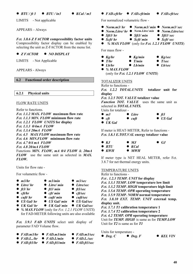
� BTU / ft 3 � BTU / in3 � KCal / m3
LIMITS - Not applicable
APPEARS – Always
Fct. 3.8.6 Z FACTOR compressibility factor units Compressibility factor display can be enabled by selecting the unit as Z-FACTOR from the menu list.
� Z FACTOR � NO DISPLAY
LIMITS - Not Applicable
APPEARS - Always
6.2 Functional order description
6.2.1 Physical units
FLOW RATE UNITS
Refer to functions. Fct. 1.1.2 MAX. FLOW maximum flow rate Fct. 1.1.3 MIN. FLOW minimum flow rate Fct. 1.2.1 FLOW UNITS for display Fct. 1.3.3 0/4mA FLOW Fct. 1.3.4 20mA FLOW Fct. 4.5 MAX FLOW maximum flow rate Fct. 4.6 MIN.FLOW minimum flow rate Fct. 4.7 0/4 mA FLOW Fct. 4.8 20/mA FLOW Functions MIN. FLOW, mA 0/4 FLOW & 20mA FLOW use the same unit as selected in MAX. FLOW. Units for flow rate -
For volumetric flow -
� m3/hr � m3/min � m3/sec � Litre/ hr � Litre/ min � Litre/sec � ft3/ hr � ft3/ min � ft3/sec � cft/hr � cft/ min � cft/sec � cuft/ hr � cuft/ min � cuft/sec � US Gal/ hr � US Gal/ min � US Gal/sec � UK Gal/ hr � UK Gal/ min � UK Gal/sec � % MAX FLOW (only for Fct. 1.2.1 FLOW UNITS)
for FAD-METER following units are also available Fct. 3.9.1 FAD UNITS select unit display of parameter FAD Volume flow. � FAD.m3/hr � FAD.m3/min � FAD.m3/sec � FAD.L../hr � FAD.L/min � FAD.L./sec � FAD.ft3/hr � FAD.ft3/min � FAD.ft3/sec
� FAD.cft/hr � FAD.cft/min � FAD.cft/sec
For normalized volumetric flow -
� Norm.m3/ hr � Norm.m3/ min � Norm.m3/ sec � Norm.Litre/ hr � Norm.Litre/ min � Norm.Litre/sec� Sft3/ hr � Sft3/ min � Sft3/ sec � Scft/ hr � Scft/ min � Scft/ sec
� % MAX FLOW (only for Fct. 1.2.1 FLOW UNITS)
For mass flow -
� Kg/hr � Kg/min � Kg/sec � T/hr � T/min � T/sec � Lb/hr � Lb/min � Lb/sec � % MAX FLOW
(only for Fct. 1.2.1 FLOW UNITS) TOTALIZER UNITS Refer to functions - Fct. 1.2.2 TOTAL.UNITS totalizer unit for display Fct. 3.2.5 TOT. VALUE totalizer value Function TOT. VALUE uses the same unit as selected in TOTAL.UNITS. Units for totalizer - � m3 � Litre � ft3 � cft � cuft � US Gal � UK Gal If meter is HEAT-METER, Refer to functions - Fct. 3.8.3 E.TOT.VAL energy totalizer value � KJ � MJ � GJ � BTU � KCal � KWH � MWH If meter type is NET HEAL METER, refer Fct. 3.8.7 for net thermal energy units. TEMPERATURE UNITS Refer to functions - Fct . 1.2.3 TEMP. UNIT for display Fct. 3.3.1 TEMP. LOW temperature low limit Fct. 3.3.2 TEMP. HIGH temperature high limit Fct. 3.5.6 TEMP. OPR operating temperature Fct. 3.5.9 TEMP. NORM normal temperature Fct. 3.8.10 EXT. TEMP. UNIT external temp. display unit. Fct. 3.7.1 T1 calibration temperature 1 Fct. 3.7.4 T2 calibration temperature 2 Fct. 4.2 TEMP. OPR operating temperature Unit for TEMP. HIGH is same as for TEMP.LOW Unit for T2 is same as for T1 Units for temperature - � Deg. C � Deg. F � KEL VIN
40
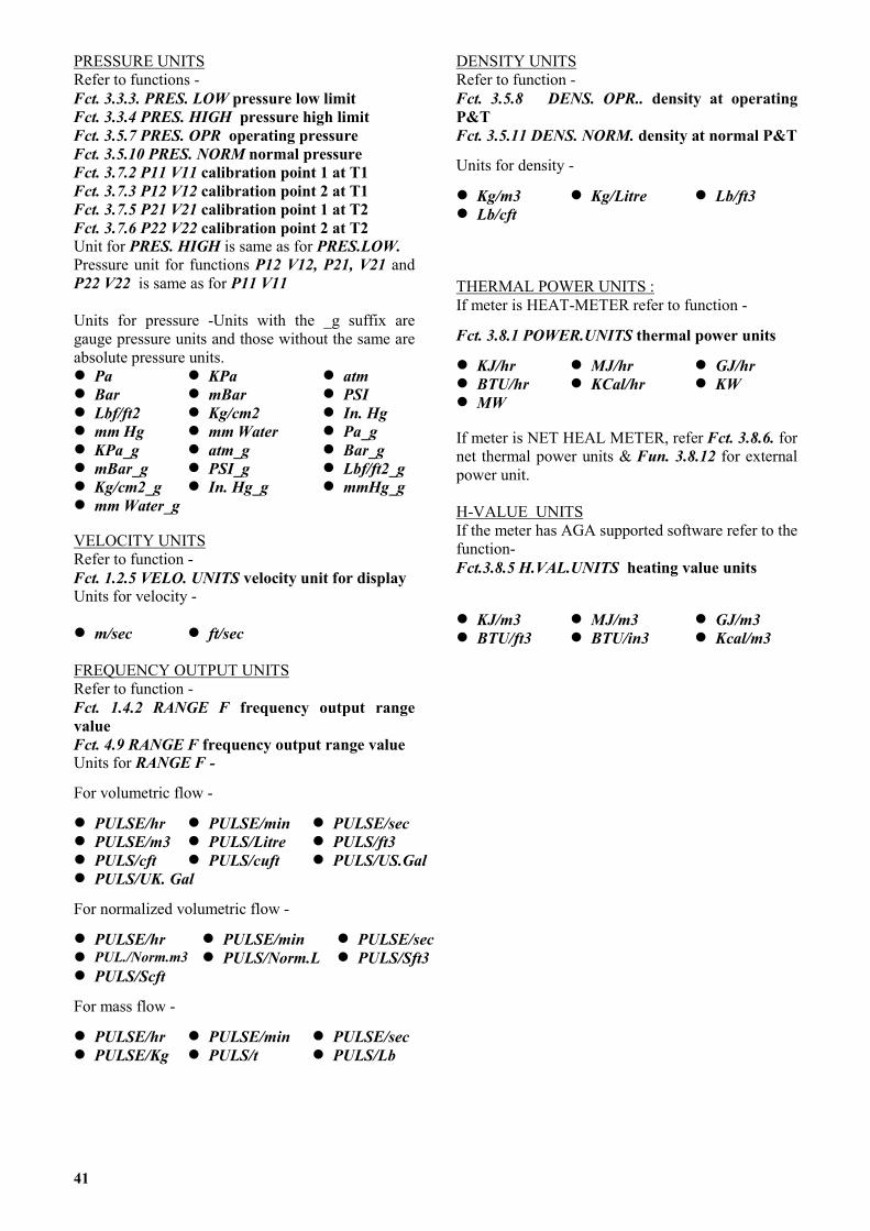
PRESSURE UNITS Refer to functions - Fct. 3.3.3. PRES. LOW pressure low limit Fct. 3.3.4 PRES. HIGH pressure high limit Fct. 3.5.7 PRES. OPR operating pressure Fct. 3.5.10 PRES. NORM normal pressure Fct. 3.7.2 P11 V11 calibration point 1 at T1 Fct. 3.7.3 P12 V12 calibration point 2 at T1 Fct. 3.7.5 P21 V21 calibration point 1 at T2 Fct. 3.7.6 P22 V22 calibration point 2 at T2 Unit for PRES. HIGH is same as for PRES.LOW. Pressure unit for functions P12 V12, P21, V21 and P22 V22 is same as for P11 V11 Units for pressure -Units with the _g suffix are gauge pressure units and those without the same are absolute pressure units. � Pa � KPa � atm � Bar � mBar � PSI � Lbf/ft2 � Kg/cm2 � In. Hg � mm Hg � mm Water � Pa_g � KPa_g � atm_g � Bar_g � mBar_g � PSI_g � Lbf/ft2_g � Kg/cm2_g � In. Hg_g � mmHg_g � mm Water_g VELOCITY UNITS Refer to function - Fct. 1.2.5 VELO. UNITS velocity unit for display Units for velocity - � m/sec � ft/sec FREQUENCY OUTPUT UNITS Refer to function - Fct. 1.4.2 RANGE F frequency output range value Fct. 4.9 RANGE F frequency output range value Units for RANGE F -
For volumetric flow -
� PULSE/hr � PULSE/min � PULSE/sec � PULSE/m3 � PULS/Litre � PULS/ft3 � PULS/cft � PULS/cuft � PULS/US.Gal � PULS/UK. Gal
For normalized volumetric flow -
� PULSE/hr � PULSE/min � PULSE/sec� PUL./Norm.m3 � PULS/Norm.L � PULS/Sft3 � PULS/Scft
For mass flow -
� PULSE/hr � PULSE/min � PULSE/sec � PULSE/Kg � PULS/t � PULS/Lb
DENSITY UNITS Refer to function - Fct. 3.5.8 DENS. OPR.. density at operating P&T Fct. 3.5.11 DENS. NORM. density at normal P&T
Units for density -
� Kg/m3 � Kg/Litre � Lb/ft3 � Lb/cft THERMAL POWER UNITS : If meter is HEAT-METER refer to function -
Fct. 3.8.1 POWER.UNITS thermal power units
� KJ/hr � MJ/hr � GJ/hr � BTU/hr � KCal/hr � KW � MW If meter is NET HEAL METER, refer Fct. 3.8.6. for net thermal power units & Fun. 3.8.12 for external power unit. H-VALUE UNITS If the meter has AGA supported software refer to the function- Fct.3.8.5 H.VAL.UNITS heating value units � KJ/m3 � MJ/m3 � GJ/m3 � BTU/ft3 � BTU/in3 � Kcal/m3
41
�
�
RiFEI(pFa
EaE1P
O
FFF
P
�
�
�
M
P
E
T
6.2.2 Numerical format
Display of numerical values �
�
eal (i.e. fractional) values are displayed in the first line of the display consisting of 8 digits. Number is displayed n floating point format as far as possible, otherwise an exponent notation is used. See examples below. loating format : 1234.5678, 100.00 xponent format : 1234E-10, 12345E12
n most practical applications, it is very rare that parameters need be displayed in exponent format. The precision i.e. number of digits after the decimal point) is automatically decided depending on the unit in which the arameter is being displayed. or example pressure of 1.23456 Bar will be displayed in bar as “1.23” ( 2 digits after decimal point) & in mBar s “1234.6” ( 1 digit after decimal point. Also, note the rounding - off of the last digit).
Input of numerical values
ntering a numeric value is very flexible. Enter a +ve or -ve number in floating point format or exponent format s required or convenient. xample : 1.2345678, -1234.567, 0.0001234 23456E1, -12345E4, 1234E-4 rogramming : refer to section 5.4.
6.2.3 Display
rganisation - Display consists of the following 3 fields.
ield 1 ield 2 ield 3
: : :
Numeric ( 8 digit, 7 segment) used primarily for showing numeric values. alphanumeric (10 characters, 14 segments) used for showing units, messages etc. Consists of [a] 6� markers at the bottom of display which are used to identify the parameter being displayed and [b] key-field at the top left of the display which is used to acknowledge the keys.
rogramming - Measurement mode settings are as follow :
� To allow selection of units for all measured parameters Refer to Sect. 6.1 Fct. 1.2.1 to 1.2.6
� Select what parameters to include in display cycle. Refer to Sect. 6.1 Fct. 1.2.2 to 1.2.6
� Select display mode (cyclic / non-cyclic) and error messages to / not to appear in display cycle. Refer to Sect. 6.1 Fct. 1.2.6 to 1.2.7
easurement mode - Display shows measured parameter(s) in its selected unit. The � markers identify the parameter being displayed. Parameter is displayed continuously in non-cyclic mode. [Refer sect. 6.1 Fct. 1.2.7]. To select other parameter(s) of the display cycle, if any, use the � key. In cyclic mode, all the parameters selected in the display cycle are displayed in sequence one after another every 6 seconds.
rogramming mode - Numeric line indicates menu/functions level such as Fct. 1.0 [current menu level digit “1” blinks] and alphanumeric line indicates menu/function title such as OPERATION.
rror indications - Blinking display in measurements mode indicates that error(s) are present. Error messages are displayed interleaved between changing from one display parameter to other, if Fct. 1.2.6 ERROR.MSG is YES. For description of error messages refer Sect. 5.5.
esting of display - Use Fct. 2.1 TEST DISP for display test. All segments of the display are tested in the following sequence. Alphanumeric field, numeric field, arrow and keymarkers. You can press the E key at any time to terminate display test. Executing display test does not affect the normal operation of the signal converter.
42
6.2.4 Flow range and meter size
Flow rate (min. flow to max. flow) which the flowmeter will be able to measure depends on the primary data (3.1.x functions) and application data (3.5.x functions). thus, the flow range specified under the Fct. 1.1.2 MAX. FLOW and Fct. 1.1.3 MIN. FLOW must be within the measuring range.
Flow range for any given application is determined by sizing of the meter for that application. Refer Sect. 6.1 Fct. 4.5 for details on how the application is sized. The frequency output range value, if programmed in PULSE/time units, directly corresponds to max flow. If flow rate exceeds max flow an error condition HIGH FLOW is generated which may affect current output depending on programming of Fct. 1.3.2 RANGE I. When the flow rate falls below the min. flow an error condition LOW FLOW is generated. Vortex sensor signal is weak at this condition and if flow rate reduces further, vortex signal related errors such as CHECK INST., LOW SIGNAL will occur.
PNfDSc
T
---
-
-
- Np -
-
4
6.2.5 Primary information
rimary data gives VFM 5090(I) the basic information about the vortex primary sensor. Use Fct. 3.1.1 OMINAL.DIA for specification of the nominal DN/ANSI size and Fct. 3.1.2 K-FACTOR for the calibration
actor of the primary. epending on whether the primary has temperature & pressure sensors, settings need be done in Fct. 3.6.1 T-ENSOR and in Fct. 3.6.2 P-SENSOR. These sensors enable VFM 5090(I) to provide online T and/or P ompensation.
6.2.6 Application information
his is the data of process medium, its operating conditions and physical properties. It consists of :
process medium Fct. 3.5.1 FLUID & Fct. 3.5.2 MEDIUM operating temperature and pressure conditions. Refer Fct. 3.5.6 TEMP. OPR and Fct. 3.5.7 PRES. OPR. density of medium at operating conditions. Required only if software within instrument does not support the
medium (Fct. 3.5.2 is selected as -NONE-) Refer Fct. 3.5.8 DENS.OPR.
normal or reference P & T values required for normalized flow measurements only (depending on Fct. 1.1.1).
Usual values are temp.norm = 0 or 20 Deg. C and pres.norm = 1 atm. Refer Fct. 3.5.9 TEMP.NORM and Fct. 3.5.10 PRES.NORM.
density at normal conditions. Required only for normalize volumetric flow and if software within instrument does not support the medium (Fct. 3.5.2 is selected as -NONE-) Refer Fct. 3.5.11 DENS.NORM.
Refer also to Fct. 3.5.3 SAT.P/T which is applicable to saturated steam only.
ot all of the above data need be given for any given application. Only relevant functions appear during actual rogramming.
6.2.7 Internal Electronic Totalizer
The internal electronic totalizer counts volume, normalized- volume or mass. Totalizer value is saved in the non-volatile memory upon power failure. Totalizer can be displayed in the unit desired as per the programming of Fct. 1.2.2 TOTAL.UNITS. Totalizers counting is interrupted for the duration of power failure. Counting may optionally be stopped and thereafter restarted by the use of Fct. 3.2.6 TOT. ON/OFF.
Resetting [to 0] or Setting of the totalizer is possible by using Fct. 3.2.5 TOT. VALUE. If the meter is HEAT METER energy totalizer is provided to store thermal energy. Refer functions 3.8.3 E.TOT.Val and Fct. 3.8.4 E.TOT.ON/OFF. If the meter is NET HEAT METER, one more energy totalizer is provided to store net thermal energy. Refer functions 3.8.8 NT. EN. TOT. VAL and 3.8.9 NE . TOT. ON/OFF. But in this case, only two totalizer out of three (flow, power & net power) can be enabled at a time and not three.
3

6.2.8 Current (analog) output I
Current output gives an analog representation of the flow rate, power and net power also. Programming of current output is provided by 1.3.X functions.
Fct. 1.3.1 FUNCTION I current output function
Choose YES to make current output active as per functions Fct. 1.3.2 to Fct. 1.3.4. NO makes current output inactive (0 mA). When current output function is not required choose the option NO. Fct. 1.3.2 RANGE I current output range selection
Current output can have a 0-20 mA or 4-20 mA range with or without error indication. Flow rates corresponding to I0% [= 0 mA for 0-20 mA ranges and = 4 mA for 4-20 mA ranges] and I100% [= 20 mA for both ranges] are programmable. Refer to figure I-1 for behaviour of current output.
Fct. 1.3.3 0/4mA FLOW and Fct. 1.3.4 20 mA FLOW
Allows to define relationship of current output with respect to the flow rate. Refer to figure I-1 and Sect. 6. Fct. 1.3.5. VARIABLE I Current output selection function You can have current output proporational to any of flow, power and net power. This facility is available if the meter is Heat meter or Net Heat meter only. Since validity of the minimum and maximum values of net heat meter is not checked, please ensure that the value for 20 mA is greater than that for 4/0 mA by a factor of 2. Fct. 1.3.6 0/4 mA POWER and Fct. 1.3.7 20 mA POWER This defines the relationship between current output and power for Heat meter and Net Heat meter. Refer to figure I-1 and sect. 6.
TESTING OF CURRENT OUTPUT I
Fct. 2.2. TEST I can be used to check current output. The following test values are provided 0/2/4/10/20/22 mA to be monitored on a current meter. During the test, current output changes to the test value(s). The normal current value is restored automatically [as per programming of current output] when the testing is over.
CHARACTERISTICS OF CURRENT OUTPUT I
Diagram I-1
6.2.9 Frequency (pulse) output F 44

Frequency output value is directly proportional to the flow rate, power and net power. Programming of frequency output value is provided by 1.4 functions.
Fct. 1.4.1 FUNCTION F frequency output
Choose YES -to make frequency output active as per functions Fct. 1.4.2 to Fct. 1.4.3. NO makes frequency output inactive (0 Hz). When frequency output function is not required choose the option NO.
Fct. 1.4.2 RANGE F frequency output range value
Frequency output is 0 Hz for 0 flow rate and the value programmed in RANGE F for qmax flow rate. [qmax is the maximum flow programmed in Fct. 1.1.2 MAX. FLOW] RANGE F can be programmed in pulse/time units or in the form of pulse/unit flow units. See example below :
Example of pulses/unit flow
Full scale setting, qmax : 1000 Litre/sec (set via Fct. 1.1.2) RANGE F : 1 PULSE/Litre (set via Fct. 1.4.2) at 1000 litres per second : 1000 pulses per second = 1 pulse per litre. Changeover of Full scale setting, qmax : 2000 Litre/sec (set via Fct. 1.1.2) RANGE F : unchanged, 1 PULS/Litre (set via Fct. 1.4.2) at 2000 litres per second : 2000 pulses per second = 1 pulse per litre as before. Example of pulses/time Full scale setting, qmax
:
1000 Litre/sec (set via Fct.1.1.2)
RANGE F : 1000 PULSE/sec (set via Fct.1.4.2) Pulse value is then : 1 pulse per litre Changeover of Full scale setting, qmax
:
2000 Litre/sec (ser via Fct.1.1.2)
RANGE F : unchanged 1000 PULSE/sec (set via Fct. 1.4.2) Pulse value is now : 1 pulse per 2 litres For limits on programming of RANGE F refer to Sect. 6.
Frequency output automatically works in the pulse mode when the following conditions are satisfied
1) fmax evaluates to � 0.5 Hz 2) Internal electronic totalizer is ON. 3) fmax is programmed in pulses/unit flow units. In pulse mode of operation, the pulse output is generated by tracking the totalized flow and thus provides true reflection of internal totalizer value.
Fct. 1.4.3 PULS. WIDTH pulse width
Enables to limit the active duration of frequency output, to reduce the overheating of external electromechanical totalizer coil. Available only when RANGE F evaluates to � 10 Hz. Possible widths to select are - 30 / 50 / 100 / 200 / 500 mSecs. For details refer to Sect. 6. Fct. 1.4.4 VARIABLE F frequency output selection function.
45
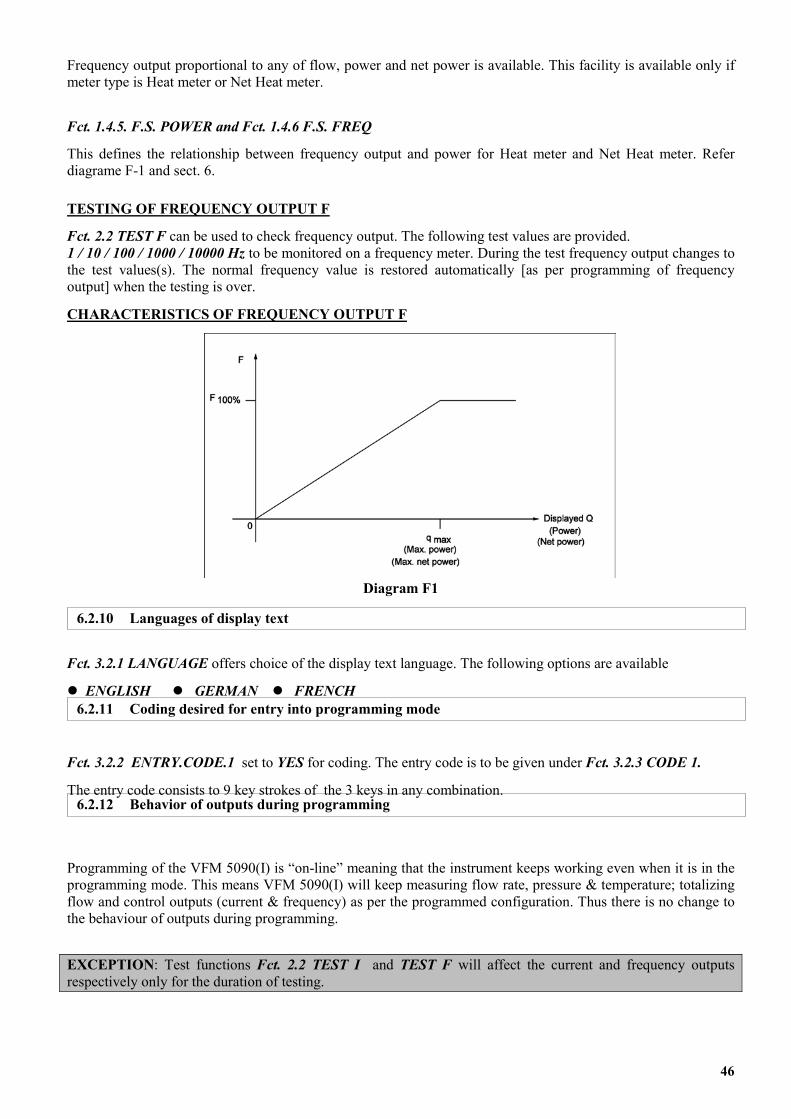
Frequency output proportional to any of flow, power and net power is available. This facility is available only if meter type is Heat meter or Net Heat meter.
Fct. 1.4.5. F.S. POWER and Fct. 1.4.6 F.S. FREQ
This defines the relationship between frequency output and power for Heat meter and Net Heat meter. Refer diagrame F-1 and sect. 6.
TESTING OF FREQUENCY OUTPUT F
Fct. 2.2 TEST F can be used to check frequency output. The following test values are provided. 1 / 10 / 100 / 1000 / 10000 Hz to be monitored on a frequency meter. During the test frequency output changes to the test values(s). The normal frequency value is restored automatically [as per programming of frequency output] when the testing is over.
CHARACTERISTICS OF FREQUENCY OUTPUT F
Diagram F1
Fct. 3.2.1 LANGUAGE offers choice of the display text language. The following options are available
� ENGLISH � GERMAN � FRENCH
Fct. 3.2.2 ENTRY.CODE.1 set to YES for coding. The entry code is to be given under Fct. 3.2.3 CODE 1.
T n any combination.
Ppft
Er
6.2.11 Coding desired for entry into programming mode
6.2.10 Languages of display text
he entry code consists to 9 key strokes of the 3 keys i6.2.12 Behavior of outputs during programming
rogramming of the VFM 5090(I) is “on-line” meaning that the instrument keeps working even when it is in the rogramming mode. This means VFM 5090(I) will keep measuring flow rate, pressure & temperature; totalizing low and control outputs (current & frequency) as per the programmed configuration. Thus there is no change to he behaviour of outputs during programming.
XCEPTION: Test functions Fct. 2.2 TEST I and TEST F will affect the current and frequency outputs espectively only for the duration of testing.
46

s
Part C Function Checks and Trouble Shooting hint7. Functional checks This section describes some functional checks which can be performed without using any special equipment. It must be noted that these checks are very preliminary and do not check the total functionality of the primary head or the signal converter. 7.1 Primary head functional checks
7.1.1 Vortex sensor
To perform preliminary testing of the vortex piezo sensor, the signal cable of the piezo sensor should be disconnected from the signal converter electronics. To do this : always switch-OFF power source before commencing work!
1. Use the special wrench to remove the cover from the electronic compartment. Ensure that screw threads of electronic compartment cover are well greased at all times!
A
Powersupply boardD
D
A
CPU board
Z
Y
X
Preamplifierboard
Flat cableto Displayboard
2. Remove screws A and fold display board to side. 3. Remove the piezo cable from the preamplifier
board at location Z by its connector (and not by pulling cable itself!)
4. Do the following tests.
Capacitance between centre pin and each outer pin.
ANSI DN
3/8” S to 1” 10S to 25
1.5”, 2” 40, 50
3” & above 80 & above
C(nF) 0.8 to 1.5 2.0 to 3.4 2.7 to 4.5
Resistance between centre pin and each outer pin > 200 M ohm. Also resistance between each sensor wire pin and earth should be > 200 M ohm.
5. Re-assemble converter in the reverse order
7.1.2 Temperature Sensor
PT-1000 temperature sensor can be checked by measuring its resistance.
Always switch-OFF power source before commencing work!
Follow the steps 1, 2 same as in the above Section. 7.1.1
3. Remove the temperature sensor cable at location Y of the preamplifier board. Pull cable by its end connector and not by cable itself!
4. Resistance between the 2 pins should be within 1K [00C] - 1.193k [500C] depending on the ambient temperature. For other temperatures resistance values as per DIN43760.
5. Re-assemble converter in the reverse order. 7.2 Signal converter functional checks. 7.2.1 Self diagnostics On power-ON VFC 090 itself carries out diagnostic checks wherein the instrument checks its functional elements as far as possible. Diagnostic failure result in fatal errors and are indication of a hardware fault within electronics. Usually it is necessary to replace electronics in such cases. Meanings of diagnostic error messages are given below for information purpose. Error message Meaning INTL.ERR20 RAM (read/write memory) failed INTL.ERR21 EPROM (program memory) failure INTL.ERR22 GA (Gate Array) failure INTL.ERR23 Interrupt function failure INTL.ERR24 LCD (display) controller failure INTL.ERR25 Timer channel #0 failure INTL.ERR26 Timer channel #1 failure INTL.ERR27 Timer channel #2 failure INTL.ERR28 A/D converter #1 failure INTL.ERR29 A/D converter #2 failure INTL.ERR30 NOVRAM(nonvolatile mem.)failure INTL.ERR31 EEPROM failure INTL.ERR32 UART (Communication controller)
failure INTL.ERR33 KEYS (3 Keys on display board)
problem
47
Display functionality can be checked by the use of Fct. 2.1 TEST DISP.
This function tests all the segments of the display in the following order. Alphanumeric field, numeric field, arrow and key markers. For details refer Sect 5.4 + 6.1.
Fct. 2.2 TEST I can be used to test current output function of VFC 090. With this function it is possible to generate following test values 0/2/4/10/20/22 mA
Current output electronics is factory calibrated and should be within +/- 0.02mA. Otherwise re-calibration of current output is necessary by KHRONE MARSHALL service person.
Fct. 2.3 TEST F is meant for checking frequency output function. The following test frequencies may be generated 1/10/100/1000/10000 Hz. Frequency output signal can be checked on an oscilloscope or a frequency meter between term 4/4.1 and term 4.1/4.2 with a load resistance of 1k to 2k ohms.
It is assumed in this section that the flowmeter has already been installed. (for installation details refer Sect. 2+3)
Following are some trouble shooting hints. SYMPTOM : Display is blank. ��
��
Supply voltage (between term 11/12) is not available. Mains fuse within the instrument has blown out. Fuse is accessible only after removal of electronics from the converter housing. To remove electronics follow the steps given below :
Always switch-OFF power source before commencing work!
1. Use the special wrench to remove the cover from the terminal box.
2. Disconnect all the cables from the terminals : term 5/6/4/4.1/4.2/11/12
3. Use the special wrench to remove the cover from the electronics compartment. (Refer Fig. on page 43)
4. Remove screws A and fold display board to side.
5. Remove plugs X, Y, Z to remove wires from d
pressure sensor, temperature sensor and vortex sensor respectively.
6. Remove screws D using a screwdriver for Philips- head screws [size 2, blade length 200 mm (8”) ] and carefully remove the complete electronics.
7. Remove the fuse from its black plastic housing located on power supply board for checking. Replace the fuse if necessary. Rating of fuse is dependent on line voltage.
7.2.2 Display check
7.2.3 Current output check Voltage Fuse
Value Order No. 220 / 200 / 240 VAC 125 mA K2023937 120 VAC 200 mA K2023938 100 / 110 VAC 250 mA K2023939 8. Reassemble in reverse order
Important : Ensure that the screw thread of the covers on the electronic and connection compartments is well greased at all times. 7.2.4 Frequency output check
Electronics faulty ��
��
��
��
��
��
��
��
��
SYMPTOM : Current output is not proper.
Check current output electronics (refer Sect.7.2.3) Check current output electronics programming of current output functions Fct. 1.3.x.
8. Trouble shooting hints Check that current output loop is not overloaded [700 ohm max.]
SYMPTOM : Freqency output is incorrect
Check the frequency output electronics (refer Sect. 7.2.4) Check programming of frequency output (Functions Fct. 1.4.x.) Check that frequency output is not overloaded. For load ratings of frequency output refer Sect. 3.3.3.
SYMPTOM : Non zero flow indicated when no actual flow in the pipe.
Mains interference due to improper earthing. The protective earth PE terminal should be properly grounded. Excessive mechanical vibration in the pipe. If so, support the pipeline near the flowmeter perpendicular to both the axis of the pipe and the axis of the bluff body.
SYMPTOM : ‘CHECK INST.’ error is displayed when no flow in the pipe
Display should normally indicate 0.0 flow rate, LOW FLOW and LOW SIGNAL errors when there is no
48
flow in the pipe. The additional CHECK INSTALL error (flow rate = 0.0 or some steady or fluctuating value) is an indication of :
improper / inadequate earthing ��
��
��
��
��
��
excessive pipe vibration
SYMPTOM : Flowrate indicated is 0.0 even with flow in the pipe.
Vortex sensor cable disconnected or not properly connected. Flow sensor faulty - some checks are given in Sect. 7.1.1
SYMPTOM : Fatal error INV.CONFIG (invalid configuration)
Configuration data in the non-volatile memory is inadvertently corrupted. Go to the programming mode and recheck (reprogram, if necessary) all the settings. If error persists contact KHRONE MARSHALL service.
SYMPTOM : Display contrast is progressively fading.
Never expose display directly to the sunlight !
��
��
��
��
��
��
��
��
Install a sunshade if necessary.
SYMPTOM : Flow indicated responds to changes in flow but indicated value does not correspond to actual flow rate. Also ‘CHECK INST.’ error may be appearing intermittantly.
Check programming of Fct. 3.1.2 K-Factor which should be same as on the name plate Meter not properly centered on the pipeline The axis of meter bore should be aligned with that of pipe. Gasket at the meter are protruding into pipe bore. Gaskets must not project into effective cross section of the pipe. Irregularities on the surface of the pipe bore. The pipe bore should be free from irregularities at the welded joints, dirt, deposits and excessive surface roughness.
Vortex signal is falsified due to a bi-phase medium. Bi-phase media are not permitted. Use a moisture separator for wet steam applications to remove moisture droplets from the steam. Use suitable filters in gas applications to remove solid particles from the flowing gas. Incorrect angular position of the meter Refer to Sect. 2.1 (I) for allowable mounting positions. Insufficient upstream / downstream pipe lengths. Check that upstream / downstream pipe lengths are of correct minimum length as given in Sect. 2.1 (3). Check the flow direction and direction of arrow on the primary .
49
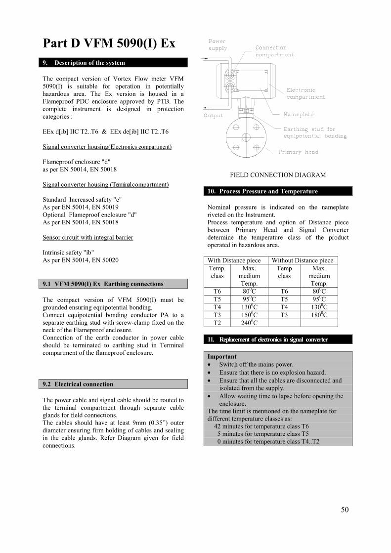
Part D VFM 5090(I) Ex 9. Description of the system The compact version of Vortex Flow meter VFM 5090(I) is suitable for operation in potentially hazardous area. The Ex version is housed in a Flameproof PDC enclosure approved by PTB. The complete instrument is designed in protection categories : EEx d[ib] IIC T2..T6 & EEx de[ib] IIC T2..T6 Signal converter housing(Electronics compartment) Flameproof enclosure "d" as per EN 50014, EN 50018 Signal converter housing (Terminal compartment) Standard Increased safety "e" As per EN 50014, EN 50019 Optional Flameproof enclosure "d" As per EN 50014, EN 50018 Sensor circuit with integral barrier Intrinsic safety "ib" As per EN 50014, EN 50020 9.1 VFM 5090(I) Ex Earthing connections The compact version of VFM 5090(I) must be grounded ensuring equipotential bonding. Connect equipotential bonding conductor PA to a separate earthing stud with screw-clamp fixed on the neck of the Flameproof enclosure. Connection of the earth conductor in power cable should be terminated to earthing stud in Terminal compartment of the flameproof enclosure. 9.2 Electrical connection The power cable and signal cable should be routed to the terminal compartment through separate cable glands for field connections. The cables should have at least 9mm (0.35”) outer diameter ensuring firm holding of cables and sealing in the cable glands. Refer Diagram given for field connections.
FIELD CONNECTION DIAGRAM 10. Process Pressure and Temperature Nominal pressure is indicated on the nameplate riveted on the Instrument. Process temperature and option of Distance piece between Primary Head and Signal Converter determine the temperature class of the product operated in hazardous area. With Distance piece Without Distance piece Temp. class
Max. medium Temp.
Temp class
Max. medium Temp.
T6 800C T6 800C T5 950C T5 950C T4 1300C T4 1300C T3 1500C T3 1800C T2 2400C
11. Replacement of electronics in signal converter Important �� Switch off the mains power. �� Ensure that there is no explosion hazard. �� Ensure that all the cables are disconnected and
isolated from the supply. �� Allow waiting time to lapse before opening the
enclosure. The time limit is mentioned on the nameplate for different temperature classes as: 42 minutes for temperature class T6 5 minutes for temperature class T5 0 minutes for temperature class T4..T2
50

Make sure that precautions as mentioned above, are taken as Important and observe the sequence as follows: 1. Use special wrench to remove window cover. 2. Remove screws A to fold Display assembly to
one side. 3. Remove signal cables from latched connectors
Y,Z,X (2,3,5 pin) on Barrier board assembly. 4. Unscrew the mounting screws D. 5. Pull the unit out holding the montage holder. 6. Replace the unit in reverse order, from 5 to1. Caution �� Ensure that the earthing platelet on barrier board
is firmly connected to the enclosure by screw SE.
�� Ensure that the Window cover is screwed down firmly so that it cannot be opened by hand.
�� Ensure that the sensor cables are properly latched to y,z,x (2,3,5 pin) connectors on barrier board.
�� Ensure that the gaskets on the covers of the enclosure are properly in place.
12. Certificate No. of VFM 5090(I) Ex: FM, CSA, PTB approvals are pending.
51


13. Nameplates of VFM 5090(I)Ex
51 52
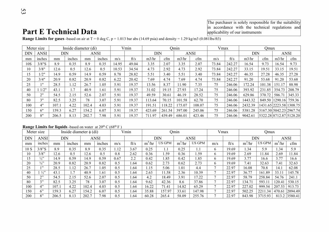
53
Part E Technical Data The purchaser is solely responsible for the suitability in accordance with the technical regulations and applicability of our instruments
Range Limits for gases -based on air at T = 0 deg C, p = 1.013 bar abs (14.69 psia) and density = 1.29 kg/m3 (0.081lbs/ft3)
Meter size Inside diameter (di) Vmin Qmin Vmax QmaxDIN ANSI DIN ANSI DIN ANSI DIN ANSImm inches mm inches mm inches m/s ft/s m3/hr cfm m3/hr cfm m/s ft/s m3/hr cfm m3/hr cfm10S 3/8"S 8.9 0.35 8.9 0.35 14.95 49.04 3.35 2.07 3.35 2.07 73.84 242.27 16.54 9.73 16.54 9.7310 3/8" 12.6 0.5 12.6 0.5 10.53 34.54 4.73 2.92 4.73 2.92 73.84 242.27 33.15 19.51 33.15 19.5115 1/2" 14.9 0.59 14.9 0.59 8.78 28.82 5.51 3.40 5.51 3.40 73.84 242.27 46.35 27.28 46.35 27.2820 3/4" 20.9 0.82 20.9 0.82 6.22 20.42 7.69 4.74 7.69 4.74 73.84 242.27 91.20 53.68 91.20 53.6825 1" 28.5 1.12 26.7 1.05 5.91 19.37 13.56 8.37 11.90 7.35 75 246.06 172.24 101.38 151.17 88.9840 1 1/2" 43.1 1.7 40.9 1.61 5.91 19.37 31.02 19.15 27.93 17.24 75 246.06 393.92 231.85 354.73 208.7950 2" 54.5 2.15 52.6 2.07 5.91 19.37 49.59 30.61 46.19 28.52 75 246.06 629.86 370.72 586.71 345.3380 3" 82.5 3.25 78 3.07 5.91 19.37 113.64 70.15 101.58 62.70 75 246.06 1443.32 849.50 1290.16 759.36
100 4" 107.1 4.22 102.4 4.03 5.91 19.37 191.51 118.22 175.07 108.07 75 246.06 2432.39 1431.65 2223.58 1308.75150 6" 159.3 6.27 154.2 6.07 5.91 19.37 423.69 261.54 397.00 245.06 75 246.06 5381.28 3167.30 5042.23 2967.74200 8" 206.5 8.13 202.7 7.98 5.91 19.37 711.97 439.49 686.01 423.46 75 246.06 9042.61 5322.28 8712.87 5128.20
Range Limits for liquids -based on water at 20o C (68o F )
Meter size Inside diameter � (di) Vmin Qmin Vmax Qmax DIN ANSI DIN ANSI DIN ANSI DIN ANSImm inches mm inches mm inches m/s ft/s m3/hr US GPM m3/hr US GPM m/s ft/s m3/hr US GPM m3/hr cfm10 S 3/8”S 8.9 0.35 8.9 0.35 1.12 3.67 0.25 1.1 0.25 1.1 6 19.69 1.34 5.9 1.34 5.910 3/8” 12.6 0.5 12.6 0.5 0.8 2.62 0.36 1.59 0.36 1.59 6 19.69 2.69 11.84 2.69 11.8415 ½” 14.9 0.59 14.9 0.59 0.67 2.2 0.42 1.85 0.42 1.85 6 19.69 3.77 16.6 3.77 16.620 ¾” 20.9 0.82 20.9 0.82 0.5 1.64 0.62 2.73 0.62 2.73 6 19.69 7.41 32.63 7.41 32.6325 1” 28.5 1.12 26.7 1.05 0.5 1.64 1.15 5.06 1.01 4.4 7 22.97 16.08 70.8 14.1 62.0840 1 ½” 43.1 1.7 40.9 1.61 0.5 1.64 2.63 11.58 2.36 10.39 7 22.97 36.77 161.89 33.11 145.7850 2” 54.5 2.15 52.6 2.07 0.5 1.64 4.2 18.49 3.91 17.22 7 22.97 58.79 258.84 54.76 241.180 3” 82.5 3.25 78 3.07 0.5 1.64 9.62 42.36 8.6 37.86 7 22.97 134.71 593.11 120.41 530.15
100 4” 107.1 4.22 102.4 4.03 0.5 1.64 16.22 71.41 14.82 65.29 7 22.97 227.02 999.54 207.53 913.73150 6” 159.3 6.27 154.2 6.07 0.5 1.64 35.88 157.97 33.61 147.98 7 22.97 502.25 2211.34 470.61 2094.49200 8” 206.5 8.13 202.7 7.98 0.5 1.64 60.28 265.4 58.09 255.76 7 22.97 843.98 3715.93 813.2 3580.41
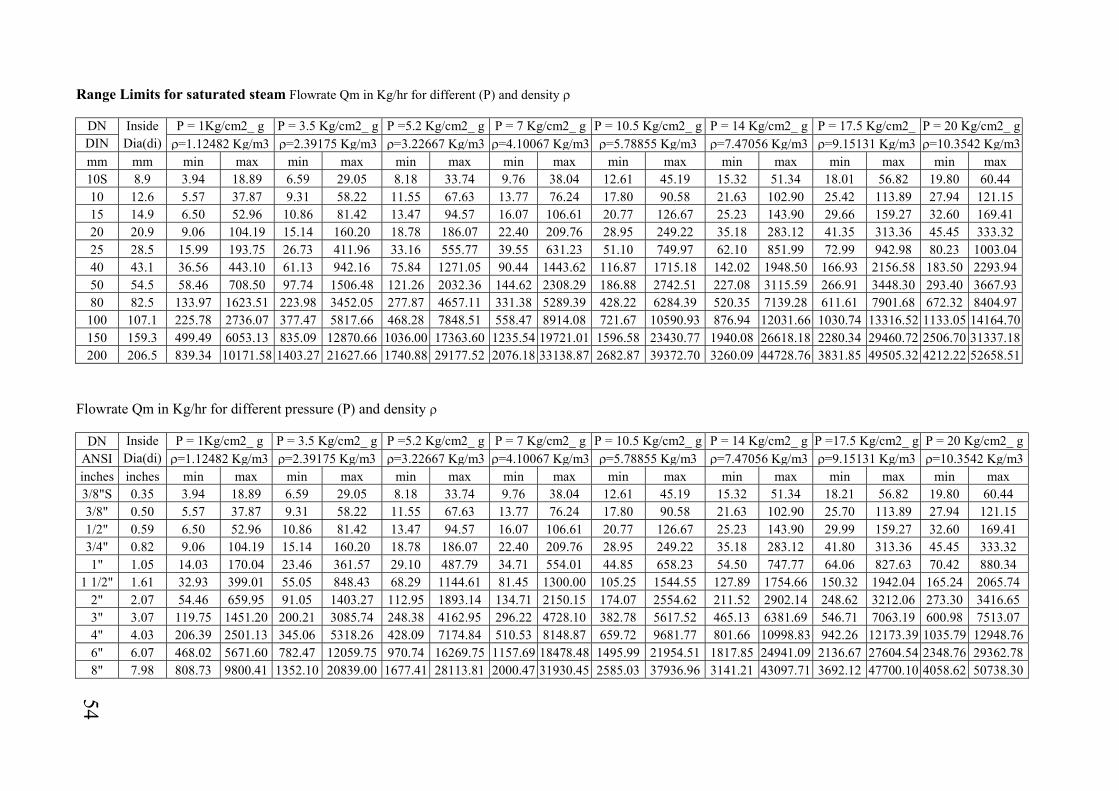
Range Limits for saturated steam Flowrate Qm in Kg/hr for different (P) and density �
DN Inside P = 1Kg/cm2_ g P = 3.5 Kg/cm2_ g P =5.2 Kg/cm2_ g P = 7 Kg/cm2_ g P = 10.5 Kg/cm2_ g P = 14 Kg/cm2_ g P = 17.5 Kg/cm2_ P = 20 Kg/cm2_ g DIN Dia(di) �=1.12482 Kg/m3 �=2.39175 Kg/m3 �=3.22667 Kg/m3 �=4.10067 Kg/m3 �=5.78855 Kg/m3 �=7.47056 Kg/m3 �=9.15131 Kg/m3 �=10.3542 Kg/m3 mm mm min max min max min max min max min max min max min max min max10S 8.9 3.94 18.89 6.59 29.05 8.18 33.74 9.76 38.04 12.61 45.19 15.32 51.34 18.01 56.82 19.80 60.4410 12.6 5.57 37.87 9.31 58.22 11.55 67.63 13.77 76.24 17.80 90.58 21.63 102.90 25.42 113.89 27.94 121.1515 14.9 6.50 52.96 10.86 81.42 13.47 94.57 16.07 106.61 20.77 126.67 25.23 143.90 29.66 159.27 32.60 169.4120 20.9 9.06 104.19 15.14 160.20 18.78 186.07 22.40 209.76 28.95 249.22 35.18 283.12 41.35 313.36 45.45 333.3225 28.5 15.99 193.75 26.73 411.96 33.16 555.77 39.55 631.23 51.10 749.97 62.10 851.99 72.99 942.98 80.23 1003.0440 43.1 36.56 443.10 61.13 942.16 75.84 1271.05 90.44 1443.62 116.87 1715.18 142.02 1948.50 166.93 2156.58 183.50 2293.9450 54.5 58.46 708.50 97.74 1506.48 121.26 2032.36 144.62 2308.29 186.88 2742.51 227.08 3115.59 266.91 3448.30 293.40 3667.9380 82.5 133.97 1623.51 223.98 3452.05 277.87 4657.11 331.38 5289.39 428.22 6284.39 520.35 7139.28 611.61 7901.68 672.32 8404.97
100 107.1 225.78 2736.07 377.47 5817.66 468.28 7848.51 558.47 8914.08 721.67 10590.93 876.94 12031.66 1030.74 13316.52 1133.05 14164.70 150 159.3 499.49 6053.13 835.09 12870.66 1036.00 17363.60 1235.54 19721.01 1596.58 23430.77 1940.08 26618.18 2280.34 29460.72 2506.70 31337.18 200 206.5 839.34 10171.58 1403.27 21627.66 1740.88 29177.52 2076.18 33138.87 2682.87 39372.70 3260.09 44728.76 3831.85 49505.32 4212.22 52658.51
Flowrate Qm in Kg/hr for different pressure (P) and density �
DN Inside P = 1Kg/cm2_ g P = 3.5 Kg/cm2_ g P =5.2 Kg/cm2_ g P = 7 Kg/cm2_ g P = 10.5 Kg/cm2_ g P = 14 Kg/cm2_ g P =17.5 Kg/cm2_ g P = 20 Kg/cm2_ g ANSI Dia(di) �=1.12482 Kg/m3 �=2.39175 Kg/m3 �=3.22667 Kg/m3 �=4.10067 Kg/m3 �=5.78855 Kg/m3 �=7.47056 Kg/m3 �=9.15131 Kg/m3 �=10.3542 Kg/m3 inches inches min max min max min max min max min max min max min max min max3/8"S 0.35 3.94 18.89 6.59 29.05 8.18 33.74 9.76 38.04 12.61 45.19 15.32 51.34 18.21 56.82 19.80 60.443/8" 0.50 5.57 37.87 9.31 58.22 11.55 67.63 13.77 76.24 17.80 90.58 21.63 102.90 25.70 113.89 27.94 121.151/2" 0.59 6.50 52.96 10.86 81.42 13.47 94.57 16.07 106.61 20.77 126.67 25.23 143.90 29.99 159.27 32.60 169.413/4" 0.82 9.06 104.19 15.14 160.20 18.78 186.07 22.40 209.76 28.95 249.22 35.18 283.12 41.80 313.36 45.45 333.321" 1.05 14.03 170.04 23.46 361.57 29.10 487.79 34.71 554.01 44.85 658.23 54.50 747.77 64.06 827.63 70.42 880.34
1 1/2" 1.61 32.93 399.01 55.05 848.43 68.29 1144.61 81.45 1300.00 105.25 1544.55 127.89 1754.66 150.32 1942.04 165.24 2065.742" 2.07 54.46 659.95 91.05 1403.27 112.95 1893.14 134.71 2150.15 174.07 2554.62 211.52 2902.14 248.62 3212.06 273.30 3416.653" 3.07 119.75 1451.20 200.21 3085.74 248.38 4162.95 296.22 4728.10 382.78 5617.52 465.13 6381.69 546.71 7063.19 600.98 7513.074" 4.03 206.39 2501.13 345.06 5318.26 428.09 7174.84 510.53 8148.87 659.72 9681.77 801.66 10998.83 942.26 12173.39 1035.79 12948.766" 6.07 468.02 5671.60 782.47 12059.75 970.74 16269.75 1157.69 18478.48 1495.99 21954.51 1817.85 24941.09 2136.67 27604.54 2348.76 29362.78 8" 7.98 808.73 9800.41 1352.10 20839.00 1677.41 28113.81 2000.47 31930.45 2585.03 37936.96 3141.21 43097.71 3692.12 47700.10 4058.62 50738.30
54
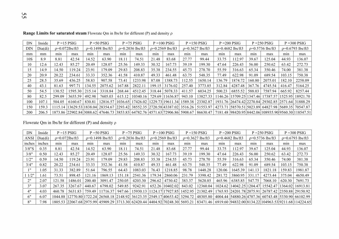
Range Limits for saturated steam Flowrate Qm in lbs/hr for different (P) and density �
DN Inside P =15 PSIG P =50 PSIG P =75 PSIG P =100 PSIG P =150 PSIG P =200 PSIG P =250 PSIG P =300 PSIG DIN Dia(di) �=0.072lbs/ft3 �=0.1498 lbs/ft3 �=0.2036 lbs/ft3 �=0.2569 lbs/ft3 �=0.3627 lbs/ft3 �=0.4682 lbs/ft3 �=0.5736 lbs/ft3 �=0.6793 lbs/ft3 mm mm min max min max min max min max min max min max min max min max10S 8.9 8.81 42.54 14.52 63.90 18.11 74.51 21.48 83.68 27.77 99.44 33.75 112.97 39.67 125.04 44.93 136.0710 12.6 12.43 85.27 20.49 128.07 25.56 149.33 30.32 167.73 39.19 199.30 47.64 226.43 56.00 250.62 63.42 272.7315 14.9 14.50 119.24 23.91 179.09 29.83 208.83 35.38 234.55 45.73 278.70 55.59 316.63 65.34 350.46 74.00 381.3820 20.9 20.22 234.61 33.33 352.36 41.58 410.87 49.33 461.48 63.75 548.35 77.49 622.98 91.09 689.54 103.15 750.3825 28.5 35.69 436.25 58.83 907.58 73.41 1233.98 87.08 1388.73 112.55 1650.14 136.79 1874.72 160.80 2075.01 182.10 2258.0940 43.1 81.63 997.71 134.55 2075.62 167.88 2822.11 199.15 3176.02 257.40 3773.85 312.84 4287.48 367.76 4745.54 416.47 5164.2550 54.5 130.52 1595.30 215.14 3318.84 268.44 4512.45 318.44 5078.33 411.57 6034.25 500.23 6855.52 588.03 7587.94 665.92 8257.4480 82.5 299.09 3655.59 492.98 7605.03 615.12 10340.16 729.69 11636.87 943.10 13827.33 1146.26 15709.25 1347.46 17387.57 1525.95 18921.70
100 107.1 504.05 6160.67 830.81 12816.57 1036.65 17426.02 1229.73 19611.34 1589.38 23302.87 1931.76 26474.42 2270.84 29302.85 2571.64 31888.29 150 159.3 1115.14 13629.53 1838.04 28354.67 2293.42 38552.35 2720.58 43387.02 3516.26 51553.97 4273.71 58570.51 5023.89 64827.98 5689.35 70547.87 200 206.5 1873.86 22902.84 3088.62 47646.73 3853.83 64782.76 4571.63 72906.86 5908.67 86630.47 7181.48 98420.95 8442.06 108935.90 9560.30 118547.51
Flowrate Qm in lbs/hr for different (P) and density �
DN Inside P =15 PSIG P =50 PSIG P =75 PSIG P =100 PSIG P =150 PSIG P =200 PSIG P =250 PSIG P =300 PSIG ANSI Dia(di) �=0.072lbs/ft3 �=0.1498 lbs/ft3 �=0.2036 lbs/ft3 �=0.2569 lbs/ft3 �=0.3627 lbs/ft3 �=0.4682 lbs/ft3 �=0.5736 lbs/ft3 �=0.6793 lbs/ft3 inches inches min max min max min max min max min max min max min max min max3/8"S 0.35 8.81 42.54 14.52 63.90 18.11 74.51 21.48 83.68 27.77 99.44 33.75 112.97 39.67 125.04 44.93 136.073/8" 0.50 12.43 85.27 20.49 128.07 25.56 149.33 30.32 167.73 39.19 199.30 47.64 226.43 56.00 250.62 63.42 272.731/2" 0.59 14.50 119.24 23.91 179.09 29.83 208.83 35.38 234.55 45.73 278.70 55.59 316.63 65.34 350.46 74.00 381.383/4" 0.82 20.22 234.61 33.33 352.36 41.58 410.87 49.33 461.48 63.75 548.35 77.49 622.98 91.09 689.54 103.15 750.381" 1.05 31.33 382.89 51.64 796.55 64.43 1083.03 76.43 1218.85 98.78 1448.28 120.06 1645.39 141.13 1821.18 159.83 1981.87
1 1/2" 1.61 73.51 898.45 121.16 1869.13 151.18 2541.36 179.34 2860.06 231.79 3398.42 281.72 3860.95 331.17 4273.44 375.04 4650.492" 2.07 121.58 1486.01 200.40 3091.47 250.05 4203.30 296.62 4730.42 383.37 5620.85 465.96 6385.85 547.75 7068.10 620.30 7691.733" 3.07 267.35 3267.67 440.67 6798.02 549.85 9242.91 652.26 10402.02 843.02 12360.04 1024.62 14042.25 1204.47 15542.47 1364.02 16913.814" 4.03 460.78 5631.83 759.49 11716.37 947.66 15930.13 1124.17 17927.85 1452.95 21302.49 1765.93 24201.78 2075.91 26787.42 2350.88 29150.92 6" 6.07 1044.88 12770.80 1722.24 26568.18 2148.92 36123.35 2549.17 40653.42 3294.72 48305.80 4004.44 54880.26 4707.36 60743.48 5330.90 66102.99 8" 7.98 1805.53 22067.68 2975.99 45909.29 3713.30 62420.44 4404.92 70248.30 5693.21 83471.46 6919.60 94832.00 8134.22 104963.53 9211.68 114224.65
55
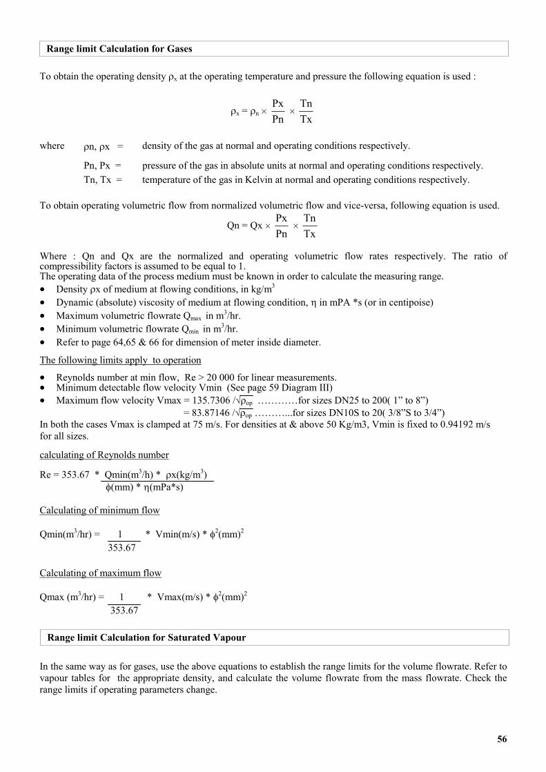
Range limit Calculation for Gases
To obtain the operating density �x at the operating temperature and pressure the following equation is used :
�x = �n � PnPx
� TxTn
where �n, �x = density of the gas at normal and operating conditions respectively.
Pn, Px = pressure of the gas in absolute units at normal and operating conditions respectively. Tn, Tx = temperature of the gas in Kelvin at normal and operating conditions respectively. To obtain operating volumetric flow from normalized volumetric flow and vice-versa, following equation is used.
Qn = Qx � PnPx
� TxTn
Where : Qn and Qx are the normalized and operating volumetric flow rates respectively. The ratio of compressibility factors is assumed to be equal to 1. The operating data of the process medium must be known in order to calculate the measuring range.
Density �x of medium at flowing conditions, in kg/m3 ��
��
��
��
��
Dynamic (absolute) viscosity of medium at flowing condition, � in mPA *s (or in centipoise) Maximum volumetric flowrate Qmax in m3/hr. Minimum volumetric flowrate Qmin in m3/hr. Refer to page 64,65 & 66 for dimension of meter inside diameter.
The following limits apply to operation
Reynolds number at min flow, Re > 20 000 for linear measurements. ��
��
��
Minimum detectable flow velocity Vmin (See page 59 Diagram III) Maximum flow velocity Vmax = 135.7306 /��op …………for sizes DN25 to 200( 1” to 8”)
= 83.87146 /��op ………...for sizes DN10S to 20( 3/8”S to 3/4”) In both the cases Vmax is clamped at 75 m/s. For densities at & above 50 Kg/m3, Vmin is fixed to 0.94192 m/s for all sizes.
calculating of Reynolds number
Re = 353.67 * Qmin(m3/h) * �x(kg/m3) �(mm) * �(mPa*s) Calculating of minimum flow Qmin(m3/hr) = 1 * Vmin(m/s) * �2(mm)2
353.67 Calculating of maximum flow Qmax (m3/hr) = 1 * Vmax(m/s) * �2(mm)2
353.67
Range limit Calculation for Saturated Vapour
In the same way as for gases, use the above equations to establish the range limits for the volume flowrate. Refer to vapour tables for the appropriate density, and calculate the volume flowrate from the mass flowrate. Check the range limits if operating parameters change.
56
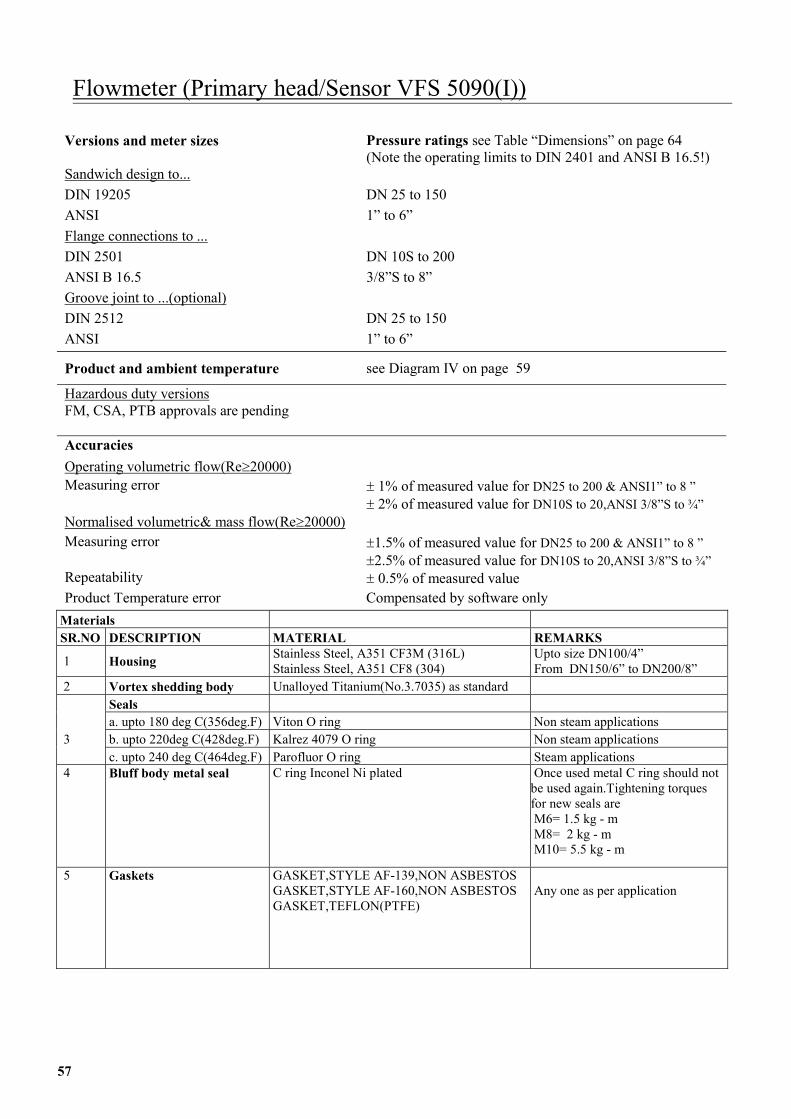
M S
1
2 3 4
5
5
Flowmeter (Primary head/Sensor VFS 5090(I))
Versions and meter sizes Pressure ratings see Table “Dimensions” on page 64 (Note the operating limits to DIN 2401 and ANSI B 16.5!)
Sandwich design to... DIN 19205 DN 25 to 150 ANSI 1” to 6” Flange connections to ... DIN 2501 DN 10S to 200 ANSI B 16.5 3/8”S to 8” Groove joint to ...(optional) DIN 2512 DN 25 to 150 ANSI 1” to 6”
Product and ambient temperature see Diagram IV on page 59
Hazardous duty versions FM, CSA, PTB approvals are pending Accuracies Operating volumetric flow(Re�20000) Measuring error � 1% of measured value for DN25 to 200 & ANSI1” to 8 ”
� 2% of measured value for DN10S to 20,ANSI 3/8”S to ¾” Normalised volumetric& mass flow(Re�20000) Measuring error �1.5% of measured value for DN25 to 200 & ANSI1” to 8 ”
�2.5% of measured value for DN10S to 20,ANSI 3/8”S to ¾” Repeatability � 0.5% of measured value Product Temperature error Compensated by software only
aterials R.NO DESCRIPTION MATERIAL REMARKS
Housing Stainless Steel, A351 CF3M (316L) Stainless Steel, A351 CF8 (304)
Upto size DN100/4” From DN150/6” to DN200/8”
Vortex shedding body Unalloyed Titanium(No.3.7035) as standard Seals
a. upto 180 deg C(356deg.F) Viton O ring Non steam applications b. upto 220deg C(428deg.F) Kalrez 4079 O ring Non steam applications
c. upto 240 deg C(464deg.F) Parofluor O ring Steam applications Bluff body metal seal C ring Inconel Ni plated Once used metal C ring should not
be used again.Tightening torques for new seals are M6= 1.5 kg - m M8= 2 kg - m M10= 5.5 kg - m
Gaskets GASKET,STYLE AF-139,NON ASBESTOS GASKET,STYLE AF-160,NON ASBESTOS GASKET,TEFLON(PTFE)
Any one as per application
7
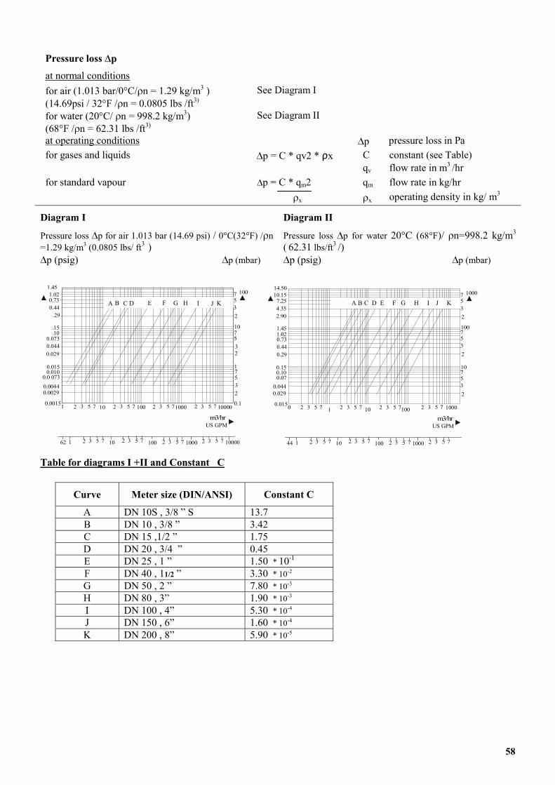
Pressure loss �p
at normal conditions for air (1.013 bar/0�C/�n = 1.29 kg/m3 ) (14.69psi / 32�F /�n = 0.0805 lbs /ft3)
See Diagram I
for water (20�C/ �n = 998.2 kg/m3) (68�F /�n = 62.31 lbs /ft3)
See Diagram II
at operating conditions �p pressure loss in Pa for gases and liquids �p = C * qv2 * ρx C constant (see Table) qv flow rate in m3 /hr for standard vapour �p = C * qm2 qm flow rate in kg/hr �x �x operating density in kg/ m3
Diagram I
Pressure loss �p for air 1.013 bar (14.69 psi) / 0�C(32�F) /�n =1.29 kg/m3 (0.0805 lbs/ ft3 ) �p (psig) �p (mbar)
Diagram II
Pressure loss �p for water 20�C (68�F)/ �n=998.2 kg/m3
( 62.31 lbs/ft3 /) �p (psig) �p (mbar)
7532
7532
7532
10
1
A B C D E F G H I J K
2 3 5 7 10 2 3 5 7 100 2 3 5 71000 2 0.13 5 7 100001
1.020.730.44
.29
.15
.100.0730.0440.029
0.0150.010
0.0 0730.00440.0029
0.0015
1.45100
62 1 10 100 1000 100002 3 5 7 2 3 5 7 2 3 5 7 2 3 5 7
m /hUS GPM
3
7532
7532
7532
100
10
A B C D E F G H I J K
2 3 5 7 1 2 3 5 7 10 2 3 5 7100 2 3 5 7 10000
10.157.254.352.90
1.451.020.730.440.29
0.150.100.07
0.0440.029
0.015
14.501000
44 1 10 100 10002 3 5 7 2 3 5 7 2 3 5 7 2 3 5 7
m /hUS GPM
3m3/hrm3/hr
Table for diagrams I +II and Constant C
Curve Meter size (DIN/ANSI) Constant C
A DN 10S , 3/8 ” S 13.7 B DN 10 , 3/8 ” 3.42 C DN 15 ,1/2 ” 1.75 D DN 20 , 3/4 ” 0.45 E DN 25 , 1 ” 1.50 * 10-1 F DN 40 , 11/2 ” 3.30 * 10-2 G DN 50 , 2 ” 7.80 * 10-3 H DN 80 , 3” 1.90 * 10-3 I DN 100 , 4” 5.30 * 10-4 J DN 150 , 6” 1.60 * 10-4 K DN 200 , 8” 5.90 * 10-5
58
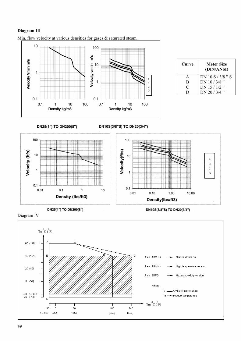
Diagram III Min. flow velocity at various densities for gases & saturated steam.
59
0.1
1
10
0.1 1 10 100Density kg/m3
Velo
city
Vm
in m
/s
0.1
1
10
100
0.1 1 10 100Density kg/m3
Velo
city
vm
in m
/s
ABCD
Curve Meter Size (DIN/ANSI)
A B C D
DN 10 S / 3/8 ” S DN 10 / 3/8 ” DN 15 / 1/2 ” DN 20 / 3/4 ”
DN10S(3/8"S) TO DN20(3/4")DN25(1") TO DN200(8")
Diagram IV
Tm 0C (
0F)
Tu 0C (
0F)
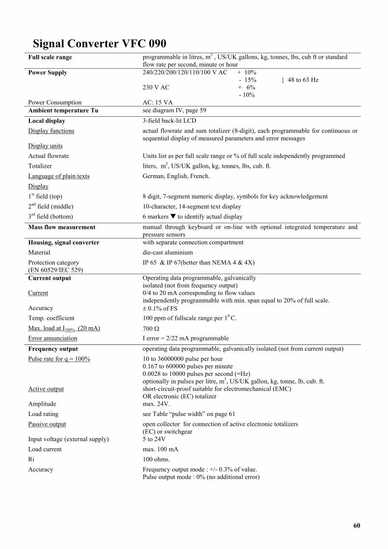
0
Fu
Po PoALoD
DAToLaD1s
2n
3r
M
HMPr(EC
Cu
ATeMErFrPu
A
ALoPa
InLoRiA
Signal Converter VFC 09
ll scale range programmable in litres, m3 , US/UK gallons, kg, tonnes, lbs, cub ft or standardflow rate per second, minute or hour
wer Supply
wer Consumption
240/220/200/120/110/100 V AC + 10% - 15% 230 V AC + 6% - 10% AC: 15 VA
} 48 to 63 Hz
mbient temperature Tu see diagram IV, page 59 cal display 3-field back-lit LCD
isplay functions actual flowrate and sum totalizer (8-digit), each programmable for continuous or sequential display of measured parameters and error messages
isplay units ctual flowrate Units list as per full scale range or % of full scale independently programmed talizer liters, m3, US/UK gallon, kg, tonnes, lbs, cub. ft. nguage of plain texts German, English, French.
isplay t field (top) 8 digit, 7-segment numeric display, symbols for key acknowledgement d field (middle) 10-character, 14-segment text display d field (bottom) 6 markers � to identify actual display ass flow measurement manual through keyboard or on-line with optional integrated temperature and
pressure sensors ousing, signal converter with separate connection compartment aterial die-cast aluminium otection category N 60529/IEC 529)
IP 65 & IP 67(better than NEMA 4 & 4X)
urrent output Operating data programmable, galvanically isolated (not from frequency output)
rrent 0/4 to 20 mA corresponding to flow values independently programmable with min. span equal to 20% of full scale.
ccuracy � 0.1% of FS mp. coefficient 100 ppm of fullscale range per 10 C.
ax. load at I100% (20 mA) 700 � ror annunciation I error = 2/22 mA programmable equency output operating data programmable, galvanically isolated (not from current output) lse rate for q = 100% 10 to 36000000 pulse per hour
0.167 to 600000 pulses per minute 0.0028 to 10000 pulses per second (=Hz) optionally in pulses per litre, m3, US/UK gallon, kg, tonne, lb, cub. ft.
ctive output short-circuit-proof suitable for electromechanical (EMC) OR electronic (EC) totalizer
mplitude max. 24V. ad rating see Table “pulse width” on page 61 ssive output open collector for connection of active electronic totalizers
(EC) or switchgear put voltage (external supply) 5 to 24V ad current max. 100 mA 100 ohms. ccuracy Frequency output mode : +/- 0.3% of value.
Pulse output mode : 0% (no additional error)
60
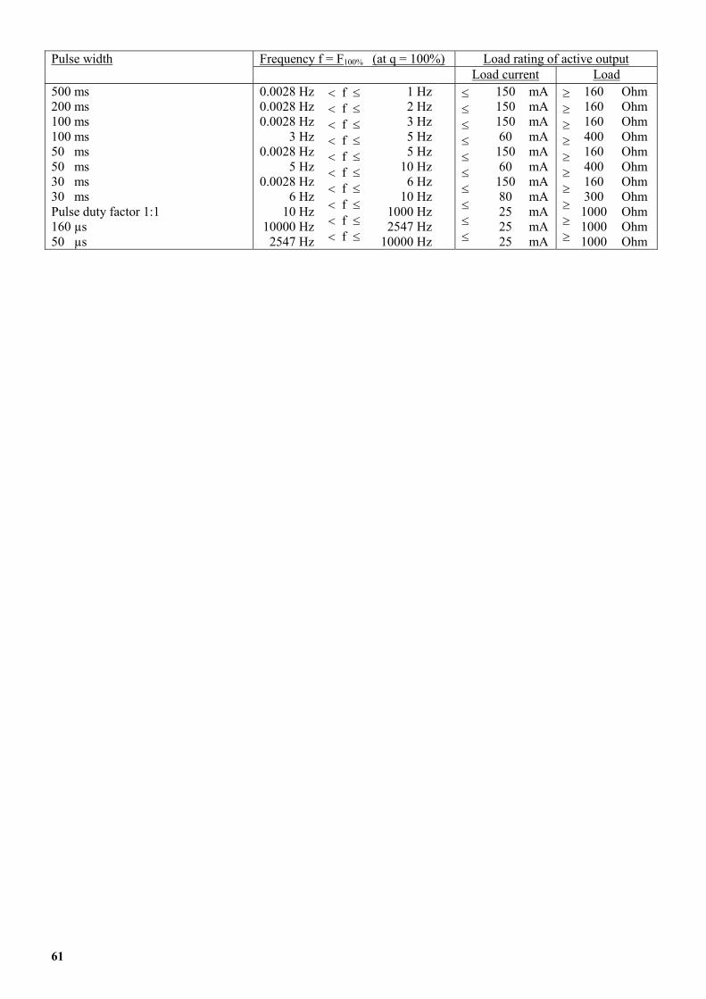
Frequency f = F100% (at q = 100%) Load rating of active output Pulse width Load current Load 500 ms 200 ms 100 ms 100 ms 50 ms 50 ms 30 ms 30 ms Pulse duty factor 1:1 160 µs 50 µs
0.0028 Hz 0.0028 Hz 0.0028 Hz
3 Hz 0.0028 Hz
5 Hz 0.0028 Hz
6 Hz 10 Hz
10000 Hz 2547 Hz
� f � � f � � f � � f � � f � � f � � f � � f � � f � � f �
1 Hz 2 Hz 3 Hz 5 Hz 5 Hz
10 Hz 6 Hz
10 Hz 1000 Hz 2547 Hz
10000 Hz
� � � � � � � � � �
150 150 150 60 150 60 150 80 25 25 25
mA mA mA mA mA mA mA mA mA mA mA
� � � � � � � � � �
160 160 160 400 160 400 160 300
1000 1000 1000
Ohm Ohm Ohm Ohm Ohm Ohm Ohm Ohm Ohm Ohm Ohm
61
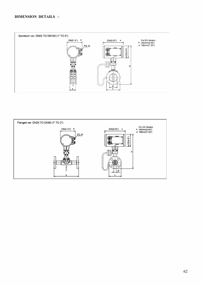
DIMENSION�DETAILS :- �
���������
������������
62
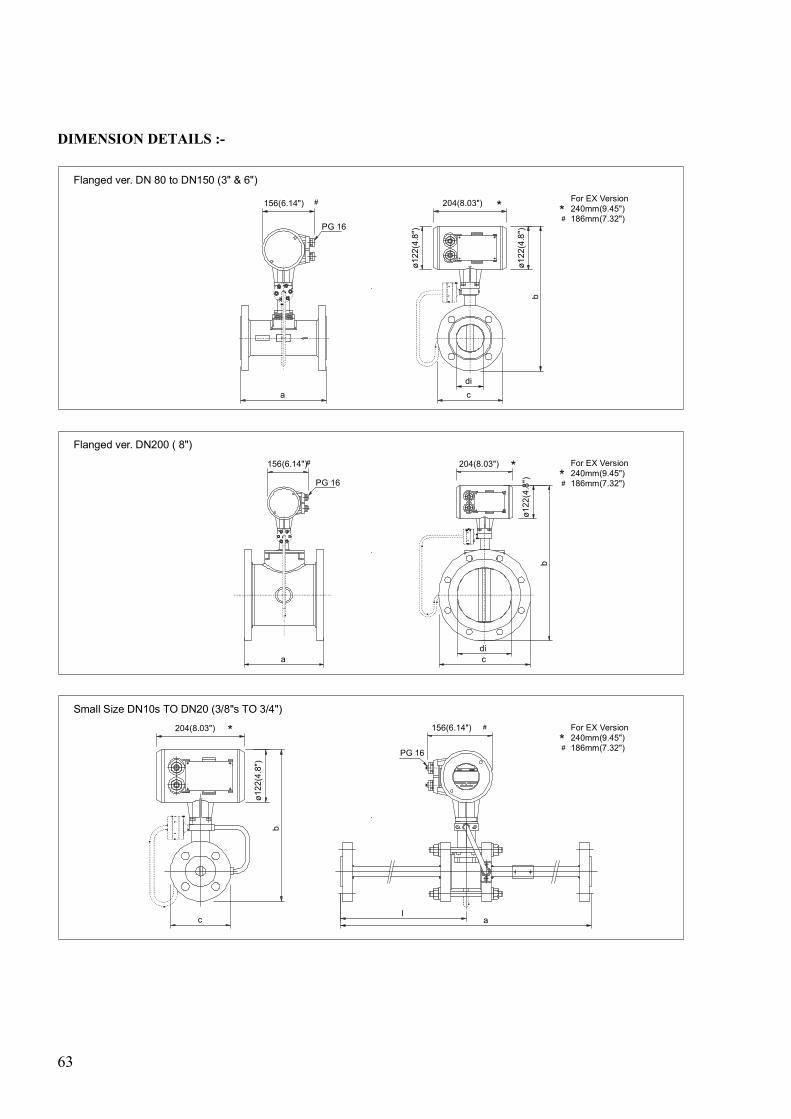
DIMENSION DETAILS :-
186mm(7.32")240mm(9.45")For EX Version
*#
Flanged ver. DN 80 to DN150 (3" & 6")
dic
204(8.03")156(6.14")
a
ø122
(4.8
")
b
# *PG 16
ø122
(4.8
")
adic
186mm(7.32")240mm(9.45")For EX Version
*#
Flanged ver. DN200 ( 8")
204(8.03")
ø122
(4.8
")
# *156(6.14")
PG 16
b
Small Size DN10s TO DN20 (3/8"s TO 3/4")204(8.03") 156(6.14")* #
la
ø122
(4.8
")
b
PG 16
For EX Version240mm(9.45")186mm(7.32")#
*
c
63
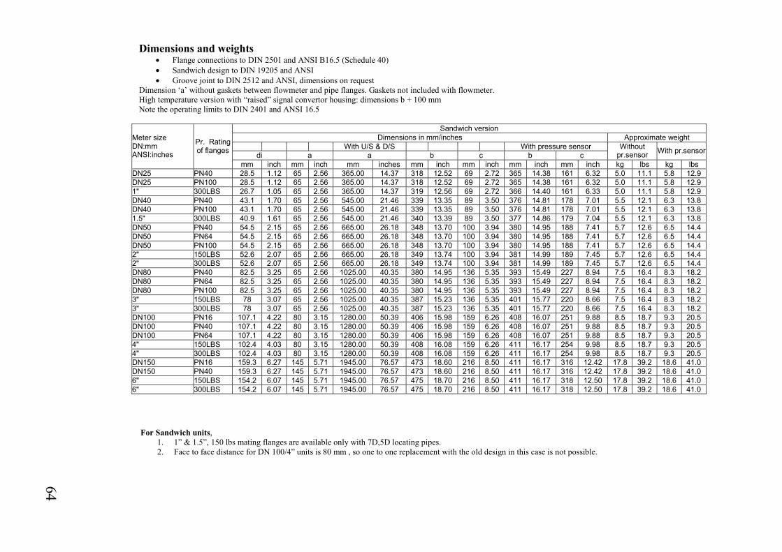
Sandwich version Dimensions in mm/inches Approximate weight
With U/S & D/S With pressure sensor di a a b c b c
Without pr.sensor With pr.sensor
Meter size DN:mm ANSI:inches
Pr. Rating of flanges
mm inch mm inch mm inches mm inch mm inch mm inch mm inch kg lbs kg lbsDN25 PN40 28.5 1.12 65 2.56 365.00 14.37 318 12.52 69 2.72 365 14.38 161 6.32 5.0 11.1 5.8 12.9DN25 PN100 28.5 1.12 65 2.56 365.00 14.37 318 12.52 69 2.72 365 14.38 161 6.32 5.0 11.1 5.8 12.91" 300LBS 26.7 1.05 65 2.56 365.00 14.37 319 12.56 69 2.72 366 14.40 161 6.33 5.0 11.1 5.8 12.9DN40 PN40 43.1 1.70 65 2.56 545.00 21.46 339 13.35 89 3.50 376 14.81 178 7.01 5.5 12.1 6.3 13.8DN40 PN100 43.1 1.70 65 2.56 545.00 21.46 339 13.35 89 3.50 376 14.81 178 7.01 5.5 12.1 6.3 13.81.5" 300LBS 40.9 1.61 65 2.56 545.00 21.46 340 13.39 89 3.50 377 14.86 179 7.04 5.5 12.1 6.3 13.8DN50 PN40 54.5 2.15 65 2.56 665.00 26.18 348 13.70 100 3.94 380 14.95 188 7.41 5.7 12.6 6.5 14.4DN50 PN64 54.5 2.15 65 2.56 665.00 26.18 348 13.70 100 3.94 380 14.95 188 7.41 5.7 12.6 6.5 14.4DN50 PN100 54.5 2.15 65 2.56 665.00 26.18 348 13.70 100 3.94 380 14.95 188 7.41 5.7 12.6 6.5 14.42" 150LBS 52.6 2.07 65 2.56 665.00 26.18 349 13.74 100 3.94 381 14.99 189 7.45 5.7 12.6 6.5 14.42" 300LBS 52.6 2.07 65 2.56 665.00 26.18 349 13.74 100 3.94 381 14.99 189 7.45 5.7 12.6 6.5 14.4DN80 PN40 82.5 3.25 65 2.56 1025.00 40.35 380 14.95 136 5.35 393 15.49 227 8.94 7.5 16.4 8.3 18.2DN80 PN64 82.5 3.25 65 2.56 1025.00 40.35 380 14.95 136 5.35 393 15.49 227 8.94 7.5 16.4 8.3 18.2DN80 PN100 82.5 3.25 65 2.56 1025.00 40.35 380 14.95 136 5.35 393 15.49 227 8.94 7.5 16.4 8.3 18.23" 150LBS 78 3.07 65 2.56 1025.00 40.35 387 15.23 136 5.35 401 15.77 220 8.66 7.5 16.4 8.3 18.23" 300LBS 78 3.07 65 2.56 1025.00 40.35 387 15.23 136 5.35 401 15.77 220 8.66 7.5 16.4 8.3 18.2DN100 PN16 107.1 4.22 80 3.15 1280.00 50.39 406 15.98 159 6.26 408 16.07 251 9.88 8.5 18.7 9.3 20.5DN100 PN40 107.1 4.22 80 3.15 1280.00 50.39 406 15.98 159 6.26 408 16.07 251 9.88 8.5 18.7 9.3 20.5DN100 PN64 107.1 4.22 80 3.15 1280.00 50.39 406 15.98 159 6.26 408 16.07 251 9.88 8.5 18.7 9.3 20.54" 150LBS 102.4 4.03 80 3.15 1280.00 50.39 408 16.08 159 6.26 411 16.17 254 9.98 8.5 18.7 9.3 20.54" 300LBS 102.4 4.03 80 3.15 1280.00 50.39 408 16.08 159 6.26 411 16.17 254 9.98 8.5 18.7 9.3 20.5DN150 PN16 159.3 6.27 145 5.71 1945.00 76.57 473 18.60 216 8.50 411 16.17 316 12.42 17.8 39.2 18.6 41.0DN150 PN40 159.3 6.27 145 5.71 1945.00 76.57 473 18.60 216 8.50 411 16.17 316 12.42 17.8 39.2 18.6 41.06" 150LBS 154.2 6.07 145 5.71 1945.00 76.57 475 18.70 216 8.50 411 16.17 318 12.50 17.8 39.2 18.6 41.06" 300LBS 154.2 6.07 145 5.71 1945.00 76.57 475 18.70 216 8.50 411 16.17 318 12.50 17.8 39.2 18.6 41.0
Dimensions and weights �� Flange connections to DIN 2501 and ANSI B16.5 (Schedule 40) �� Sandwich design to DIN 19205 and ANSI �� Groove joint to DIN 2512 and ANSI, dimensions on request
Dimension ‘a’ without gaskets between flowmeter and pipe flanges. Gaskets not included with flowmeter. High temperature version with “raised” signal convertor housing: dimensions b + 100 mm Note the operating limits to DIN 2401 and ANSI 16.5
For Sandwich units, 1. 1” & 1.5”, 150 lbs mating flanges are available only with 7D,5D locating pipes. 2. Face to face distance for DN 100/4” units is 80 mm , so one to one replacement with the old design in this case is not possible.
64
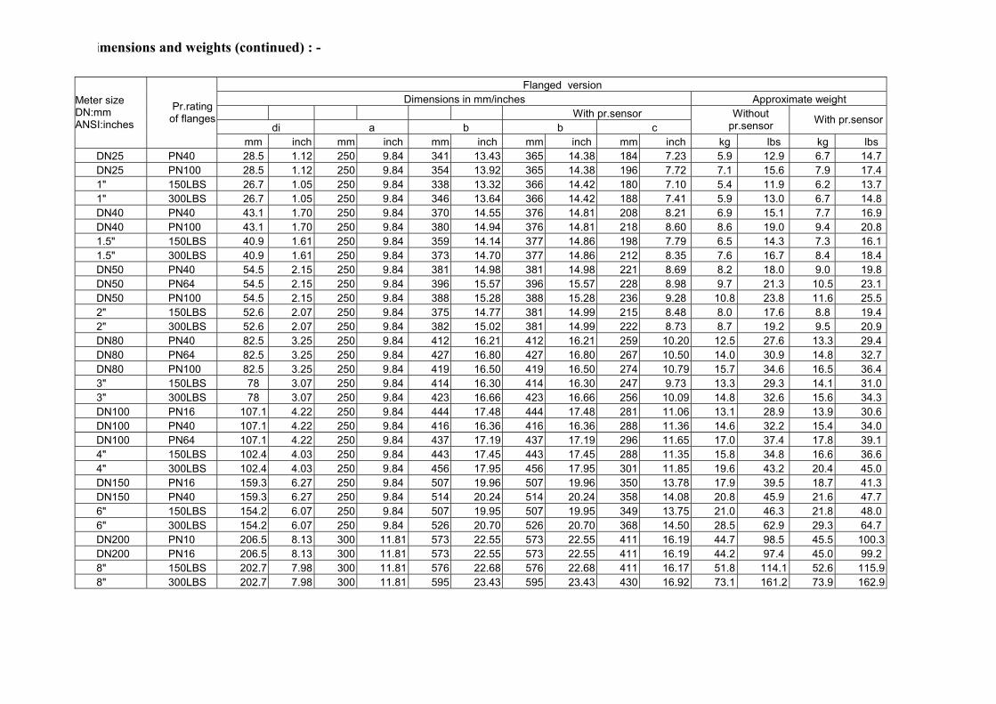
Flanged version Dimensions in mm/inches Approximate weight
With pr.sensordi a b b c
Without pr.sensor With pr.sensor
Meter size DN:mm ANSI:inches
Pr.rating of flanges
mm inch mm inch mm inch mm inch mm inch kg lbs kg lbsDN25 PN40 28.5 1.12 250 9.84 341 13.43 365 14.38 184 7.23 5.9 12.9 6.7 14.7DN25 PN100 28.5 1.12 250 9.84 354 13.92 365 14.38 196 7.72 7.1 15.6 7.9 17.41" 150LBS 26.7 1.05 250 9.84 338 13.32 366 14.42 180 7.10 5.4 11.9 6.2 13.71" 300LBS 26.7 1.05 250 9.84 346 13.64 366 14.42 188 7.41 5.9 13.0 6.7 14.8DN40 PN40 43.1 1.70 250 9.84 370 14.55 376 14.81 208 8.21 6.9 15.1 7.7 16.9DN40 PN100 43.1 1.70 250 9.84 380 14.94 376 14.81 218 8.60 8.6 19.0 9.4 20.81.5" 150LBS 40.9 1.61 250 9.84 359 14.14 377 14.86 198 7.79 6.5 14.3 7.3 16.11.5" 300LBS 40.9 1.61 250 9.84 373 14.70 377 14.86 212 8.35 7.6 16.7 8.4 18.4DN50 PN40 54.5 2.15 250 9.84 381 14.98 381 14.98 221 8.69 8.2 18.0 9.0 19.8DN50 PN64 54.5 2.15 250 9.84 396 15.57 396 15.57 228 8.98 9.7 21.3 10.5 23.1DN50 PN100 54.5 2.15 250 9.84 388 15.28 388 15.28 236 9.28 10.8 23.8 11.6 25.52" 150LBS 52.6 2.07 250 9.84 375 14.77 381 14.99 215 8.48 8.0 17.6 8.8 19.42" 300LBS 52.6 2.07 250 9.84 382 15.02 381 14.99 222 8.73 8.7 19.2 9.5 20.9DN80 PN40 82.5 3.25 250 9.84 412 16.21 412 16.21 259 10.20 12.5 27.6 13.3 29.4DN80 PN64 82.5 3.25 250 9.84 427 16.80 427 16.80 267 10.50 14.0 30.9 14.8 32.7DN80 PN100 82.5 3.25 250 9.84 419 16.50 419 16.50 274 10.79 15.7 34.6 16.5 36.43" 150LBS 78 3.07 250 9.84 414 16.30 414 16.30 247 9.73 13.3 29.3 14.1 31.03" 300LBS 78 3.07 250 9.84 423 16.66 423 16.66 256 10.09 14.8 32.6 15.6 34.3DN100 PN16 107.1 4.22 250 9.84 444 17.48 444 17.48 281 11.06 13.1 28.9 13.9 30.6DN100 PN40 107.1 4.22 250 9.84 416 16.36 416 16.36 288 11.36 14.6 32.2 15.4 34.0DN100 PN64 107.1 4.22 250 9.84 437 17.19 437 17.19 296 11.65 17.0 37.4 17.8 39.14" 150LBS 102.4 4.03 250 9.84 443 17.45 443 17.45 288 11.35 15.8 34.8 16.6 36.64" 300LBS 102.4 4.03 250 9.84 456 17.95 456 17.95 301 11.85 19.6 43.2 20.4 45.0DN150 PN16 159.3 6.27 250 9.84 507 19.96 507 19.96 350 13.78 17.9 39.5 18.7 41.3DN150 PN40 159.3 6.27 250 9.84 514 20.24 514 20.24 358 14.08 20.8 45.9 21.6 47.76" 150LBS 154.2 6.07 250 9.84 507 19.95 507 19.95 349 13.75 21.0 46.3 21.8 48.06" 300LBS 154.2 6.07 250 9.84 526 20.70 526 20.70 368 14.50 28.5 62.9 29.3 64.7DN200 PN10 206.5 8.13 300 11.81 573 22.55 573 22.55 411 16.19 44.7 98.5 45.5 100.3DN200 PN16 206.5 8.13 300 11.81 573 22.55 573 22.55 411 16.19 44.2 97.4 45.0 99.28" 150LBS 202.7 7.98 300 11.81 576 22.68 576 22.68 411 16.17 51.8 114.1 52.6 115.98" 300LBS 202.7 7.98 300 11.81 595 23.43 595 23.43 430 16.92 73.1 161.2 73.9 162.9
D
65 imensions and weights (continued) : -
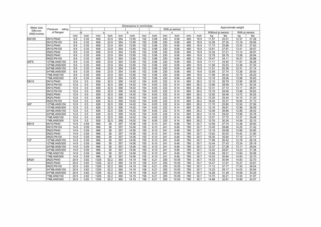
Dimensions in mm/inches With pr.sensor Approximate weight
di a b c c l Without pr.sensor With pr.sensor
Meter size DIN:mm
ANSI:inches
Pressure rating of flanges
mm inch mm inch mm inch mm inch mm inch mm inch kg lbs kg lbs DN10S DN10,PN40 8.9 0.35 606 23.9 354 13.95 152 5.98 230 9.06 480 18.9 11.57 25.51 12.37 27.28 DN10,PN100 8.9 0.35 606 23.9 354 13.95 152 5.98 230 9.06 480 18.9 12.38 27.30 13.18 29.06
DN15,PN40 8.9 0.35 606 23.9 354 13.95 152 5.98 230 9.06 480 18.9 11.73 25.86 12.53 27.63DN15,PN100 8.9 0.35 606 23.9 354 13.95 152 5.98 230 9.06 480 18.9 12.61 27.81 13.41 29.57DN20,PN40 8.9 0.35 606 23.9 354 13.95 152 5.98 230 9.06 480 18.9 12.34 27.21 13.14 28.97DN25,PN40 8.9 0.35 606 23.9 354 13.95 152 5.98 230 9.06 480 18.9 12.78 28.18 13.58 29.94DN25,PN100 8.9 0.35 606 23.9 354 13.95 152 5.98 230 9.06 480 18.9 15.47 34.11 16.27 35.88
3/8"S 1/2"NB,ANSI150 8.9 0.35 606 23.9 354 13.95 152 5.98 230 9.06 480 18.9 11.11 24.50 11.91 26.26 1/2"NB,ANSI300 8.9 0.35 606 23.9 354 13.95 152 5.98 230 9.06 480 18.9 11.58 25.53 12.38 27.30
3/4"NB,ANSI150 8.9 0.35 606 23.9 354 13.95 152 5.98 230 9.06 480 18.9 11.51 25.38 12.31 27.143/4"NB,ANSI300 8.9 0.35 606 23.9 354 13.95 152 5.98 230 9.06 480 18.9 12.58 27.74 13.38 29.501"NB,ANSI150 8.9 0.35 606 23.9 354 13.95 152 5.98 230 9.06 480 18.9 11.99 26.44 12.79 28.201"NB,ANSI300 8.9 0.35 606 23.9 354 13.95 152 5.98 230 9.06 480 18.9 13.18 29.06 13.98 30.83
DN10 DN10,PN40 12.6 0.5 826 32.5 356 14.02 154 6.05 232 9.14 665 26.2 12.15 26.79 12.95 28.55 DN10,PN100 12.6 0.5 826 32.5 356 14.02 154 6.05 232 9.14 665 26.2 12.96 28.58 13.76 30.34
DN15,PN40 12.6 0.5 826 32.5 356 14.02 154 6.05 232 9.14 665 26.2 12.31 27.14 13.11 28.91DN15,PN100 12.6 0.5 826 32.5 356 14.02 154 6.05 232 9.14 665 26.2 13.18 29.06 13.98 30.83DN20,PN40 12.6 0.5 826 32.5 356 14.02 154 6.05 232 9.14 665 26.2 12.92 28.49 13.72 30.25DN25,PN40 12.6 0.5 826 32.5 356 14.02 154 6.05 232 9.14 665 26.2 13.35 29.44 14.15 31.20DN25,PN100 12.6 0.5 826 32.5 356 14.02 154 6.05 232 9.14 665 26.2 16.04 35.37 16.84 37.13
3/8" 1/2"NB,ANSI150 12.6 0.5 826 32.5 356 14.02 154 6.05 232 9.14 665 26.2 11.70 25.80 12.50 27.56 1/2"NB,ANSI300 12.6 0.5 826 32.5 356 14.02 154 6.05 232 9.14 665 26.2 12.16 26.81 12.96 28.58
3/4"NB,ANSI150 12.6 0.5 826 32.5 356 14.02 154 6.05 232 9.14 665 26.2 12.09 26.66 12.89 28.423/4"NB,ANSI300 12.6 0.5 826 32.5 356 14.02 154 6.05 232 9.14 665 26.2 13.16 29.02 13.96 30.781"NB,ANSI150 12.6 0.5 826 32.5 356 14.02 154 6.05 232 9.14 665 26.2 12.57 27.72 13.37 29.481"NB,ANSI300 12.6 0.5 826 32.5 356 14.02 154 6.05 232 9.14 665 26.2 13.76 30.34 14.56 32.10
DN15 DN15,PN40 14.9 0.59 966 38 357 14.06 155 6.10 241 9.48 780 30.7 12.58 27.74 13.38 29.50 DN15,PN100 14.9 0.59 966 38 357 14.06 155 6.10 241 9.48 780 30.7 13.45 29.66 14.25 31.42
DN20,PN40 14.9 0.59 966 38 357 14.06 155 6.10 241 9.48 780 30.7 13.19 29.08 13.99 30.85DN25,PN40 14.9 0.59 966 38 357 14.06 155 6.10 241 9.48 780 30.7 13.62 30.03 14.42 31.80DN25,PN100 14.9 0.59 966 38 357 14.06 155 6.10 241 9.48 780 30.7 16.30 35.94 17.10 37.71
1/2" 1/2"NB,ANSI150 14.9 0.59 966 38 357 14.06 155 6.10 241 9.48 780 30.7 11.98 26.42 12.78 28.18 1/2"NB,ANSI300 14.9 0.59 966 38 357 14.06 155 6.10 241 9.48 780 30.7 12.44 27.43 13.24 29.19
3/4"NB,ANSI150 14.9 0.59 966 38 357 14.06 155 6.10 241 9.48 780 30.7 12.37 27.28 13.17 29.043/4"NB,ANSI300 14.9 0.59 966 38 357 14.06 155 6.10 241 9.48 780 30.7 13.43 29.61 14.23 31.381"NB,ANSI150 14.9 0.59 966 38 357 14.06 155 6.10 241 9.48 780 30.7 12.84 28.31 13.64 30.081"NB,ANSI300 14.9 0.59 966 38 357 14.06 155 6.10 241 9.48 780 30.7 14.03 30.94 14.83 32.70
DN20 DN20,PN40 20.9 0.82 1326 52.2 360 14.19 158 6.21 255 10.05 780 30.7 14.03 30.94 14.83 32.70 DN25,PN40 20.9 0.82 1326 52.2 360 14.19 158 6.21 255 10.05 780 30.7 14.47 31.91 15.27 33.67
DN25,PN100 20.9 0.82 1326 52.2 360 14.19 158 6.21 255 10.05 780 30.7 17.13 37.77 17.93 39.543/4" 3/4"NB,ANSI150 20.9 0.82 1326 52.2 360 14.19 158 6.21 255 10.05 780 30.7 13.23 29.17 14.03 30.94 3/4"NB,ANSI300 20.9 0.82 1326 52.2 360 14.19 158 6.21 255 10.05 780 30.7 14.28 31.49 15.08 33.25
1"NB,ANSI150 20.9 0.82 1326 52.2 360 14.19 158 6.21 255 10.05 780 30.7 13.70 30.21 14.50 31.971"NB,ANSI300 20.9 0.82 1326 52.2 360 14.19 158 6.21 255 10.05 780 30.7 14.88 32.81 15.68 34.57
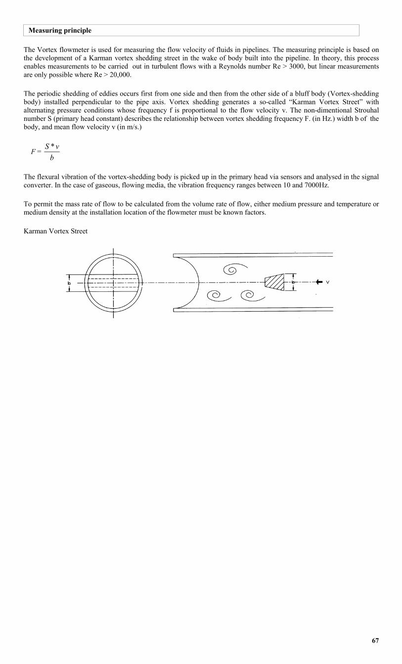
Measuring principle
The Vortex flowmeter is used for measuring the flow velocity of fluids in pipelines. The measuring principle is based on the development of a Karman vortex shedding street in the wake of body built into the pipeline. In theory, this process enables measurements to be carried out in turbulent flows with a Reynolds number Re > 3000, but linear measurements are only possible where Re > 20,000.
The periodic shedding of eddies occurs first from one side and then from the other side of a bluff body (Vortex-shedding body) installed perpendicular to the pipe axis. Vortex shedding generates a so-called “Karman Vortex Street” with alternating pressure conditions whose frequency f is proportional to the flow velocity v. The non-dimentional Strouhal number S (primary head constant) describes the relationship between vortex shedding frequency F. (in Hz.) width b of the body, and mean flow velocity v (in m/s.)
F = b
vS *
The flexural vibration of the vortex-shedding body is picked up in the primary head via sensors and analysed in the signal converter. In the case of gaseous, flowing media, the vibration frequency ranges between 10 and 7000Hz.
To permit the mass rate of flow to be calculated from the volume rate of flow, either medium pressure and temperature or medium density at the installation location of the flowmeter must be known factors.
Karman Vortex Street
67
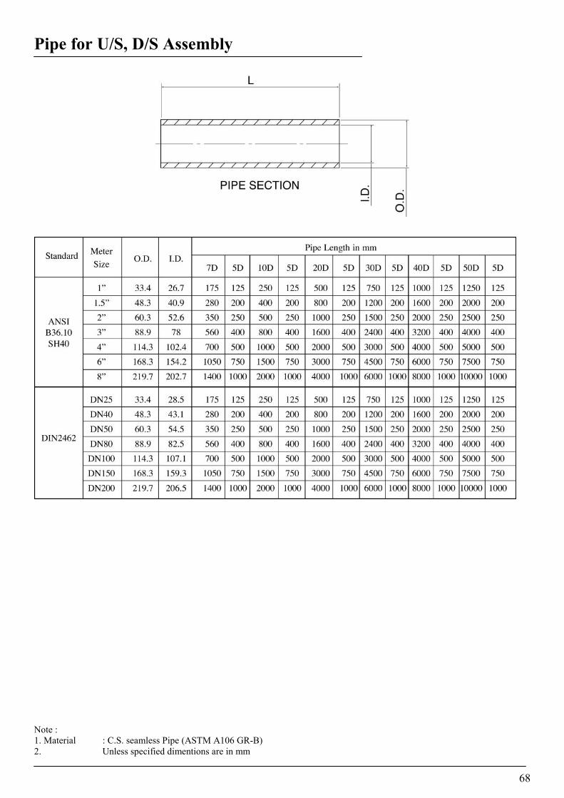
Pipe for U/S, D/S Assembly
Note : 1. Material : C.S. seamless Pipe (ASTM A106 GR-B) 2. Unless specified dimentions are in mm
68
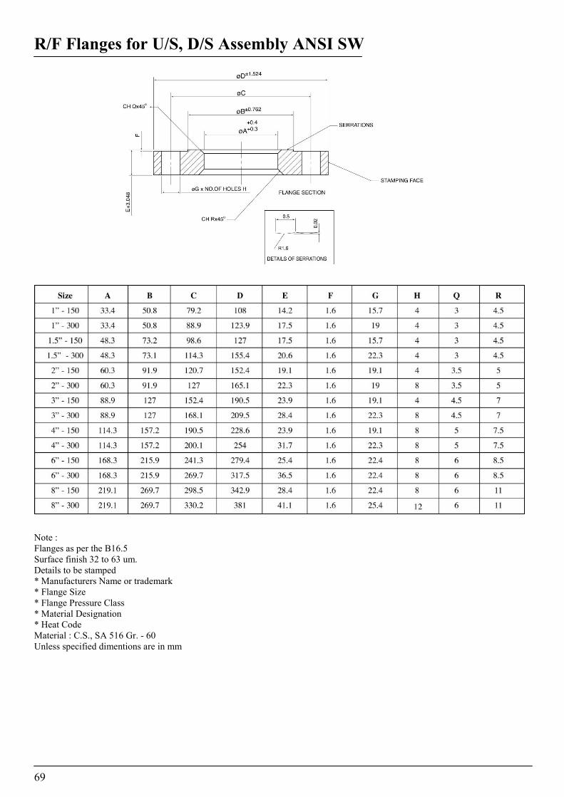
R/F Flanges for U/S, D/S Assembly ANSI SW
Note : Flanges as per the B16.5 Surface finish 32 to 63 um. Details to be stamped * Manufacturers Name or trademark * Flange Size * Flange Pressure Class * Material Designation * Heat Code Material : C.S., SA 516 Gr. - 60 Unless specified dimentions are in mm Note : Flanges as per the B16.5 Surface finish 32 to 63 um. Details to be stamped * Manufacturers Name or trademark * Flange Size * Flange Pressure Class * Material Designation * Heat Code Material : C.S., SA 516 Gr. - 60 Unless specified dimentions are in mm
69
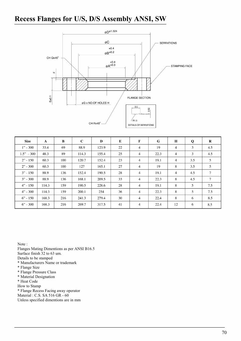
Recess Flanges for U/S, D/S Assembly ANSI, SW
Note : Flanges Mating DSurface finish 32Details to be stam* Manufacturers * Flange Size * Flange Pressur* Material Desig* Heat Code How to Stamp * Flange Recess Material : C.S. SUnless specified
imentions as per ANSI B16.5 to 63 um. ped
Name or trademark
e Class nation
Facing away operator A 516 GR - 60 dimentions are in mm
70
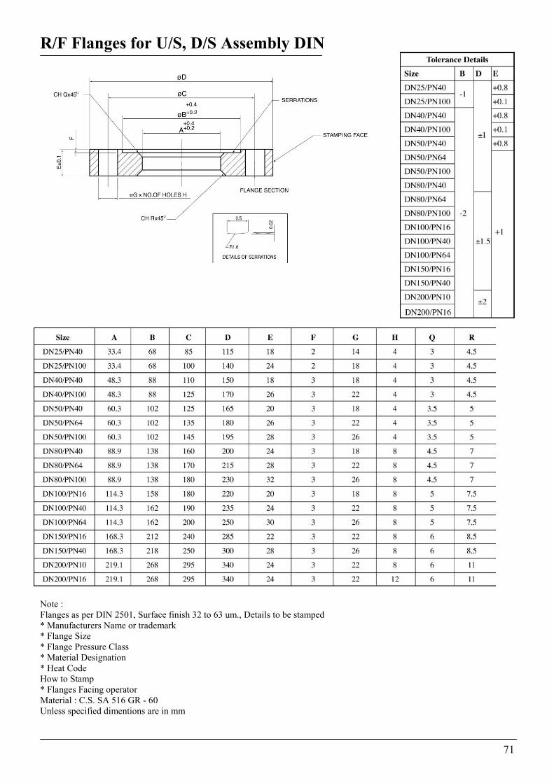
R/F Flanges for U/S, D/S Assembly DIN
Note : Flanges as per DIN 2501, Surface finish 32 to 63 um., Details to be stamped * Manufacturers Name or trademark * Flange Size * Flange Pressure Class * Material Designation * Heat Code How to Stamp * Flanges Facing operator Material : C.S. SA 516 GR - 60 Unless specified dimentions are in mm
71
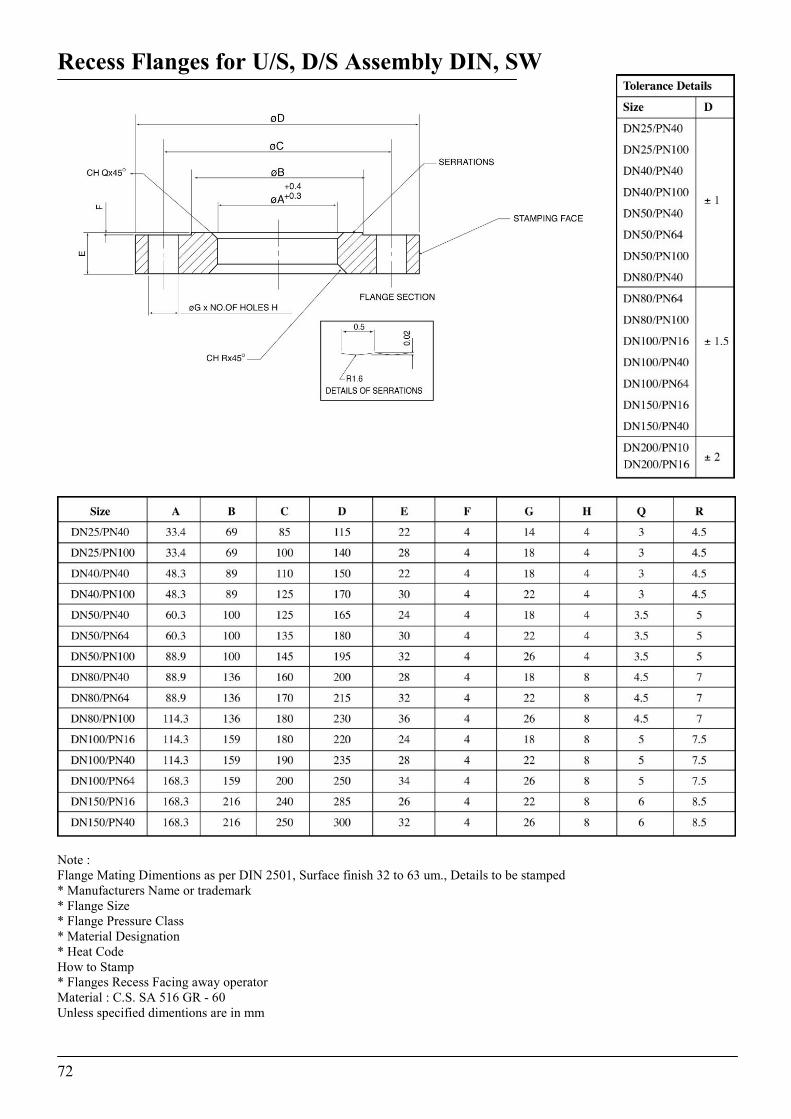
Recess Flanges for U/S, D/S Assembly DIN, SW
Note : Flange Mating Dimentions as per DIN 2501, Surface finish 32 to 63 um., Details to be stamped * Manufacturers Name or trademark * Flange Size * Flange Pressure Class * Material Designation * Heat Code How to Stamp * Flanges Recess Facing away operator Material : C.S. SA 516 GR - 60 Unless specified dimentions are in mm
72

Up Stream & Down Stream Assembly for SW
Note : * One set of U/S Assly. and one set of D/S Assly is to be supplied * To be painted with heat resistant paint. * Flanges to welded off center. * Welding std.- Ad-Merkblatt B8 Material : C.S. Unless specified dimentions are in mm
73
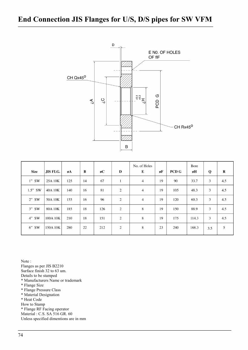
End Connection JIS Flanges for U/S, D/S pipes for SW VFM
Note : Flanges as per JIS B2210 Surface finish 32 to 63 um. Details to be stamped * Manufacturers Name or trademark * Flange Size * Flange Pressure Class * Material Designation * Heat Code How to Stamp * Flange RF Facing operator Material : C.S. SA 516 GR. 60 Unless specified dimentions are in mm
74
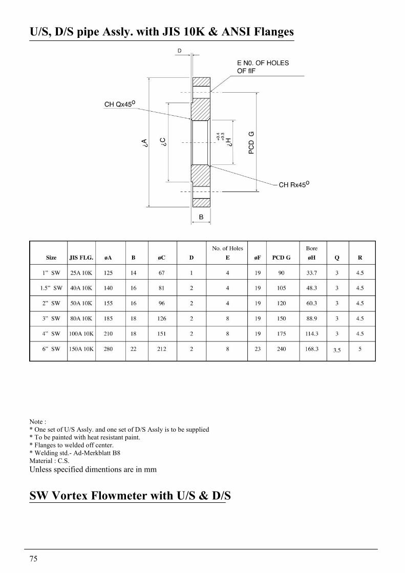
U/S, D/S pipe Assly. with JIS 10K & ANSI Flanges
Note : * One set of U/S Assly. and one set of D/S Assly is to be supplied * To be painted with heat resistant paint. * Flanges to welded off center. * Welding std.- Ad-Merkblatt B8 Material : C.S. Unless specified dimentions are in mm SW Vortex Flowmeter with U/S & D/S
75
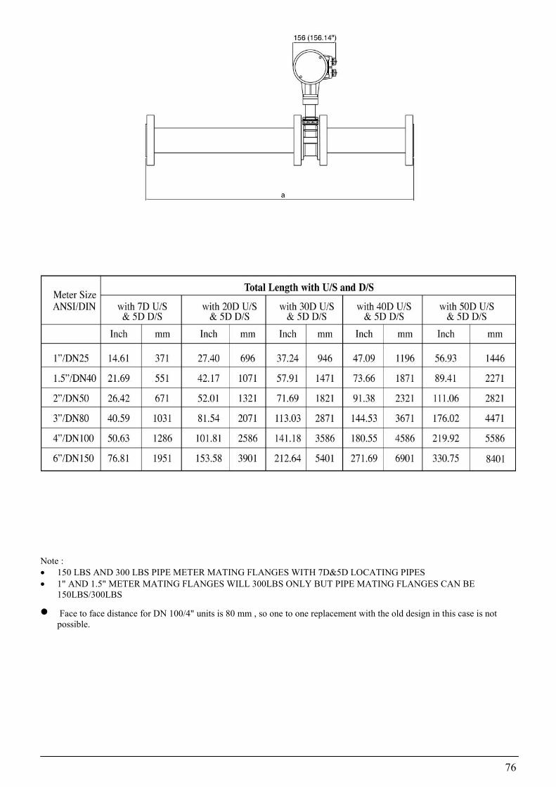
Note : �� 150 LBS AND 300 LBS PIPE METER MATING FLANGES WITH 7D&5D LOCATING PIPES �� 1" AND 1.5" METER MATING FLANGES WILL 300LBS ONLY BUT PIPE MATING FLANGES CAN BE
150LBS/300LBS
�� Face to face distance for DN 100/4" units is 80 mm , so one to one replacement with the old design in this case is not possible.
76

Krohne Marshall Ltd. A -34 / 35 MIDC, 'H' Blk, Pimpri, Pune 411 018 Tel : 91 (0) 20-7470171 Fax : 91 (0) 20-7477049 After Office Hrs: 020-7477762
Subject to change without notice