42gr atm air treatment module · 2010-03-30 · carrier linear diffusers in the false ceiling....
TRANSCRIPT

42GR ATMAir Treatment ModuleNominal air flow, size 1: 97 l/s - 350 m3/h
size 2: 139 l/s - 500 m3/h
Installation manual

The photos shown on the front cover are solely forinformation, and not contractually binding. Themanufacturer reserves the right to make changes withoutprevious notification.
Contents
1 - INTRODUCTION..............................................................4
2 - FEATURES.........................................................................62.1 - Physical and electrical data...............................................62.2 - Suspension casing drawings .............................................72.3 - Dimensional drawings - ATM...........................................92.4 - Dimensional drawings - casings .....................................112.5 - Condensate drain dimensions .........................................122.6 - Suspension casings - packaging......................................132.7 - Suspension rails ..............................................................13
3 - SAFETY CONSIDERATIONS.......................................143.1 - General ............................................................................143.2 - Precautions against electrocution....................................143.3 - Installation Recommendations........................................143.4 - Conformity......................................................................14
4 - SUSPENSION CASING..................................................15
5 - AIR TREATMENT MODULE.......................................165.1 - Installation.......................................................................165.2 - Removal ..........................................................................16
6 - FRESH AIR ......................................................................176.1 - Standard suspension casing ............................................176.2 - All fresh air suspension casing .......................................176.3 - Constant fresh air volume suspension casing.................176.4 - Variable fresh air volume suspension casing..................176.5 - Air Treatment Module ATM ...........................................18
7 - FAN MOTOR ASSEMBLY.............................................197.1 - Description......................................................................197.2 - Fan motor removal..........................................................19
8 - WATER COIL..................................................................208.1 - Removing the coil...........................................................208.2 - Water inlet/outlet connections.........................................21
9 - WATER FLOW CONTROL VALVES...........................229.1 - Electrothermal actuator (on/off) .....................................229.2 - Replacing actuators.........................................................229.3 - Electrical cicuit diagrams for actuators ..........................229.4 - Replacing a valve body...................................................23
10 - FLEXIBLE WATER PIPES..........................................23
11 - FILTER ...........................................................................24
12 - ELECTRIC HEATER...................................................2412.1 - Removing the electric heater from the size 1 ATM......2512.2 - Removing the electric heater from the size 2 ATM......25
13 - PERFORMANCES........................................................2613.1 - Electrical data ...............................................................2613.2 - Air flow/available static pressure data..........................27
14 - CONTROLLER .............................................................2914.1 - Carrier numeric controller ............................................2914.2 - Carrier electromechanical controller
with fan speed controller ..............................................2914.3 - The various ATM configurations available ..................3014.4 - Technical specifications for the
heating/cooling changeover switch...............................3014.5 - Master/slave control......................................................3114.6 - Wiring diagrams............................................................33

44
1 - INTRODUCTION
The 42GR Air Treatment Module (ATM) is something morethan a simple air conditioner which enables room airtemperature to be controlled. It is a total, integrated comfortsystem in the building.
The Carrier 42GR is a compact central station air handler intwo sizes able to supply conditioned air at rates from 97 l/s to139 l/s to rooms with floor areas from 25 to 40 m2. The maincomponents of the unit are a centrifugal fan, an air filter, a hotwater heating coil or an electric resistance heater and a chilledwater cooling coil. The unit is controlled by a Carrier numericcontroller or similar.
The 42GR is connected, on site, through two flexible ducts(low thermal conductivity, low noise transmission supplied byothers) to one or more high induction plenums fitted withCarrier linear diffusers in the false ceiling. Typically, these willbe Carrier Moduboot 35BD/35SR units with each one servingan individual room or zone and providing both supply air andreturn air paths according to diffuser model.
The top of the range 42GR ATM can have a Carrier numericcontroller. Each room occupant then has his or her own Zone
User Interface control module, on a wall (with a mountingbase) or desk, with which to select the preferred comfort level:� Room ambient temperature� Select Occupied or Unoccupied mode at each 42GR ATM to
control energy usage� Ventilation air (the rate of air replacement) � Lighting on or off� Blinds raised or lowered and their inclination
In addition, connection to a central Building ManagementSystem allows units to be controlled individually to satisfyoverriding criteria or to respond to local regulations.
The 42GR ATM is designed to be installed in a machine roomclose to the centre of the space to be air conditioned. Modulescan be installed side by side and their high static pressurecapability allow them to be used with long ducts.
With the 42GR ATM located centrally in one machine room,service and maintenance are considerably easier.
WARNING:Switch off the electrical power supply before doing any workon the unit.
CHILLED/HOT WATERSUPPLY AND RETURN
MODUBOOT RETURNAIR UNIT

5
ATM: 3 main components
SUSPENSION RAIL
SUSPENSION CASING
AIR TREATMENT MODULE (ATM)

6
42GR ATM Size 1 Size 2
Nominal air flow l/s (m3/h) 97 (350) 139 (500)
Total cooling capacity(1) (at nominal air flow) kW 2.8 4.1
Sensible cooling capacity(1) (at nominal air flow) kW 1.9 2.7
Heating capacity(2) (at nominal air flow) kW 1.2 2.2
Power supply 230 V-1 ph- 50 Hz U% ± 15 ± 15
Operating weight (6-row coil) kg 35 50
Water coil 3/8” copper tubes, aluminium finsat 1.8 mm spacing, test pressure 24 bar,operating pressure 16 bar• 6-row coil: 5 cooling rows, 1 heating row• 5-row cooling coil• Cooling water volume l 0.83 1.5• Heating water volume l 0.17 0.3
PTC electric heater (Positive Temperature Coefficient)• Max. capacity at nominal air flow kW 1.7 1.8• Current draw ± 15% A 11 11• Power input at zero flow W 80 80• VDE, CE, UL and CSA codes approved
Fan• Centrifugal fan, single wheel single inlet double inlet- Nominal air flow l/s (m3/h) 97 (350) 139 (500)- Static pressure at nominal air flow Pa 310 320
Fan motor230 V-1 ph-50 Hz, 2-pole open asynchronous, permanent capacitor, inherent overloadprotection, class B insulation, varnishclass F, connected to a speed controller.• Protection index IP 44 44• Max. power input at 230 VAC(4) W 143 208• Min. output from electronic speed controller (RMS) V 80 80• Nominal current(4) A 0.64 0.91• Starting current A 2.56 3.64
Air filterThrowaway, 55 mm thick, type F5,fire rating medium M1, metal frame• Dimensions mm 225x350 395x350• Pressure drop, clean
air flow 97 l/s Pa 35 –air flow 139 l/s Pa – 35
Fresh air connection on ATM(3)
• External diameter mm 75 125• Constant air flow (-10%, + 20%) l/s (m3/h) 8.3 (30) 16.6 (60)• ∆P (upstream/downstream) Pa 50/200 70/200
Water connections42GR modules are designed and tested for 16 bar operating pressure. The total operating circuit of the ATM is guaranteed for anoperating pressure of 10 bar.Contact your local Carrier representative for advice when an application calls for an operating pressure of 16 bar.
2 - FEATURES
2.1 - Physical and electrical data
Notes:(1) Based upon water entering at 6°C, room air at 25°C dry bulb, 50%
relative humidity, 5 K ∆t and nominal air flow.(2) Based upon water entering at 50°C, room air at 19°C, 10 K ∆t and
nominal air flow.(3) In the case of the size 2 ATM, the fresh air controller may be
modified on site by relocating or removing two plastic restricters inorder to increase its constant fresh air flow capacity to 20.8 (75),27.7 (100), 36.1 (130), 44.4 l/s (160 m3/h)
(4) Refer to extended electrical data table

7
Size 1
Size 1
Size 2
Size 2
2.2 - Suspension casing drawings
Standard suspension casing, mm
All fresh air suspension casing, mm
SUPPLY SUSPENSIONCASING
SUPPLY SUSPENSIONCASING
RETURN
RETURN
SUPPLY SUSPENSIONCASING
FRESH AIR
SUPPLYSUSPENSION
CASING
FRESHAIR
Plastic cap to cover thereturn air inlet
Plastic cap to cover thereturn air inlet

8
Size 1
Size 1
Size 2
Size 2
Constant fresh air volume suspension casing, mm
Variable fresh air volume suspension casing, mm
RETURN
SUPPLYSUSPENSION
CASING
FRESHAIR
RETURN
SUPPLYSUSPENSION
CASING
FRESHAIR
RETURN
SUPPLY SUSPENSIONCASING
FRESH
RETURN
SUPPLY SUSPENSION
FRESH

9
2.3 - Dimensional drawings
2.3.1 - ATM with no fresh air inlet
42GR size 1, mm
CONDENSATE DRAIN16 mm DIA.
42GR size 2, mm
CONDENSATE DRAIN16 mm DIA.

10
2.3.2 - ATM with fresh air inlet
42GR size 1, mm
FRESH AIRINLET
CONDENSATE DRAIN16 mm DIA.
42GR size 2, mm
FRESHAIR
INLET
CONDENSATE DRAIN16 mm DIA.
MAX. 450
MAX. 450

11
CONTROLLER
RETURN
SUSPENSIONCASING
SUPPLY
ATM
CONTROLLER
RETURN
SUSPENSIONCASING
SUPPLY
ATM
2.4 - Dimensional drawings
ATM with all fresh air or constant fresh air volume suspension casing, mm
ATM with standard suspension casing, mm
FRESHAIR
INLET
FRESH AIRINLET
12
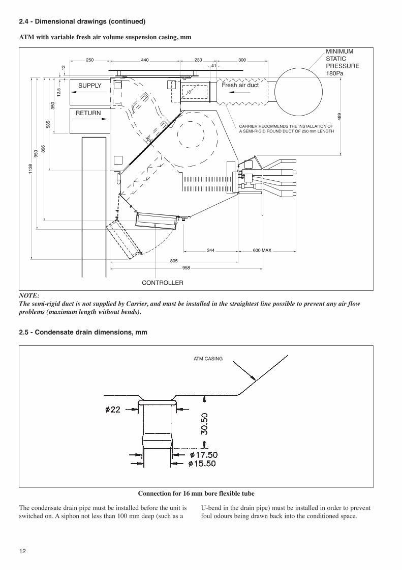
2.4 - Dimensional drawings (continued)
ATM with variable fresh air volume suspension casing, mm
NOTE:The semi-rigid duct is not supplied by Carrier, and must be installed in the straightest line possible to prevent any air flowproblems (maximum length without bends).
2.5 - Condensate drain dimensions, mm
ATM CASING
Connection for 16 mm bore flexible tube
The condensate drain pipe must be installed before the unit isswitched on. A siphon not less than 100 mm deep (such as a
U-bend in the drain pipe) must be installed in order to preventfoul odours being drawn back into the conditioned space.
CONTROLLER
MINIMUM STATIC PRESSURE180Pa
CARRIER RECOMMENDS THE INSTALLATION OFA SEMI-RIGID ROUND DUCT OF 250 mm LENGTH
RETURN
SUPPLY Fresh air duct
13
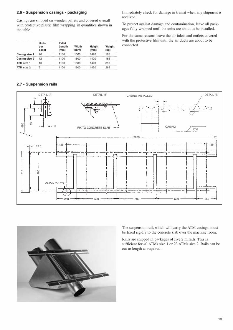
2.6 - Suspension casings - packaging
Casings are shipped on wooden pallets and covered overallwith protective plastic film wrapping, in quantities shown inthe table.
Units Palletper Length Width Height Weightpallet (mm) (mm) (mm) (kg)
Casing size 1 20 1100 1600 1420 185
Casing size 2 12 1100 1600 1420 165
ATM size 1 10 1100 1600 1420 310
ATM size 2 5 1100 1600 1420 265
Immediately check for damage in transit when any shipment isreceived.
To protect against damage and contamination, leave all pack-ages fully wrapped until the units are about to be installed.
For the same reasons leave the air inlets and outlets coveredwith the protective film until the air ducts are about to beconnected.
DETAIL "A"
DETAIL "A"
12.5
518
480
125 125
250 500 500 500 250
2000
11 FIX TO CONCRETE SLAB
CASING INSTALLED
CASINGATM
919
480
DETAIL "B" DETAIL "B"
2.7 - Suspension rails
The suspension rail, which will carry the ATM casings, mustbe fixed rigidly to the concrete slab over the machine room.
Rails are shipped in packages of five 2 m rails. This issufficient for 40 ATMs size 1 or 23 ATMs size 2. Rails can becut to length as required.
14
3 - SAFETY CONSIDERATIONS
3.1 - General
Installing, commissioning and servicing of the variouscomponents which make up the different control loops can bedangerous unless certain aspects of the installation, such as thepresence of mains electricity and hot or chilled-water in the airconditioning equipment, are taken into account.
Only specially trained and qualified technicians and installerswho have been fully trained on the product concerned areauthorised to install, commission and service this equipment.
During servicing work, it is essential to apply allrecommendations and instructions given in service leaflets, onlabels or in the instructions delivered with the equipment, andto comply with any other relevant instructions.
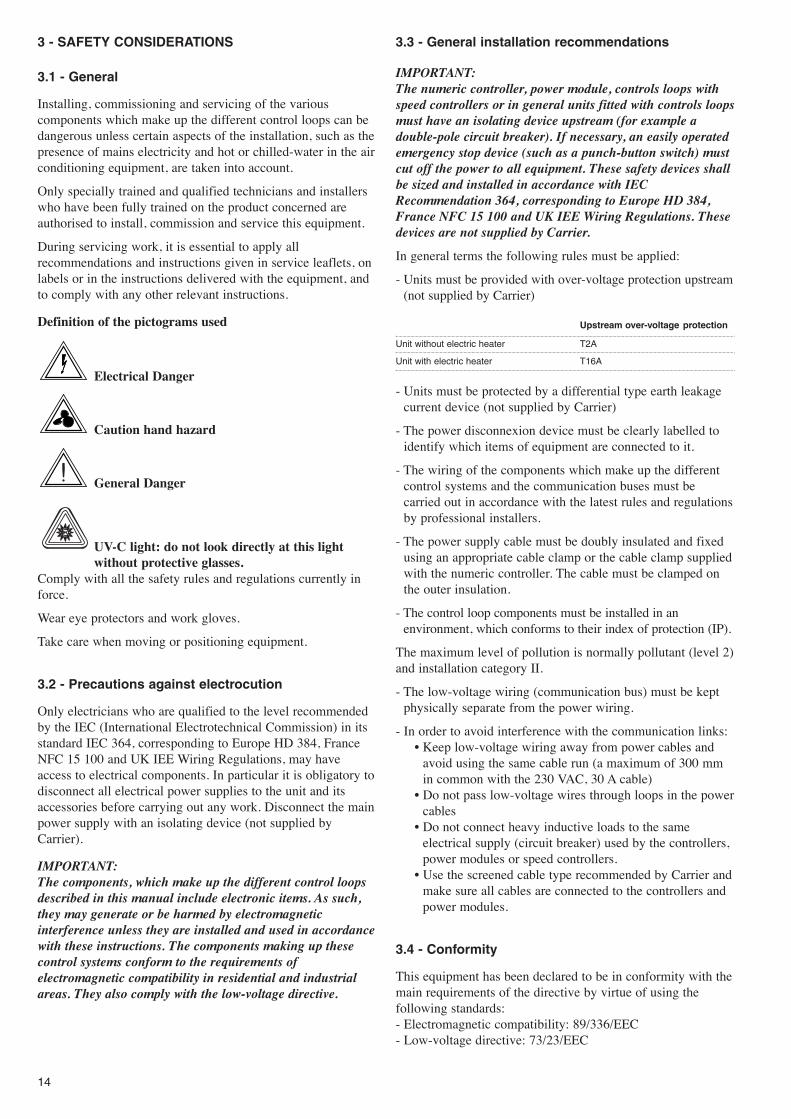
Definition of the pictograms used
Electrical Danger
Caution hand hazard
General Danger
UV-C light: do not look directly at this light without protective glasses.
Comply with all the safety rules and regulations currently inforce.
Wear eye protectors and work gloves.
Take care when moving or positioning equipment.
3.2 - Precautions against electrocution
Only electricians who are qualified to the level recommendedby the IEC (International Electrotechnical Commission) in itsstandard IEC 364, corresponding to Europe HD 384, FranceNFC 15 100 and UK IEE Wiring Regulations, may haveaccess to electrical components. In particular it is obligatory todisconnect all electrical power supplies to the unit and itsaccessories before carrying out any work. Disconnect the mainpower supply with an isolating device (not supplied byCarrier).
IMPORTANT:The components, which make up the different control loopsdescribed in this manual include electronic items. As such,they may generate or be harmed by electromagneticinterference unless they are installed and used in accordancewith these instructions. The components making up thesecontrol systems conform to the requirements ofelectromagnetic compatibility in residential and industrialareas. They also comply with the low-voltage directive.
3.3 - General installation recommendations
IMPORTANT:The numeric controller, power module, controls loops withspeed controllers or in general units fitted with controls loopsmust have an isolating device upstream (for example adouble-pole circuit breaker). If necessary, an easily operatedemergency stop device (such as a punch-button switch) mustcut off the power to all equipment. These safety devices shallbe sized and installed in accordance with IECRecommendation 364, corresponding to Europe HD 384,France NFC 15 100 and UK IEE Wiring Regulations. Thesedevices are not supplied by Carrier.
In general terms the following rules must be applied:
- Units must be provided with over-voltage protection upstream(not supplied by Carrier)
Upstream over-voltage protection
Unit without electric heater T2A
Unit with electric heater T16A
- Units must be protected by a differential type earth leakagecurrent device (not supplied by Carrier)
- The power disconnexion device must be clearly labelled toidentify which items of equipment are connected to it.
- The wiring of the components which make up the differentcontrol systems and the communication buses must becarried out in accordance with the latest rules and regulationsby professional installers.
- The power supply cable must be doubly insulated and fixedusing an appropriate cable clamp or the cable clamp suppliedwith the numeric controller. The cable must be clamped onthe outer insulation.
- The control loop components must be installed in anenvironment, which conforms to their index of protection (IP).
The maximum level of pollution is normally pollutant (level 2)and installation category II.
- The low-voltage wiring (communication bus) must be keptphysically separate from the power wiring.
- In order to avoid interference with the communication links:� Keep low-voltage wiring away from power cables and
avoid using the same cable run (a maximum of 300 mmin common with the 230 VAC, 30 A cable)
� Do not pass low-voltage wires through loops in the powercables
� Do not connect heavy inductive loads to the sameelectrical supply (circuit breaker) used by the controllers,power modules or speed controllers.
� Use the screened cable type recommended by Carrier andmake sure all cables are connected to the controllers andpower modules.
3.4 - Conformity
This equipment has been declared to be in conformity with themain requirements of the directive by virtue of using thefollowing standards:- Electromagnetic compatibility: 89/336/EEC- Low-voltage directive: 73/23/EEC

15
4 - SUSPENSION CASING
This carries the ATM itself and provides the means fortraversing the machine room partition. It comprises a non-insulated plenum within which an insulated duct carries thesupply air.
The modular design allows these units to be installed whilebuilding proceeds so that air ducts and the false ceiling can beinstalled much sooner than is usual. The operative section ofthe ATM need not be installed until just before the tenantsarrive. They can be ordered for delivery very late in thebuilding cycle - a very important financial consideration wheremajor installations are involved.
There are 4 types of suspension casing. The selectionparameters are explained:
WARNING:Once installed with ducts connected and the false ceiling
completed, it is almost impossible to remove these units.
With the exception of the removable constant air flowcontrollers and the electronic fresh air flow control module,there are no wearing parts in these casings.
Ducts connect the casings to the diffusers. The pressure dropsthrough the ducts must be compatible with the performance ofthe ATMs. The internal duct surfaces must be as smooth aspossible. Avoid sharp bends. Check that there are no leaks andthat they have not become fouled during installation.
Protect the ducts against the ingress of building debris whichcould be sucked into the unit possibly damaging the fan andthe thermostatic damper on the diffuser.
As required by local sound emission codes install soundabsorbing and damping materials.

16
CONCRETE CEILING
SEE DETAILS IN CHAPTER 2.7 “SUSPENSION RAILS”
SUSPENSION CASING
FILTER ACCESSDOOR OPENED
SUSPENSION CASING
CONTROLLER
FALSE CEILING
SUSPENSIONHOOK
MACHINE ROOMWALL
ATM
GASKET
LATCH
SUPPLY
RETURN
5 - AIR TREATMENT MODULE
5.1 - Installation
The Air Treatment Module (ATM) is generally the lastcomponent to be installed when all else is done. There are threereasons for this:
- Avoidance of damage to the units while heavy work is still inprogress
- Releasing capital
- Keeping work areas as free of clutter as possible.
When the site is ready for the modules - casings are hookedonto the rails, air ducts are connected, water manifolds andshut-off valves are in place on their connection spigots,electrical installation is complete - only a few minutes are
needed to install the module, make the hydraulic and electricalconnections and connect the condensate drain. Adequate filteraccess and manoeuvring space will have been provided (referto the dimensional drawings).
WARNING:Do not use the water valves or pipes or the electrical cables ashandles for manoeuvring the modules. They may sufferserious damage.
To fix the ATM on its casing, first hook it onto the suspensionhooks provided then push it against the casing. This has theeffect of compressing the gasket and locking the suspensionlatch. Next connect the water pipes. When all modules areinstalled in this way open the shut-off valves on the manifolds,bleed all air from the circuits (bleed valves are on the coilwater outlets) then pressurise the system.
Now the electrical connections can be made. Do not switch thepower on until the electrical installation is complete.
5.2 - Removal
- Disconnect the power supply by switching off the circuitbreaker which must have been installed at the outset.
- Disconnect the supply cables.- Close the water shut-off valves.- Disconnect the water pipes.- Disconnect the fresh air supply if fitted.- Unlatch the suspension latch.- Gently lower the unit to disengage it from the upper section.
Pull it back about 10 mm to disengage it, then remove it.
SIDE ASIZE 1: 334 mm min.SIZE 2: 416 mm min.
ATM assembled on its suspension casing

17
6 - FRESH AIR
6.1 - Standard suspension casing
The ATM can have a fresh air controller to give precise controlof the volume of fresh ventilation air admitted to the conditionedspace. Space occupancy determines the fresh air requirement andthe choice of controller. The size 1 ATM has a 8.3 l/s (30 m3/h)fresh air controller. A 450 mm length of 80 mm diameter flexibleduct (Class M1 fire rated) is supplied with every size 1 ATM.
The size 2 ATM has a 16.6 l/s (60 m3/h) fresh air controller,and a 450 mm length of 125 mm diameter flexible duct (ClassM1 fire rated) is supplied with every size 2 ATM.
NOTE:Every duct has a metal collar to connect it to the main freshair supply duct.
Fresh air controllers need no special maintenance, but can beeasily removed. Fresh air must be filtered upstream of the ATM.
Fresh air ducts must be completely clear of debris before theunit is started up.
6.2 - All fresh air suspension casing
This is for use on an ATM which is intended to operate usingfresh air only, such as in a conference room.
The casing is delivered with a plastic plug designed to blankoff the return air outlet. This plug can be removed later if achange of use becomes necessary, such as in the event ofrepartitioning. The all fresh air casing is fitted with a 160 mmdiameter air supply collar. Unlike the standard casing, thewhole of the air flow passes through the coil and the filter.
This casing is fitted with a 160 mm diameter flexible duct witha metal collar (maximum length 700 mm).
6.3 - Constant fresh air volume suspension casing
ATM without fresh air supply
The multi-mode casing can accept the constant fresh air flowcontroller. Using this casing enables fresh air to be drawnacross the ATM coil and ATM filter. It gives the opportunity toselect from a wide range of constant air flow controllers:Size 1 ATM: 8.3, 16.6-44.4 and 58.3 l/s (30, 60-160 and210 m3/h),Size 2 ATM: 16.6-44.4, 58.3 and 69.4 l/s (60-160, 210 and250 m3/h).
A 160 mm flexible connection duct, 700 mm long, with ametal collar is shipped with this casing.
6.4 - Variable fresh air volume suspension casing
ATM without fresh air supply
The use of this suspension casing permits fresh air treatmentacross the 42GR coil and filter. It gives access to a wide freshair flow range from 8.3 to 56 l/s. The fresh air flow can be seton the numeric controller. This casing is supplied without freshair duct.
ATM CASING
ATM CASING
PLUG
160 mm DIAMETER CONNECTION DUCT
RESTRICTER
CONTROLLER
FLEXIBLE DUCT- MAX. LENGTH
700 mm
160 mm DIAMETERCONNECTION DUCT
FLEXIBLE DUCT- MAX. LENGTH
700 mm
CONNECTING DIA.: 125 mm

18
6.5 - Air Treatment Module ATM
With important static pressure available at nominal air flow theATM allows long runs of small diameter duct to be used(160 mm for size 1 and 200 mm for size 2).
Fresh air controller (optional)
The fresh air controller for the ATM gives precise control ofthe rate at which fresh air ventilation air is introduced and thesupply air refresh rate. Selection of the fresh air controllerbearing in mind the occupancy of each room or zone iscritical.
ATM size 1 when equipped with a 8.3 l/s or 30 m3/h (-10%+ 20%) fresh air controller is shipped with a flexibleconnection duct, with a length of 450 mm maximum and80 mm diameter.
ATM size 2 when equipped with a 16.6 l/s or 60 m3/h (-10%+ 20%) fresh air controller is shipped with a flexibleconnection duct, with a length of 450 mm maximum and125 mm diameter.
NOTE:A metal collar is also shipped with each unit to connect theflexible duct to the main supply duct.
The 16.6 l/s or 60 m3/h fresh air controller may be modified onsite by relocating or removing two plastic restricters in orderto increase its constant fresh air flow capacity to a maximumof 44.4 l/s or 160 m3/h.
A label on the 42GR shows how to readjust the two plasticrestricters.
NOTE:To operate correctly, the 8.3 l/s or 30 m3/h constant fresh airflow controller requires a differential pressure in the range50 Pa to 200 Pa. The 16.6 l/s or 60 m3/h constant fresh aircontroller requires a differential pressure in the range 70 Pato 200 Pa.
Constant fresh air flow controller, adjustable from 16.6 to44.4 l/s (60 to 160 m3/h)
FLEXIBLE DUCT - MAX.LENGTH 700 mm
FRESH AIR CONTROLLER
FAN MOTOR ACCESSPANEL

19
7 - FAN MOTOR ASSEMBLY
7.1 - Description
ATMs have backward curved fans on the size 1 and forwardcurved fans on the size 2, to give very high available staticpressure. The fan motor is supplied at 230 V. Its speed isvaried by either a controller card or a speed controller.
7.2 - Fan motor removal
For the fan motor assembly to be removed, the ATM itselfmust first be removed. The assembly is accessed through theaccess door which must therefore be removed.
Disconnect the quick connect power supply cable for the fanmotor. Remove screws B and then remove screws C. Followthis procedure in reverse when installing the replacementassembly.
Fan motor removal
FAN ACCESS DOOR(8 SCREWS)
2 SCREWS B
2 SCREWS C

20
8 - WATER COIL
8.1 - Removing the coil
To remove the coil:- Remove the unit as described on page 17 and set it down flat
on its side.- Remove the valves and the water pipes.- Open the filter access door.- Remove the filter.- Remove the coil fixing screws front and rear.- Withdraw the bleed valves.- Remove the nut retaining clips followed by the nuts.- Withdraw the coil via the filter access door taking care not to
damage the insulation stuck to the sides of the coil.- Reverse the procedure described when installing the
replacement coil.
WARNING:Bleed the circuit thoroughly when refilling the circuit withwater.
Coil removal
COVER WITH 3 SCREWS
2 FRONT FIXING SCREWS
2 REAR FIXING SCREWS
FILTER ACCESS DOOR

21
8.2 - Water inlet/outlet connections
Coil connection layout - ATM size 1
16 mm STUB 1/2”GAS (15/21) NUTFOR PLAIN JOINT
1/2” GAS (15/21)THREADED STUBFOR PLAIN JOINTWITH BLEED VALVE
16 mm STUB 1/2”GAS (15/21) NUTFOR PLAIN JOINT
1/2” GAS (15/21)THREADED STUBFOR PLAIN JOINTWITH BLEED VALVE
HOT WATERINLET
CHILLEDWATEROUTLET
CHILLEDWATERINLET
HOT WATEROUTLET
HOTWATERINLET
CHILLEDWATEROUTLET
CHILLEDWATERINLET
HOTWATEROUTLET
Coil connection layout - ATM size 2

22
9 - WATER FLOW CONTROL VALVES
9.1 - Electrothermal actuator (on/off)
This on/off type actuator is used with a Carrier roomthermostat (electromechanical controller) and the Carriernumeric controller.
NOTE:The electrothermal actuator is delivered in the normallyclosed position regardless of the two-way or three-way valvebody used (way A-AB closed in the case of a three-wayvalve).
Therefore to enable the installation to be filled with water, thewater circuits to be equalised and the units to be purged, thevalves will have to be opened by sending a command from thewall thermostats.
9.2 - Replacing actuators
The actuators on both the chilled water and the hot watervalves may be replaced if either develops a fault.
a) Disconnect the power supply to the unit before carrying outany work on a unit.
b) Disconnect the actuator power supply cable.
� On/off type actuator used with a Carrier numeric controller:
Disconnect the quick connect power supply cable on theactuator.
� On/off actuator used with a wall-mounted thermostat:
Remove the plastic protection cap (held in place with twohexagon head (8 mm AF) screws). Disconnect the quickconnect power supply cable on the actuator. This can be doneby using a screwdriver to press down on the spring tongue andpulling out the wire from the appropriate terminal.
c) Uncouple the faulty actuator. Reverse the removalprocedure described above when installing the replacementmotor.
WARNING:Ensure that the actuator is firmly screwed to the valve body(maximum torque 15 N/m).
9.3 - Electrical circuit diagrams for actuators
9.3.1 - Carrier numeric controller
NOTE:For further information, please refer to the selectionmanual, installation manual and start-up handbook for theCarrier numeric controller.
9.3.2 - Electromechanical controller with fan speedcontroller
4 pipes
ACTUATOR FORCOOLINGWATER VALVE
Change-over
BrownBlack
Red Brown
Blue
ACTUATOR FORCOOLINGWATER VALVE
FM
FM
BlueBrown
ACTUATOR FORHEATING WATERVALVE
Cooling/heating valve actuator connections
Cooling/heating valve actuator connections

23
10 - FLEXIBLE WATER PIPES
Description
Flexible pipes are used to make the water connections. Pipesare insulated for the chilled water circuit and not insulated forthe hot water circuit. Every branch must therefore have anisolating valve.
� Pipes: MEPD-based elastomer (modified ethylene-propylene-diene)
� Braid: 304L stainless steel� Insulation: cell foam rubber to M1 fire rating (chilled water
pipes only, 9 mm thickness).
� Minimum bending radius: 35 mm non-insulated, 75 mminsulated
� The flexible water pipes are designed to carry treated oruntreated water (maximum 40% concentration of ethyleneglycol or propylene glycol).
� Maximum hot water temperature 90°C� Operating pressure: 16 bar� Test pressure: 24 bar� Connections: 1/2� BSP threaded nut� Length: 650 mm.
9.4 - Replacing a valve body
a) Disconnect the power supply to the unit before carrying outany work on a unit.
b) Close the isolating valves on the manifolds.
c) Uncouple the actuator from the valve body.
d) Disconnect the 1/2� gas connection nut on the flexiblewater pipe from the valve to be replaced.
e) Unscrew and remove the valve body to be replaced (1/2�gas connection).
f) Instal a new valve body on the coil (do not forget the joint).
g) Reconnect the flexible water pipe.
h) Reinstall the actuator ensuring that it is securely screwed tothe valve body.
i) Tighten all water pipes ensuring that all seals are correctlyinstalled (torque 15 N/m).
j) Open the isolating valves on the manifolds and bleed all airfrom the system.
k) Check that there are no leaks and restart the ICM.
WARNING:When replacing a valve always ensure that the direction offlow through the valve is as shown by the arrow on the valvebody.
If the direction of flow is wrong, the valve will deterioraterapidly.

24
GASKET
LATCH
11 - FILTER
Description
ATMs may have a high efficiency filters (type F5 throw-away). The filter can be removed through a door in theunderside of the unit. The ease with which the filter can beremoved and replaced is an important benefit for servicetechnicians.
Air filters should be changed regularly. How often this isneeded depends on the cleanliness of the working environmentand the rate at which the filter becomes clogged.
If clogged filters are not changed they can increase thepressure drop, trapped dust particles may be given off andentrained in the air supply, and the general performance of theATM may be degraded as the air flow reduces.
12 - ELECTRIC HEATER
The electric heater may be installed either on the fan inlet (size1 ATM) or on the fan outlet (size 2 ATM). In both cases theATM itself must be removed to access the electric heater (seechapter 7: �Fan Motor assembly).

25
TWO FIXING SCREWS FOR ELECTRIC HEATER SUPPORT BRACKET
TWO EXTERNAL FIXING SCREWS FOR ELECTRIC HEATERSUPPORT BRACKET
FAN MOTOR ACCESS PANEL
CONTROLLER
CONTROLLER
12.1 - Removing the electric heater from the ATM size 1
12.2 - Removing the electric heater from the ATM size 2

13 - PERFORMANCES
13.1 - Electrical data
ATM size 1 without electric heater
Legend:U : Fan motor power supplyI : Current drawP : Power input to the fan motor, Carrier numeric controller or
speed controllerr/s : Fan motor rotation speed (revolutions/second)Qv : Air flowPressure : Available static pressure
26
ATM size 2 without electric heater
U I P Fan motor Qv Qv Pressure(V) (A) (W) speed (r/s) (m3/h) (l/s) (Pa)
230 0.66 147 41.8 390 108.3 250230 0.64 143 42.3 350 97.5 310230 0.63 140 42.8 320 88.9 349230 0.62 137 43.3 290 80.6 391230 0.6 133 43.7 255 70.8 433230 0.59 128 44.1 222 61.7 469230 0.58 124 44.6 182 50.6 516230 0.56 119 45.1 140 38.9 562230 0.55 116 45.5 102 28.3 598230 0.54 111 46.0 63 17.5 629
200 0.61 122 39.8 330 91.7 268200 0.59 119 40.4 301 83.6 311200 0.58 116 41.1 277 76.9 348200 0.56 112 41.7 247 68.6 391200 0.54 108 42.3 220 61.1 425200 0.52 104 43.0 184 51.1 473200 0.5 99 43.5 154 42.8 508200 0.47 93 44.3 102 28.3 562200 0.45 88 45.0 66 18.3 602
170 0.59 104 34.9 286 79.4 206170 0.57 101 35.8 262 72.8 243170 0.55 98 36.9 237 65.8 286170 0.53 95 37.8 214 59.4 328170 0.51 91 38.9 185 51.4 373170 0.49 87 40.2 152 42.2 427170 0.47 84 41.3 124 34.4 469170 0.44 79 42.4 85 23.6 521170 0.41 73 43.5 52 14.4 561
140 0.57 81 27.2 219 60.8 120140 0.56 78 29.3 189 52.5 175140 0.54 75 31.3 162 45.0 228140 0.52 73 33.2 138 38.3 279140 0.49 70 35.3 107 29.7 341140 0.47 67 37.1 78 21.7 396140 0.45 64 38.7 55 15.3 440
110 0.49 55 21.0 129 35.8 88110 0.48 54 23.3 103 28.6 130110 0.47 53 25.2 88 24.4 165110 0.46 52 27.2 67 18.6 203
80 0.36 30 14.0 82 22.8 3780 0.36 29 15.3 61 16.9 5580 0.35 29 16.7 43 11.9 7680 0.34 28 18.3 29 8.1 89
U I P Fan motor Qv Qv Pressure(V) (A) (W) speed (r/s) (m3/h) (l/s) (Pa)
230 0.91 208 38.3 500 138.9 320230 0.87 195 39.4 449 124.7 364230 0.83 184 40.8 403 111.9 408230 0.8 175 41.8 360 100.0 435230 0.77 168 42.4 323 89.7 460230 0.75 162 43.0 287 79.7 479230 0.74 157 43.5 247 68.6 499230 0.72 153 43.8 216 60.0 516
200 0.88 176 34.3 440 122.2 250200 0.84 166 36.4 398 110.6 311200 0.8 158 38.1 359 99.7 359200 0.77 150 39.3 322 89.4 389200 0.74 142 40.5 277 76.9 421200 0.72 138 41.2 248 68.9 440200 0.7 132 41.8 204 56.7 461
170 0.82 140 28.8 367 101.8 167170 0.78 135 32.0 329 91.4 243170 0.75 127 34.5 289 80.3 292170 0.72 122 36.2 258 71.7 325170 0.7 117 37.2 227 63.1 354170 0.68 114 38.0 195 54.2 377170 0.67 112 38.5 172 47.8 397
140 0.71 100 22.1 266 73.9 93140 0.7 98 25.8 237 65.8 153140 0.68 97 27.8 217 60.3 188140 0.66 94 30.0 190 52.8 225140 0.65 92 31.1 168 46.7 255140 0.64 90 32.3 144 40.0 279
110 0.57 64 16.3 190 52.8 47110 0.58 64 19.1 160 44.4 80110 0.57 64 20.4 140 38.9 99110 0.57 64 22.3 120 33.3 99110 0.56 63 24.3 90 25.0 155
80 0.43 35 11.1 121 33.6 2080 0.42 35 13.3 83 23.1 3980 0.42 35 14.8 52 14.4 55

27
Ava
ilab
le p
ress
ure
,Pa
Air flow, Qv
13.2 - Air flow/available static pressure data
13.2.1 - ATM size 1
Available static pressure curve (Pa) as a function of air flow (m3/h or l/s)
Legend:Without electric heater (with 6-row water coil)With electric heater (with 5-row water coil)
U Fan motor power supply
IMPORTANT:The curves were derived by smoothing, based on theinformation contained in the electrical data table.
28
Ava
ilab
le p
ress
ure
,Pa
Air flow, Qv
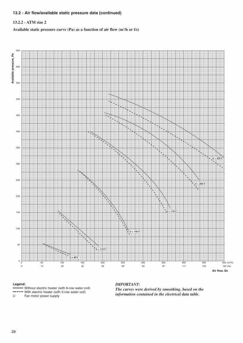
13.2 - Air flow/available static pressure data (continued)
13.2.2 - ATM size 2
Available static pressure curve (Pa) as a function of air flow (m3/h or l/s)
Legend:Without electric heater (with 6-row water coil)With electric heater (with 5-row water coil)
U Fan motor power supply
IMPORTANT:The curves were derived by smoothing, based on theinformation contained in the electrical data table.
29
14 - CONTROLLER
14.1 - Carrier numeric controller
At the top of the range, each ATM is fitted with aprogrammable numeric controller.
The main functions of the controller are:� Controlling room temperature� Raising, lowering and adjusting the angle of Venetian blinds
(optional)� Brightening and dimming light sources (optional)� Selecting comfort or unoccupied mode through a Zone User
Interface or wall thermostat� Controlling ventilation (e.g. by selecting forced ventilation
mode).
NOTE:For further information, please refer to the selectionmanual, installation manual or start-up handbook for theCarrier numeric controller.
14.2 - Carrier electromechanical controller with fanspeed controller
14.2.1 - Speed controller
Inputting a preselected speed
This input gives three speed settings to the speed controller.The speeds are each adjustable by a potentiometer on the faceof the controller.
Setting the speed is achieved when the supply power is appliedto one of the 3 input pre-selections.
Speed control potentiometer ranges are:� low speed 80 to 120 V (± 15 V)� medium speed 110 to 170 V (± 15 V)� high speed 160 to 225 V (± 15 V)
The output ranges are given for a supply network input voltageof 230 V.a.c. (RMS).
Control input 0-10 V.d.c.
This signal has two operating bands:� between 0 and 2 V (± 150 mV), the output is zero� between 2 V (± 150 mV) and 10 V, the output ranges from 80
V (± 15 V) to 225 V (± 15 V), for an input voltage of 230 V.a.c.
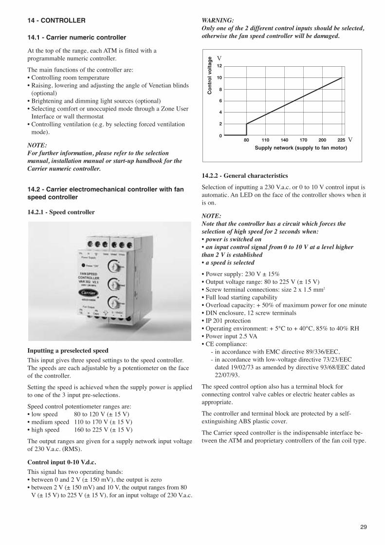
WARNING:Only one of the 2 different control inputs should be selected,otherwise the fan speed controller will be damaged.
14.2.2 - General characteristics
Selection of inputting a 230 V.a.c. or 0 to 10 V control input isautomatic. An LED on the face of the controller shows when itis on.
NOTE:Note that the controller has a circuit which forces theselection of high speed for 2 seconds when:� power is switched on� an input control signal from 0 to 10 V at a level higherthan 2 V is established� a speed is selected
� Power supply: 230 V ± 15%� Output voltage range: 80 to 225 V (± 15 V)� Screw terminal connections: size 2 x 1.5 mm2
� Full load starting capability� Overload capacity: + 50% of maximum power for one minute� DIN enclosure, 12 screw terminals� IP 201 protection� Operating environment: + 5°C to + 40°C, 85% to 40% RH� Power input 2.5 VA� CE compliance:
- in accordance with EMC directive 89/336/EEC,- in accordance with low-voltage directive 73/23/EEC
dated 19/02/73 as amended by directive 93/68/EEC dated22/07/93.
The speed control option also has a terminal block forconnecting control valve cables or electric heater cables asappropriate.
The controller and terminal block are protected by a self-extinguishing ABS plastic cover.
The Carrier speed controller is the indispensable interface be-tween the ATM and proprietary controllers of the fan coil type.
Supply network (supply to fan motor)
Co
ntr
ol v
olt
age V
V
30
14.3 - The various ATM configurations available
Each ATM can be fitted with one or two on/off valves, two orthree ports and flexible water pipes, depending how the unit isconfigured.
a) The ATM is fitted with a speed controller and a 5-rowcooling coil which operates in cooling mode only (2 pipes).
Operates in �cooling� mode only.
This option includes a 2-way on/off valve and two insulatedflexible water pipes.
b) The ATM is fitted with a speed controller and a 5-rowcooling or heating coil (2 pipes with changeover).
Operates in cooling or heating mode. This application is of theheat pump type.
This option includes a 3-way on/off valve, a heating/coolingchangeover switch and two insulated flexible water pipes.
c) The ATM is fitted with a speed controller, a 5-rowcooling coil and a 1-row heating coil (4 pipes).
Operates in cooling and heating mode in sequence.
This option includes 2 on/off valves with 2 ports, and 4flexible water pipes, 2 of which are insulated and 2uninsulated.
d) The ATM is fitted with a speed controller, a 5-rowcooling coil and an electric heater (2 pipes and 2 wires).
Operates in cooling mode or heating mode with electric heaterin sequence.
This option includes a 2-way on/off valve, 2 insulated flexiblewater pipes and 1 power relay for controlling the electricheater.
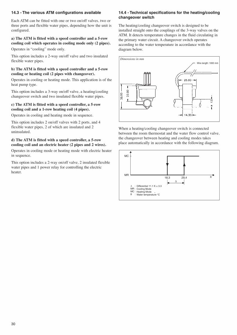
14.4 - Technical specifications for the heating/coolingchangeover switch
The heating/cooling changeover switch is designed to beinstalled straight onto the couplings of the 3-way valves on theATM. It detects temperature changes in the fluid circulating inthe primary water circuit. A changeover switch operatesaccording to the water temperature in accordance with thediagram below.
When a heating/cooling changeover switch is connectedbetween the room thermostat and the water flow control valve,the changeover between heating and cooling modes takesplace automatically in accordance with the following diagram.
Differential 11.1 K ± 3.3Cooling ModeHeating ModeWater temperature °C
Wire length: 1000 mm
Dimensions in mm

31
14.5 - Master/slave control
With the high capacity fan speed controller it is possible to link up to 5 ATMs to one Carrier thermostat with no additional relays.Electrothermal 230 V.a.c. on/off actuators are used. When electric heaters are used with a cooling coil the heater power contactormust be used.
14.5.1 - 4 pipe configurations
Coolingvalve Heating
valve
Fan
Blu
e
Supply:230 V, 50 Hz, 1 phase
3G1, 5 mm2
Protection: T2A
Coolingvalve
Heatingvalve
Blu
e
Fan
Supply:230 V, 50 Hz, 1 phase
3G1, 5 mm2
Protection: T2A
Speed 1 (LS)
Speed 2
Speed 3 (HS)
Cooling valve control
Heating valve control
L: Thermostat supply (230 V a.c.)
N: Thermostat supply (230 V a.c.)

32
Fan
Blu
e
Coolingvalve
Speed 1(LS)
Speed 2
Speed 3 (HS)
Cooling valve open
L: Thermostat supply (230 V a.c.)
N: Thermostat supply (230 V a.c.)
Electricheater
RE
LAY
Electric heater control
Coolingvalve
Fan
Blu
e
Electric heater
RE
LAY
Supply:230 V, 50 Hz, 1 phase 3G2,
5 mm2
Protection: T16A
Supply:230 V, 50 Hz, 1 phase 3G2,
5 mm2
Protection: T16A
14.5 - Master/slave control
14.5.2 - 2 pipe configuration and electric heater

33
14.6 - Wiring diagrams
The ATM unit can be delivered without a control system, that is, without valves or flexible water pipes, but with the fan cablebundle connected to the speed controller and the electric heater connected to the power relay (depending on the configuration). Ifthis option is chosen, the ATM is delivered with a terminal strip and a plastic protective cover.
14.6.1 - 5-row cooling coil (2 pipes)
14.6.2 - 5-row coil with heating/cooling changeover (2 pipe change-over)
Speed 1(LS)
Speed 2
Speed 3 (HS)
Cooling valve open
L: Thermostat supply (230 V a.c.)
N: Thermostat supply (230 V a.c.)
6 x 0.75 mm2
Supply:230 V, 50 Hz, 1 phase 3G1, 5 mm2
Protection: T2A
Fan
Blu
e
Cooling valve
Speed 1(LS)
Speed 2
Speed 3 (HS)
Cooling valve control
L: Thermostat supply (230 V a.c.)
N: Thermostat supply (230 V a.c.)
7 x 0.75 mm2
Supply:230 V, 50 Hz, 1 phase 3G1, 5 mm2
Protection: T2A
Heating valve control
Reversingvalve
Fan
Blu
e

34
14.6.3 - 6-row coil, 5 rows cooling, 1 row heating (4 pipes)
5-row cooling coil and PTC electric heater
Fan
Blu
e
Speed 1(LS)
Speed 2
Speed 3 (HS)
Cooling valve open
L: Thermostat supply (230 V a.c.)
N: Thermostat supply (230 V a.c.)
7 x 0.75 mm2
Supply:230 V, 50 Hz, 1 phase 3G1, 5 mm2
Protection: T2A
Coolingvalve
Heating valve open
Heatingvalve
Fan
Blu
e
Cooling valve
Speed 1(LS)
Speed 2
Speed 3 (HS)
Cooling valve open
L: Thermostat supply (230 V a.c.)
N: Thermostat supply (230 V a.c.)
6 x 0.75 mm2
Supply:230 V, 50 Hz, 1 phase 3G1, 5 mm2
Protection: T2A
Electricheater
RE
LAY
Electric heater control


Order No.: 14243-76, 02.2005 - Supersedes order No.: 14243-79, 12.2000Manufacturer reserves the right to change any product specification without notice.
Manufacturer: Carrier s.a., Montluel, France.Printed in Holland.
Carrier S.A.S. Demonstration SuiteWhether you live in the tropics or in Greenland
Whether you suffer from the heat, from the cold or from lack of airCARRIER has the solution and can show it to you in the demonstration suite
The programmes available
✔✔ simulation of the climate in your region
✔✔ simulation of the heating and cooling loads accordingto your needs
✔✔ measuring, storing and display of the air temperaturesand the air distribution pattern taking into account yourclimatic and architectural constraints - even at climaticextremes
✔✔ optimisation of the physical location of the air terminalsin your building walls or ceilings
✔✔ determination and control of the sound level in everyroom
✔✔ simulation of the control system of your terminals and their link to your BMS system
✔✔ and finally, simulation of how your interior will look, with a floor plan, lights and blinds to ensure true quality
Experience a real preview of your future installation