4316 der kleine uhu v2 en - graupner · 4316_jh_v2 7 / 36 intended use the der kleine uhu model is...
TRANSCRIPT

EN
No. 4316No. 4316.90
Manual
Co
py
rig
ht
© G
rau
pn
er/
SJ
Gm
bH
Free-flight or RC model

2 / 36 4316_jh_V2

Index
Introduction ......................................................................... 6
Service Centre .................................................................... 6
Intended use ...................................................................... 7
Technical data ..................................................................... 7
Declaration of conformity .................................................. 7
Symbols explication ........................................................... 8
Gluing instructions ............................................................. 8
Safety notes ........................................................................ 8
Procedure depending on the version ............................... 9
Required tools and facilities (not included) .................... 10
Assembly steps 1 to 17 for free-flight and RC version . 10
Glue the angle ledge (36) to the wing edge (34) ................ 10
Glue the rear edge of the wing (37) to the angle ledge (36) 11
Profile the wing edge (34) and the rear wing edge (37) with the sanding block(49) ....................................................... 11
Glue the balsa junction part (38) to the profiled wing ......... 12
Refine the upper side of the balsa junction part (38) ......... 12
Glue the winglet (39) ......................................................... 12
Refine the balsa junction part and the lower side of the winglet ............................................................................. 13
Sand the central part of the half-wing until it has a V-form 13
Glue the V-formed half-wing ............................................. 13
Glue the half-wing joint part (40) ....................................... 14
Refine the upper side of the spacers (42) .......................... 14
Draw the fuselage central line ........................................... 15
Center the fuselage base (1) on the central line ................. 15
Glue the bulkheads (3, 4, 5, 6) and the tail boom (2) ......... 15
Glue the bulkheads (7) and the spacers (8) ....................... 16
Glue the fuselage nose (11 - 13) to the fuselage lateral plates (14) ........................................................................ 16
Glue the spacers (9, 10) ................................................... 16
Assembly steps 18 to 21 only for free-flight version ..... 17
Glue the trimming weight (33) and the reinforcement (24) . 17
Glue the V-tail rudders ...................................................... 17
4316_jh_V2

4 / 36 4316_jh_V2
Refine the V-tail halves (32) ............................................... 18
Fix left and right trim rudders ............................................ 18
Assembly steps 18 to 23 only for RC version ................ 19
Glue the servo holder (51) ................................................ 19
Refine the V-tail halves (32) ............................................... 19
Refine the rudders ............................................................ 19
Refine the rudders (32), insert the rudder hinges (53) ........ 20
Glue the rudder hinges (53) .............................................. 20
Glue the V-tail halves (32) ................................................ 21
Assembly step 22 free-flight and 24 RC version ............ 21
Fix the fuselage and the angle template (46) ..................... 21
Assembly step 23 only for free-flight version ................ 22
Glue the V-tail (32) to the tail boom (2) .............................. 22
Assembly steps 25 to 27 only for RC version ................ 22
Glue the V-tail (32) to the tail boom (2) .............................. 22
Glue the bowden cable outer tube (54) ............................. 23
Insert the pushrods (55), glue the rudder horns (52), install the servos ........................................................................ 23
Assembly step 24 free-flight and 28 RC version ............ 24
Sand the fuselage sides untul they are smooth ................. 24
Assembly step 25 free-flight and 29 RC version ............ 24
Glue the fuselage lateral plates (15) and fix them with fixing needles ............................................................................ 24
Assembly step 26 free-flight and 30 RC version ............ 25
Round the fuselage lateral sides, sand the upper side of the fuselage until it is smooth and flat ..................................... 25
Assembly step 27 for free-flight version ........................ 25
Glue the canopy parts (17,18) together and flat, glue the cover part (16) .................................................................. 25
Assembly step 32 only for RC version ............................ 26
Glue the pin (19), glue the canopy cover prts (17,18) together and fix them properly, ......................................... 26
Glue the cover part (16) .................................................... 26
Assembly step 28 free-flight and 33 RC version ............ 26
Round the upper side of the fuselage and the canopy ...... 26
Assembly step 29 free-flight and 34 RC version ............ 27
Glue the towline hook (23) and the pins (21, 22) ............... 27
5 / 36 4316_jh_V2
Assembly step 30 free-flight and 35 RC version ............ 27
Glue the cover part (20), fix the surface with rubber bands (43)................................................................................... 27
Assembly step 31 only for free-flight version ................ 27
Insert the wire (27) for curve control in the fuselage, glue the pin (25) ............................................................................ 28
Assembly step 32 only for free-flight version ................ 28
Bend and glue the trim spring (30) .................................... 28
Assembly step 33 only for free-flight version ................ 29
Insert the wire (27) in the right trim rudder hole and make a knot ................................................................................. 29
Assembly step 36 only for RC version ............................ 29
Install battery and receiver ................................................ 29
Assembly step 34 free-flight and 37 RC version ............ 30
Balance the center of gravity of the model ........................ 30
Assembly step 35 free-flight and 38 RC version ............ 30
Fly, trim ............................................................................ 30
Parts list ............................................................................. 31
Recommended accessories (not included).................... 32
Kit content ......................................................................... 33
Notes on environmental protection ................................ 35
Care and maintenance ..................................................... 35
Warranty certificate .......................................................... 35

IntroductionThank you very much for purchasing the Graupner Der kleine UHU. This free-flight is extremely versatile.
Read this manual carefully to achieve the best results with your Der kleine UHU and first of all to safely control your models. If you experience any trouble during operation, take the instructions to help or ask your dealer or Graupner Service Centre.
Due to technical changes, the information may be changed in this manual without prior notice. Keep updated by regularly checking our own website, www.graupner.de to be always updated with the products and firmware.
This product complies with national and European legal require-ments.
To maintain this condition and to ensure safe operation, you must read and follow this user manual and the safety notes before using the product!
NOTEThis manual is part of the product. It contains important information concerning operation and handling. Keep these instructions for future reference and give it to third person in case you gave the product.
Service CentreGraupner Central ServiceGraupner/SJ GmbH
Henriettenstraße 96
D-73230 Kirchheim/Teck
Servicehotline
� (+49) (0)7021/722-130 Monday - Thursday: 9:15 am - 4:00 pm Friday: 9:15 am - 1:00 pm [email protected]
Graupner USA
3941 Park Dr Suite 20-571
El Dorado Hills, CA 95762
Website: www.graupnerusa.com
Phone: +1 855-572-4746
Email:[email protected]
Graupner in Internet For the service centers outside Germany please refer to our web site www.graupner.de
4316_jh_V2

7 / 36 4316_jh_V2
Intended useThe Der kleine UHU model is an high performance model for the F1H-kleiner UHU free-flight competition class. If desired, the model can be equipped with an RC system. Note that the con-struction manual for the two versions, free-flight or RC model, is different.
Read through this entire manual carefully before you attempt to assemble or use the Der kleine UHU.
For any improper use no warranty or liability is accepted.For any improper use no warranty or liability is accepted.
Graupner/SJ constantly works on the development of all prod-ucts; we reserve the right to change the item, its technology and equipment.
Target groupThe product is not a toy. It is not suitable for children under 14 years. Young people should be overwied and helped by experi-enced model makers while assembling and flying this model. The assembly steps are described as follows and illustrated with assembly photos and sketches.
If you do not have sufficient knowledge about assembling and dealing with aircraft models, please contact an experienced modeler or a model club.
Technical dataWingspan: 1330 mm
Length o.a. approx.: 860 mm
Wing profile: Graupner 6642
Wing area approx. 14,4 dm²
Tailplane area approx. 3,3 dm²
Total surface area approx. 17,7 dm²
Flight weight approx. 195 g
Wing load approx. 11 g/dm²
Declaration of conformityNo. 7892, Servo DS 101
Graupner/SJ declares that the product is conform to EU norms.
EMV 2004/108/EC:
EN 61000-6-1:2007
EN 61000-6-3:2007
8 / 36 4316_jh_V2
Symbols explicationAlways follow the information marked with the CAUTION or WARN-ING symbol. The signal word WARNING indicates the potential for serious injury, the signal word CAUTION indicates possibility of lighter injuries.
The signal words note and caution indicate potential damages to objects.
Gluing instructionsThe included UHU hart is suitable for all of the required gluing processes. Carbon fiber and steel must be sanded before being glued and an hardening period of many hours is required.
Safety notesGeneralThese safety instructions are intended not only to protect the product, but also for your own and other people’s safety. There-fore please read this section very carefully before using the prod-uct!Do not carelessly leave the packaging material lying around, since it might become a dangerous toy for children.
� Persons, including children, with reduced physical, sensory or mental capabilities, or lack of experience or knowledge, or not capable to use safely the Kleine UHU must not use the model without supervision or instruction by a responsible person.
� Operation and use of radio-controlled models needs to be learned! If you have never operated a model of this type before, start carefully and make yourself familiar with the model's reactions to the remote control commands. Pro-ceed responsibly.
� Before you start using the remote control model, you have to check the further relevant laws and regulations.
� The user must be sure, before each use of RC model, about the functional safety and the proper condition of the RC model.
� The insurance is mandatory for all kinds of RC model oper-ation.
� If the model is equipped with RC system (RC version), pay attention to the instruction included with the transmitter.
!
!

9 / 36 4316_jh_V2
Procedure depending on the versionDepending on whether you want to build the free-flight version or the RC version, the approach is different. If the model is assembled as free-flight version, it cannot be converted to RC version. Therefore pay attention to the related assembly steps sequence. (see diagram)
Note
To build the RC version you need the RC conversion kit No. 4616.90 (not included in the kit).
Frei�ugmodell RC-Modell
1 - 17
18 - 21 18 - 23
22
1 - 17
24
23
24 28
25
26
27
25 29
31
26 30
27 31
32
28 33
29 34
30 35
33
36
34 37
35 38
32

10 / 36 4316_jh_V2
Required tools and facilities (not included)
Assembly steps 1 to 17 for free-flight and RC version
Glue the angle ledge (36) to the wing edge (34)
Note:
Note that a left and a right half-wing are included. In order to let the wing panels have approximately the same weight, join the balsa components accordingly. Pair the heavier wing ledge (34) or (35) with the lighter parts (36) and (37). Immediately remove the excessing glue.
36
34
No. 531.19
No. 717
No.504.C.10,0
1.
1. Pencil
2. Balsa cutter No. 980
3. Sanding block (included)
4. Ruler
5. Building board No.504.C.10,0
6. Fixing needles No717
7. Adhesive tape No. 531.19
8. Balsa plane No 737
9. Small flat pliers
10. Scissors
11. Cyano glue No.5821*
12. Activator No 953.150*
*only for RC version
1 2
34
No. 531.19
9
10
8 7
11 / 36 4316_jh_V2
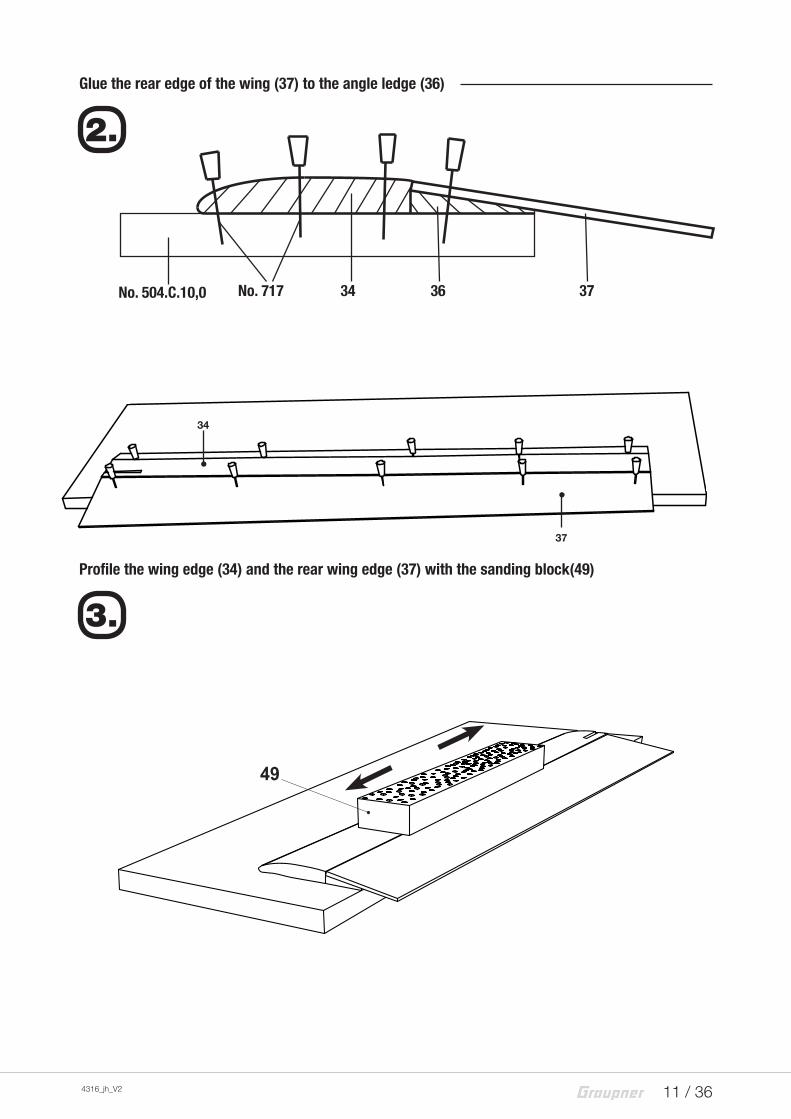
Glue the rear edge of the wing (37) to the angle ledge (36)
Profile the wing edge (34) and the rear wing edge (37) with the sanding block(49)
No. 504.C.10,0 No. 717 34 36 37
2.
49
3.
37
34

12 / 36 4316_jh_V2
Glue the balsa junction part (38) to the profiled wing
Refine the upper side of the balsa junction part (38)
Note:
Refine the balsa junction parts with the balsa cutter first.
CAUTIONINJURY RISK, MOVE THE CUTTER ALWAYS IN THE OPPOSITE DIREC-TION OF YOUR FINGERS AND HANDS.
Then sand it parallelly to the upper wing side using the sanding block. Therefore the junction part will automatically get the curved outline.
Glue the winglet (39)
4.
5.
!
6.
3834
37
38 38
39

13 / 36 4316_jh_V2
Refine the balsa junction part and the lower side of the winglet
Sand the central part of the half-wing until it has a V-form
Glue the V-formed half-wing
9.
7.
8.
40 mm
47
4°
No. 531.19

14 / 36 4316_jh_V2
Glue the wing binding part (40)
Refine the upper side of the spacers (42)
10.
42
40
41
No. 531.19

15 / 36 4316_jh_V2
Draw the fuselage central line
Center the fuselage base (1) on the central line
Glue the bulkheads (3, 4, 5, 6) and the tail boom (2)
Note
Check the perpendicular position of the bulkheads with the angle template (48), do not glue the template. Roughen the part of the carbon fiber tube that is going to be glued.
12.
13.
14.
1
2
48
No. 531.19
45
6
3

16 / 36 4316_jh_V2
Glue the bulkheads (7) and the spacers (8)
Glue the fuselage nose (11 - 13) to the fuselage lateral plates (14)
Glue the spacers (9, 10)
15.
16.
17.
87
13
12
11
14
10
10
9

17 / 36 4316_jh_V2
Assembly steps 18 to 21 only for free-flight version
Glue the trimming weight (33) and the reinforcement (24)
Glue the V-tail rudders
18.
19.
33
24
No. 531.19

18 / 36 4316_jh_V2
Refine the V-tail halves (32)
Fix left and right trim rudders
20.
21.
2832
28
32 28
28
2931
3131
32 32
29
46

19 / 36 4316_jh_V2
Assembly steps 18 to 23 only for RC version
Glue the servo holder (51)
Refine the V-tail halves (32)
Refine the rudders
20.
18.
19.
46
51

20 / 36 4316_jh_V2
Refine the rudders (32), insert the rudder hinges (53)
Glue the rudder hinges (53)
Note:
Fix the V-tail parts (32) and the inserted rudder hinges (53) by piercing them with the fixing needles. Fill the holes that remain after removing the needles with cyano glue. Immediately remove the excessing cyano glue.
3.
2.
32 53
4.
53
1.
53
21.
22.
1.2.3.

21 / 36 4316_jh_V2
Glue the V-tail halves (32)
Assembly step 22 free-flight and 24 RC version
Fix the fuselage and the angle template (46)
45
No. 531.19
1.
2.
No. 531.19
23.
46
46

22 / 36 4316_jh_V2
Assembly step 23 only for free-flight version
Glue the V-tail (32) to the tail boom (2)
Assembly steps 25 to 27 only for RC version
Glue the V-tail (32) to the tail boom (2)
Assembly step like by the free-flight version (see above), only the distance of the V-tail parts is different. (see the sketch).
2
45
20 mm
25.

23 / 36 4316_jh_V2
Glue the bowden cable outer tube (54)
Insert the pushrods (55), glue the rudder horns (52), install the servos
26.
27.
5454
54
56
55
5252
55

24 / 36 4316_jh_V2
Assembly step 24 free-flight and 28 RC version
Sand the fuselage sides until they are smooth
Assembly step 25 free-flight and 29 RC version
Glue the fuselage lateral plates (15) and fix them with fixing needles
Note:
Insert the pins (21 + 22) just to center the side parts. after hav-ing fixed the side parts, remove the pins before the glue has hardened.
1010
2122

25 / 36 4316_jh_V2
Assembly step 26 free-flight and 30 RC version
Round the fuselage lateral sides, sand the upper side of the fuselage until it is smooth and flat
Note:
Firstly refine the fuselage lower part with the balsa cutter or with the balsa plane.
CAUTIONINJURY RISK, MOVE THE CUTTER ALWAYS IN THE OPPOSITE DIREC-TION OF YOUR FINGERS AND HANDS.
Then round it with the sanding block. (see step A-A)
Then sand the upper part of the fuselage until it is flat.
Assembly step 27 for free-flight version
Glue the canopy parts (17,18) together and flat, glue the cover part (16)
!
16 17.18

26 / 36 4316_jh_V2
Assembly step 32 only for RC version
Glue the pin (19), glue the canopy cover parts (17,18) together and fix them properly,Glue the cover part (16)
Assembly step 28 free-flight and 33 RC version
Round the upper side of the fuselage and the canopy
4x
5 mm
19
1.
2.
3.

27 / 36 4316_jh_V2
Assembly step 29 free-flight and 34 RC version
Glue the towline hook (23) and the pins (21, 22)
Assembly step 30 free-flight and 35 RC version
Glue the cover part (20), fix the surface with rubber bands (43)
Assembly step 31 only for free-flight version
Note
The curve control function in the free-flight version:
Starting point is a trimmed model that flies straight on. The trim rudder (28) is has that scope. After the towing start the curve control is released through an eyelet on the towing start ring (see separate towing start manual) and the model will start to circle because the right trim rudder is pushed under by the trim spring (30) of about 5°.
Shorten the wire (27) from accessory No. 242.
The manual of the "towing starter" are available in the web page of the product.
20
43
23
2222

28 / 36 4316_jh_V2
Insert the wire (27) for curve control in the fuselage, glue the pin (25)
Assembly step 32 only for free-flight version
Bend and glue the trim spring (30)
25 27
2625
27
27
ca. 10°
10
535 3025
29 / 36 4316_jh_V2
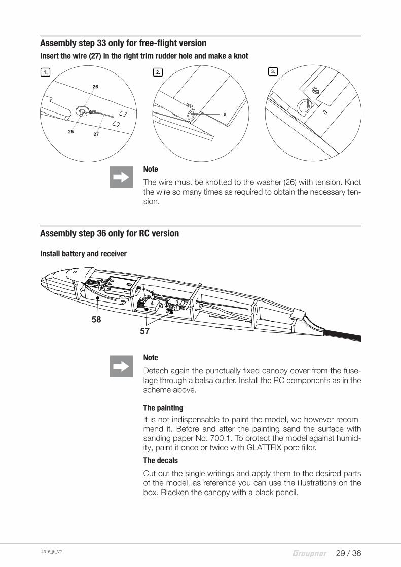
Assembly step 33 only for free-flight versionInsert the wire (27) in the right trim rudder hole and make a knot
Note
The wire must be knotted to the washer (26) with tension. Knot the wire so many times as required to obtain the necessary ten-sion.
Assembly step 36 only for RC version
Install battery and receiver
Note
Detach again the punctually fixed canopy cover from the fuse-lage through a balsa cutter. Install the RC components as in the scheme above.
The paintingIt is not indispensable to paint the model, we however recom-mend it. Before and after the painting sand the surface with sanding paper No. 700.1. To protect the model against humid-ity, paint it once or twice with GLATTFIX pore filler.
The decals
Cut out the single writings and apply them to the desired parts of the model, as reference you can use the illustrations on the box. Blacken the canopy with a black pencil.
1. 2. 3.
26
25 27
5857
34

30 / 36 4316_jh_V2
Assembly step 34 free-flight and 37 RC version
Balance the center of gravity of the model
Assembly step 35 free-flight and 38 RC version
Fly, trim
1. 2.
45 mm
No. 3663.50
1
No. 3663.50
2
No. 3663.50
3
31 / 36 4316_jh_V2
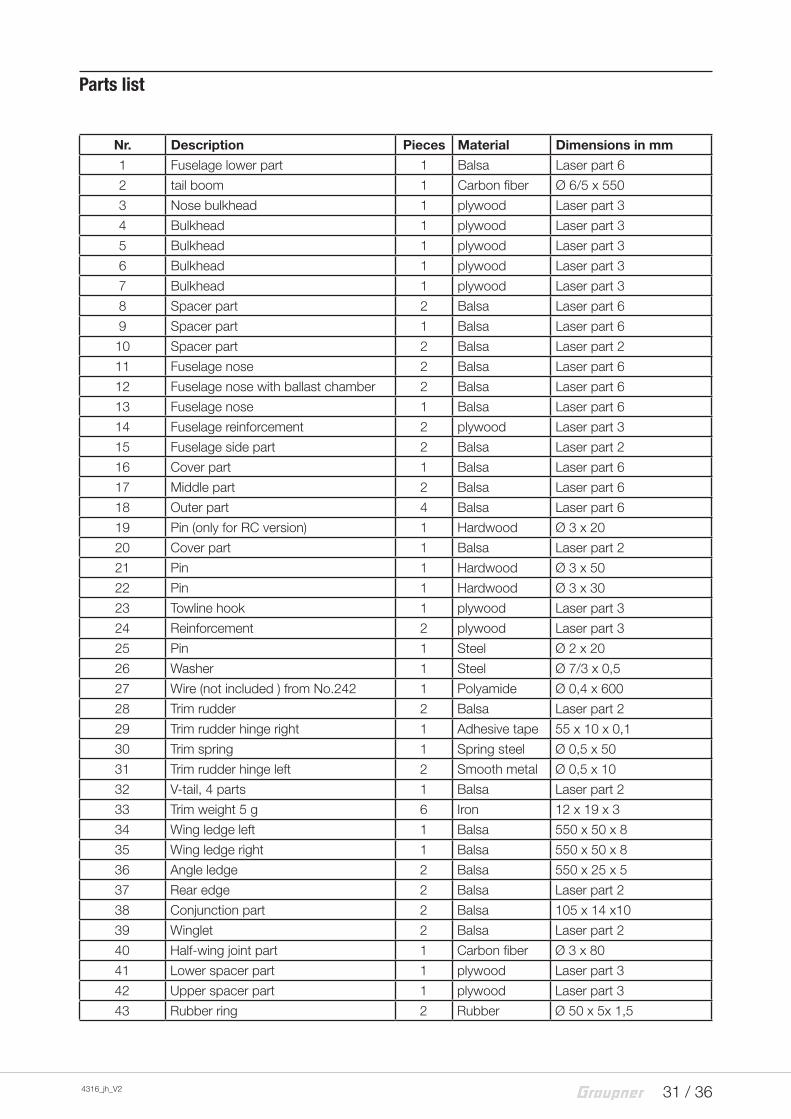
Nr. Description Pieces Material Dimensions in mm
1 Fuselage lower part 1 Balsa Laser part 6
2 tail boom 1 Carbon fiber Ø 6/5 x 550
3 Nose bulkhead 1 plywood Laser part 3
4 Bulkhead 1 plywood Laser part 3
5 Bulkhead 1 plywood Laser part 3
6 Bulkhead 1 plywood Laser part 3
7 Bulkhead 1 plywood Laser part 3
8 Spacer part 2 Balsa Laser part 6
9 Spacer part 1 Balsa Laser part 6
10 Spacer part 2 Balsa Laser part 2
11 Fuselage nose 2 Balsa Laser part 6
12 Fuselage nose with ballast chamber 2 Balsa Laser part 6
13 Fuselage nose 1 Balsa Laser part 6
14 Fuselage reinforcement 2 plywood Laser part 3
15 Fuselage side part 2 Balsa Laser part 2
16 Cover part 1 Balsa Laser part 6
17 Middle part 2 Balsa Laser part 6
18 Outer part 4 Balsa Laser part 6
19 Pin (only for RC version) 1 Hardwood Ø 3 x 20
20 Cover part 1 Balsa Laser part 2
21 Pin 1 Hardwood Ø 3 x 50
22 Pin 1 Hardwood Ø 3 x 30
23 Towline hook 1 plywood Laser part 3
24 Reinforcement 2 plywood Laser part 3
25 Pin 1 Steel Ø 2 x 20
26 Washer 1 Steel Ø 7/3 x 0,5
27 Wire (not included ) from No.242 1 Polyamide Ø 0,4 x 600
28 Trim rudder 2 Balsa Laser part 2
29 Trim rudder hinge right 1 Adhesive tape 55 x 10 x 0,1
30 Trim spring 1 Spring steel Ø 0,5 x 50
31 Trim rudder hinge left 2 Smooth metal Ø 0,5 x 10
32 V-tail, 4 parts 1 Balsa Laser part 2
33 Trim weight 5 g 6 Iron 12 x 19 x 3
34 Wing ledge left 1 Balsa 550 x 50 x 8
35 Wing ledge right 1 Balsa 550 x 50 x 8
36 Angle ledge 2 Balsa 550 x 25 x 5
37 Rear edge 2 Balsa Laser part 2
38 Conjunction part 2 Balsa 105 x 14 x10
39 Winglet 2 Balsa Laser part 2
40 Half-wing joint part 1 Carbon fiber Ø 3 x 80
41 Lower spacer part 1 plywood Laser part 3
42 Upper spacer part 1 plywood Laser part 3
43 Rubber ring 2 Rubber Ø 50 x 5x 1,5
Parts list

32 / 36 4316_jh_V2
44 Decals sheet1
Self-adhesive foil
180 x 55 x 0,1
45 Angle template 100° 1 Balsa Laser part 6
46 Angle template 40° 2 Balsa Laser part 2
47 Angle template 94° 1 plywood Laser part 3
48 Angle template 90° 1 plywood Laser part 3
49 Sanding block 1 Hardwood 125 x 40 x 20
50 UHU hart 1 Hard glue 7 g
Parts list No. 4316.90
Description Pieces Material Dimensions in mm
51 Servo holder 1 Balsa Laser part 2
52 Rudder horn 2 plywood Laser part 1,2
53 Rudder hinge 6 Plastic 12 x 7x 0,2
54 Bowden pushrod tube 2 Plastic Ø 1,85/0,9 x 700
55 Rudder wire 2 Steel Ø 0,5 x 750
56 Blocking part 2 Plastic Ø 1,85/0,9 x 5
57 Servo DS 101 2 Finished unit 17 x 8,5 x 18
58 Receiver battery 4/300 4,8 V 300 mAh 1 NiMh 58 x 18 x 15
Recommended accessories (not included) � No. S1001.DE Transmitter set mz-10 HoTT � No. 4316.90 RC conversion kit � No. 6427 Battery charger Multicharger 3 NiMH � No. 45.3 Towline elastic wire � No. 19 Wire parachute � No. 242 Towline � No. 569 Tow start rings � No. 3663.50 Trim ballast � No. 207 Glattfix pore filler � No. 208 Brush � No. 1409 Spannfix-thinner � No. 700.1 Sanding paper

33 / 36 4316_jh_V2
16
13
45
1818
9.
1112
8
81
1818
1717
1112
A
C5
4
24
1414
4847
2423
36
7
4241
D
10
10
15
15
20
E
32 39
39 46
32 28
Kit content
A
C
D
E / 2x
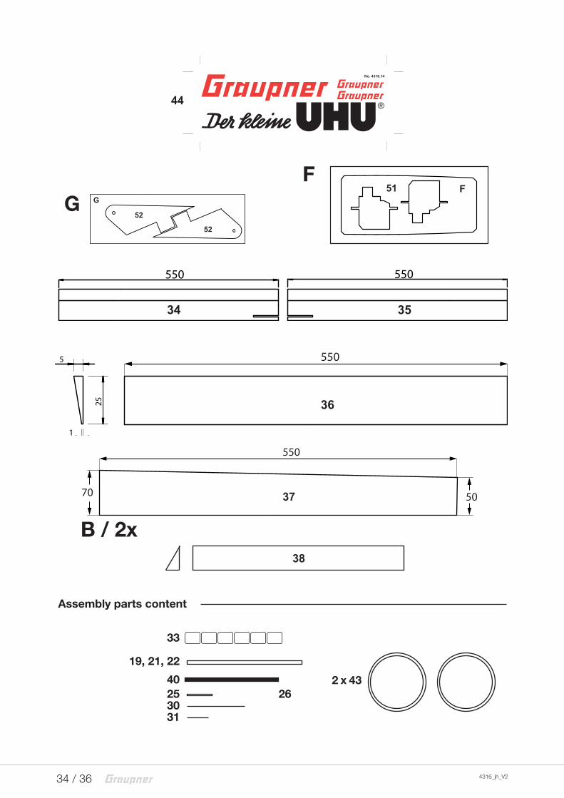
34 / 36 4316_jh_V2
3
50
18
10
550
40
550
8
4
34 35
5
1
25
550
36
550
3770 50
G
52
52
GF51
F
33
19, 21, 22
4025 263031
2 x 43
Assembly parts content
38
44
B / 2x

35 / 36 4316_jh_V2
Notes on environmental protection
Disposal notesThis symbol on the product, user manual or packaging indicates that this product must not be disposed of with other household waste at the end of its life. It must be handed over to the appli-cable collection point for the recycling of electrical and electronic equipment.
The materials are recyclable as marked. By recycling, material reusing or other forms of scrap usage you are making an import-ant contribution to environmental protection.
Batteries and accumulators must be removed from the device and disposed of at an appropriate collection point. Please inquire if necessary from the local authority for the appropriate disposal site.
Care and maintenance
Notes on careThe product does not need any maintenance, it works so as it is without any special care. In your own interests protect it from dust, dirt and moisture.
WarrantyThe Graupner, Henriettenstrassee 96, 73230 Kirchheim/Teck grants from the date of purchase of this product for a period of 24 months. The warranty applies only to the material or opera-tional defects already existing when you purchased the item. Damage due to misuse, wear, overloading, incorrect accesso-ries or improper handling are excluded from the guarantee. The legal rights and claims are not affected by this guarantee. Please check exactly defects before a claim or send the product, because we have to ask you to pay shipping costs if the item is free from defects.
The present construction or user manual is for informational pur-poses only and may be changed without prior notice. The cur-rent version can be found on the Internet at www.graupner.de on the relevant product page. In addition, the company Graupner has no responsibility or liability for any errors or inaccuracies that may appear in construction or operation manuals.
No liability can be accepted for printing errors.
P
