46-115 b73 and series 75 sealed external cage liquid level...
TRANSCRIPT

D E S C R I P T I O N
Sealed external cage type level switches are completely
self-contained units designed for side mounting to a tank
or vessel with threaded or flanged pipe connections.
These units are an industry standard in petroleum
refineries and chemical plants. Thousands of these
switches are in daily service throughout the world.
A P P L I C A T I O N S
• Accumulators • Flash tanks
• Receivers • Knockout drums
• Flare pots • Storage tanks
• Scrubbers • Separators
• Oil refineries • Chemical processing plants
• Steam and electric generating stations
Model B73 & Series 75
Sealed External Cage
Liquid Level Switches
1
Pivot
ReturnSpring
Process LiquidProcess Liquid
Rising Level Falling Level
6
5
4
3
2
T E C H N O L O G Y
A permanent magnet➀ is attached to a pivoted switch
actuator and adjustment screw ➁. As the float ➂ rises
following the liquid level, it raises the attraction sleeve
➃ into the field of the magnet, which then snaps
against the non-magnetic enclosing tube ➄, actuating
the switch ≈. The enclosing tube provides a static
pressure boundary between the switch mechanism and
the process. On a falling level, an inconel spring retracts
the magnet, deactivating the switch.
F E A T U R E S
• Carbon steel or stainless steel welded float chamber
• Service pressures up to 2240 psig (154 bar)
• Process temperatures up to +1000 °F (+538 °C);Consult factory for process temperatures up to+1200 °F (+650 °C)
• Specific gravity ratings as low as 0.32
• Available switch styles including dry contact, hermetically sealed and pneumatic
• Single or multiple switch mechanisms available
• Available switch enclosures include:
NEMA 1 carbon steel for pneumatics
TYPE 4X/7/9 Class I, Div. 1 Groups C & D orGroups B, C & D polymer coated aluminum
• 1", 11⁄2", or 2" tank connections available in eitherNPT, socket weld, flanged side/side or flangedside/bottom construction
• Optional high temperature insulation available.See bulletin 41-106.

2
AGENCY APPROVED MODEL AREA CLASSIFICATION
FM All with an electric switch mechanism and a housing Class I, Div 1, Groups C & Dlisted as TYPE 4X/7/9 Class II, Div 1, Groups E, F & G
All with an electric switch mechanism and a housing Class I, Div 1, Groups B, C & Dlisted as TYPE 4X/7/9 Class I, Div 1, Group B Class II, Div 1, Groups E, F & G
CSA All with a Series HS, F, 8 or 9 electric switch Class I, Div 2, Groups A, B, C & Dmechanism and a housing listed as CSA TYPE 4X
All with an electric switch mechanism and a housing Class I, Div 1, Groups C & Dlisted as TYPE 4X/7/9 Class II, Div 1, Groups E, F & G
All with an electric switch mechanism and a housing Class I, Div 1, Groups B, C & Dlisted as TYPE 4X/7/9 Class I, Div 1, Group B Class II, Div 1, Groups E, F & G
ATEX / IEC Ex ➁ All with an electric switch mechanism and an ATEX II 2 G EEx D IIC T6ATEX housing ➀ 94/9/EC
IEC Ex Ex d IIc T6IP66
CE Low Voltage Directives 2006/95/EC Installation Category IIPer Harmonized Standard: Pollution Degree 2EN 61010-1/1993 & Amendment No. 1
AG E N C Y A P P R O V A L S
➀ Models with two HS switches are not ATEX approved.
➁ IEC Installation Instructions: The cable entry and closing devices shall be Ex d certified suitable for the conditions of use and correctly installed.
For ambient temperatures above +55 °C or for process temperatures above +150 °C, suitable heat resistant cables shall be used.
Heat extensions (between process connection and housing) shall never be insulated.
Special conditions for safe use:
When the equipment is installed in process temperatures higher than +85 °C the temperature classification must be reduced according tothe following table as per IEC60079-0.
Maximum ProcessTemperature
TemperatureClassification
< 85 °C T6< 100 °C T5< 135 °C T4< 200 °C T3< 300 °C T2< 450 °C T1
These units are in conformity with IECEx KEM 05.0020XClassification Ex d IIC T6Tambient -40 °C to +70 °C
BAS IC E LECTR ICAL RAT INGS
VoltageSwitch Series and Non-Inductive Ampere Rating
B C D F HS R 8 9
120 VAC 15.00 15.00 10.00 2.50 5.00 1.00 1.00 —
240 VAC 15.00 15.00 — — 5.00 1.00 — —
24 VDC 6.00 6.00 10.00 4.00 5.00 1.00 3.00 0.50
120 VDC 0.50 1.00 10.00 0.30 0.50 0.40 — —
240 VDC 0.25 0.50 3.00 — 0.25 — — —
CARBON STEEL CHAMBERS WITH 11⁄2-INCH CONNECTIONSINCHES MILLIMETERS
D I M E N S I O N A L S P E C I F I C A T I O N S
Min.SG
NPT &Socket Weld
FlangedUpper Side/Btm
FlangedSide/Side
ActuatingLevels
NPT &Socket Weld
FlangedUpper Side/Btm
FlangedSide/Side
ActuatingLevels
A B C A B C A B C HL LL A B C A B C A B C HL LL
B75 0.678.94 4.22 23.06 12.56 7.69 26.69 13.21 7.69 27.34
1.93 2.61227 107 586 319 195 678 336 195 694
49 66
C75 0.55 1.93 2.61 49 66
F75 0.55 11.06 5.75 26.19 14.78 9.19 29.92 15.39 9.19 30.53 1.08 1.66 281 146 665 375 233 760 391 233 775 27 42
G75 0.539.62 4.75 24.09 13.31 8.19 27.75 13.96 8.19 28.42
1.59 2.25244 121 612 338 208 705 355 208 722
40 57
J75 0.48 2.23 2.95 56 74
K75 0.39 12.06 5.75 27.14 15.56 9.19 30.64 16.21 9.19 31.29 1.77 2.39 306 146 689 395 233 778 412 233 795 44 60
L75 0.40 9.62 4.75 24.09 13.31 8.19 27.75 13.96 8.19 28.42 1.78 2.52 244 121 612 338 208 705 355 208 722 44 64
N75 0.32 12.06 5.75 27.14 15.56 9.19 30.64 16.21 9.19 31.29 1.81 2.49 306 146 689 395 233 778 412 233 306 45 63
S75 0.60 Consult Factory n/a n/a Consult Factory n/a n/a
V75 0.74 8.82 4.22 23.20 12.56 7.68 26.94 13.21 7.68 27.79 1.94 2.69 224 107 589 319 195 684 336 195 706 49 68
Z75 0.68 9.51 4.75 24.09 13.31 8.18 27.89 13.96 8.18 28.54 1.69 2.59 242 121 612 338 208 708 355 208 725 43 66
➁➀
➁
Levels are ±0.25" (6 mm)

3
F
E
D
B
A
C
HLLL
Series 75
Threaded and Socket Weld
Upper Side/Bottom
E
D
A
B
C
F
HLLL
Series 75
Flanged Upper Side/Bottom
F
E
D
C
A
B
HLLL
Series 75
Flanged Side/Side
CARBON STEEL CHAMBERS WITH 2-INCH CONNECTIONSINCHES MILLIMETERS
Conduit Connections F
Electrical SwitchesTYPE 4X/7/9: 1" NPTGroup B: 1" NPT
Pneumatic SwitchesNEMA 1: 1⁄4" NPT
➀ Min S.G. given is for single switch units with –1 materials of construction only. Consult factory for other configurations.
➁ Switch actuating levels (HL & LL) are given for minimum specificgravity materials of construction –1 and single switch units.Consult factory for other configurations.
NOTES:
1. Standard process connections are a combination of 1" NPT and1" socket weld coupling.
2. Allow overhead clearance of 10 inches (254 mm) for cover removal.
3. All housings rotatable 360 degrees.
Housing D E
NEMA 1 4.70 5.00(119) (127)
TYPE 4X/7/9 5.93 3.87Group B (151) (98)
Min.SG
NPT &Socket Weld
FlangedUpper Side/Btm
FlangedSide/Side
ActuatingLevels
NPT &Socket Weld
FlangedUpper Side/Btm
FlangedSide/Side
ActuatingLevels
A B C A B C A B C HL LL A B C A B C A B C HL LL
B75 0.678.69 4.34 23.20 12.56 7.69 26.07 13.21 7.69 27.72
1.48 2.16221 110 589 319 195 662 336 195 704
37 54
C75 0.55 1.64 2.36 41 59
F75 0.55 10.94 5.88 26.32 14.78 9.19 30.16 15.39 9.19 30.77 0.78 1.36 278 149 669 375 233 766 391 233 782 19 34
G75 0.539.50 4.88 24.21 13.31 8.19 28.02 13.96 8.19 28.67
1.31 1.97241 124 615 338 208 712 355 208 728
33 50
J75 0.48 1.95 2.67 49 67
K75 0.39 11.94 5.88 27.32 15.56 9.19 30.94 16.21 9.19 31.59 1.59 2.21 303 149 694 395 233 786 412 233 802 40 56
L75 0.40 9.50 4.88 24.21 13.31 8.19 28.02 13.96 8.19 28.67 1.50 2.24 241 124 615 338 208 712 355 208 728 38 56
N75 0.32 11.94 5.88 27.32 15.56 9.19 30.94 16.21 9.19 31.59 1.63 2.31 303 149 694 395 233 786 412 233 802 40 58
S75 0.60 Consult Factory n/a n/a Consult Factory n/a n/a
V75 0.74 8.49 4.34 23.27 12.56 7.68 27.34 13.21 7.68 27.99 1.88 2.63 216 110 591 319 195 694 336 195 711 48 67
Z75 0.68 9.31 4.87 24.16 13.31 8.18 28.16 13.96 8.18 28.81 1.44 2.25 236 124 614 338 208 715 355 208 732 37 57
➁➀
➁
Levels are ±0.25" (6 mm)

Conduit Connections F
Electrical SwitchesTYPE 4X/7/9: 1" NPTGroup B: 1" NPT
Pneumatic SwitchesNEMA 1: 1⁄4" NPT
➀ Min S.G. given is for single switch units with –1 materials of con-struction only. Consult factory for other configurations.
➁ Switch actuating levels (HL & LL) are given for minimum specificgravity materials of construction –1 and single switch units.Consult factory for other configurations.
➂ 304 Stainless steel only.
➃ 316 Stainless steel only.
➄ These dimensions increase by 2.19 inches (55 mm) with SeriesHS switches with terminal blocks.
NOTES:
1. Standard process connections are a combination of 1" NPT and1" socket weld coupling.
2. Allow overhead clearance of 10 inches (254 mm) for cover removal.
3. All housings rotatable 360 degrees.
STAINLESS STEEL CHAMBERS WITH 1-INCH CONNECTIONSINCHES MILLIMETERS
4
D I M E N S I O N A L S P E C I F I C A T I O N S
CARBON STEEL CHAMBERS WITH 1-INCH CONNECTIONSINCHES MILLIMETERS
Housing D E
NEMA 1 4.70 5.00(119) (127)
TYPE 4X/7/9 5.93 3.87Group B (151) (98)
Min.SG
NPT &Socket Weld
FlangedUpper Side/Btm
FlangedSide/Side
ActuatingLevels
NPT &Socket Weld
FlangedUpper Side/Btm
FlangedSide/Side
ActuatingLevels
A B C A B C A B C HL LL A B C A B C A B C HL LL
B73 0.59 6.36 3.34 17.44 9.25 6.25 20.32 9.90 6.25 21.00 1.22 2.10 151 84 442 235 159 515 251 159 532 30 53
B75 0.678.69 3.80 22.69 11.56 6.69 25.56 12.21 6.69 26.21
2.56 3.24221 97 576 294 170 649 310 170 666
65 82
C75 0.55 2.72 3.44 69 87
F75 0.55 10.91 5.33 24.91 13.78 8.19 27.78 14.39 8.19 28.39 1.76 2.35 277 135 633 350 208 706 366 208 721 44 59
G75 0.539.44 4.33 23.44 12.31 7.19 26.31 12.96 7.19 26.96
2.25 2.92240 110 595 313 183 668 329 183 685
57 74
J75 0.48 2.90 3.62 73 91
K75 0.39 11.69 5.33 25.69 14.56 8.19 28.56 15.21 8.19 29.21 2.15 2.77 297 135 653 370 208 754 386 208 742 54 70
L75 0.40 9.44 4.33 23.44 12.31 7.19 26.31 12.96 7.19 26.96 2.45 3.19 240 110 595 313 183 668 329 183 685 62 81
N75 0.32 11.69 5.33 25.69 14.56 8.19 28.56 15.21 8.19 29.21 2.17 2.86 297 135 653 370 208 754 386 208 742 55 72
S75 0.60 11.16 5.33 27.06 Consult Factory 2.13 2.78 283 135 687 Consult Factory 54 70
V75 0.74 9.02 4.15 23.27 11.56 6.68 25.81 12.21 6.68 26.46 2.63 3.38 229 105 591 294 170 656 313 170 672 69 86
Z75 0.68 9.77 4.68 24.16 12.31 7.18 26.70 12.96 7.18 27.35 2.38 3.19 248 119 614 313 182 678 329 182 695 60 81
➁➀
➁
Min.SG
NPT &Socket Weld
FlangedUpper Side/Btm
FlangedSide/Side
ActuatingLevels
NPT &Socket Weld
FlangedUpper Side/Btm
FlangedSide/Side
ActuatingLevels
A B C A B C A B C HL LL A B C A B C A B C HL LL
B73 0.59 6.36 2.83 17.44 9.25 6.25 20.32 9.90 6.25 21.00 1.22 2.10 151 72 442 235 159 515 251 159 532 30 53
C75 0.60 8.50 3.61 22.06 11.56 6.68 25.12 12.21 6.68 25.75 2.75 3.62 216 92 560 294 170 638 310 170 654 70 92
J75 0.57 9.25 3.61 23.06 12.31 6.68 26.12 12.96 6.68 26.75 2.93 3.78 235 92 586 313 170 663 329 170 679 74 96
O75 0.85 8.50 2.71 21.87 11.56 5.68 24.93 12.21 5.68 25.62 2.44 3.50 216 69 555 294 144 633 310 144 651 62 89
O75 0.85 8.50 2.59 21.56 11.56 5.56 24.62 12.21 5.56 25.43 2.44 3.50 216 66 548 294 141 625 310 141 646 62 89
P75 0.75 8.50 3.09 21.93 11.56 6.12 25.00 12.21 6.12 25.68 2.56 3.50 216 76 557 294 155 635 310 155 652 65 89
➃
➂
➀➁ ➁
Levels are ±0.25" (6 mm)
Levels are ±0.25" (6 mm)

5
D I M E N S I O N A L S P E C I F I C A T I O N S
I N C H E S ( m m )
F
E
D
B
A
C
HLLL
E
D
A
B
C
F
HLLL
F
E
D
C
A
B
HLLL
Series 75
Threaded and Socket Weld
Upper Side/Bottom
Series 75
Flanged Upper Side/Bottom
Series 75
Flanged Side/Side
plugged
6.25(158)
F
B
F
HLLL
➃
➄
A
C
D
E6.25(158)
F
F
HLLL
➃
➄
plugged
B
D
A
C
E
plugged
6.25(158)
F
F
HLLL
➃
➄
B
D
A
C
E
Model B73
Flanged Side/Side
Model B73
Flanged Upper Side/Bottom
Model B73
Threaded and Socket Weld
Upper Side/Bottom
6
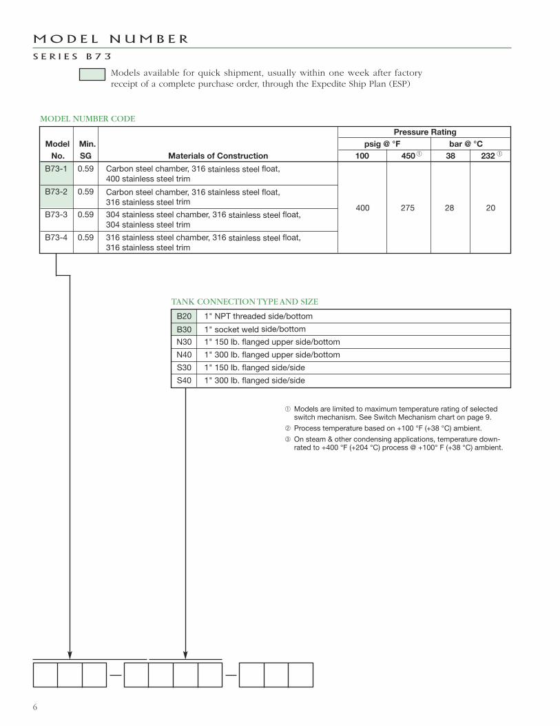
Pressure Rating
Model Min. psig @ °F bar @ °C
No. SG Materials of Construction 100 450 38 232
B73-1 0.59 Carbon steel chamber, 316 stainless steel float,400 stainless steel trim
B73-2 0.59 Carbon steel chamber, 316 stainless steel float,316 stainless steel trim
400 275 28 20B73-3 0.59 304 stainless steel chamber, 316 stainless steel float,
304 stainless steel trim
B73-4 0.59 316 stainless steel chamber, 316 stainless steel float,316 stainless steel trim
Models available for quick shipment, usually within one week after factoryreceipt of a complete purchase order, through the Expedite Ship Plan (ESP)
MODEL NUMBER CODE
B20 1" NPT threaded side/bottom
B30 1" socket weld side/bottom
N30 1" 150 lb. flanged upper side/bottom
N40 1" 300 lb. flanged upper side/bottom
S30 1" 150 lb. flanged side/side
S40 1" 300 lb. flanged side/side
TANK CONNECTION TYPE AND SIZE
MOD E L N UM B E R
S E R I E S B 7 3
➀ ➀
➀ Models are limited to maximum temperature rating of selectedswitch mechanism. See Switch Mechanism chart on page 9.
➁ Process temperature based on +100 °F (+38 °C) ambient.
➂ On steam & other condensing applications, temperature down-rated to +400 °F (+204 °C) process @ +100° F (+38 °C) ambient.

7
Maximum Maximum Bleed Models withSupply Process Orifice Material of Construction
SwitchPressure Temperature Diameter Code 1 Code 2, 3 or 4
Descriptionpsig bar ° F ° C inches mm NEMA 1 NEMA 1
Series J100 7 400 204 .063 1.6 JDG JDE
Bleed Type 60 4 400 204 .094 2.3 JEG JEE60 4 450 232 .055 1.4 — JFE
Series K 100 7 400 204 — — — KOENon-Bleed 40 3 400 204 — — KOG —
PNEUMATIC SWITCH MECHANISM AND ENCLOSURE
ELECTRIC SWITCH MECHANISM AND ENCLOSURE
Switch Description
➁Process
TemperatureRange °F (°C)
One Set PointContacts
Model B73-1 Only Models B73-2, B73-3, B73-4
TYPE 4X/7/9 Aluminum Enclosure
Class I, Div 1GroupsC & D
Class I, Div 1GroupsB, C & D II 2 G EEx
D IIC T6
Class I, Div 1GroupsC & D
Class I, Div 1GroupsB, C & D II 2 G EEx
D IIC T6
Series B Snap -40 to +250(-40 to +121)
SPDT BKP
BNP
BKT
BNT
BAC
BBC
BKQ
BNQ
BKS
BNS
BA9
BB9DPDT
Series C Snap -40 to +450(-40 to +232)
SPDT CKP
CNP
CKT
CNT
CAC
CBC
CKQ
CNQ
CKS
CNS
CA9
CB9DPDT
Series D Snap -40 to +250(-40 to +121)
SPDTn/a
DKQ
DNQ
DKS
DNS
DA9
DB9DPDT
Series FHermetically Sealed Snap
-50 to +450(-46 to +232)
SPDT FKP FKT FAC FKQ FKS FA9
DPDT FNP FNT FBC FNQ FNS FB9
Series HSHermetically Sealed 5 amp
Snap with wiring leads
-50 to +450(-46 to +232)
SPDT n/a HMC HEK n/a
DPDT n/a HMF HET n/a
Series HSHermetically Sealed 5 ampSnap with terminal block
-50 to +450(-46 to +232)
SPDT n/a HM3 HM4 HA9
DPDT n/a HM7 HM8 HB9
➂
➂

8
TANK CONNECTION TYPE AND SIZE
MOD E L N UM B E R
S E R I E S 7 5 w i t h C a r b o n S t e e l C h a m b e r Models available for quick shipment, usually withinone week after factory receipt of a complete pur-chase order, through the Expedite Ship Plan (ESP)
Maximum Maximum BleedSupply Process Orifice Excluding
SwitchPressure Temperature Diameter S75, V75 & Z75 S75, V75 & Z75
Descriptionpsig bar ° F ° C inches mm NEMA 1 NEMA 1
Series J100 7 400 204 .063 1.6 JDE JKE
Bleed Type 60 4 400 204 .094 2.3 JEE JLE60 4 700 371 .055 1.3 JFE JME
Series K100 7 400 204 — — KOE KPENon-Bleed
PNEUMATIC SWITCH MECHANISM AND ENCLOSURE
1 Carbon steel chamber, 316 stainless steel float, 400 stainless steel trim
2 Carbon steel chamber, 316 stainless steel float, 316 stainless steel trim
MATERIALS OF CONSTRUCTION
ModelCode
Min. S.G. for models withMaterial of Construction Code
Pressure Rating ➁
psig @ °F bar @ °C
1 2 100 550 750 900 1000 38 288 399 482 538
B75 0.67 0.71 1000 870 716 357 138 69 60 49 25 10C75 0.55 0.59 500 435 400 357 138 34 30 28 25 10F75 0.55 0.56 1000 870 800 523 200 69 60 55 36 14G75 0.53 0.56 750 653 600 338 130 52 45 41 23 9J75 0.48 0.51 400 — 250 — — 28 — 17 — —K75 0.39 0.40 600 — 375 — — 41 — 26 — —L75 0.40 0.42 300 — 185 — — 21 — 13 — —N75 0.32 0.33 450 — 280 — — 31 — 19 — —S75 0.60 n/a 1500 1275 1045 523 n/a 103 88 72 36 n/aV75 0.74 0.81 2240 1913 1455 728 n/a 154 132 100 50 n/aZ75 0.68 0.71 2193 1913 1425 713 n/a 151 132 98 49 n/a
MODEL NUMBER CODE
➀
➂ ➂➈ ➂➈➂
➃
➃
➃
Type
Size
Material 1" 11⁄2" 2"
ThreadedSide/Bottom CS B20 C20 D20
Socket WeldSide/Bottom CS B30 C30 D30
Cage Mounting Flange Rating (lbs.)
150 300 600 900 150 300 600 900 150 300 600 900
Flanged UpperSide/Bottom CS N30 N40 N50 N60 P30 P40 P50 P60 Q30 Q40 Q50 Q60
FlangedSide/Side CS S30 S40 S50 S60 T30 T40 T50 T60 V30 V40 V50 V60
➄ ➄ ➄
➀ Minimum specific gravity ratings apply only to single stage units.Consult factory for two or three stage units.
➁ Models are limited to maximum temperature rating of selectedswitch mechanism. See Switch Mechanism Charts above.
➂ Use caution when specifying carbon steel and stainless steel fortemperatures greater than +800 °F (+427 °C), as they becomesensitized.
➃ S75, V75 & Z75 contain 17-7 ph float.
➄ Valid for Models V75 & Z75 only.
≈ Process temperature based on +100° F (+38 °C) ambient.
➆ HS switches can be used with only materials of construction code1 on models S75, V75 & Z75.
➇ On steam and other condensing applications, temperature down-rated to +400 °F (+204 °C) process at +100 °F (+38 °C) ambient.
➈ Consult factory for process temperatures up to +1200 °F (+650 °C)
See next page for Electric Switch Mechanism
and Enclosure codes.

9
ELECTRIC SWITCH MECHANISM AND ENCLOSURE
SwitchDescription
Process ≈Temperature
Range
°F (°C)
ContactsSet
Points
All Models with
Material of Construction Code 1
except Models S75, V75 & Z75
All models with
Material of Construction Codes 2
and all Models S75, V75 & Z75
TYPE 4X/7/9 Aluminum Enclosure
Class I, Div 1Groups C&D
Class I, Div 1Group B
ATEXEx II 2 G EEx
d IIC T6
Class I, Div 1Groups C&D
Class I, Div 1Group B
ATEXEx II 2 G EEx
d IIC T6
Series BSnap Switch
-40 to +250(-40 to +121)
SPDT1 BKA BKJ BCC BKB BKK BC92 BLA BLJ BDC BLB BLK BD93 BMA BMJ BEC BMB BMK BE9
DPDT1 BNA BNJ BFC BNB BNK BF92 BOA BOJ BGC BOB BOK BG9
Series CSnap Switch
-40 to +450(-40 to +232)
SPDT1 CKA CKJ CCC CKB CKK CC92 CLA CLJ CDC CLB CLK CD93 CMA CMJ CEC CMB CMK CE9
DPDT1 CNA CNJ CFC CNB CNK CF92 COA COJ CGC COB COK CG9
Series D DC CurrentSnap Switch
-40 to +250(-40 to +121)
SPDT1 DKB DKK DC9 DKB DKK DC92 DLB DLK DD9 DLB DLK DD93 DMB DMK DE9 DMB DMK DE9
DPDT1 DNB DNK DF9 DNB DNK DF92 DOB DOK DG9 DOB DOK DG9
Series FHermetically Sealed
Snap Switch
-50 to +750(-46 to +399)
SPDT1 FKA FKJ FCC FKB FKK FC92 FLA FLJ FDC FLB FLK FD9
DPDT1 FNA FNJ FFC FNB FNK FF92 FOA FOJ FGC FOB FOK FG9
Series HS ➆Hermetically Sealed5-amp Snap Switchwith Wiring Leads
-50 to +550 ➇(-46 to +288)
SPDT1 HMJ HMK
N/A
HMJ HMK
N/A2 HMN HMP HMN HMP
DPDT1 HMS HMT HMS HMT2 HMY HMZ HMY HMZ
Series HS ➆Hermetically Sealed5-amp Snap Switchwith Terminal Block
-50 to +550 ➇(-46 to +288)
SPDT 1 HM3 HM4 HA9 HM3 HM4 HA9
DPDT 1 HM7 HM8 HB9 HM7 HM8 HB9
Series RHigh Temperature
Snap Switch
-40 to +750(-40 to +399)
SPDT1 RKB RKK RC9 RKB RKK RC92 RLB RLK RD9 RLB RLK RD9
DPDT1 RNB RNK RF9 RNB RNK RF92 ROB ROK RG9 ROB ROK RG9
Series 8Hermetically Sealed
Snap Switch
-50 to +750(-46 to +399)
SPDT1 8KA 8KJ 8CC 8KB 8KK 8C92 8LA 8LJ 8DC 8LB 8LK 8D93 8MA 8MJ 8EC 8MB 8MK 8E9
DPDT1 8NA 8NJ 8FC 8NB 8NK 8F92 8OA 80J 8GC 8OB 8OK 8G9
Series 9High Temperature
Hermetically SealedSnap Switch
-50 to +750(-46 to +399)
SPDT1 9KA 9KJ 9CC 9KB 9KK 9C92 9LA 9LJ 9DC 9LB 9LK 9D93 9MA 9MJ 9EC 9MB 9MK 9E9
DPDT1 9NA 9NJ 9FC 9NB 9NK 9F92 9OA 90J 9GC 9OB 9OK 9G9
SwitchDescription
Process ≈Temp. Range
°F (°C)
ContactsSet
Points
CS/Aluminum Cast Iron CS/Aluminum Cast Iron
NEMA 4XClass I, Div 1Groups C&D
Class I, Div 1Group B
NEMA 4XClass I, Div 1Groups C&D
Class I, Div 1Group B
Series RHigh Temperature
Snap Switch
-40 to +1000(-40 to +538)
SPDT1 R1M RKM RKW R1M RKM RKW2 R3M RLM RLW R3M RLM RLW
DPDT1 RDM RNM RNW RDM RNM RNW2 REM ROM ROW REM ROM ROW
Series 9High Temperature
Hermetically SealedSnap Switch
-50 to +1000(-46 to +538)
SPDT1 9AD 9KD 9KV 9AM 9KM 9KW2 9BD 9LD 9LV 9BM 9LM 9LW3 9CD 9MD 9MV 9CM 9MM 9MW
DPDT1 9DD 9ND 9NV 9DM 9NM 9NW2 9ED 9OD 9OV 9EM 9OM 9OW

3 304 Stainless steel chamber, 316 stainless steel float, 316 stainless steel trim
4 316 Stainless steel chamber, 316 stainless steel float, 316 stainless steel trim
10
TANK CONNECTION TYPE AND SIZE
MOD E L N UM B E R
S E R I E S 7 5 w i t h S t a i n l e s s S t e e l C h a m b e r
Maximum Maximum BleedSupply Process Orifice
SwitchPressure Temperature Diameter
Descriptionpsig bar °F °C inches mm NEMA 1
Series J100 7 400 204 .063 1.6 JDE
Bleed Type 60 4 400 204 .094 2.3 JEE60 4 700 371 .055 1.3 JFE
Series K100 7 400 204 — — KOENon-Bleed
PNEUMATIC SWITCH MECHANISM AND ENCLOSURE
MATERIALS OF CONSTRUCTION
ModelCode
Min. S.G. for models withMaterial of Construction Code
Pressure Rating ➁
psig @ °F bar @ °C
3 & 4 100 550 750 900 1000 38 288 399 482 538
C75 0.60 500 435 400 385 380 34 30 28 26 26J75 0.57 400 — 225 — — 28 — 16 — —O75 0.85 500 435 400 385 380 34 30 28 26 26P75 0.75 400 — 225 — — 28 — 16 — —
MODEL NUMBER CODE
➀
➂ ➂
Type
Size
Material 1" 11⁄2" 2"
ThreadedSide/Bottom SS B20 C20 D20
Socket WeldSide/Bottom SS B30 C30 D30
Cage Mounting Flange Rating (lbs.)
150 300 600 900 150 300 600 900 150 300 600 900
Flanged UpperSide/Bottom SS N30 N40 Consult Factory
FlangedSide/Side SS S30 S40 Consult Factory
➃ ➃
➀ Minimum specific gravity ratings apply only to single stage units.Consult factory for two or three stage units.
➁ Models are limited to maximum temperature rating of selectedswitch mechanism. See Switch Mechanism Charts above.
➂ Use caution when specifying carbon steel and stainless steel fortemperatures greater than +800 °F (+427 °C), as they becomesensitized.
➃ The O75 and P75 are not available with 11⁄2" and 2" processconnections.
➄ Process temperature based on +100 °F (+38 °C) ambient.
≈ On steam and other condensing applications, temperature down-rated to +400 °F (+204 °C) process at +100 °F (+38 °C) ambient.
➆ Consult factory for process temperatures up to +1200 °F (+650 °C)
See next page for Electric Switch Mechanism
and Enclosure codes.
➂➆ ➂➆

11
ELECTRIC SWITCH MECHANISM AND ENCLOSURE
SwitchDescription
Process ➄Temperature
Range
°F (°C)
ContactsSet
Points
All models
TYPE 4X/7/9 Aluminum Enclosure
Class I, Div 1Groups C&D
Class I, Div 1Group B
ATEXEx II 2 G EEx
d IIC T6
Series BSnap Switch
-40 to +250(-40 to +121)
SPDT1 BKB BKK BC92 BLB BLK BD93 BMB BMK BE9
DPDT1 BNB BNK BF92 BOB BOK BG9
Series CSnap Switch
-40 to +450(-40 to +232)
SPDT1 CKB CKK CC92 CLB CLK CD93 CMB CMK CE9
DPDT1 CNB CNK CF92 COB COK CG9
Series D DC CurrentSnap Switch
-40 to +250(-40 to +121)
SPDT1 DKB DKK DC92 DLB DLK DD93 DMB DMK DE9
DPDT1 DNB DNK DF92 DOB DOK DG9
Series FHermetically Sealed
Snap Switch
-50 to +750(-46 to +399)
SPDT1 FKB FKK FC92 FLB FLK FD9
DPDT1 FNB FNK FF92 FOB FOK FG9
Series HSHermetically Sealed5-amp Snap Switchwith Wiring Leads
-50 to +550 ≈(-46 to +288)
SPDT1 HMJ HMK
N/A2 HMN HMP
DPDT1 HMS HMT2 HMY HMZ
Series HSHermetically Sealed5-amp Snap Switchwith Terminal Block
-50 to +550 ≈(-46 to +288)
SPDT 1 HM3 HM4 HA9
DPDT 1 HM7 HM8 HB9
Series RHigh Temperature
Snap Switch
-40 to +750(-40 to +399)
SPDT1 RKB RKK RC92 RLB RLK RD9
DPDT1 RNB RNK RF92 ROB ROK RG9
Series 8Hermetically Sealed
Snap Switch
-50 to +750(-46 to +399)
SPDT1 8KB 8KK 8C92 8LB 8LK 8D93 8MB 8MK 8E9
DPDT1 8NB 8NK 8F92 8OB 8OK 8G9
Series 9High Temperature
Hermetically SealedSnap Switch
-50 to +750(-46 to +399)
SPDT1 9KB 9KK 9C92 9LB 9LK 9D93 9MB 9MK 9E9
DPDT1 9NB 9NK 9F92 9OB 9OK 9G9
SwitchDescription
Process ➄Temp. Range
°F (°C)
ContactsSet
Points
CS/Aluminum Cast Iron
NEMA 4XClass I, Div 1Groups C&D
Class I, Div 1Group B
Series RHigh Temperature
Snap Switch
-40 to +1000(-40 to +538)
SPDT1 R1M RKM RKW2 R3M RLM RLW
DPDT1 RDM RNM RNW2 REM ROM ROW
Series 9High Temperature
Hermetically SealedSnap Switch
-50 to +1000(-46 to +538)
SPDT1 9AM 9KM 9KW2 9BM 9LM 9LW3 9CM 9MM 9MW
DPDT1 9DM 9NM 9NW2 9EM 9OM 9OW

BULLETIN: 46-115.28
EFFECTIVE: July 2017
SUPERSEDES: March 2016
The quality assurance system in place at
Magnetrol® guarantees the highest level of quality
throughout the company. MAGNETROL is com-
mitted to providing full customer satisfaction
both in quality products and quality service.
The MAGNETROL quality assurance system is
registered to ISO 9001 affirming its commitment
to known international quality standards pro-
viding the strongest assurance of product/
service quality available.
Several Sealed External Cage Level Switches are
available for quick shipment, usually within one
week after factory receipt of a complete purchase
order, through the Expedite Ship Plan (ESP).
To take advantage of ESP, match the color coded
model number codes in the selection charts
(standard dimensions apply).
ESP service may not apply to orders of ten units
or more. Contact your local representative for
lead times on larger volume orders, as well as
other products and options.
Expedite
ShipPlan
All MAGNETROL mechanical level and flow con-
trols are warranted free of defects in materials or
workmanship for five full years from the date of
original factory shipment.
If returned within the warranty period; and,
upon factory inspection of the control, the cause
of the claim is determined to be covered under
the warranty; then, MAGNETROL will repair or
replace the control at no cost to the purchaser
(or owner) other than transportation.
MAGNETROL shall not be liable for misapplica-
tion, labor claims, direct or consequential
damage or expense arising from the installation
or use of equipment. There are no other war-
ranties expressed or implied, except special writ-
ten warranties covering some MAGNETROL
products.
705 Enterprise Street • Aurora, Illinois 60504-8149 • [email protected] • www.magnetrol.com
Copyright © 2017 Magnetrol International, Incorporated.Performance specifications are effective with date of issue and are subject to change without notice.
QUA L I T Y
E S P
W A R R A N T Y
Magnetrol & Magnetrol logotype are registered trademarks of Magnetrol International.