48-zone led keypad v1.0 installer guide dgp-848 & evo systems 48-zone led keypad v1.0 installer...
TRANSCRIPT

for DGP-848 & EVO systems
48-Zone LED Keypad V1.0 Installer Guide
K648


Table of ContentsIntroduction ......................................................................... 1
Specifications ........................................................................... 1Installation ........................................................................... 2
Connecting the Keypad............................................................ 2Connecting the Keypad Zone................................................... 2Programmable Output (PGM) .................................................. 3
Programming....................................................................... 4Winload Programming.............................................................. 4
System Options................................................................... 5Partition Display ....................................................................... 6Zone Display ............................................................................ 7Section Reset........................................................................... 7Confidential Mode .................................................................... 8Exit Confidential Mode ............................................................. 8Confidential Mode Timer .......................................................... 8Muting ...................................................................................... 9Beep on Exit Delay................................................................... 9Chime on Zone Closure ........................................................... 9Beep on Trouble....................................................................... 9Keypad Anti-tamper Enable ................................................... 10
PGM Programming............................................................ 11PGM State.............................................................................. 11PGM Activation Event ............................................................ 11PGM Deactivation Event ........................................................ 12PGM Deactivation Mode ........................................................ 12PGM Base Time..................................................................... 13PGM Timer............................................................................. 13PGM Test ............................................................................... 13
List of Sections ................................................................. 14

1.0 IntroductionThank you for choosing Paradox Security Systems. Our advanced technology security systems provide you with reliable security protection and powerful features, which are easy to use. The K648 keypads allow easy access to the security system’s functions and its illuminating LEDs provide the system’s status at a glance.
1.1 SpecificationsPower input: 9-16 Vdc, 45mA typicalPGM current limit: 50 mANumber of inputs: 1Number of zones: 1 standard zone, no tamper recognitionPower indication: Yellow LED “ON”Locate indication: Green and yellow LEDs flash simultaneouslyBus fault indication: Red and yellow LEDs flash alternatelyLocate deactivation: Anti-tamper switchCompatibility: Any DGP-848/EVO control panel.
Winload (V2.20 onwards)
Digiplex LED Keypad 1n

2.0 Installation
2.1 Connecting the KeypadThe LED keypad is connected to the control panel’s communication bus in a star and/or daisy chain configuration. The four-wire communication bus provides power and two-way communication between the control panel and all modules connected to it. Connect the four terminals labeled red, black, green and yellow of the keypad to the corresponding terminals on the control panel as shown in Figure 1 on page 3. Refer to the control panel’s Reference & Installation Manual for the maximum allowable installation distance from the control panel.
2.2 Connecting the Keypad ZoneYour keypad has one hardwired input terminal, allowing you to connect one detector or door contact directly to it. For example, you can wire a door contact located at the entry point of an establishment directly to the input terminal of the entry point keypad, instead of wiring the door contact all the way to the control panel.
Connect the device to the keypad's input terminal as shown in Figure 1 on page 3.
The keypad zone follows the control panel’s EOL definition.
In order to communicate its status to the control panel, the keypad's input terminal must be assigned to a zone in the control panel and the zone's parameters must be defined.
The control panel does not recognize tampers originating from the keypad zone.
For more information on zone assignment, please refer to the control panel's Reference & Installation Manual. Please note that even with
2 Reference & Installation Manual
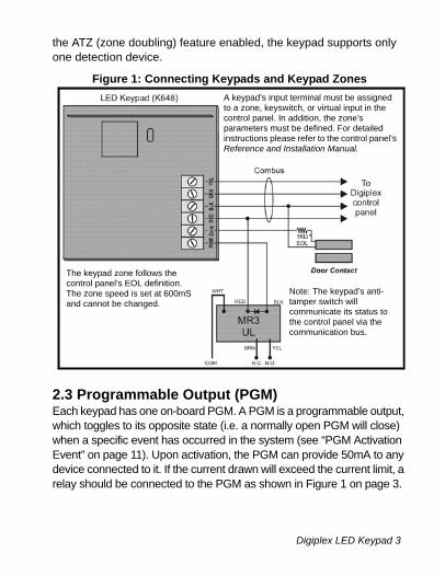
the ATZ (zone doubling) feature enabled, the keypad supports only one detection device.
Figure 1: Connecting Keypads and Keypad Zones
2.3 Programmable Output (PGM)Each keypad has one on-board PGM. A PGM is a programmable output, which toggles to its opposite state (i.e. a normally open PGM will close) when a specific event has occurred in the system (see “PGM Activation Event” on page 11). Upon activation, the PGM can provide 50mA to any device connected to it. If the current drawn will exceed the current limit, a relay should be connected to the PGM as shown in Figure 1 on page 3.
A keypad’s input terminal must be assigned to a zone, keyswitch, or virtual input in the control panel. In addition, the zone’s parameters must be defined. For detailed instructions please refer to the control panel’s Reference and Installation Manual.
The keypad zone follows the control panel’s EOL definition. The zone speed is set at 600mS and cannot be changed.
Note: The keypad’s anti-tamper switch will communicate its status to the control panel via the communication bus.
Digiplex LED Keypad 3n
3.0 ProgrammingProgram the LED keypad using any LCD keypad on the communication bus or using the Winload software. We strongly recommend you read this entire manual before you begin programming.
This model does not support installer programming capabilities, therefore you cannot program other modules or the panel on the communication bus using this unit.
3.1 Winload ProgrammingUsing the WinLoad Security System Management Software, you can program control panels and keypads remotely through a modem at 300 baud or on-site at 19.2k/38.4k baud with a 306 Adapter. For more information refer to the WinLoad OnLine Help.
4 Reference & Installation Manual

4.0 System Options
Figure 2: Keypad Overview
[ENTER] Saves current data and exits current menu.[CLEAR] Erases current data entry or reverts to the preceding step.
Partition Lights: (A1, A2, A3 and A4)ON = Partition armedOFF = Partition disarmedFLASH = Partition in alarm
Action Lights: (Access, Stay,Force, Mem, Trbl and Prg)Lights will illuminate accordingto the status of the system.
Numerical Lights: (Zones) ON = Open / breachedOFF = OKFLASHES = Tamper / fire loop
“AC” Light:ON = AC PowerOFF = Power failure
“Status” Light:
When green:ON = All zones closedOFF = Zone(s) openFLASH = Exit Delay in progress
When red:ON = All partitions armedOFF = Partition disarmedFLASH = Partition in alarm
Keypad will display the status of all its assigned partitions.
Digiplex LED Keypad 5n

4.1 Partition DisplaySection [001] to [008]
You can program the LED keypad to display up to four partitions. Sections [001] to [008] correspond to partitions 1 to 8. The LED numbers A1 to A4 are assigned values 001 to 004 (see section 3). To assign a display number to a partition, choose a section number from [001] to [008] and assign it a value between 001 and 004 which represents LED numbers A1 to A4 respectively.
Figure 3: LED Partition Display
Do not assign the same display number to more than one section. For example, you cannot assign value 002 to sections [003] and [004]. The rejection beep will remind you that a selected display number is already assigned to another section. Refer to section 6.0 on page 14 for default values.
Example:LED A3 is assigned to partition 3. To reassign LED A3 to partition 8 perform the following steps:1) Enter [003] to select partition 3.2) Enter [000] to clear the value.
Value: 001 002 003 004
6 Reference & Installation Manual
3) Enter [008] to select partition 8.4) Enter value [003] to reassign display number A3 to partition 8.5) Press the [CLEAR] key to exit.
4.2 Zone DisplaySection [101] To [196]
You can program the keypad to display any zone from 1 to 96 up to a total of 48. Sections [101] to [196] correspond to zones 1 to 96 respectively. These zones are displayed on LED numbers 1 to 48 and are assigned values 001 to 048.
Do not assign more than one LED number to a zone. For example, you cannot assign LED number 33 to zones 21 and 28. The rejection beep will remind you that a selected LED number is already assigned to another section. Refer to section 6.0 on page 14 for default values.
Example:LED number 29 is assigned to zone 29. To reassign LED number 29 to zone 47 perform the following steps:
1) Enter [129] to select system zone 29.2) Enter [000] to clear the value.3) Enter [147] to select system zone 47. 4) Enter value [029] to reassign LED number 29 to zone 47.5) Press the [CLEAR] key to exit.
Every time the [CLEAR] key is pressed it will revert to the preceding step, unless entering in data in which case it will erase the current entry.
4.3 Section Reset Section [040] This section resets zone display sections [101] to [196] to default settings. Enter [040] to perform the reset.
Digiplex LED Keypad 7n
4.4 Confidential ModeSection [009] Option [1]
The keypad will switch to Confidential Mode after a period of inactivity (default is 120 sec.) if option [1] is enabled. In Confidential Mode all LEDs will turn off until either a button is pressed or an access code is entered (see section 4.5). Once the keypad is activated, all applicable LEDs will illuminate. Refer to page 11 for Confidential Mode Timer.
Option [1] OFF = Disabled (default).Option [1] ON = Enabled.
4.5 Exit Confidential ModeSection [009] Option [2]
If confidential mode is enabled, option [2] determines how the keypad will return to normal mode after the keypad has switched to confidential mode (see section 4.4).
Option [2] ON = Exit Confidential Mode by entering an access code.Option [2] OFF = Exit Confidential Mode by pressing a button (default).
Option [2] must be set to ON on UL listed systems.Option [2] will only work if option [1] is enabled.
4.6 Confidential Mode TimerSection [012]
Section [012] determines the amount of time without action before the keypad enters Confidential Mode. For more information on Confidential Mode, refer to “Confidential Mode” on page 8. The Confidential Mode Timer can be set from 005 seconds to 255 seconds. Default: 120 seconds
8 Reference & Installation Manual
4.7 MutingSection [009] Option [3]
You can program the keypad not to emit audible sounds, including Chimed zones. During Muting, the keypad will only emit the Confirmation Beep, Rejection Beep and beep when users press a button.
Option [3] OFF = Audible sounds (default).Option [3] ON = Mute.
4.8 Beep on Exit DelaySection [009] Option [4]
The keypad can beep once every second during the Exit Delay Timer. During the final 10 seconds, it will beep more rapidly to provide a final warning before the partition is armed.
Option [4] OFF = Exit Delay beep disabled.Option [4] ON = Exit Delay beep enabled (default).
4.9 Chime on Zone ClosureSection [009] Option [5]
During the Chime Zone Time Period that the user sets, the keypad can emit an intermittent beep whenever a zone with the Chime feature enabled closes (see the user manual for details on Chime Zones). If the user does not set the Chime Zone time period and this option is enabled, the Chime Zones will always beep upon closure.
Option [5] OFF = Chime on Zone Closure disabled (default).Option [5] ON = Chime on Zone Closure enabled.
4.10 Beep on TroubleSection [010] Options [1] To [4]
Potential troubles are sorted into groups. With these options enabled,
Digiplex LED Keypad 9n

the keypad will emit an intermittent beep whenever a trouble condition from the Trouble Groups occurs in the system. The intermittent beep will remain activated until the user enters the Trouble Display or if the trouble is resolved (see your control panel’s Reference & Installation Manual for details concerning Trouble Display). The intermittent beep will reinitialize whenever the trouble reoccurs.
System Troubles / Clock LossOption [1] OFF = Disabled (default).Option [1] ON = Enabled.
Communicator TroublesOption [2] OFF = Disabled (default).Option [2] ON = Enabled.
Module / Communication Bus TroublesOption [3] OFF = Disabled (default).Option [3] ON = Enabled.
Zone TroublesOption [4] OFF = Disabled (default).Option [4] ON = Enabled.
4.11 Keypad Anti-tamper EnableSection [011] Option [5]
When the tamper option is enabled and the keypad's anti-tamper switch is triggered, the keypad will send a tamper report to the control panel via the communication bus. For information on how the control panel will process the tamper, refer to the tamper recognition options in your control panel’s Reference and Installation manual.
Option [5] OFF = Keypad's anti-tamper is disabled (default).Option [5] ON = Keypad's anti-tamper is enabled.
10 Reference & Installation Manual
5.0 PGM Programming
5.1 PGM StateSECTION [011] OPTION [1]
The keypad's on-board PGM can be set as normally open or normally closed. When an open PGM is activated, it will close the circuit to the ground and enable any devices connected to it. When a closed PGM is activated, it will open the circuit and disable any devices connected to it. When the PGM Activation Event occurs (see section 5.2), the PGM will switch to its opposite state (i.e. open to closed or closed to open). The PGM is limited to 50mA.
Option [5] OFF = PGM is Normally Open (default).Option [5] ON = PGM is Normally Closed.
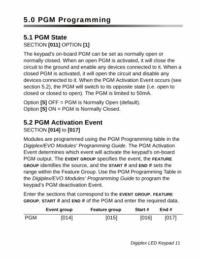
5.2 PGM Activation EventSECTION [014] to [017]
Modules are programmed using the PGM Programming table in the Digiplex/EVO Modules’ Programming Guide. The PGM Activation Event determines which event will activate the keypad's on-board PGM output. The EVENT GROUP specifies the event, the FEATURE GROUP identifies the source, and the START # and END # sets the range within the Feature Group. Use the PGM Programming Table in the Digiplex/EVO Modules’ Programming Guide to program the keypad’s PGM deactivation Event.
Enter the sections that correspond to the EVENT GROUP, FEATURE GROUP, START # and END # of the PGM and enter the required data.
Event group Feature group Start # End #
PGM [014] [015] [016] [017]
Digiplex LED Keypad 11n
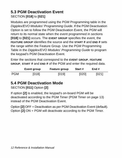
5.3 PGM Deactivation EventSECTION [018] to [021]
Modules are programmed using the PGM Programming table in the Digiplex/EVO Modules’ Programming Guide. If the PGM Deactivation Option is set to follow the PGM Deactivation Event, the PGM will return to its normal state when the event programmed in sections [018] to [021] occurs. The EVENT GROUP specifies the event, the FEATURE GROUP identifies the source and the START # and END # sets the range within the Feature Group. Use the PGM Programming Table in the Digiplex/EVO Modules’ Programming Guide to program the keypad’s PGM Deactivation Event.
Enter the sections that correspond to the EVENT GROUP, FEATURE GROUP, START # and END # of the PGM and enter the required data.
5.4 PGM Deactivation ModeSECTION [011] Option [2]
If option [2] is enabled, the keypad's on-board PGM will be deactivated according to the PGM Timer (PGM Timer on page 13) instead of the PGM Deactivation Event.
Option [2] OFF = Deactivation as per PGM Deactivation Event (default).Option [2] ON = PGM will deactivate according to the PGM Timer.
Event group Feature group Start # End #
PGM [018] [019] [020] [021]
12 Reference & Installation Manual
5.5 PGM Base TimeSECTION [011] Option [3]
This option defines whether the value programmed in section [013] is in minutes or seconds.
Option [3] OFF = PGM Base Time is 1 second (default).Option [3] ON = PGM Base Time is 1 minute.
5.6 PGM TimerSECTION [013]
If the PGM Deactivation Mode is set to follow the PGM timer, the value programmed in section [013] represents how long the PGM will remain in its opposite state (see “PGM State” on page 11) after being activated. To program the timer, enter a 3-digit decimal value (001 to 255) in section [013]. The 3-digit value will be multiplied by the PGM Base Time of 1 second or 1 minute (see section 5.5).
5.7 PGM TestSECTION [030]
Use this section to initiate a PGM test, which will activate the PGM for 8 seconds. Enter section [030] to activate this test.
Digiplex LED Keypad 13n
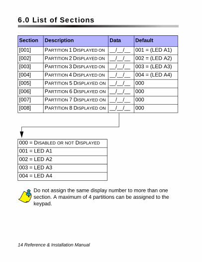
6.0 List of Sections
Do not assign the same display number to more than onesection. A maximum of 4 partitions can be assigned to the keypad.
Section Description Data Default
[001] PARTITION 1 DISPLAYED ON __/__/__ 001 = (LED A1)[002] PARTITION 2 DISPLAYED ON __/__/__ 002 = (LED A2)[003] PARTITION 3 DISPLAYED ON __/__/__ 003 = (LED A3)[004] PARTITION 4 DISPLAYED ON __/__/__ 004 = (LED A4)[005] PARTITION 5 DISPLAYED ON __/__/__ 000[006] PARTITION 6 DISPLAYED ON __/__/__ 000[007] PARTITION 7 DISPLAYED ON __/__/__ 000[008] PARTITION 8 DISPLAYED ON __/__/__ 000
000 = DISABLED OR NOT DISPLAYED
001 = LED A1 002 = LED A2003 = LED A3004 = LED A4
14 Reference & Installation Manual

= DefaultSECTION [009]: Keypad Options
Option Description OFF ON
[1] CONFIDENTIAL MODE DISABLED ENABLED
[2] EXIT CONFIDENTIAL MODE
PRESS KEY ENTER CODE
[3] MUTING DISABLED ENABLED
[4] BEEP ON EXIT DELAY DISABLED ENABLED
[5] CHIME ON ZONE CLOSURE
DISABLED ENABLED
[6] TO [8] N/A
Section [010]: Beep on Trouble
Option Description OFF ON
[1] BEEP ON SYSTEM TROUBLES / CLOCK LOSS
DISABLED ENABLED
[2] BEEP ON COMMUNICATOR TROUBLES
DISABLED ENABLED
[3] BEEP ON MODULE / BUS TROUBLES
DISABLED ENABLED
[4] BEEP ON ZONE TROUBLES DISABLED ENABLED
[5] TO [8] N/A
Digiplex LED Keypad 15n

= DefaultSection [011]: Keypad Tamper Enable
Option Description OFF ON
[1] PGM STATE N.O. N.C.
[2] PGM DEACTIVATION MODE
DEACTIVATION EVENT
PGM TIMER
[3] PGM BASE TIME 1 SECOND 1 MINUTE
[4] N/A
[5] KEYPAD ANTI-TAMPER DISABLED ENABLED
[6] TO [8] N/A
Section Data Description Default
[012] __/__/__ (005-255) CONFIDENTIAL MODE TIMER
120 SEC.
Section Data Description Default
[013] __/__/__ (001-255) PGM TIMER 005
16 Reference & Installation Manual
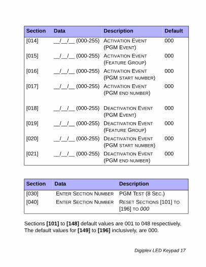
Sections [101] to [148] default values are 001 to 048 respectively. The default values for [149] to [196] inclusively, are 000.
Section Data Description Default
[014] __/__/__ (000-255) ACTIVATION EVENT(PGM EVENT)
000
[015] __/__/__ (000-255) ACTIVATION EVENT(FEATURE GROUP)
000
[016] __/__/__ (000-255) ACTIVATION EVENT (PGM START NUMBER)
000
[017] __/__/__ (000-255) ACTIVATION EVENT (PGM END NUMBER)
000
[018] __/__/__ (000-255) DEACTIVATION EVENT(PGM EVENT)
000
[019] __/__/__ (000-255) DEACTIVATION EVENT(FEATURE GROUP)
000
[020] __/__/__ (000-255) DEACTIVATION EVENT(PGM START NUMBER)
000
[021] __/__/__ (000-255) DEACTIVATION EVENT(PGM END NUMBER)
000
Section Data Description
[030] ENTER SECTION NUMBER PGM TEST (8 SEC.)[040] ENTER SECTION NUMBER RESET SECTIONS [101] TO
[196] TO 000
Digiplex LED Keypad 17n

Section LED Number
Zone Displayed Section LED
NumberZone Displayed
[101] __/__/__ ZONE 1 [115] __/__/__ ZONE 15[102] __/__/__ ZONE 2 [116] __/__/__ ZONE 16[103] __/__/__ ZONE 3 [117] __/__/__ ZONE 17[104] __/__/__ ZONE 4 [118] __/__/__ ZONE 18[105] __/__/__ ZONE 5 [119] __/__/__ ZONE 19[106] __/__/__ ZONE 6 [120] __/__/__ ZONE 20[107] __/__/__ ZONE 7 [121] __/__/__ ZONE 21[108] __/__/__ ZONE 8 [122] __/__/__ ZONE 22[109] __/__/__ ZONE 9 [123] __/__/__ ZONE 23[110] __/__/__ ZONE 10 [124] __/__/__ ZONE 24[111] __/__/__ ZONE 11 [125] __/__/__ ZONE 25[112] __/__/__ ZONE 12 [126] __/__/__ ZONE 26[113] __/__/__ ZONE 13 [127] __/__/__ ZONE 27[114] __/__/__ ZONE 14 [128] __/__/__ ZONE 28
18 Reference & Installation Manual
Section LED Number
Zone Displayed Section LED
NumberZone Displayed
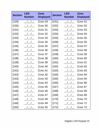
[129] __/__/__ ZONE 29 [151] __/__/__ ZONE 51[130] __/__/__ ZONE 30 [152] __/__/__ ZONE 52[131] __/__/__ ZONE 31 [153] __/__/__ ZONE 53[132] __/__/__ ZONE 32 [154] __/__/__ ZONE 54[133] __/__/__ ZONE 33 [155] __/__/__ ZONE 55[134] __/__/__ ZONE 34 [156] __/__/__ ZONE 56[135] __/__/__ ZONE 35 [157] __/__/__ ZONE 57[136] __/__/__ ZONE 36 [158] __/__/__ ZONE 58[137] __/__/__ ZONE 37 [159] __/__/__ ZONE 59[138] __/__/__ ZONE 38 [160] __/__/__ ZONE 60[139] __/__/__ ZONE 39 [161] __/__/__ ZONE 61[140] __/__/__ ZONE 40 [162] __/__/__ ZONE 62[141] __/__/__ ZONE 41 [163] __/__/__ ZONE 63[142] __/__/__ ZONE 42 [164] __/__/__ ZONE 64[143] __/__/__ ZONE 43 [165] __/__/__ ZONE 65[144] __/__/__ ZONE 44 [166] __/__/__ ZONE 66[145] __/__/__ ZONE 45 [167] __/__/__ ZONE 67[146] __/__/__ ZONE 46 [168] __/__/__ ZONE 68[147] __/__/__ ZONE 47 [169] __/__/__ ZONE 69[148] __/__/__ ZONE 48 [170] __/__/__ ZONE 70[149] __/__/__ ZONE 49 [171] __/__/__ ZONE 71[150] __/__/__ ZONE 50 [172] __/__/__ ZONE 72
Digiplex LED Keypad 19n

Do not assign the same zone number to more than one LED number. Zones can only be displayed on 48 LEDs.
Section LED Number
Zone Displayed Section LED
NumberZone Displayed
[173] __/__/__ ZONE 73 [186] __/__/__ ZONE 86[174] __/__/__ ZONE 74 [187] __/__/__ ZONE 87[175] __/__/__ ZONE 75 [188] __/__/__ ZONE 88[176] __/__/__ ZONE 76 [189] __/__/__ ZONE 89[177] __/__/__ ZONE 77 [190] __/__/__ ZONE 90[178] __/__/__ ZONE 78 [191] __/__/__ ZONE 91[179] __/__/__ ZONE 79 [192] __/__/__ ZONE 92[180] __/__/__ ZONE 80 [193] __/__/__ ZONE 93[181] __/__/__ ZONE 81 [194] __/__/__ ZONE 94[182] __/__/__ ZONE 82 [195] __/__/__ ZONE 95[183] __/__/__ ZONE 83 [196] __/__/__ ZONE 96[184] __/__/__ ZONE 84[185] __/__/__ ZONE 85
20 Reference & Installation Manual

Warranty
For complete warranty information on this product please refer to the Limited Warranty Statement found on the website www.paradox.com/terms. Your use of the Paradox product signifies your acceptance of all warranty terms and conditions.
© 2002-2007 Paradox Security Systems Ltd. All rights reserved. Specifications may change without prior notice. One or more of the following US patents may apply: 7046142, 6215399, 6111256, 6104319, 5920259, 5886632, 5721542, 5287111, 5119069, 5077549 and RE39406 and other pending patents may apply. Canadian and international patents may also apply.
Digiplex and Digiplex EVO are trademarks or registered trademarks of Paradox Security Systems Ltd. or its affiliates in Canada, the United States and/or other countries. For the latest information on products approvals, such as UL and CE, please visit www.paradox.com.

Notes


For technical support in Canada or the U.S., call 1-800-791-1919, Monday to Friday from 8:00 a.m. to 8:00 p.m. EST.
For technical support outside Canada and the U.S., call 00-1-450-491-7444, Monday to Friday from 8:00 a.m. to 8:00 p.m. EST.
Please feel free to visit our website at www.paradox.com.
PRINTED IN CANADA 1/2009 paradox.com K648-EI10