4ft sma-wk-4 wind kit 250 kmh (nmt207-07)
TRANSCRIPT

NMT 207-07(e)
It is important to mount the antenna exactly as described in this addendum.The installed antenna shall be inspected once per year by qualifi ed personnel.
RFS disclaims any responsibility for the result of improper or unsafe installation.This installation instruction has been written for qualifi ed, skilled personnel.
We reserve the right to alter details, especially with respect to technical improvement.
Sales department : Radio Frequency Systems GmbHKabelkamp 20, D-30179 Hannover (Germany) - Tel. +49-511 676-25 20 - Fax +49-511 676-25 21
Plant : RFS France Trignac - Fax +33 02 40 90 41 43 1/3
1. Description
All 4 ft antennas provided with STD or T-Mount withstand a survival windspeed of 200 Km/h. These antennas can be equipped with the SMA-WK-4 WindKit, to increase their survival wind speed to
250 Km/h. (This kit does not be use with 4 ft antennas provided with E-Mount)
These 250 km/h WindKit is composed of :
- 1 sway bar Ø 33 mm x 1.5 m - 1 hardware pack
2. Tool required for installation
- Wrenches for hexagon bolts or nuts HM6 (10 mm), HM8 (13 mm), HM10 (17 mm) - Torque wrench (up to 35 Nm)
3. Assembly of the sway bar
The sway bar must be fi xed between the antenna and the tower, af-ter azimuth and elevation adjustment. The sway bar is always fi xed opposite to the pipe support.
For an antenna with a shroud, the sway bar clamp must be installed on the refl ector before the installation of the radome.
This installation instruction shows the process for an antennas with an offset left, for an offset right, the sway bar is inver-ted.
Addendum
Microwave Parabolic 4 ft Antennas 250 km/h WindKitKit : SMA-WK-4 (for Ant. Equipped with STD or T-Mount)
Antenna without shroudequipped with kit SMA-WK-4
Antenna with shroudequipped with kit SMA-WK-4
Sway bar clamp

2/3NMT 207-07(e)
Sl nut M10Washer 10.5
Washer 10.5 Ø30Screw M10x35
Sway barterminal Sway bar
Ø 33 x 1.5 m
2 U-bolts M6/334 washers 6.4
8 nuts M6
Fixing plate sway bar 33 2 screws M8x25 2 washers 8.4 Ø24
Washers 10.5Sl nuts M10
Screws M10x30
Fixing clamp sway bar(L-Profi l 60x60)
Screw M10x70Washer 10.5Sl nut M10
to tower structure*
2 washers 8.4 Ø242 sl nuts M8
Sway bar clamp 33(L-Profi l 40x40)
This part must installedbefore radome installation
* This windkit is provided for a sway bar attachment on a tower with an angle profi l structure.For an attachment of the sway bar on a tower with a pipe structure Ø48 up to 114 mm, you need to add the «sway bar Ø33 / tower kit option» Kit: SMA-SKO-48-114.
Sl nut M10Washer 10.5
Washer 10.5 Ø30Screw M10x35
Sway barterminal
Sway barØ 33 x 1.5 m
2 U-bolts M6/334 washers 6.4
8 nuts M6
Fixing plate sway bar 33
Washers 10.5Sl nuts M10
Screws M10x30
Fixing clamp sway bar(L-Profi l 60x60)
Screw M10x70Washer 10.5
Sl nut M10
to tower structure*
For antennawith shroud
For antennawithout shroud
3/3NMT 207-07(e)
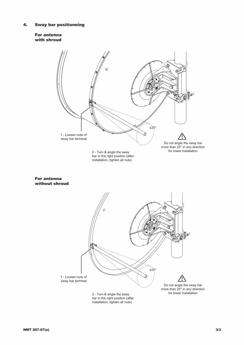
4. Sway bar positionning
±25°
1 - Loosen nuts ofsway bar terminal
2 - Turn & angle the sway bar in the right position (after installation, tighten all nuts)
Do not angle the sway bar more than 25° in any direction
for tower installation
For antennawith shroud
For antennawithout shroud
±25°
1 - Loosen nuts ofsway bar terminal
2 - Turn & angle the sway bar in the right position (after installation, tighten all nuts)
Do not angle the sway bar more than 25° in any direction
for tower installation