5 ave solnvidyalankar.org/file/diploma/prelim_paper_soln/semv/etrx/...prelim question paper solution...
TRANSCRIPT

1013/TY/Pre_Pap/Elec/AVE_Soln 113
Vidyalankar T.Y. Diploma : Sem. V [EN/EX/EJ/DE/ED/EI]
Audio Video Engineering Prelim Question Paper Solution
(i) Hi-Fi Stereo Reproducing System Fig.1 shows the block diagram of a high fidelity stereo reproducing system. High fidelity sound can be obtained from the recorded stereo tape or in
live system from the microphones. (Stereo signal can also be obtained from record player).
The stereo signal is fed to two independent amplification channels through tape-mic switch. The amplifier system consists of low noise high gain pre-amplifier, equaliser, well designed amplifiers giving flat frequency response and little distortion by using negative feedback circuit and then the matching transformer.
(A balancing circuit is incorporated to balance out any imbalance in the characteristics of otherwise identical circuits). The secondary of the matching transformer of each channel is connected to the respective loudspeaker column. For Hi-Fi, the loudspeaker columns consist of woofer, squawker and tweeter.
All the blocks are designed so as to get flat frequency response (from 40 to 15000 Hz), little distortion (less than 1%), high signal to noise ration (more than 50 dB) and high dynamic range (100 dB) to achieve the final output of high fidelity.
Fig. 1 : Block diagram of Hi-Fi reproducing system
1. (a)
Vidyala
nkar

Vidyalankar : T.Y. Diploma AVE
1013/TY/Pre_Pap/Elec/AVE_Soln 114
(ii) Advantages & Disadvantages of Compact Discs Advantages i) As it is covered by transparent plastic or transparent lacquer, the tracks
and recording remain safe and are not affected by dust, grease and scratches. CD is immune to the surface contamination.
ii) Signal to noise ratio is high. iii) Dynamic range is high. iv) Channel separation is high. v) Wow does not exist. vi) Flutter does not exist. vii) Total distortion is low. viii) Frequency response is excellent and covers complete audio range. ix) Size is quite small.
Disadvantages The cost of CD is more than the Hi-Fi conventional (analog) disc.
(iii) Back Porch Time duration of 5.8 S between end of sync pulses and starting of picture
information. This is provided to : i) Avoid the light and dark strips at left of raster. If back porch is not provided, due to sudden change in direction of
current through deflection coil, oscillations in deflection coil will produce light and dark strips at left of raster.
ii) Used as reference d.c. level while doing DC reinsertion. D.C. reinsertion is required when the video signal is passed to A.C. amplifier RC [coupling cap] because the capacitor blocks the dc signal which indicated the average brightness level of one picture.
iii) It also permits time for horizontal time base circuit to reverse direction of current for the initiation of the scanning of next line.
iv) The necessary amplitude equal to the blanking level and enables to preserve the dc content of the picture information at the transmitter.
v) At the receiver, this level which is independent of the picture details is utilized in AGC [automatic gain control] circuit to develop true AGC voltage proportional to the signal strength picked up at the antenna.
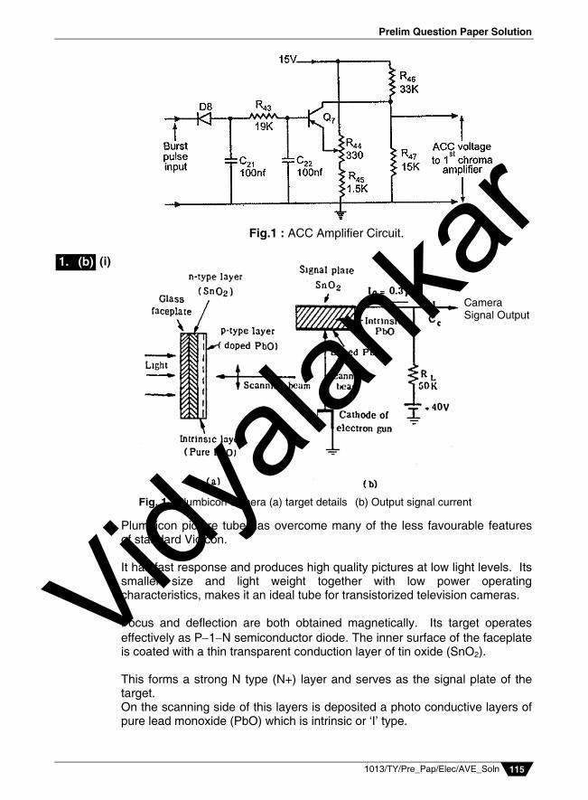
(iv) Automatic Colour Correction (ACC) Amplifier
Burst pulse is fed to ACC amplifier diode D8 and R43, C21 and C22 forms half wave rectifier and filter circuit.
It provides negative d.c. voltage which is proportional to amplitude of received signal.
Output of Q7 is positive voltage which changes with amplitude of chroma signal.
This voltage is normally 7 V. It is given to 1st chroma amplifier to control its gain. Purpose of R46 and
R47 is to obtain correct steady bias for the 1st chroma amp. R44 provides adjustable reverse bias for Q7 to delay conduction until the
chroma signal exceeds a given threshold.
1. (a)
1. (a)
1. (a)
Vidyala
nkar
Prelim Question Paper Solution
1013/TY/Pre_Pap/Elec/AVE_Soln 115
Fig.1 : ACC Amplifier Circuit.
(i)
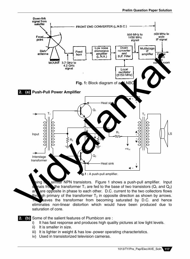
Plumbicon picture tube has overcome many of the less favourable features of standard Vidicon. It has fast response and produces high quality pictures at low light levels. Its smaller size and light weight together with low power operating characteristics, makes it an ideal tube for transistorized television cameras. Focus and deflection are both obtained magnetically. Its target operates effectively as P1N semiconductor diode. The inner surface of the faceplate is coated with a thin transparent conduction layer of tin oxide (SnO2). This forms a strong N type (N+) layer and serves as the signal plate of the target. On the scanning side of this layers is deposited a photo conductive layers of pure lead monoxide (PbO) which is intrinsic or ‘I’ type.
Fig. 1 : Plumbicon camera (a) target details (b) Output signal current
Camera Signal Output
1. (b)
Vidyala
nkar

Vidyalankar : T.Y. Diploma AVE
1013/TY/Pre_Pap/Elec/AVE_Soln 116
Finally PbO is doped to form a P type semiconductor on which the scanning beam lands. The details of the target are shown in Fig.1(a). The overall thickness of the target is 15 106 m Fig.1(b) shows necessary circuit details for developing the video signal. In the standard Vidicon each element acts as a leaky capacitor, with the leakage resistance decreasing with increasing light intensity. In the plumbicon, however, each element serves as a capacitor in series with a reverse biased light controlled diode. Light from the scene being televised is focussed through the transparent layer of tinoxide on to the photo conductive lead monoxide. Without light the target prevents any conduction because of absence of any charge carriers and so there is little or no output current. A typical value of Dark current is around 4nA. The incident light on the target results in photo excitation of semiconductor junction between the pure PbO and doped layer. The resultant decrease in resistance causes signal current flow which is proportional to the incident light on each photo element. The overall thickness of the target is 10 to 20 m.
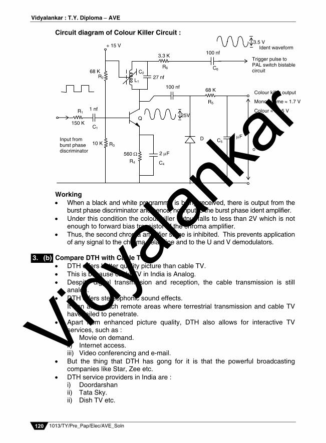
(ii) LNBC The main function of the LNBC is to convert collected signal to a low frequency range to minimize losses in co-axial cable that carry dish antenna signals to control room. The figure 1 shows block diagram of LNBC or also called front end converter. The composite signal collected by the feed horn is fed to a Low Noise
Amplifier (LNA) which provides enough gain while maintaining maximum possible signal-to-noise ratio.
The LNA output fed to a converter which converts the incoming microwave (high frequency) signals to a lower frequency range.
This is done using local oscillator frequency of converter. A Band Pass Filter (BPF) at the output of mixer separates the wanted
I.F. signals from other signals. These signals are amplified by multistage I.F. amplifier and then sent to
co-axial cable to the control room (or cable station). It is necessary to install 2, 4, 6 or 8 dish antenna units with feed-horn and
LNBC to collect signals from different satellites.
1. (b)
Vidyala
nkar
Prelim Question Paper Solution
1013/TY/Pre_Pap/Elec/AVE_Soln 117
Fig. 1: Block diagram of an LNBC.
Push-Pull Power Amplifier
Using two similar NPN transistors. Figure 1 shows a push-pull amplifier. Input signals from the transformer T1 are fed to the base of two transistors (Q1 and Q2) and are opposite in phase to each other. D.C. current to the two collectors flows through primary of the transformer T2 in opposite direction as shown by arrows. This saves the transformer from becoming saturated by D.C. and hence eliminates non-linear distortion which would have been produced due to saturation of core.
Some of the salient features of Plumbicon are : i) It has fast response and produces high quality pictures at low light levels. ii) It is smaller in size. iii) It is lighter in weight & has lowpower operating characteristics. iv) Used in transistorized television cameras.
LS
T2
+vcc
Heat sink
Heat sink
R1
Re R2
Q1
Q2
T1
Input
Interstage transformer
Fig.1 : A push-pull amplifier.
2. (a)
2. (b)
Vidyala
nkar

Vidyalankar : T.Y. Diploma AVE
1013/TY/Pre_Pap/Elec/AVE_Soln 118
v) The overall thickness of the target is 15 106 M vi) It has higher sensitivity due to much reduced recombination of
photogenerated electrons and holes in the intrinsic layer which contains very few discontinuities.
Merits and Demerits of SECAM Systems –
Merits i) Because of FM, SECAM receivers are immune to phase distortion. ii) No possibility of cross-talk between the colour difference signals. iii) No need for the use of Q.A.M. at the transmitter and synchronous detectors
at the receiver. iv) The subcarrier enjoys all the advantages of FM. v) The receiver does not need ATC and ACC circuits. vi) A separate manual saturation control and a hue control are not necessary. All this makes the SECAM receiver simple and cheaper compared to NTSC
and PAL receiver.
Demerit When a composite signal involving luminance and chrominance is faded out
in studio operation, if the luminance signal that is readily attenuated and not the chrominance. This makes the colour more saturated during fade to black. Thus, a pink colour will change to red during fade-out. This is not the case in NTSC or PAL systems.
The width of vertical sync pulse have to be larger than horizontal sync pulse because: i) In order to derive a suitable field sync pulse at the receiver to trigger the field
sweep oscillator. ii) The standards specify that the vertical sync period should be 2.5 to 3 times
the horizontal line period. iii) If the width is less than this, it becomes difficult to distinguish between
horizontal and vertical pulses at the receiver. iv) If width is greater than this, the transmitter must operate at peak power for an
unnecessarily long interval of time.
DTH System
Fig. 1 : DTH Block Diagram.
2. (c)
2. (d)
2. (e)
Vidyala
nkar

Prelim Question Paper Solution
1013/TY/Pre_Pap/Elec/AVE_Soln 119
A DTH network consists of a broadcasting centre satellites, encoders, multiplexers, modulators and DTH receivers.
A DTH service provider has to lease Ku-band transponders from' satellite. The Encoder converts the audio, video and data signals into the digital
format and the multiplexer mixes these signals. At the user end, there will be a small dish antenna and set-top box to decode
and view numerous channels. On the user's end, receiving dishes can be as small as 45 cm in diameter. DTH is an encrypted transmission that travels to the consumer directly
through a satellite. DTH transmission is received directly by the consumer at his end through the
small dish antenna. A set-top box, unlike the regular cable connection, decodes the encrypted
transmission.
Purpose of Colour Killer Circuit The purpose of colour killer circuit is to make the chrominance bandpass
amplifier inoperative when the receiver is tuned to receive a black and white programme.
It thus prevents any illuminance signal which happens to fall within the
bandwidth of chrominance amplifier from getting through to the demodulators.
The passage of such random signals, on demodulation and amplification by
colour difference amplifers, causes annoying colour interference on the reproduced picture.
Thus, in effect the colour killer circuit act as electronic switch in the path of
chroma signal. It closes during reception of colour transmission and opens for monochrome programme.
The colour killer circuit is actuated by another circuit block (7.8 KHz tuned
amplifier), the operation of which depend on the presence or absence of colour burst.
3. (a)
Vidyala
nkar
Vidyalankar : T.Y. Diploma AVE
1013/TY/Pre_Pap/Elec/AVE_Soln 120
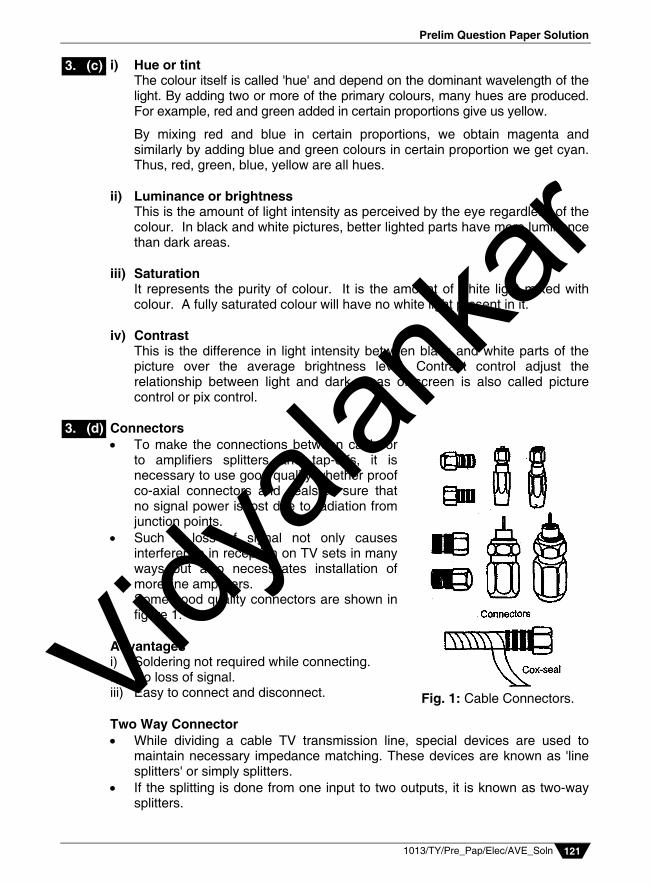
Circuit diagram of Colour Killer Circuit :
Working When a black and white programme is being received, there is output from the
burst phase discriminator and hence, no input to the burst phase ident amplifier. Under this condition the colour killer output falls to less than 2V which is not
enough to forward bias transistor of the chroma amplifier. Thus, the second chroma amplifier stage is inhibited. This prevents application
of any signal to the chroma delay line and to the U and V demodulators. Compare DTH with Cable TV DTH offers better quality picture than cable TV. This is because cable TV in India is Analog. Despite digital transmission and reception, the cable transmission is still
analog. DTH offers stereophonic sound effects. It can also reach remote areas where terrestrial transmission and cable TV
have failed to penetrate. Apart from enhanced picture quality, DTH also allows for interactive TV
services, such as : i) Movie on demand. ii) Internet access. iii) Video conferencing and e-mail. But the thing that DTH has gong for it is that the powerful broadcasting
companies like Star, Zee etc. DTH service providers in India are : i) Doordarshan ii) Tata Sky. ii) Dish TV etc.
+ 15 V
68 K R2
3.3 K 100 nf
R6 C6 C2
27 nf
100 nf
R1
150 K
1 nf
C1
R3 10 K
560
R4
2 F
C4
D 2 F
C5
R5
68 K
L1
Input from burst phase discriminator
Colour killer output
Monochrome 1.7 V
Colour 13.5 V
To
Trigger pulse to PAL switch bistable circuit
3.5 V Ident waveform
25V Q
3. (b)
Vidyala
nkar
Prelim Question Paper Solution
1013/TY/Pre_Pap/Elec/AVE_Soln 121
i) Hue or tint The colour itself is called 'hue' and depend on the dominant wavelength of the
light. By adding two or more of the primary colours, many hues are produced. For example, red and green added in certain proportions give us yellow.
By mixing red and blue in certain proportions, we obtain magenta and similarly by adding blue and green colours in certain proportion we get cyan. Thus, red, green, blue, yellow are all hues.
ii) Luminance or brightness This is the amount of light intensity as perceived by the eye regardless of the
colour. In black and white pictures, better lighted parts have more luminance than dark areas.
iii) Saturation It represents the purity of colour. It is the amount of white light mixed with
colour. A fully saturated colour will have no white light present in it. iv) Contrast This is the difference in light intensity between black and white parts of the
picture over the average brightness level. Contrast control adjust the relationship between light and dark areas of screen is also called picture control or pix control.
Connectors
To make the connections between cable or to amplifiers splitters and tap-offs, it is necessary to use good quality whether proof co-axial connectors and seals to sure that no signal power is lost due to radiation from junction points.
Such a loss of signal not only causes interference in reception on TV sets in many ways but also necessitates installation of more line amplifiers.
Some good quality connectors are shown in figure 1.
Advantages i) Soldering not required while connecting. ii) No loss of signal. iii) Easy to connect and disconnect. Two Way Connector While dividing a cable TV transmission line, special devices are used to
maintain necessary impedance matching. These devices are known as 'line splitters' or simply splitters.
If the splitting is done from one input to two outputs, it is known as two-way splitters.
Fig. 1: Cable Connectors.
3. (c)
3. (d)
Vidyala
nkar
Vidyalankar : T.Y. Diploma AVE
1013/TY/Pre_Pap/Elec/AVE_Soln 122
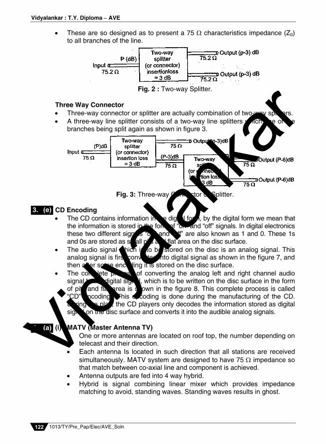
These are so designed as to present a 75 characteristics impedance (Z0) to all branches of the line.
Fig. 2 : Two-way Splitter.
Three Way Connector Three-way connector or splitter are actually combination of two-way splitters. A three-way line splitter consists of a two-way line splitters which one of the
branches being split again as shown in figure 3.
Fig. 3: Three-way Connector or Splitter.
CD Encoding
The CD contains information in the digital form, by the digital form we mean that the information is stored in the form of “on” and “off” signals. In digital electronics these two different signals “on” and “off” are also known as 1 and 0. These 1s and 0s are stored as small pits and flat area on the disc surface.
The audio signal which is to be stored on the disc is an analog signal. This analog signal is first converted into digital signal as shown in the figure 7, and then after some encoding it is stored on the disc surface.
The complete process of converting the analog left and right channel audio signal to the digital signal, which is to be written on the disc surface in the form of pits and flat area is shown in the figure 8. This complete process is called “CD” encoding”. This encoding is done during the manufacturing of the CD. During the play, the CD players only decodes the information stored as digital signal on the disc surface and converts it into the audible analog signals.
(i) MATV (Master Antenna TV)
One or more antennas are located on roof top, the number depending on telecast and their direction.
Each antenna Is located in such direction that all stations are received simultaneously. MATV system are designed to have 75 impedance so that match between co-axial line and component is achieved.
Antenna outputs are fed into 4 way hybrid. Hybrid is signal combining linear mixer which provides impedance
matching to avoid, standing waves. Standing waves results in ghost.
3. (e)
4. (a) Vidyala
nkar

Prelim Question Paper Solution
1013/TY/Pre_Pap/Elec/AVE_Soln 123
Fig. 1
The output from hybrid is fed to distribution amplifier by preamplifier. Function of these amplifier is to raise signal to level sufficient to prevent losses of distribution system.
The output from distribution amplifier is fed to splitters through co-axial line.
Co-axial distribution lines carry TV signals from the output of splitters to point of delivery called subcarrier tap-off.
These are either transformer coupled or capacitive coupled. They provide isolation between receivers thus prevent mutual
interference. Block Diagram (ii) Compact Disc Structure
The information is stored on the CD surface in the form of number of small pits in circular tracks. As shown in the figure 5, these pits have a depth of around 0.1 m and width of around 0.5 m.
The distance between each spiral track is around 1.6 m. This distance is known as “track pitch”. The distance between centerline of one track and the centerline of adjoining track is around 2.0 m and this distance is known as “pit spacing”.
4. (a) Vidyala
nkar

Vidyalankar : T.Y. Diploma AVE
1013/TY/Pre_Pap/Elec/AVE_Soln 124
If you want to imagine the smallness of these values, then, a human hair can contain about 30 tracks of the CD and the total length of the tracks on a CD can be as long as 2 to 3 miles. Also, if you increase the size of the pit on the disc surface to the size of a grain of rice, then, the diameter of the CD will increase to around half a mile. A typical CD consist of reflective surface coated with aluminum layer.
This reflective surface is covered with transparent plastic or lacquer coating. This coating acts as a protective layer for the reflective aluminum surface. Because of this protective coating, even if the disc becomes dirty one can clean it with the soap water and use the disc without any problem.
If there is some permanent damage such as a deep scratch on the surface of the disc, which will block the laser beam from reaching the reflective surface of the disc, then only the CD player will not be able to read the information stored at that area of the disc.
(iii) Considerations for designing cross-over networks
i) The cross-over frequency for woofer tweeter circuit is where the woofer output curve crosses the tweeter output curve. This is normally 1000 Hz. Hence, woofer gives output between 16-1000 Hz and tweeter from 1000 20000 Hz for 2 speaker system.
ii) Attenuation beyond the cut-off frequency for woofer and before the cut off frequency for tweeter should preferably be 12 dB per octave3 although 6 dB per octave is acceptable for economy models.
iii) For a three way speaker system, frequency coverage to the crossover point is as given below:
Woofer : 16 Hz to 500 Hz Squawker : 500 Hz to 5000 Hz Tweeter : 5000 Hz to 2000 Hz While for two way speaker system, it is as follows : Woofer : 16 Hz to 1000 Hz Tweeter : 1000 Hz to 20000 Hz iv) Inductors and capacitances should be calculated correctly. v) Electrolytic capacitors cannot be used as there is no polarization D.C.
current.
(i) RGB Drive Amplifiers Figure 1 shows the typical RGB video amplifier circuit with associated picture tube circuitary. It consists of three identical video amplifiers for driving the three cathodes
of picture tube. The inputs of amplifiers obtained from the decoded red, green and blue
outputs of chroma IC.
4. (a)
4. (b) Vidyala
nkar

Prelim Question Paper Solution
1013/TY/Pre_Pap/Elec/AVE_Soln 125
Fig. 1: RGB Drive Amplifier
Q1, Q2, Q3 are high frequency transistor of type BF393 or BF 869. The three amplifiers are of same design so their frequency response is
nearly same. Three amplifiers are identical so only one is considered to explain. Q1 of green signal amplifier is connected in CE configuration. 150 V dc supply is filtered by L2 and C9. C7 and C8 are bypass to the emitter supply. R15 and R12 provide negative feedback to improve d.c. stability. L3 in the collector load used to extend bandwidth. C1 at input to amplifier is to improve step response. The d.c. collector voltage, determines the picture tube cut-off voltage is
fixed by R17. R1 is varied for monochrome reproduction at high lights.
(ii) Generation of EHT for Picture Tubes In monochrome TV receiver EHT potential generating by overwind on L.O.T. but it is not possible beyond 16 kV because of problems like flash over, high impedance and poor regulation. So in colour TV to generate EHT upto 25 kV the diode split addition technique is used. It has advantages like greater reliability, small size and low cost.
4. (b) Vidyala
nkar

Vidyalankar : T.Y. Diploma AVE
1013/TY/Pre_Pap/Elec/AVE_Soln 126
Fig. 1 : Principle of Split Diode Operation to obtain EHT and Focus Anode Potentials for a Colour Picture Tube.
Figure 1 shows the principle of Diode split addition. Three layers of secondary windings are wound on ferroxide core of the
L.O.T (Line Output Transformers). In actual practice, three sections shown separately and wound one above
the other and are thus concentric. Each winding is identical to the other and has the same number of turns
therefore same voltage induced in each section. Every time the flyback-derived input pulse gets applied to the primary
winding (not shown here). The layers are close to each other, thus inter-layer capacitance exists
between each of them (shown by dotted line). If a diode is connected between the end of one layer of winding and the
start of next, the a.c. voltages induced in each layer can be made to charge up all the inter-layer capacitance to the same voltage.
Since the capacitances are effectively in series, the total voltage appearing at the output terminal is sum of all the voltages appearing across all of them.
The three windings are so designed that voltage induced in each layer form the flyback transformer 8.33 kV. This makes total potential equal to 25 kV and forms the EHT supply source.
Anode of 37 cm (14") monochrome picture tube needs 12 kV for good brightness on screen. 51 cm (20") B/W picture tube needs 16 kV.
Vidyala
nkar

Prelim Question Paper Solution
1013/TY/Pre_Pap/Elec/AVE_Soln 127
Fig. 2 : Production of video signal by Photoconduction
Fig. 1 : Production of video signal by photoemission
Photoemissive coating
The two photo electric effects used for converting variations of light into electrical variations are : i) Photo emission and ii) Photo conductivity In camera tubes employing photoconductive cathodes the scanning electron beam causes a flow of current through the photoconductive material. The amplitude of this current varies in accordance with the resistance offered by the surface at different points. Since the conductivity of the material varies in accordance with the light falling on it, the magnitude of the current represents the brightness variations of the scene.
This varying current completes its path under the influence of an applied dc voltage through a load resistance connected in series with path of the current.
5. (a)
Vidyala
nkar

Vidyalankar : T.Y. Diploma AVE
1013/TY/Pre_Pap/Elec/AVE_Soln 128
The instantaneous voltage developed across the load resistance is the video signal which after due to amplification and processing is amplitude modulated and transmitted. Figure 2 shows a simplified illustration of this method of developing video signal.
dB Meter Principle : The logarithmic term is applied to an electronic voltmeter when the current or voltage produced in the indicating instrument by an applied voltage is proportional to the logarithm of applied voltage. Such a characteristics leads to a linear decibel scale for the indicating
instruments and finds many applications in electronics. The reading on the meter scale is calibrated in decibels and hence the
instrument is called a dB voltmeter or simply dB meter. Block Diagram and Working Principle of dB Block Diagram :
Fig. 1 : Block Diagram of dB Meter.
Working: The RF signal to be measured is connected to the input of high impedance
input circuit through a RF connector, whose input impedance is 75 . The range selector switch selects the band and range of its frequencies to be
tuned. The logarithmic amplifier is connected to the differential amplified whose
signal output deflects the dB scale in the dB meter. To obtain logarithmic characteristics, the meter use a diode in feedback loop
of an op-amp. Features of the PAL System i) The weighted (B-Y) and (R-Y) signals are modulated without being given a
phase shift of 33° as is done in the NTSC system. ii) On modulation both the colour difference quadrature signals are allowed the
same bandwidth of about 1.3 MHz. This results in better colour reproduction. iii) The colour subcarrier frequency is chosen to be 4.43361875 MHz. This
results in somewhat better cancellation of the dot pattern interference, iv) The weighted (B-Y) and (R-Y) signals are modulated with the sub-carrier in
the same way as in NTSC system (9AM) but with the difference, that phase of the subcarrier to one of the modulators (V modulator) is reversed from +90° to -90° at the line of frequency. The name, phase alteration by line (i.e. PAL) is given from this mode of modulation.
This technique of modulation cancels hue errors which results from unequal phase shifts in the transmitted signal.
5. (b)
5. (c)
Vidyala
nkar
Prelim Question Paper Solution
1013/TY/Pre_Pap/Elec/AVE_Soln 129
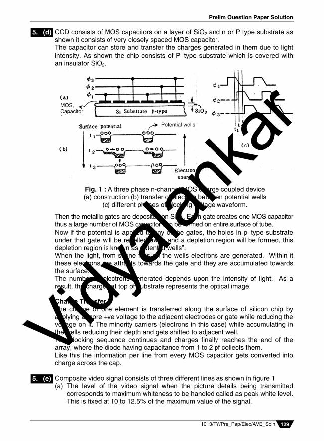
CCD consists of MOS capacitors on a layer of SiO2 and n or P type substrate as shown it consists of very closely spaced MOS capacitor. The capacitor can store and transfer the charges generated in them due to light intensity. As shown the chip consists of Ptype substrate which is covered with an insulator SiO2.
Then the metallic gates are deposited on SiO2. Each gate creates one MOS capacitor thus a large number of MOS capacitor can be formed on entire surface of tube. Now if the potential is applied to any of the gates, the holes in ptype substrate under that gate will be repelled away and a depletion region will be formed, this depletion region is known as potential wells”. When the light, from scene falls on the wells electrons are generated. Within it these electrons are attracts towards the gate and they are accumulated towards the surface. The number of electrons generated depends upon the intensity of light. As a result, the charges at top of substrate represents the optical image. Charge Transfer The charge of one element is transferred along the surface of silicon chip by applying a more +ve voltage to the adjacent electrodes or gate while reducing the voltage on it. The minority carriers (electrons in this case) while accumulating in the wells reducing their depth and gets shifted to adjacent well. This docking sequence continues and charges finally reaches the end of the array, where the diode having capacitance from 1 to 2 pf collects them. Like this the information per line from every MOS capacitor gets converted into charge across the cap. Composite video signal consists of three different lines as shown in figure 1 (a) The level of the video signal when the picture details being transmitted
corresponds to maximum whiteness to be handled called as peak white level. This is fixed at 10 to 12.5% of the maximum value of the signal.
5. (d)
5. (e)
Fig. 1 : A three phase n-channel MOS charge coupled device (a) construction (b) transfer of electron between potential wells
(c) different phases of clocking voltage waveform.
Potential wells
MOS, Capacitor
Vidyala
nkar

Vidyalankar : T.Y. Diploma AVE
1013/TY/Pre_Pap/Elec/AVE_Soln 130
Fig. 1 : Arbitrary picture signal details of three scanning lines with differentaverage brightness levels. Note that picture to sync ratio P/S = 10/4.
(b) The black level corresponds to approximately 72%. (c) The synch pulses are added at 75% level called the blanking level. (d) The region between black level and blanking level is called as ‘pedestal’. (e) However they merge and appears to be one practically so the picture
information vary between 10% to 75% of the CVs. (f) The darker the picture the higher will be the voltage within those limits.
Boosting in done in 4 bands : i) below 80 Hz ii) 80 Hz to 2999 Hz
iii) 3000 Hz and above iv) 9000 Hz and above Bands III and IV overlap above 9 kHZ, so that the high frequency noise
(hissing sound) is substantially reduced. Each band is processed separately by using low pass, band pass and high pass filters and limiters.
The 16 Hz to 80 Hz signal goes start which causes improvement in signal to noise ratio with respect to hum and rumble. 80 Hz to 2999 Hz signal goes to a band pass filter which deals with the mid-band noise. Most of the sound energy for music is concentrated in this band.
The 3000 Hz and 9000 Hz high pass filters improve signal to noise ratio with respect to hiss and modulation noise. The output of the four separate units is added. All this is done in a side branch, and this branch is known as differential network.
Interlace Scanning If 25 frames are scanned in 1 sec, we are able to see continuous picture on the screen. But in sequential scanning they are not rapid enough to allow the brightness of one picture or frame to blend smoothly into the next through the
6. (a)
6. (b)
Vidyala
nkar
Prelim Question Paper Solution
1013/TY/Pre_Pap/Elec/AVE_Soln 131
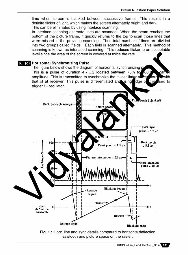
Fig. 1 : Horz. line and sync details compared to horizonta deflection sawtooth and picture space on the raster.
time when screen is blanked between successive frames. This results in a definite flicker of light, which makes the screen alternately bright and dark. This can be eliminated by using interlace scanning. In Interlace scanning alternate lines are scanned. When the beam reaches the bottom of the picture frame, it quickly returns to the top to scan those lines that were missed in the previous scanning. Thus total number of lines are divided into two groups called ‘fields’. Each field is scanned alternately. This method of scanning is known as interlaced scanning. This reduces flicker to an acceptable level since the area of the screen is covered at twice the rate.
Horizontal Synchronizing Pulse The figure below shows the diagram of horizontal synchronizing pulse.
This is a pulse of duration 4.7 S located between 75% to 100% of carrier amplitude. This is transmitted to synchronize the Hoscillator at transformer with that of at receiver. This pulse is differentiated and rising edge of it is used to trigger Hoscillator.
6. (c)
Vidyala
nkar
Vidyalankar : T.Y. Diploma AVE
1013/TY/Pre_Pap/Elec/AVE_Soln 132
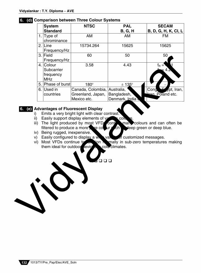
Comparison between Three Colour Systems
System Standard
NTSC PAL B, G, H
SECAM B, D, G, H, K, CI, L
1. Type of chrominance
AM AM FM
2. Line Frequency/Hz
15734.264 15625 15625
3. Field Frequency/Hz
60 50 50
4. Colour Subcarrier frequency MHz
3.58 4.43 fR = 4.41 fB = 4.25
5. Phase of burst 180 135 6. Used in
countries Canada, Colombia, Greenland, Japan, Mexico etc.
Australia, Bangladesh, Denmark, India etc.
Congo, Egypt, Iran, Iraq, Poland etc.
Advantages of Fluorescent Display
i) Emits a very bright light with clear contrast. ii) Easily support display elements of various colours. iii) The light produced by most VFDs contain many colours and can often be
filtered to produce a more pure colour such as deep green or deep blue. iv) Being rugged, inexpensive. v) Easily configured to display a wide variety of customized messages. vi) Most VFDs continue to function normally in sub-zero temperatures making
them ideal for outdoor devices in cold climates.
6. (d)
6. (e)
Vidyala
nkar