5. nonstructural risk reduction for new buildings
TRANSCRIPT

Available at: http://www.fema.gov/plan/prevent/earthquake/fema74/ Last Modified: January 2011
FEMA E-74 5: Nonstructural Risk Reduction for New Buildings Page 5-1
5. NONSTRUCTURAL RISK REDUCTION FOR NEW BUILDINGS Nonstructural risk reduction programs may vary depending on whether the nonstructural components in question are in an existing building, an historic facility, an essential facility, a facility containing hazardous materials, or are planned for a new building. The current chapter addresses issues related to new buildings; Chapter 4 addresses issues related to existing construction. Portions of these chapters are written in parallel, yet they are unique to each chapter. If portions apply to either situation, they appear only once. For instance, the material on implementation strategies appears only in Chapter 4; the material on current code requirements and code enforcement appears only in Chapter 5.
There is considerable overlap between the new and existing building categories. For instance, if an existing building undergoes a major alteration and changes to a higher use category, then it would be required to comply with current codes in many jurisdictions and thus, the project requirements would closely resemble those for new construction. Conversely, a new building becomes an existing building as soon as the occupancy permit is issued. Thus, tenant improvements and the installation of furniture, fixtures, equipment and contents for the first occupants of a leased portion of a new building often take place after the original design team is finished and the major architectural, mechanical, electrical, and plumbing components are installed; for this reason, many of the problems involved in coordinating the anchorage of the tenants’ components with preexisting components are the same as for a project in an older existing building.
Historic buildings, essential buildings such as police and fire stations, or facilities that handle hazardous materials have special requirements, which are typically more complex than those for ordinary occupancies. While some issues related to these types of facilities are mentioned here, the treatment of nonstructural components in these facilities is beyond the scope of this guide. The list of references and additional sources of information may help address these issues for specialized facilities.

Available at: http://www.fema.gov/plan/prevent/earthquake/fema74/ Last Modified: January 2011
FEMA E-74 5: Nonstructural Risk Reduction for New Buildings Page 5-2
5.1 PROGRAM OBJECTIVES AND SCOPE
For new construction, it is possible to anchor, brace, or restrain all of the critical nonstructural items at the same time according to a chosen set of performance objectives and in conformance with current building code requirements. It is generally more efficient and less costly to install anchorage details during construction and at the time of initial occupancy than to upgrade them after the fact.
The planning stage for new construction is the ideal time to consider the desired seismic performance of a facility. It is an opportunity to coordinate the structural and nonstructural aspects of the design, for instance by selecting a structural system that provides a greater level of seismic safety and that will provide for a higher level of both structural and nonstructural performance. It is also critical to communicate concepts of seismic performance, risk, and related options to a building owner, in order to establish project specific design and construction strategies.
The following questions might help define the project objectives, including the nonstructural risk reduction objectives:
What type of organization or business will occupy the facility?
What type of functionality is needed during and after a minor, major, or severe earthquake?
Additional Questions for an Architect or Engineer to Consider
What is the design life of the facility?
What are the magnitudes and frequency of earthquakes the building is likely to experience during its life?
Has a structural system been chosen that will provide the level of structural and nonstructural protection required? Is the structural system very stiff? Very flexible? Are the inter-story drifts large? Does the structural design include base isolation or energy dissipation devices such as structural dampers?
What types of nonstructural components are proposed? Would damage to or failure of the proposed components be a life safety hazard or result in heavy property loss, or compromise building function? What is the cost of upgrading to more seismically resistant components and detailing?
Does the design team have any control over future FF&E and contents? If not, who will have control? Can the design team coordinate the design and installation of these components with design representatives for the initial building occupants?

Available at: http://www.fema.gov/plan/prevent/earthquake/fema74/ Last Modified: January 2011
FEMA E-74 5: Nonstructural Risk Reduction for New Buildings Page 5-3
How much structural and nonstructural damage can be tolerated after a minor, major, or severe earthquake?
Do the design professionals have experience with bracing and anchorage of the types of nonstructural components proposed for the facility, particularly if the facility will need to be operational following an earthquake?
For an important project, is there a third party peer reviewer for the seismic design, including the design for the nonstructural components?
What is the value of proposed architectural finishes? MEP systems? Furniture, fixtures & equipment (FF&E) and contents? What would be the financial impact of damage to or failure of each of these items?
How much of the potential earthquake losses will be covered by insurance?
It is worth repeating that the nonstructural components and contents typically represent the major portion of the capital investment for new construction; per Figure 2.1.3-1, this is 82% for office buildings, 87% for hotels, and 92% for hospitals (Whittaker and Soong, 2003). Incorporating seismic damage control measures into the design for new construction makes good business sense, particularly for buildings that have a high probability of experiencing damaging earthquakes several times during their life span. For new construction of essential buildings in high seismic areas, damage control measures are now required, in order to increase the likelihood that these facilities will remain functional following a major earthquake.
5.1.1 VOLUNTARY VS MANDATORY RISK REDUCTION
Although code provisions historically have been written with the primary intent to provide a minimum level of life safety and to avoid legislating property damage control measures, code provisions now mandate an increasing level of damage control for certain types of essential and high occupancy facilities. Facilities where higher standards are currently mandated include hospitals, aviation control towers, designated emergency shelters, police and fire stations, power generating stations, water storage or pumping facilities, facilities that handle hazardous materials, and a number of others (Occupancy Category IV in ASCE/SEI 7-10 Minimum Design Loads for Buildings and Other Structures (ASCE, 2009)). Except in areas with the lowest seismicity, the structural and nonstructural design of these facilities must now meet more stringent design requirements than for standard construction.
For standard construction, a “code design” is intended to provide a minimum level of life safety, now considering both structural and nonstructural components, but it does not provide for significant damage control. In order to achieve enhanced performance (e.g., Operational,

Available at: http://www.fema.gov/plan/prevent/earthquake/fema74/ Last Modified: January 2011
FEMA E-74 5: Nonstructural Risk Reduction for New Buildings Page 5-4
Immediate Occupancy, or a higher level of structural and nonstructural damage control), the design objectives must be targeted higher than the life safety level implicit in the minimum code provisions. Although new construction must meet the minimum life safety standards, owners concerned with building functionality or future earthquake losses may choose to implement a higher standard and to incorporate damage control measures into the design for new construction on a voluntary basis.
5.1.2 PERFORMANCE-BASED DESIGN CONCEPTS
The use of performance-based design concepts requires a discussion between building design professionals and their clients about performance expectations and seismic risk tolerance. Performance-based design provides terminology to characterize seismic risk and seismic performance and provides a framework for making comparisons between varying levels of seismic hazard, structural and nonstructural performance, postearthquake functionality, acceptable and unacceptable damage, and total earthquake losses over the expected life of the facility. Design professionals, organizational risk managers, building owners, business owners, and tenants all need to develop an understanding of the tradeoffs between risk and reward; that is, an understanding that seismic design and investment choices have a relationship to expected future performance and potential future losses. The parties all need to understand that they make choices, both passive and active, based on their understanding of the issues and their seismic risk tolerance. One may
Voluntary Adoption of Enhanced Performance Criteria
At their discretion, owners may adopt more stringent seismic design standards than those in the prevailing code.
Beginning in the late 1970s, some owners of high tech research and manufacturing facilities in California started to use higher standards for the seismic design of critical buildings and nonstructural components on a voluntary basis.
In the mid-2000s, several thermoelectric power plants in Chile were designed using a special seismic performance criteria stipulated by the owners that require that any damage to the plants from a major earthquake be limited to that which could be inspected and repaired within 14 days time; further, the criteria require that these plants remain operational during moderate seismic events.
In these examples, the owners developed special seismic design criteria to meet the needs of their organizations, primarily motivated by a desire to limit costly postearthquake outages.

Available at: http://www.fema.gov/plan/prevent/earthquake/fema74/ Last Modified: January 2011
FEMA E-74 5: Nonstructural Risk Reduction for New Buildings Page 5-5
choose to live with known seismic risks or choose to initiate programs to reduce some or all of the known hazards; either way, a choice must be made.
Performance-based design concepts have been in development for several decades; this development is ongoing. These concepts are gradually finding their way into the building codes used for new construction, such as IBC 2009 International Building Code (ICC, 2009) and ASCE/SEI 7-10). These codes now specify higher seismic design forces and more comprehensive requirements for nonstructural components in certain types of facilities in an effort to reduce the earthquake damage and improve the performance of these facilities. Nevertheless, the code does not address damage control or postearthquake operations for standard occupancies. If an owner wants to specify higher performance standards than those embodied in the code, it is important that those performance expectations be identified early in the planning process.
Borrowing some terminology used in ASCE/SEI 41-06 Seismic Rehabilitation of Existing Buildings (ASCE, 2006) for the rehabilitation of existing construction and previously described in Chapter 4, target building performance levels may be described as basic or enhanced. Limited performance objectives, those that provide less than the minimum life safety standard, while permissible for existing construction, are not allowed for new construction.
A basic level of safety is achieved by following the code requirements for standard occupancies. This type of design should not be expected to provide significant damage control for structural or nonstructural components or to provide for continued operations or immediate occupancy after an earthquake.
An enhanced performance level is achieved by following both structural and nonstructural code requirements for essential facilities. Enhanced performance could be achieved for nonessential facilities by using some or all of these additional requirements.
Enhanced performance might also be provided by developing project-specific seismic design criteria to meet the needs of a particular organization (see sidebar on previous page). These criteria should be developed and implemented by design professionals with specific experience with performance-based design. Engineering analysis methods, such as those using nonlinear or push-over techniques, are available that can be used to check whether or not the design meets the target performance objectives.
It is important that the design objectives be clear from the outset, so that the owner and design professionals are in agreement on what they are trying to achieve. Design and construction contracts must all include language describing the responsibilities of the designers,

Available at: http://www.fema.gov/plan/prevent/earthquake/fema74/ Last Modified: January 2011
FEMA E-74 5: Nonstructural Risk Reduction for New Buildings Page 5-6
contractors, subcontractors, specialty subcontractors, vendors, and inspectors to provide systems and details that will meet the project objectives; this is particularly important if these are enhanced performance objectives that are higher than for a “code design.” Budgets and schedules will all have to take into account the resources and time required to achieve the project goals.
5.2 DESIGN CONSIDERATIONS
The selection of design solutions must be consistent with the scope and objectives selected for the project. For all items covered by the code provisions, design solutions must comply with the applicable building codes and standards, such as ASCE/SEI 7-10. For the engineering consultants engaged to provide design solutions, the selection of seismic force levels, design coefficients, and design methods depends upon the Seismic Design Category. The design team and owner need to be clear about the performance objectives and the level of seismic protection that will be targeted. There may be items that are not explicitly covered by the code, for which some design solutions can be implemented by the owner or the initial tenants without consideration of the building code and without engineering expertise.
Specific design solutions for nonstructural items fall into three broad categories. These were described in Chapter 4 and are repeated here because the application is somewhat different for new construction.
NON-ENGINEERED (NE): These are typically simple, generic details or common sense measures that can be implemented by a skilled laborer or by maintenance personnel using standard items from a hardware store. Although these solutions are not appropriate for essential facilities, they may be useful for the restraint of items not directly covered by code provisions, such as furniture and contents that lie below the code threshold but that may still fall and injure occupants. Some of these solutions might be implemented by the owner and the original design team; others by the initial tenants.
PRESCRIPTIVE (PR): Prescriptive details are available in the public domain and have been engineered to meet or exceed code requirements for a set of common conditions; they can be used directly in many situations. While there are only a limited number of these details currently available, we anticipate that more such details will be developed as engineers, architects, and specialty contractors become more familiar with the new ASCE/SEI 7-10 requirements for nonstructural components. Some of the prescriptive details have been developed for hospitals, schools and residences in California, and

Available at: http://www.fema.gov/plan/prevent/earthquake/fema74/ Last Modified: January 2011
FEMA E-74 5: Nonstructural Risk Reduction for New Buildings Page 5-7
have been successfully implemented for many years. Examples are provided in Chapter 6.
ENGINEERING REQUIRED (ER): These are nonstructural anchorage details specifically developed by a design professional on a case-by-case basis for a specific set of conditions. Design methods and design coefficients are selected based on the Importance Factor and Seismic Design Category, per IBC 2009 and ASCE/SEI 7-10, as discussed in Section 5.3.1 below. Higher design forces and more complex engineering methods may be required to meet performance objectives higher than those embodied in the building code provisions.
5.3 BUILDING CODE REQUIREMENTS
5.3.1 2009 EDITION OF THE INTERNATIONAL BUILDING CODE (IBC 2009)
The current code requirements for nonstructural components are contained in ASCE/SEI 7-10 Section 13 which is adopted by reference in IBC 2009. In recent years, engineers, researchers, and code committees have paid increasing attention to the issues of nonstructural performance. As a result, ASCE/SEI 7-10 now includes a 15-page chapter devoted to nonstructural components and contains design requirements for both force- and displacement-controlled nonstructural components. In contrast, the 1994 UBC Uniform Building Code (ICBO, 1994) covered the nonstructural requirements in less than two pages, where the focus of the requirements was primarily on position retention of the components. The requirements are now more detailed and include explicit provisions for more items that apply to facilities that require postearthquake functionality.
The most stringent design provisions are driven by the Component Importance Factor, Ip. Any component with an Ip of 1.5 is considered a “Designated Seismic System” for which special provisions apply. This includes systems required to function for life safety purposes after an earthquake including sprinkler systems and egress stairways; components used to convey, support or contain toxic, highly toxic, or explosive substances or hazardous materials; or components needed for continued operation of essential facilities.
Additional distinctions in the design provisions are based on the Seismic Design Category, which ranges from A through F and depends on the Occupancy Category (I, II, III, or IV) and the ground motion parameters (SDS and SD1) generally as follows:

Available at: http://www.fema.gov/plan/prevent/earthquake/fema74/ Last Modified: January 2011
FEMA E-74 5: Nonstructural Risk Reduction for New Buildings Page 5-8
Seismic Design Category A: All Occupancy Categories in areas with minimal seismicity; these facilities are exempt from the nonstructural requirements.
Seismic Design Category B: Occupancy Categories I, II, and III in areas with low seismicity
Seismic Design Category C: Occupancy Categories IV in areas with low seismicity and Occupancy Categories I, II and III in areas with moderate seismicity
Seismic Design Category D: Occupancy Categories IV in areas with moderate seismicity and All Occupancy Categories in areas with high seismicity
Seismic Design Category E: Occupancy Category I, II or III in areas of very high seismicity and near an active fault
Seismic Design Category F: Occupancy Category IV in areas of very high seismicity and near an active fault
Seismic Design Category F (essential facility in area with very high seismicity) has the most stringent nonstructural requirements;
The seismic design forces are based on a variety of factors including the weight of the item, the ground acceleration and soil type, the flexibility of the component and its attachments, the location in the building, and an importance factor. In general, design forces are higher for flexible components and flexible attachments; higher for items anchored higher in the building; higher for items that contain hazardous
Seismic Design Forces for Nonstructural Components (ASCE/SEI 7-10)
The seismic forces used to design supports and anchorage for nonstructural items are based on a percentage of the weight of the item and the following additional factors:
SDS A factor for the seismic acceleration at the ground level, based on soil type and seismic zone
ap A component amplification factor that varies from 1.0 (for rigid components and attachments) to 2.5 (for flexible components and attachments)
(1+2(z/h)) An amplification factor based on the ratio of the height of the point of attachment in the building (z) to the overall height (h); it ranges from 1 at the base to 3 at the roof
Ip A component importance factor equal to 1.0 for typical components, or 1.5 for some components required for life safety, essential operations, or that contain hazardous materials
Rp A component modification factor that varies from 1 to 12 and has the effect of reducing the design forces for more deformable or ductile components (highest values assigned to piping with welded joints; lowest to brittle elements such as URM partitions)
Wp operating weight of the component

Available at: http://www.fema.gov/plan/prevent/earthquake/fema74/ Last Modified: January 2011
FEMA E-74 5: Nonstructural Risk Reduction for New Buildings Page 5-9
materials, that are needed for life safety functions, or that are needed for continued operations of an essential facility; and lower for items with high deformability or high ductility.
Minimum and maximum limits on design forces are specified in the code. For a given acceleration and importance factor, the range from minimum design forces (0.3SDSIpWp) to maximum design forces (1.6SDSIpWp) is a factor slightly greater than 5. Thus, a flexible item anchored at the roof of a building might be designed for up to 5 times more force than a rigid item anchored at the base of the same building.
For items affected by differential movement and building distortion, the code requires that the design consider the relative lateral displacements both within and between structures. This would affect the design of such components as pipe risers and precast panels, which are connected to adjacent floors, and piping, cable trays, ductwork, or architectural finishes crossing seismic joints.
The code includes provisions for architectural, mechanical, and electrical components, supports, and attachments. Tables of design coefficients ap and Rp are provided for dozens of architectural, mechanical, and electrical components. Where design of nonstructural components or their supports and attachments is required by code, such design must be shown in construction documents prepared by a registered design professional. It is not sufficient to provide a note saying “All ceilings to be braced”; the bracing details must be included on the plans and covered in the project specifications.
Exemptions for Nonstructural Components
The following items are specifically exempt from the ASCE/SEI 7-10 seismic design requirements for nonstructural components:
1. Most furniture and temporary or movable equipment.
2. Most components in Seismic Design Categories B and C (i.e., normal occupancies in areas of moderate seismicity).
3. Mechanical and electrical components in Seismic Design Categories D, E and F, where all of the following apply: a. Ip is equal to 1; b. The component is
positively attached to the structure;
c. Flexible connections are provided between the components and associated ductwork, piping and conduit are provided, and either i. The component weighs
400 lb or less and has a center of mass located 4 feet or less above the adjacent floor level; or
ii. the components weighs 20 pounds or less or, in the case of a distributed systems, weigh 5 pounds per foot or less.

Available at: http://www.fema.gov/plan/prevent/earthquake/fema74/ Last Modified: January 2011
FEMA E-74 5: Nonstructural Risk Reduction for New Buildings Page 5-10
Earlier provisions related to nonstructural components in the 2000 and 2003 IBC were concerned primarily with position retention, i.e., preventing components from becoming dislodged or overturned during an earthquake. ASCE/SEI 7-10 contains additional provisions related to postearthquake functionality that are applicable to components with hazardous contents and to equipment that is required to remain operational following an earthquake. For such designated seismic systems, where Ip is 1.5, certification based on approved shake table testing or experience data must be submitted to the authority having jurisdiction.
The code contains a number of significant exemptions (see sidebar above) and does not contain requirements for many components, such as furniture (except permanent floor-supported storage cabinets, shelving or book stacks over 6 ft tall), and movable fixtures, equipment and contents that are supplied by tenants and building occupants. For areas with moderate or high seismicity, the risks associated with many of these components can be reduced by following the suggestions contained in Chapter 6.
5.3.2 ENFORCEMENT OF CODE REQUIREMENTS
The effectiveness of model code requirements governing seismic design of nonstructural components depends on technically sound code provisions, proper application by designers, and code enforcement. Proper enforcement requires both comprehensive plan review and thorough construction inspection.
Alternative Methods
The code formulas used to compute the design forces on nonstructural components in buildings contain a number of simplifying assumptions regarding damping, response amplification, possible resonance between the equipment and the structure, and the distribution of forces over the height of the structure. For some facilities, more sophisticated analyses may be warranted. The Tri-Service Manual “Seismic Design Guidelines for Essential Buildings” (TM 5-810-10-1) describes an approximate floor response spectrum method that considers two earthquake levels and takes the multi-mode response of the building into account. Beyond that, an analytical model of the building can be used to generate floor response spectra at critical equipment locations, and these spectra can be used to determine the design forces for the nonstructural components and equipment.

Available at: http://www.fema.gov/plan/prevent/earthquake/fema74/ Last Modified: January 2011
FEMA E-74 5: Nonstructural Risk Reduction for New Buildings Page 5-11
PLAN REVIEW
A comprehensive plan review includes determination of which items require seismic design; and an examination of the details for compliance with code requirements. Determining which items require seismic bracing involves a review of the construction drawings and specifications for each discipline (e.g., architectural, electrical, mechanical, plumbing, and other specialties). Few jurisdictions, if any, have resources devoted to such a comprehensive review of construction documents, and few jurisdictions have reviewers qualified to comprehensively evaluate compliance with all nonstructural code requirements.
An additional challenge in plan review arises from the many items that are commonly excluded from construction drawings, but are identified in the project specifications to be procured from the contractor on a “design-build” basis. Unless these items are carefully tracked and submitted for review, building department plan review can be nonexistent. Few jurisdictions have mechanisms in place to track and support ongoing review of nonstructural seismic bracing designs developed during construction. The responsibility matrices included in Appendix B are intended to aid project managers in the assignment and tracking of responsibility for nonstructural seismic protection. Used in conjunction with the specification section provided in Appendix A, the responsibility matrices can be used to facilitate compliance with nonstructural performance objectives.
CONSTRUCTION INSPECTION
Enforcement of nonstructural seismic requirements is often lacking in the construction inspection process. Since details associated with seismic restraint of nonstructural components are not often fully shown on approved drawings, inspectors are left without the tools necessary to evaluate the adequacy of as-built installations. Historically, building inspectors have not been systematically trained to inspect the seismic restraint of nonstructural components, and few inspectors have sufficient experience to field review seismic restraints of nonstructural components that are not covered by a well known standard.
Many design professionals have the necessary training and experience to evaluate the adequacy of nonstructural seismic restraints; however, field observation of nonstructural component installations is often not included in their scope of work. As a result, it is not uncommon for nonstructural components to be installed without inspection.
IBC 2009 contains requirements for special inspection of designated seismic systems. For most buildings, a written statement of special inspection must be prepared by a registered design

Available at: http://www.fema.gov/plan/prevent/earthquake/fema74/ Last Modified: January 2011
FEMA E-74 5: Nonstructural Risk Reduction for New Buildings Page 5-12
professional. In buildings assigned to Seismic Design Categories C, D, E or F, the statement of special inspection must include seismic requirements for selected HVAC components, piping systems and electrical equipment. These code requirements are expected to increase the construction oversight of nonstructural installations and ultimately, to improve the seismic performance of nonstructural components.
5.3.3 REQUIREMENTS FOR CONTENTS
Building contents, such as furniture, kitchen and laundry equipment, movable partitions, and storage shelving are typically considered separate from the building and are usually the responsibility of the building occupant, not the owner or the original design team. Many such items are specifically exempted from seismic provisions in model building codes (e.g., furniture, floor-mounted equipment weighing less than 400 pounds, and suspended items weighing less than 20 pounds). Regulated by the code or not, contents can pose an additional risk to safety and continuity of operations after an earthquake. The seismic protection of contents is dependent upon an understanding of potential seismic risk, followed by action to mitigate that risk on the part of business owners, homeowners, and tenants. The content examples included in Chapter 6 provide guidance for the bracing and anchorage of many common furniture and content items and can be adapted for other similar items. Building code provisions, guidance documents, or other resources listed in the references can be effectively applied to the design and installation of seismic protection measures for building contents.
5.3.4 OTHER STANDARDS AND PROTOCOLS
Many of the challenges related to design, plan review, and construction inspection are resolved when installation in accordance with nationally accepted standards becomes a construction standard of practice. For example, 2009 IBC accepts seismic restraint of fire protection systems designed in accordance with the National Fire Protection Association’s NFPA 13 Standard for the Installation of Sprinkler Systems (2007). As a result, verification of NPFA 13 compliance is a common occurrence in the field. Similar examples exist for other major nonstructural components: Installation of suspended ceilings in accordance with ASTM C635, ASTM C636, and the Standard Practice for Installation of Ceiling Suspension Systems for Acoustical Tile and Lay-in Panels in Areas Subject to Earthquake Ground Motions (ASTM E580/E 580M-09a) is included in the IBC by reference.; Selected additional industry standards are listed in Appendix B of the ATC-69 State-of-the-Art and Practice Report (ATC, 2008).

Available at: http://www.fema.gov/plan/prevent/earthquake/fema74/ Last Modified: January 2011
FEMA E-74 5: Nonstructural Risk Reduction for New Buildings Page 5-13
Qualification testing is an acceptable alternative to the analytical requirements of the code. IBC 2009 accepts seismic qualification based on nationally recognized testing procedures, such as the, ICC-ES AC 156 Acceptance Criteria for Seismic Qualification by Shake-Table Testing of Nonstructural Components and Systems by the International Code Council Evaluation Service. Standard 171-2008 Method of Test of Seismic Restraint Devices for HVAC&R Equipment (ANSI/ASHRAE, 2008) provides additional test methods used in the HVAC industry. Selected additional testing protocols, such as FEMA 461 report, Interim Testing Protocols for Determining the Seismic Performance Characteristics of Structural and Nonstructural Components, are listed in Appendix B of the ATC-69 State-of-the-Art and Practice Report and repeated here in Appendix F.
5.3.5 VALIDATION AND REFINEMENT OF CODE REQUIREMENTS
Seismic design requirements for structural systems have evolved over time as a result of documented earthquake performance and laboratory testing. Seismic design requirements for nonstructural components have also evolved over time; however, comprehensive evaluation of these requirements, either by testing or through postearthquake observations, has been limited. Future earthquakes might be able to provide the information necessary to validate or refine current design requirements, but comprehensive and systematic postearthquake documentation of nonstructural performance is needed. Obstacles to gathering such perishable data will need to be overcome before a quantitative review of nonstructural seismic design requirements can become possible.
5.4 RESPONSIBILITY AND PROJECT MANAGEMENT
Who is responsible for ensuring that nonstructural components are protected from earthquake damage and that design solutions are consistent with the chosen performance objectives? Who is responsible for the design of which types of components? Who provides oversight for the design of the many, potentially interconnected nonstructural items? Who resolves conflicts in cases where different design solutions in different disciplines are incompatible? Who provides oversight for the installation, and inspection for all of the nonstructural items?
Architects, mechanical, electrical and civil or structural engineers, interior designers, landscape architects, construction managers, contractors, specialty subcontractors, equipment manufacturers, vendors, inspectors, testing agencies, plan reviewers, developers, owners, tenants – all these parties may be involved. Coordination of this effort is not a trivial task; the issue of nonstructural seismic risk reduction must be part of the initial planning, so that

Available at: http://www.fema.gov/plan/prevent/earthquake/fema74/ Last Modified: January 2011
FEMA E-74 5: Nonstructural Risk Reduction for New Buildings Page 5-14
decisions regarding the structural system, the architectural finishes, the MEP systems, the landscaping immediately adjacent to the building, and the equipment purchases are all made in accordance with a unified plan that is consistent with the performance goals and the project objectives. It may be advisable to assign a dedicated design professional to the oversight of the design and installation of the nonstructural items.
Questions such as the following must be addressed from the beginning:
Would a base isolated building provide the best protection for the costly equipment in this facility and allow for continued operations?
Would a stiff structural system or a flexible structural system be more compatible with the performance objectives for the nonstructural items? Can this structural system be adapted for the architectural design? Can the architectural design be adapted to a more appropriate structural design?
If the structural system is flexible, will the architect specify flexible finishes and avoid the use of adhered veneers, marble panels, stucco soffits or other items likely to be damaged by inter-story drift?
If the architect specifies exterior adhered veneer, can the landscape architect provide a wide planting strip around the building perimeter to protect against falling hazards? Will the architect be willing to specify
Potential Issues for Specialized Facilities
The following are additional considerations for highly specialized or essential facilities:
For facilities that depend on unique or specialized equipment that would take a long lead time to replace, is there a way to incorporate a secondary or backup system into the design that would reduce potential outages if the equipment were damaged? Would higher design forces or base-isolation reduce the equipment damage? Is there a need to provide budget and space to stock spare parts or spare equipment?
For facilities that must remain operational following an earthquake, does the design incorporate elements that would be needed in the event of a catastrophe with lengthy infrastructure outages? The hospital that fared the best following Hurricane Katrina in New Orleans had the following elements in place prior to the hurricane: reserve tanks with water to flush toilets, diesel fuel to run the emergency generators, and gasoline for company vehicles.
The following questions should also be considered: Would space be needed to provide temporary accommodations for employees? Would a forklift, a backhoe, or other construction supplies and equipment for emergency repairs, backup communications equipment such as ham radios, emergency food supplies, and a designated place for sanitary and waste disposal be needed?

Available at: http://www.fema.gov/plan/prevent/earthquake/fema74/ Last Modified: January 2011
FEMA E-74 5: Nonstructural Risk Reduction for New Buildings Page 5-15
something other than the adhered veneer above exits? For facilities that need to provide certification for specified MEP equipment, is certified
equipment already available that is appropriate for the facility, or will money need to be budgeted for detailed analysis or shake table testing?
At what point in the design process will information be available from the structural engineer regarding the behavior of the structural frame, such as inter-story drifts and other information required for the nonstructural design?
Since lateral forces are higher on the roof, what MEP items are required to be located at the roof level and what items can be relocated lower in the building?
Are there architectural finishes available that would facilitate the inspection of earthquake damage? Can hatches, openings, or removable panels be provided that would make it easier to inspect structural framing, precast panel connections, piping, or ducts after an earthquake and thus, get occupants back into the building sooner?
5.4.1 EXAMPLE: RESPONSIBILITY MATRIX
New construction projects typically involve the coordination of numerous parties with overlapping responsibilities and competing or conflicting interests; adding a comprehensive program to brace and anchor nonstructural components and contents makes a new construction project even more complex. Assigning clear responsibility for each nonstructural component and tracking the design, peer review, plan review, installation, observation, and special inspection is very important.
Figure 4.4.1-1 shows an example of a responsibility matrix that could be readily adapted by listing the nonstructural components for a particular project. This sample format can be used to track who is responsible for design, design review, installation, and observation. If peer review or special inspection is required, these could be added to the table. More comprehensive responsibility matrices, developed for each Seismic Design Category and compliance with ASCE/SEI 7-10, are provided in Appendix B. These matrices are intended to serve as templates for use by project managers in assigning and tracking design, construction and inspection responsibilities. They can be used in conjunction with the specification provided in Appendix A and are intended to serve as a roadmap for implementation. Successful use of these tools starts with development of a comprehensive project-specific list of nonstructural components to be addressed.

Available at: http://www.fema.gov/plan/prevent/earthquake/fema74/ Last Modified: January 2011
FEMA E-74 5: Nonstructural Risk Reduction for New Buildings Page 5-16
5.4.2 EXAMPLE: SEISMIC CODE BLOCK, SAINT LOUIS COUNTY, MISSOURI
When the 2003 International Building Code (ICC, 2003) was adopted in Saint Louis County, Missouri, enforcement of the seismic requirements for nonstructural components was complicated by varying interpretations by design professionals, code compliance plan reviewers, contractors and building inspectors. In response, the County established rules and regulations intended to provide a common set of standards for compliance with the Building Code. A cornerstone of the rules and regulations that were adopted is the requirement for a “Seismic Code Block” on the mechanical, electrical, and plumbing drawings (Figures 5.4.2-1 and 5.4.2-2). The seismic code block requires that the engineer(s) responsible for the design of the mechanical, electrical, and plumbing systems identify the location of the details for anchorage and sway bracing of equipment and system components on the plans, or indicate that they will be furnished by subsequent submission, which will be reviewed by the engineer responsible for the design. Saint Louis County requires accountability for the design and documentation of nonstructural bracing requirements. Installation and building inspection is facilitated by the availability of project-specific bracing details. Use of the Seismic Code Block on all projects could significantly enhance the enforcement of code requirements for seismic bracing of nonstructural components and systems. The Saint Louis County model is expected to serve as a model for other jurisdictions throughout the country.
Figure 5.4.2-1 Seismic Code Block worksheet.

Available at: http://www.fema.gov/plan/prevent/earthquake/fema74/ Last Modified: January 2011
FEMA E-74 5: Nonstructural Risk Reduction for New Buildings Page 5-17
Figure 5.4.2-2 Seismic Code Block worksheet.
The code block above, adopted in 2006, only addresses MEP components that are explicitly covered on the construction documents. Nevertheless, it provides a model for keeping track of these items. The project architect or design professional responsible for the general oversight of the nonstructural protective measures could expand this table to cover the various architectural, FF&E, and content items that are within the control of the original design team and use this as a tool for tracking the design and plan review for these items. Revised May 2010, the St. Louis County Rules and Regulations include requirements for architectural and MEP components and provide a standardized form to be used to track construction inspections (see http://www.co.st-louis.mo.us/pubworks/documents/NTIseismicRegs.pdf). This document includes examples of forms filled out as intended, with each equipment item provided a separate line item in the code block. As with any tool, the seismic code block is only effective if the design team provides a complete list of the relevant items covered by the code provisions.
Available at: http://www.fema.gov/plan/prevent/earthquake/fema74/ Last Modified: January 2011
FEMA E-74 6: Seismic Protection of Nonstructural Components Page 6-1
6. SEISMIC PROTECTION OF NONSTRUCTURAL COMPONENTS
6.1 PROTECTIVE MEASURES
Reducing nonstructural hazards requires a combination of common sense measures and additional protective measures that involve the installation of seismic anchorage and bracing. The protective measures recommended in this Chapter will go a long way toward reducing the earthquake hazards from nonstructural components.
6.1.1 COMMON SENSE MEASURES
A facility survey may identify components that represent a high or moderate risk in their present location but that could readily be relocated or rearranged, in order to reduce the potential risk. The answers to the following questions may help identify common sense measures available to reduce many of these risks:
Which areas of the building have a higher occupant load and hence a potentially higher life safety risk?
Are there heavy, unstable items currently located near a desk or bed, which could be moved?
Are the exits and exit pathways clear, or are there items that could block doors, corridors, or stairways if they were to fall?
What is the probability that someone will be injured by falling objects? Can items no longer serving a useful function be removed? Are all hazardous materials stored properly? Which items can be relocated to prevent possible injury and do not need to be anchored,
in order to prevent damage or loss? If something slides or falls, in what direction is it likely to move? Is a suspended item currently hanging where it may impact a window, wall, or another
item?

Available at: http://www.fema.gov/plan/prevent/earthquake/fema74/ Last Modified: January 2011
FEMA E-74 6: Seismic Protection of Nonstructural Components Page 6-2
While the answer to these questions may not always be obvious, some simple steps may go a long way toward reducing the related nonstructural risks. The primary investment here is the time required to relocate furniture, reshelf items, or rearrange hazardous chemicals. For instance:
Tall or heavy objects can be relocated, so that they cannot block an exit or fall onto a desk or bed.
Shelved items might be rearranged so that heavier items are near the bottom and lighter ones are near the top.
Falling hazards, such as curios, potted plants, and flower vases can be relocated, so that they will not fall on a bed or desk.
Hanging objects can be relocated to a place where they will not impact one another or a window.
Incompatible chemicals can be separated, in order to prevent mixing if the containers should break.
Excess supplies or inventory can be stored in their original shipping containers until ready for use, in order to reduce the possibility of breakage.
Rarely used files or materials can be moved to an offsite storage facility or be disposed of.
Important electronic files should all be backed up to an offsite facility in a different geographic area, which would not be affected by the same earthquake.
6.1.2 NONSTRUCTURAL COMPONENT PROTECTION MEASURES
There are many techniques available to reduce potential nonstructural earthquake damage. Possible upgrade schemes might include one or more of the following seismic protection measures:
Using anchor bolts to provide rigid anchorage to a structural floor or wall Bracing the item to a structural floor or wall Providing a tether or safety cable to limit the range of movement if the item falls or
swings Installing bracing or anchors for architectural appendages such as chimneys, parapets,
canopies, marquees, or signs; anchoring masonry veneer and cornices

Available at: http://www.fema.gov/plan/prevent/earthquake/fema74/ Last Modified: January 2011
FEMA E-74 6: Seismic Protection of Nonstructural Components Page 6-3
Providing stops, bumpers or snubbers to limit the range of movement if the item is on vibration isolators or can slide or swing
Providing flexible connections for piping and conduit where they cross seismic joints or connect to rigidly mounted equipment
Attaching contents to a shelf, desktop, or countertop
Providing base isolation or seismic shock absorbers for individual pieces of vital equipment
Some of these methods are designed to protect the functional integrity of a particular item; some are designed merely to reduce the consequences of failure. It is important to understand the applicability and limitations of the various upgrade schemes and to select an appropriate scheme for a particular item in a specific context. It is also important to select upgrade details that are consistent with the program objectives: measures required for immediate occupancy or continued operations are typically more complex than those required solely to reduce falling hazards. Measures used to restrain new items may differ from those used to restrain existing items, particularly if the restraint for the existing items is intended to meet only limited objectives and to reduce falling hazards. Critical and expensive items, library and museum collections, hospitals, essential facilities, laboratories, and industrial clean rooms may all require special attention.
Requirements for Postearthquake Operations
Facilities to be upgraded to Immediate Occupancy or Operational performance level during a major earthquake may require extensive modifications and implementation of an ongoing risk reduction program. In order to achieve these enhanced objectives, any or all of the following elements may be needed in order to provide an appropriate level of nonstructural protection:
Specialized engineering expertise from design professionals experienced with nonstructural seismic protection
Higher design forces than those required by code for the basic safety objective
Experienced specialty contractors Special construction inspection Load-rated hardware and specialty
seismic restraint items Equipment that is certified by the
vendor to remain operational either by analysis, shake table testing, or experience data
Components with hazardous contents that are certified to maintain containment either by analysis, shake table testing, or experience data
Equipment or piping with special design details such as dampers or base isolation

Available at: http://www.fema.gov/plan/prevent/earthquake/fema74/ Last Modified: January 2011
FEMA E-74 6: Seismic Protection of Nonstructural Components Page 6-4
Some structural upgrades may also be required in order to meet the operational objectives such as larger seismic gaps to prevent pounding between adjacent structures, or stiffer structural systems such as shear walls to avoid excessive distortion of the structural framing. Structural measures to reduce seismic hazards are addressed in ASCE 31-03 and ASCE 41-06 but are beyond the scope this document.
6.2 NONSTRUCTURAL COMPONENT EXAMPLES
The tables in this chapter and the checklists and risk ratings in the appendices all have similar numbering; illustrated examples are provided for many, but not all, of the components listed. The components addressed herein have been grouped under three major headings:
Architectural Components Mechanical, Electrical & Plumbing (MEP) Components Furniture, Fixtures & Equipment (FF&E) and Contents
Each of these three major categories includes a number of subcategories. The checklists and risk ratings in Appendices D and E address all of the subcategories; examples are also provided here for each of the components listed. This document has been prepared as a web-based document with the idea that additional examples may be added in the future.
The nonstructural component examples typically consist of the following elements:
Typical Causes of Damage: A brief description relevant to the particular item. o Damage Examples: The photographs presented here cover a variety of situations
and have been taken over a 39-year period. Photographs from the 1971 San Fernando Earthquake generally show damage to components that were not restrained, while some of the more recent photographs depict damage to components that appeared to be braced or anchored but whose bracing and anchoring details were apparently inadequate to resist the severity of the shaking. Photos from the 2010 Haiti, Chile, Eureka, California, Baja California, and Christchurch, New Zealand Earthquakes have been included, illustrating the ongoing problems with nonstructural performance.
Seismic Mitigation Considerations: A description of issues relevant to the mitigation of the particular item.
o Mitigation Examples: The photographs presented here show braced and anchored components. Most are examples of properly anchored components; some show improper installations with an explanation of the problem(s).

Available at: http://www.fema.gov/plan/prevent/earthquake/fema74/ Last Modified: January 2011
FEMA E-74 6: Seismic Protection of Nonstructural Components Page 6-5
o Mitigation Details: Usually one or more suggested details that can be used to reduce the seismic vulnerability of the item. These details are not engineering drawings; in general, they have been drawn with shading to represent the appearance of the properly anchored item. The protection measures or seismic anchorage details are classified as Non-Engineered (NE), Prescriptive (PR), or Engineering Required (ER); these terms are described below.
6.2.1 TYPICAL MITIGATION DETAILS
NON-ENGINEERED (NE) DETAILS
These are simple, generic seismic protection details that do not require engineering design to determine the requirements. Some examples of types of nonstructural protection that can be designed and implemented without an engineer include:
Restraints for tenant-supplied movable equipment and furniture Restraints for cabinet doors and drawers Restraints for shelved items
For these types of elements, generic restraint details are usually sufficient to provide adequate protection. The earthquake forces on these elements are generally small compared to the strength of the restraint methods that are usually recommended. Together with the installation guidelines at the end of this chapter, enough information is provided to enable someone without specialized expertise in the field to install the restraint shown using common tools and readily available materials. Many vendors now sell off-the-shelf seismic restraints that can be used for these Non-Engineered details; check the internet for available hardware.
There are limitations to the use of non-engineered seismic protection measures: this method should only be used for elements that are relatively lightweight. Non-engineered restraints should not be used for elements that are considered critical, such as emergency power systems, large inventories of hazardous materials, or in hospitals, where immediate postearthquake operations are desired.
PRESCRIPTIVE (PR) DETAILS
These mitigation solutions rely on standard restraint details that have been previously developed and can be implemented without the need for an engineer. Together with the installation guidelines at the end of the chapter, enough information is provided to enable a contractor or skilled individual to install the restraints shown.

Available at: http://www.fema.gov/plan/prevent/earthquake/fema74/ Last Modified: January 2011
FEMA E-74 6: Seismic Protection of Nonstructural Components Page 6-6
Examples of elements that can be mitigated by prescriptive methods include:
Water heaters, up to 100 gallons capacity Suspended acoustic ceilings, up to 4 pounds per square foot in weight
While the underlying design of the prescriptive details has been reviewed by experienced engineers, some judgment is required on the part of the user to ensure that their use is appropriate for the situation. For instance, the ceiling bracing detail shown may not be appropriate for ceilings weighing more than 4 pounds per square foot; the user will need to verify the weight of the ceiling in question.
ENGINEERING REQUIRED (ER) DETAILS
Bracing, anchorage, or restraint details for these components require design by an engineer or design professional experienced in the seismic design of nonstructural elements. The details provided in this document are schematic details showing common solutions for the components in question. These figures do not contain sufficient information for installation; they are provided primarily as an illustration of the required scope of work and the necessary elements for proper seismic restraint. Information regarding the size and spacing of bolts, type and size of steel shapes, appropriate configuration, required restraint capacity, and capacity of the structural elements to which they are attached needs to be determined by an engineer, or in some cases, by a specialty contractor.
The designation Engineering Required has been used for components for which the non-engineered approach is most likely to be ineffective. The recommendation of this guide is that design professionals be retained to evaluate the vulnerability of these components and to design appropriate anchorage or restraint details, particularly when safety is an issue. As stated earlier, this recommendation may apply to all components of specialized facilities such as hospitals and emergency operations or communications centers, where interruption or loss of function is unacceptable. Recent experience has shown many instances in which fire sprinkler and other water lines, HVAC equipment, emergency generators, water tanks, ceilings, parapets, glazing, and such were damaged when subjected to severe shaking and failed to perform as expected. The lesson learned from this experience is that the protection of many items, particularly MEP equipment and architectural components in facilities that are expected to remain functional during and after a major earthquake, is a complex undertaking that should be addressed by engineers and architects with specific expertise in this area. As a result, most MEP systems and architectural components have been given the designation Engineering

Available at: http://www.fema.gov/plan/prevent/earthquake/fema74/ Last Modified: January 2011
FEMA E-74 6: Seismic Protection of Nonstructural Components Page 6-7
Required. Several of the items listed under FF&E and contents have also been given this designation.
The following table lists the subcategories and the component examples included in the following sections:
Table 6.2.1-1 List of Nonstructural Components
Subcategory Example Component Type Type of Detail
SECTION 6.3 ARCHITECTURAL COMPONENTS 6.3.1 Exterior Wall Components 6.3.1.1 Adhered veneer ER
6.3.1.2 Anchored veneer ER
6.3.1.3 Prefabricated panels ER
6.3.1.4 Glazed exterior wall system ER
6.3.1.5 Glass Blocks ER
6.3.2 Interior Partitions 6.3.2.1 Heavy ER 6.3.2.2 Light ER 6.3.2.3 Glazed ER 6.3.3 Interior Veneers 6.3.3.1 Stone and Tile ER 6.3.4 Ceilings 6.3.4.1 Suspended acoustic lay-in tile ceiling systems PR 6.3.4.2 Ceilings applied directly to structure NE 6.3.4.3 Suspended heavy ceilings PR 6.3.5 Parapets and Appendages 6.3.5.1 Unreinforced masonry parapets ER 6.3.6 Canopies, Marquees, Signs 6.3.6.1 Canopies, marquees, signs ER 6.3.7 Chimneys and Stacks 6.3.7.1 Unreinforced masonry chimney ER 6.3.8 Stairways 6.3.8.1 Stairways ER 6.3.9 Freestanding Walls and Fences 6.3.9.1 Freestanding masonry wall or fence PR

Available at: http://www.fema.gov/plan/prevent/earthquake/fema74/ Last Modified: January 2011
FEMA E-74 6: Seismic Protection of Nonstructural Components Page 6-8
Subcategory Example Component Type Type of Detail
SECTION 6.4 MECHANICAL, ELECTRICAL, & PLUMBING (MEP) COMPONENTS
6.4.1 Mechanical Equipment 6.4.1.1 Boilers, furnaces, pumps, and chillers (HVAC wet
ER
6.4.1.2 General manufacturing and process machinery ER 6.4.1.3 HVAC equipment with vibration isolation ER 6.4.1.4 HVAC equipment without vibration isolation ER 6.4.1.5 HVAC equipment suspended in-line with ductwork ER 6.4.1.6 Suspended equipment ER 6.4.2 Storage Tanks and Water Heaters 6.4.2.1 Structurally supported tanks and vessels ER 6.4.2.2 Flat bottom tanks and vessels ER 6.4.2.3 Compressed gas cylinders NE 6.4.2.4 Water heaters PR 6.4.3 Pressure Piping 6.4.3.1 Suspended pressure piping ER 6.4.3.2 In-line valves and pumps ER 6.4.3.3 Flexible connections, expansion joints, and seismic
ER 6.4.3.4 Pipe risers ER 6.4.3.5 Floor-mounted supports ER 6.4.3.6 Roof-mounted supports ER 6.4.3.7 Wall-mounted supports ER 6.4.3.8 Penetrations ER 6.4.4 Fire Protection Piping 6.4.4.1 Suspended fire protection piping ER 6.4.5 Fluid Piping, not Fire Protection 6.4.5.1 Hazardous materials piping ER 6.4.5.2 Nonhazardous materials piping ER 6.4.6 Ductwork 6.4.6.1 Suspended ductwork ER 6.4.6.2 Air diffusers NE, ER 6.4.7 Electrical and Communications Equipment 6.4.7.1 Control panels, motor control centers, and
ER
6.4.7.2 Emergency generator ER 6.4.7.3 Transformers ER 6.4.7.4 Batteries and battery rack ER

Available at: http://www.fema.gov/plan/prevent/earthquake/fema74/ Last Modified: January 2011
FEMA E-74 6: Seismic Protection of Nonstructural Components Page 6-9
Subcategory Example Component Type Type of Detail
6.4.7.5 Photovoltaic (PV) power systems ER 6.4.7.6 Communications Antennae ER 6.4.8 Electrical and Communications Distribution
6.4.8.1 Electrical raceways, conduit, and cable trays ER 6.4.8.2 Electrical distribution panels ER 6.4.9 Light Fixtures 6.4.9.1 Recessed lighting PR 6.4.9.2 Surface-mounted lighting PR 6.4.9.3 Pendant light fixtures NE 6.4.9.4 Heavy light fixtures NE 6.4.10 Elevators and Escalators 6.4.10.1 Hydraulic elevator ER 6.4.10.2 Traction elevator ER 6.4.10.3 Escalators ER 6.4.11 Conveyors 6.4.11.1 Conveyors ER SECTION 6.5 FURNITURE, FIXTURES, & EQUIPMENT (FF&E)
COMPONENTS
6.5.1 Storage racks 6.5.1.1 Light duty shelving NE, ER 6.5.1.2 Industrial storage racks ER 6.5.2 Bookcases, Shelving 6.5.2.1 Bookshelves NE 6.5.2.2 Library and other shelving ER 6.5.3 Computer and Communication Equipment 6.5.3.1 Computer access floors and equipment ER 6.5.3.2 Computer and communication racks NE 6.5.3.3 Desktop computers and accessories NE 6.5.3.4 Televisions and video monitors, wall-mounted NE 6.5.4 Hazardous materials storage 6.5.4.1 Hazardous materials storage NE 6.5.5 Miscellaneous FF&E 6.5.5.1 File cabinets NE 6.5.5.2 Demountable partitions NE 6.5.5.3 Miscellaneous furniture and fixtures NE 6.5.6 Miscellaneous Contents

Available at: http://www.fema.gov/plan/prevent/earthquake/fema74/ Last Modified: January 2011
FEMA E-74 6: Seismic Protection of Nonstructural Components Page 6-10
Subcategory Example Component Type Type of Detail
6.5.6.1 Shelf-mounted items NE 6.5.6.2 Desktop, countertop items NE 6.5.6.3 Fragile artwork NE 6.5.6.4 Fire extinguisher and cabinet NE

Available at: http://www.fema.gov/plan/prevent/earthquake/fema74/ Last Modified: January 2011
FEMA E-74 6: Seismic Protection of Nonstructural Components Page 6-11
6.3 ARCHITECTURAL COMPONENTS
6.3.1 EXTERIOR WALL COMPONENTS
6.3.1.1 ADHERED VENEER
Adhered veneers are typically thin materials such as tile, masonry, stone, terra cotta, ceramic tile or stucco that are attached to a backing substrate using an adhesive. These may pose a significant falling hazard.
TYPICAL CAUSES OF DAMAGE
Adhered veneers are generally deformation sensitive and may crack or become dislodged due to deformation of the backing substrate. Adhered veneers placed directly over shear walls or structural elements that are designed to undergo large deformations may be particularly vulnerable.
Poorly adhered veneer may come loose due to direct acceleration. This may be a particular problem where the adhesive bond has deteriorated due to water intrusion or degradation of the backing substrate.

Available at: http://www.fema.gov/plan/prevent/earthquake/fema74/ Last Modified: January 2011
FEMA E-74 6: Seismic Protection of Nonstructural Components Page 6-12
Damage Examples
Figure 6.3.1.1-1 Failure of adhered masonry veneer at the Atascadero City Hall in the 2003 magnitude-6.5 San Simeon Earthquake (Photo courtesy of Mike Mahoney, FEMA).

Available at: http://www.fema.gov/plan/prevent/earthquake/fema74/ Last Modified: January 2011
FEMA E-74 6: Seismic Protection of Nonstructural Components Page 6-13
Figure 6.3.1.1-2 Close-up of failed adhered veneer. (Photo courtesy of Eduardo Fierro, BFP Engineers).

Available at: http://www.fema.gov/plan/prevent/earthquake/fema74/ Last Modified: January 2011
FEMA E-74 6: Seismic Protection of Nonstructural Components Page 6-14
Figure 6.3.1.1-3 Cracked and spalled adhered veneer reveals incipient structural damage to concrete piers in Viña del Mar following the 2010 magnitude-8.8 Chile Earthquake. In this case, the areas of structural and nonstructural damage coincide; the adhered veneer remained intact over portions of the shear wall that did not deform significantly (Photo courtesy of Santiago Pujol, Purdue University).

Available at: http://www.fema.gov/plan/prevent/earthquake/fema74/ Last Modified: January 2011
FEMA E-74 6: Seismic Protection of Nonstructural Components Page 6-15
Figure 6.3.1.1-4 Failed adhered veneer fallen from parapet in Santiago following the 2010 magnitude-8.8 Chile Earthquake. (Photos courtesy of Antonio Iruretagoyena, Rubén Boroscheck & Associates)
SEISMIC MITIGATION CONSIDERATIONS
Repair any cracked or loose veneer; repair any damage or deterioration of the backing substrate.
Remove adhered veneer above exits or pedestrian walkways, especially larger units if they are mounted above 10 feet.
Design a structural canopy to resist the weight and impact of falling veneer; particularly above exits or walkways.
Restrict pedestrian access below the veneer by providing a barrier or wide landscaping strip.
Provide positive connections to attach the veneer to the structure; see Figure 6.3.1.2-5, in the Anchored Veneer example or Figure 6.3.3.1-3 in the Interior Veneer example.

Available at: http://www.fema.gov/plan/prevent/earthquake/fema74/ Last Modified: January 2011
FEMA E-74 6: Seismic Protection of Nonstructural Components Page 6-16
Mitigation Examples
Figure 6.3.1.1-5 Landscaping strip restricts pedestrian access adjacent to adhered veneer façade. Larger units used within lower 6 feet; smaller units used above (Photo courtesy of Cynthia Perry, BFP Engineers).

Available at: http://www.fema.gov/plan/prevent/earthquake/fema74/ Last Modified: January 2011
FEMA E-74 6: Seismic Protection of Nonstructural Components Page 6-17
MITIGATION DETAILS
Figure 6.3.1.1-6 Adhered veneer (ER).

Available at: http://www.fema.gov/plan/prevent/earthquake/fema74/ Last Modified: January 2011
FEMA E-74 6: Seismic Protection of Nonstructural Components Page 6-18
6.3 ARCHITECTURAL COMPONENTS
6.3.1 EXTERIOR WALL COMPONENTS
6.3.1.2 ANCHORED VENEER
Anchored veneers are typically masonry, stone or stone slab units that are attached to the structure by mechanical means. These units and their connections must be designed to accommodate the anticipated seismic drift; otherwise they may pose a significant falling hazard.
TYPICAL CAUSES OF DAMAGE
Anchored veneers and their connections may be damaged by inertial forces and by building distortion; units located at corners and around openings are particularly vulnerable.
Rigid connections may distort or fracture if they do not have sufficient flexibility to accommodate the seismic drift; veneer units may crack, spall, or become completely dislodged and fall.
Deterioration or corrosion of the mechanical connections is a significant concern; corroded connections may fail prematurely. Maintaining watertightness at joints is important for the longevity of the anchors.

Available at: http://www.fema.gov/plan/prevent/earthquake/fema74/ Last Modified: January 2011
FEMA E-74 6: Seismic Protection of Nonstructural Components Page 6-19
Damage Examples
Figure 6.3.1.2-1 Fallen sandstone veneer as a result of a magnitude-4.4 earthquake in northern California. Post-earthquake investigation revealed missing dovetail anchors, missing pencil rods, and weak stone-to-mortar bond (Photo courtesy of Simpson Gumpertz and Heger).

Available at: http://www.fema.gov/plan/prevent/earthquake/fema74/ Last Modified: January 2011
FEMA E-74 6: Seismic Protection of Nonstructural Components Page 6-20
Figure 6.3.1.2-2 Fallen sandstone veneer as a result of a magnitude-4.4 earthquake (Photo courtesy of Simpson Gumpertz and Heger).
Figure 6.3.1.2-3 Rubble from failed anchored veneer as a result of the 1994 Northridge Earthquake (Photo courtesy of Robert Reitherman).

Available at: http://www.fema.gov/plan/prevent/earthquake/fema74/ Last Modified: January 2011
FEMA E-74 6: Seismic Protection of Nonstructural Components Page 6-21
SEISMIC MITIGATION CONSIDERATIONS
ASCE/SEI 7-10, Minimum Design Loads for Buildings and Other Structures (ASCE, 2010), contains a number of prescriptive requirements and limitations on the use of anchored veneer. These include height limits, drift limits, deflection limits, limits on the use of combustible structural supports such as wood, limits on basic wind speed, cavity size limits, mortar bed minimum thickness limits, and minimum tie spacing limits. Check the applicable code requirements when considering seismic mitigation options.
Existing veneer anchors should be checked periodically and corroded anchors should be replaced. Tie spacing should be compared with current code requirements to evaluate whether the anchorage is sufficient. Additional anchors may reduce the falling hazards.
There are many vendors who supply veneer anchors; these are typically metal wires or clips with a positive attachment to the structural backing that are embedded in the veneer mortar bed. The seismic version of these anchors requires an additional horizontal wire placed in the mortar bed and attached to the anchor. Some examples of these seismic veneer anchors are shown, others can be found online.

Available at: http://www.fema.gov/plan/prevent/earthquake/fema74/ Last Modified: January 2011
FEMA E-74 6: Seismic Protection of Nonstructural Components Page 6-22
Mitigation Examples
Figure 6.3.1.2-4 Installation of stone veneer showing anchorage to steel dovetail clips which are fastened to steel studs bolted to the grouted reinforced masonry wall behind (Photo courtesy of Simpson Gumpertz and Heger).

Available at: http://www.fema.gov/plan/prevent/earthquake/fema74/ Last Modified: January 2011
FEMA E-74 6: Seismic Protection of Nonstructural Components Page 6-23
MITIGATION DETAILS
Figure 6.3.1.2-5 Anchored veneer (ER).

Available at: http://www.fema.gov/plan/prevent/earthquake/fema74/ Last Modified: January 2011
FEMA E-74 6: Seismic Protection of Nonstructural Components Page 6-24
6.3 ARCHITECTURAL COMPONENTS
6.3.1 EXTERIOR WALL COMPONENTS
6.3.1.3 PREFABRICATED PANELS
This category covers any type of prefabricated exterior panel that is attached to the perimeter structural framing. These may be lightweight metal panels or precast concrete panels that may have adhered or anchored veneer.
TYPICAL CAUSES OF DAMAGE
Both lightweight and heavier panels may be damaged by deformations of the building frame; heavier panels may also be damaged by direct acceleration.
Unless the panel connections are specially detailed to allow the panel to move independently of the building, both the connections and the panel may be damaged. Panels may be racked, damage adjacent panels, connections may fracture, and panels may become dislodged or displaced.
Deterioration or corrosion of the mechanical connections is a significant concern; corroded connections may fail prematurely. Maintaining watertight joints is important for the longevity of the anchors.

Available at: http://www.fema.gov/plan/prevent/earthquake/fema74/ Last Modified: January 2011
FEMA E-74 6: Seismic Protection of Nonstructural Components Page 6-25
Damage Examples
Figure 6.3.1.3-1 Failure of precast panel at parking garage that resulted in fatality in the 1987 magnitude-5.9 Whittier, California earthquake (Photo courtesy of Degenkolb Engineers).

Available at: http://www.fema.gov/plan/prevent/earthquake/fema74/ Last Modified: January 2011
FEMA E-74 6: Seismic Protection of Nonstructural Components Page 6-26
Figure 6.3.1.3-2 Precast panel failure at the top floor of a hospital in the1994 magnitude-6.7 Northridge Earthquake (Photo courtesy of OSHPD).

Available at: http://www.fema.gov/plan/prevent/earthquake/fema74/ Last Modified: January 2011
FEMA E-74 6: Seismic Protection of Nonstructural Components Page 6-27
Figure 6.3.1.3-3 Precast panel damage at a building corner in the 1994 Northridge Earthquake (Photo courtesy of OSHPD).

Available at: http://www.fema.gov/plan/prevent/earthquake/fema74/ Last Modified: January 2011
FEMA E-74 6: Seismic Protection of Nonstructural Components Page 6-28
Figure 6.3.1.3-4 Interior view of precast panel showing response of three sets of push-pull connections in the 1994 Northridge Earthquake (Photo courtesy of OSHPD).
Available at: http://www.fema.gov/plan/prevent/earthquake/fema74/ Last Modified: January 2011
FEMA E-74 6: Seismic Protection of Nonstructural Components Page 6-29
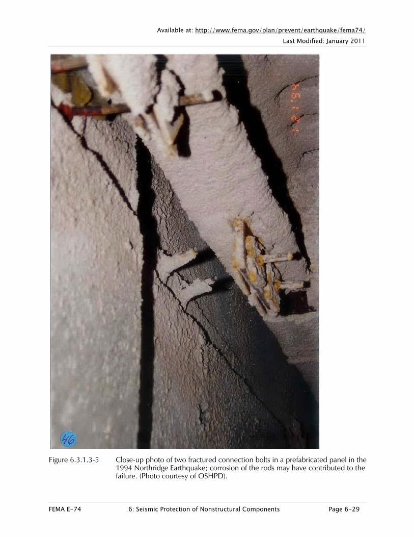
Figure 6.3.1.3-5 Close-up photo of two fractured connection bolts in a prefabricated panel in the 1994 Northridge Earthquake; corrosion of the rods may have contributed to the failure. (Photo courtesy of OSHPD).

Available at: http://www.fema.gov/plan/prevent/earthquake/fema74/ Last Modified: January 2011
FEMA E-74 6: Seismic Protection of Nonstructural Components Page 6-30
Figure 6.3.1.3-6 Residential building with precast concrete corridor and balcony railing panels. Some panels were damaged and subsequently many were removed to prevent falling. Location in Rancaqua, Chile 154 miles northeast of the epicenter; estimated PGA of 0.3g during the 2010 magnitude-8.8 Chile Earthquake (Photo courtesy of Antonio Iruretagoyena, Rubén Boroschek & Associates).
Figure 6.3.1.3-7 Numerous precast panels removed to prevent falling; detail from residential building in Rancagua, Chile above. These panels had a bearing seat at the center and supported on steel dowels at either end (Photo courtesy of Eduardo Fierro, BFP Engineers).

Available at: http://www.fema.gov/plan/prevent/earthquake/fema74/ Last Modified: January 2011
FEMA E-74 6: Seismic Protection of Nonstructural Components Page 6-31
SEISMIC MITIGATION CONSIDERATIONS
Precast panel connections and panel joints require specialized design based on the expected inter-story drift of the structural system supporting them or 0.5 inch, whichever is greater. The connections must be detailed with sufficient ductility and rotation capacity to prevent failure. Typically, the panels are seated on two bearing connections at either the top or bottom floor and then have “push-pull” connections at the adjacent floor which resist out-of-plane loading but move laterally in the plane of the panel. In this way, the panels move with the floor where the bearing connections are located and the drift is accommodated by the rod at the “push-pull” connection.
Architectural Design for Earthquake, A Guide to Nonstructural Elements, (Charleson, 2007) has a detailed discussion of issues related to exterior cladding. Sliding connections with slotted or oversized holes are commonly used in New Zealand as an alternative to push-pull connections.

Available at: http://www.fema.gov/plan/prevent/earthquake/fema74/ Last Modified: January 2011
FEMA E-74 6: Seismic Protection of Nonstructural Components Page 6-32
MITIGATION DETAILS
Figure 6.3.1.3-8 Precast spandrel panel in San Francisco parking garage supported by bearing connections near top of panel (left) and slotted connections at bottom of panel (right); panels have four connections each. The remnants of a previous nonductile connection detail are visible in the photo at left (Photo courtesy of Cynthia Perry, BFP Engineers).

Available at: http://www.fema.gov/plan/prevent/earthquake/fema74/ Last Modified: January 2011
FEMA E-74 6: Seismic Protection of Nonstructural Components Page 6-33
Figure 6.3.1.3-9 Prefabricated panels (ER).

Available at: http://www.fema.gov/plan/prevent/earthquake/fema74/ Last Modified: January 2011
FEMA E-74 6: Seismic Protection of Nonstructural Components Page 6-34
6.3 ARCHITECTURAL COMPONENTS
6.3.1 EXTERIOR WALL COMPONENTS
6.3.1.4 GLAZING
Glazing includes glass curtain walls on multistory buildings, large storefront windows, as well as small, operable wood framed windows. Glass may be annealed, heat-strengthened, tempered, laminated or in sealed, insulating glass units. Glazing can be installed using either wet or dry glazing methods. Any of these may pose a significant falling hazard if not designed to accommodate seismic forces and displacements.
TYPICAL CAUSES OF DAMAGE
Glazing assemblies are sensitive to both accelerations and deformations and are subject to both in-plane and out-of-plane failures. Glazing is particularly vulnerable in flexible structures with large inter-story drifts; large storefront windows are also vulnerable. Glass can fall in shards, shatter into small pieces, or broken panes may be held in place by film.

Available at: http://www.fema.gov/plan/prevent/earthquake/fema74/ Last Modified: January 2011
FEMA E-74 6: Seismic Protection of Nonstructural Components Page 6-35
Damage Examples
Figure 6.3.1.4-1 Shard of broken untempered glass that fell several stories from a multistory building in the 1994 Northridge Earthquake (Photo courtesy of Wiss, Jenney, Elstner Associates).

Available at: http://www.fema.gov/plan/prevent/earthquake/fema74/ Last Modified: January 2011
FEMA E-74 6: Seismic Protection of Nonstructural Components Page 6-36
Figure 6.3.1.4-2 Scenes in Ferndale, California following the 2010 magnitude-6.5 Eureka Earthquake. 50% of the glazing on Main Street was cracked (Photos courtesy of Bret Lizundia, Rutherford & Chekene).

Available at: http://www.fema.gov/plan/prevent/earthquake/fema74/ Last Modified: January 2011
FEMA E-74 6: Seismic Protection of Nonstructural Components Page 6-37
Figure 6.3.1.4-3 Glazing damage was observed in many residential and commercial buildings and hospitals throughout central Chile following the 2010 magnitude-8.8 Chile Earthquake (Photo courtesy of Eduardo Miranda, Stanford University).

Available at: http://www.fema.gov/plan/prevent/earthquake/fema74/ Last Modified: January 2011
FEMA E-74 6: Seismic Protection of Nonstructural Components Page 6-38
Figure 6.3.1.4-4 Glazing damage, due in part to pounding with the structure at right during the 2010 Chile Earthquake (Photo courtesy of Antonio Iruretagoyena, Rubén Boroscheck & Associates).

Available at: http://www.fema.gov/plan/prevent/earthquake/fema74/ Last Modified: January 2011
FEMA E-74 6: Seismic Protection of Nonstructural Components Page 6-39
Figure 6.3.1.4-5 Overhead glazing damage from the 2010 Chile Earthquake (Photo courtesy of Eduardo Miranda, Stanford University).

Available at: http://www.fema.gov/plan/prevent/earthquake/fema74/ Last Modified: January 2011
FEMA E-74 6: Seismic Protection of Nonstructural Components Page 6-40
Figure 6.3.1.4-6 Broken glass and bent window mullions in flexible building which experienced large inter-story drift in the 1994 Northridge Earthquake (FEMA 310, 1998).

Available at: http://www.fema.gov/plan/prevent/earthquake/fema74/ Last Modified: January 2011
FEMA E-74 6: Seismic Protection of Nonstructural Components Page 6-41
SEISMIC MITIGATION CONSIDERATIONS
The design of glazing assemblies depends on the calculated inter-story drift for the building. Glazing generally performs better with stiffer structural systems that have lower inter-story drift or where larger edge clearances are provided at the mullions. The building code ASCE/SEI 7-10 and rehabilitation standard ASCE/SEI 41-06 Seismic Rehabilitation of Existing Buildings, (ASCE, 2006) include minimum requirements for Δfallout, the relative displacement that causes the glass to fall from the glazing assembly, as a multiple of the design displacement and the importance factor.
The term safety glass refers to tempered or laminated glazing and is required by code in a number of applications such as glazing in or adjacent to exits, within 10’ of a walking surface, etc. ANSI A97.1 Safety Glazing Materials Used in Buildings (ANSI, 2004) is the standard that defines different kinds of safety glass. Use of tempered glass will greatly reduce the seismic hazard because tempered glass breaks into small dull fragments instead of large hazardous shards. Tempered glass is required within 10’ above a walking surface under some circumstances; check applicable code requirements. Laminated glass will typically remain in place when broken and will prevent people or objects from falling through the opening. Wired glass with a grid of steel wire embedded in the pane is an option for some situations where fire and impact rating are not also required. Storefront windows are often vulnerable as the windows occupy a large structurally unsupported area at the ground floor, often resulting in soft story or torsion problems. Use of laminated glass for storefront windows reduces the seismic risk and also increases protection from burglary and vandalism.
Plastic films that help hold glass fragments together even if the pane breaks are available. These films may reduce the seismic risk particularly where glazing is directly over an exit way, within 10’ of an exit way, or along interior corridors. Such films may be a cost effective way to retrofit an existing pane of glass and are often installed for other reasons, such as security or reducing solar heat gain. Extending the film over the edge of the surrounding frame is advisable not only to hold broken fragments in place but also to prevent the entire pane from falling out.
Avoid placing beds, desks, chairs or couches that are typically occupied many hours a day near large plate glass windows.
Liberal use of landscaping strips or areas with restricted pedestrian access may help to reduce the seismic risk beneath large glass panes or tall curtain walls.

Available at: http://www.fema.gov/plan/prevent/earthquake/fema74/ Last Modified: January 2011
FEMA E-74 6: Seismic Protection of Nonstructural Components Page 6-42
MITIGATION DETAILS
Figure 6.3.1.4-7 Glazed exterior wall system (ER).