aalborg universitet energy reduction in buildings in temperate
TRANSCRIPT
Aalborg Universitet
Energy reduction in buildings in temperate and tropic regions utilizing a heat lossmeasuring deviceSørensen, Lars Schiøtt
Published in:Proceedings of the 2nd World Sustainability Forum
Publication date:2012
Document VersionEarly version, also known as pre-print
Link to publication from Aalborg University
Citation for published version (APA):Sørensen, L. S. (2012). Energy reduction in buildings in temperate and tropic regions utilizing a heat lossmeasuring device. In Proceedings of the 2nd World Sustainability Forum: Energy Efficiency MDPI.
General rightsCopyright and moral rights for the publications made accessible in the public portal are retained by the authors and/or other copyright ownersand it is a condition of accessing publications that users recognise and abide by the legal requirements associated with these rights.
? Users may download and print one copy of any publication from the public portal for the purpose of private study or research. ? You may not further distribute the material or use it for any profit-making activity or commercial gain ? You may freely distribute the URL identifying the publication in the public portal ?
Take down policyIf you believe that this document breaches copyright please contact us at [email protected] providing details, and we will remove access tothe work immediately and investigate your claim.
Downloaded from vbn.aau.dk on: november 16, 2018

Article
Energy reduction in buildings in temperate and tropic regions
utilizing a heat loss measuring device
Lars Schiøtt Sørensen, Senior Researcher, Ph.D.
Danish Building Research Institute, Aalborg University, Denmark; E-Mail: [email protected];
Tel.: +45-29-10-0296; Tel.: +45-48-47-1718.
Received:
Global energy efficiency can be obtained in two ordinary ways. One way is to make
improvement on the energy production and supply side, and the other way is, in general, to
reduce the consumption of energy in society. This paper has focus on the latter and especially the
consumption of energy for heating and cooling our houses. There is a huge energy-saving
potential in this area for reducing both the global climate problems as well as economy
challenges.
Heating of buildings in Denmark counts for approximately 40% of the entire national energy
consumption. For this reason, a reduction of heat losses from building envelopes are of great
importance in order to reach the Bologna CO2-emission reduction targets. Upgrading of the
energy performance of buildings is a topic of huge global interest these years [14]. Not only
heating in the temperate and arctic regions are important, but also air conditioning and
mechanical ventilation in the “warm countries” contribute to an enormous energy consumption
and corresponding CO2 emission.
In order to establish the best basis for upgrading the energy performance, it is important to make
measurements of the heat losses at different places on a building facade, in order to optimise the
energy performance. This paper presents a method for measuring the heat loss by utilising a U-
value meter [2]. The U-value meter measures the heat transfer in the unit W/Km2 and has been
used in several projects to upgrade the energy performance in temperate regions. The U-value
meter was also utilised in a EUDP project focusing on renovation of houses from the 1960s and
1970s. The U-value meter is now planned to be utilized in the tropics for measuring the thermal
performance of facades with the aim to reduce the costs to air conditioning. In this context we
introduce the initiation of a project between the National University of Singapore, Aalborg
University, Denmark and HT-Meter, the latter as the U-value meter developer company.
Keywords: energy reduction of buildings, heat loss measuring; energy performance; heat
loss measuring device; temperate and tropic regions, CO2 emission, global climate, world
economy.

2
1. Introduction
1.1. Introduction to Energy Performance Upgrading
Around the world, building owners are able to decrease heating costs remarkably with a rational
upgrading of the energy performance of their buildings. This is demonstrated by measurements of
different houses, built in different decades of the past century. A few examples are described for
houses from the 1960s and 1970s in this paper.
Heating accounts for some 40% of the total Danish energy consumption which, therefore, represents
vast potential savings. The U-value meter is an ideal instrument by which to establish the locations of
the greatest heat loss on a facade, arming owners with the knowledge of where best to concentrate
efforts to insulate and optimise savings. In this way, the overall costs of upgrading the energy
performance can be reduced considerably, and an optimal relation between investment and savings
achieved.
The mean ambient temperature in Denmark has increased by about 1.2 ºC during a period of
approximate 130 years [4]. The period encompasses a part of the industrial revolution, which began
during the second half of the 18th century. Upgrading the energy performance of as many
houses as possible worldwide would benefit the environment by slowing and decreasing the
consequent global heating.
A EUDP project with the aim of designing standardised solutions for energy renovation of facades
is currently in progress [6]. In the project, the U-value meter is utilised to measure representative
U-values for a number of different residential houses built in the period from 1960s-1970s and
representing over 90% of private houses in Denmark. The measurements will be compared with the
U-value requirements for the respective construction periods. From this approach we are able to
calculate the potential heat savings compared with the present U-value requirements, as per the Danish
Building Regulations. Furthermore, we compare heat consumption before and after upgrading the
energy performance where the developed standard solutions for retrofitting facades are used. The
involved parties are, among others, HT-Meter ApS., Saint-Gobain Isover A/S together with DTU. The
project aims to minimise the emission of CO2 caused by unnecessarily large energy consumption for
heating [2,6].
1.2. Introduction to U-value Meter
Measurements of U-values have traditionally been made in laboratories with the assistance of heat
flux measurements and heat conductivity apparatus [3]. Such measurement methods are complicated
and laborious because the target wall or window elements must be transported to the laboratory and
mounted into the test arrangement designed for the experiment. Then controlled amounts of energy,
resulting in rises in temperature, must be supplied to the test arrangement in order to initiate the
essential heat transfer in the test piece.

3
Fourier’s law = k∆T/∆x (a special 1D form of Fourier’s law [5,17]) representing heat conduction,
only applies to the steady-state. Laboratory measurements of U-values can take several hours or even
days before a steady-state measurement can be obtained.
The time required to reach a steady-state situation depends primarily on the thermal inertia of the
test piece, i.e., material-based properties such as heat capacity, density, thermal conductivity and
material thickness. After that, measurements of the heat flux are typically carried out for a relatively
long period of time. This is done by means of measurements in test arrangements, which are large in
volume, typically several cubic meters. The heat flux is measured by holding a constant temperature
level on the heat receiving side, i.e., the cold side of the test piece. The basis for finding heat
conductivities practically is by means of laboratory-based measurements on conditioned test specimens
brought to steady state by means of a plate apparatus with a protective ring or with a heat flux meter in
accordance with DS/EN 12664 or DS/EN 12667. The results of the measurements refer to a mean
temperature of 10 ºC. Common to the aforementioned measuring methods is the problem of a
transition insulation factor at the bounding surfaces on the two sides of a test piece. The surface
temperatures of the test piece are not identical to the air temperatures very near to its surfaces. This
problem is addressed in different ways by state-of-the-art technology and with reasonable accuracy [3].
With the newly developed U-value meter, such a process can be omitted and U-values can be
measured directly on site. See Figure 1 for a picture of the U-value meter.
Figure 1. U-value measurement on outer wall. The figure also shows an insulated acclimation
suitcase, in which the meter is placed between the individual measurements.
This apparatus is based on a principle where the heat is ‘trapped’ by a heat absorption sensor
(copper plate) when it leaves the outdoor surface of the test piece. A copper plate is used, as the
absorption sensor due to its high thermal diffusivity and high conductivity [2,3].
The temperature of the heat absorption sensor is measured continuously over a short period of time,
and from the relative increase of energy the U-value can be calculated. The system is separated from
the surrounding environment by a highly insulating material, with low thermal diffusivity and low
conductivity.

4
Heat transfer occurs by thermal radiation, conduction and convection and the apparatus is designed
to ensure that these constituent energy components are collected by the sensor plate. In fact, in the case
of windows, radiation alone can account for as much as 70% of its total heat loss. However, this value
can be reduced drastically with a low emissivity coating: windows with and without these coatings can
be handled by the U-value meter.
Heat conduction is the molecular oscillation transport whereas radiation is electromagnetic energy
transport. In the U-value meter it is chosen to transform the heat conduction (conduction in a solid) to
convection in a fluid (an air gap in front of the copper plate is included to do this). That is to say, the
transfer process to the heat absorption sensor is changed from conduction to convection through the air
gap. It is important to ensure that the temperature of the heat absorption sensor is identical with the
outdoor temperature just before a heat transmission coefficient (i.e. U-value) measurement is initiated
[3].
The heat absorption sensor is coated with a material of high heat absorption capacity to secure a
quick and effective heat transfer from test piece to heat absorption sensor. Heat transfer occurs by
convection as well as thermal radiation via the described air gap. Following this procedure, there is no
ongoing heat transfer from the surface of the test piece to the heat absorption sensor by direct contact.
By the new ‘air gap’ technique, developed with this U-value meter, the problems of transition
insulation factor and surface temperature are eliminated, creating more accurate results. At the same
time, geometrical inaccuracies at the surface of the test piece are eliminated by the air gap. These
would, by direct contact, cause irregular heat conduction between the two surfaces, i.e., between the
test piece and the copper plate.
The coating is placed on the side of the heat absorption sensor facing the test piece. On the opposite
side, i.e. facing away from the heat absorption sensor, a reflecting layer is placed to ensure energy
transmitted to the heat absorption sensor is trapped and kept inside during the test.
Behind the reflecting foil is a heat insulating layer, of relatively thick dimensions, and low thermal
conductivity and diffusivity as basic thermal properties [2,3].
With this invention a very good accuracy is achieved for measuring transmission coefficients
(U-values). The accuracy of the results lies between +/–5% from the ‘correct’ result according to
information from different manufacturers of building components, tested via laboratory.
Another advantage of the invention is that the U-values are measured on site and in real time, giving
current information of transmission coefficients for a particular building as opposed to the ‘new
building element’ U-value. This is important for several reasons: first of all, the moisture content
changes in a building element, an outer wall for instance, during the years in which the element is a
part of the building. Moisture levels influence the U-value, depending on the relative humidity and the
type of material in focus. Furthermore the insulation in an outer wall can ‘fall down’ a bit during the
years resulting in poorly distributed insulation. For windows the glazing can puncture and the
insulating effect is reduced significantly [2,3].
5
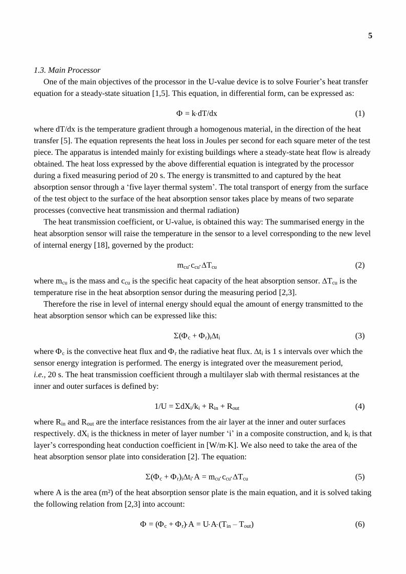
1.3. Main Processor
One of the main objectives of the processor in the U-value device is to solve Fourier’s heat transfer
equation for a steady-state situation [1,5]. This equation, in differential form, can be expressed as:
where dT/dx is the temperature gradient through a homogenous material, in the direction of the heat
transfer [5]. The equation represents the heat loss in Joules per second for each square meter of the test
piece. The apparatus is intended mainly for existing buildings where a steady-state heat flow is already
obtained. The heat loss expressed by the above differential equation is integrated by the processor
during a fixed measuring period of 20 s. The energy is transmitted to and captured by the heat
absorption sensor through a ‘five layer thermal system’. The total transport of energy from the surface
of the test object to the surface of the heat absorption sensor takes place by means of two separate
processes (convective heat transmission and thermal radiation)
The heat transmission coefficient, or U-value, is obtained this way: The summarised energy in the
heat absorption sensor will raise the temperature in the sensor to a level corresponding to the new level
of internal energy [18], governed by the product:
where mcu is the mass and ccu is the specific heat capacity of the heat absorption sensor. Tcu is the
temperature rise in the heat absorption sensor during the measuring period [2,3].
Therefore the rise in level of internal energy should equal the amount of energy transmitted to the
heat absorption sensor which can be expressed like this:
where c is the convective heat flux and r the radiative heat flux. ti is 1 s intervals over which the
sensor energy integration is performed. The energy is integrated over the measurement period,
i.e., 20 s. The heat transmission coefficient through a multilayer slab with thermal resistances at the
inner and outer surfaces is defined by:
where Rin and Rout are the interface resistances from the air layer at the inner and outer surfaces
respectively. dXi is the thickness in meter of layer number ‘i’ in a composite construction, and ki is that
layer’s corresponding heat conduction coefficient in [W/mK]. We also need to take the area of the
heat absorption sensor plate into consideration [2]. The equation:
where A is the area (m²) of the heat absorption sensor plate is the main equation, and it is solved taking
the following relation from [2,3] into account:
= kdT/dx (1)
mcuccuTcu (2)
(c + r)iti (3)
1/U = dXi/ki + Rin + Rout (4)
(c + r)itiA = mcuccuTcu (5)
= (c + r)A = UA(Tin – Tout) (6)

6
Tin and Tout are the absolute indoor and outdoor temperatures, respectively. From (6) we are able to
get the U-value expression as:
By multiplying numerator and denominator with the measuring time t (= 20s) and utilising the
relations given by (5) noting that t = ti, we get:
Therefore, before a measurement is started, we need to know the temperatures on both sides of the
test object i.e., Tin and Tout respectively. The apparatus is able to measure Tout automatically.
It is beyond the scope of this presentation to present in detail the form of the related data processing
algorithm in the main processor, including output validation. However, the data processing aims to
solve the above described thermo-physics. For further information see [2].
2. EUDP project
In Denmark, there is a great energy saving potential in houses built in the 1960s and 1970s. Special
scrutiny is given to these houses since they account for a large part of the total residential dwellings
[15,16]. In principle, it is possible to upgrade the energy performance of all types of housing up to
modern requirements. It just depends on a sufficient increase of insulation in facades and ceiling,
replacing traditional double-glazing with energy-saving glazing of low U-value (<1.1 W/m2K),
mounting draught-exclusion strips around doors and windows, optimising heating systems, changing to
energy saving light sources and, crucially, on willingness to pay up-front costs for hidden benefits
[10,12,13].
During a EUPD project [6] with participants from the Technical University of Denmark, Saint-
Gobain, Weber, Isolink, HT-Meter and others, measurements were made on typical residential houses
from the 1960s and 1970s. As an example Table 1 presents measurement results (U-values) for a 145
m2 house built in 1964, located at Christianshøjvej, Kirke Værløse, Denmark. The house was partly
rebuilt and extended in 2005. Outer walls are made of solid aircrete blocks. Some of the outer walls
were insulated (inside) during the conversion in 2005. Heating of the house was done via a new
condensing natural gas boiler. The U-measurements were made on 6 April 2011 between 9:30 AM and
12.10 PM by the U-value Meter (software version 1.60) together with a RayTek laser/infrared
temperature measuring device. Weather conditions were calm, with wind speed < 5 m/s, no rain and
with outdoor temperatures ranging from 8.0 ºC at 9:30 AM and increasing to 10.0 ºC at 12:10 PM. The
U-vale measurements were accompanied by thermography, and a few examples of these are shown in
Figures 3 to 5. A plan drawing of the house is shown in Figure 2.
U = (c + r)A/(Tin – Tout)A (7)
U = mcuccuTcu/(Tin – Tout)At (8)

7
Figure 2. One of the test houses involved in the EUDP project.
Tin is higher than Tout for the situations in figures 3 to 5. Figure 3 and 4 are thermographics taken from
outside the building and figure 5 is from inside the building. The dark shaded (blue/violet) areas on
figure 3 and 4 represents cold surfaces and therby more heat insulated than the yellow/orange areas
with higher outside surface temperatures caused by poor insulation.
Figure 3. Poorly insulated window/door section along a corridor that connects the main house with an
annex. The U-value is measured to be U-value=1.44 (Id 1, the wood parapet). The outer wall next to
the wind/door section was measured to be U-value=0.80 (Id 2). See Table 1 for measured U-values.

8
Figur 4. Gable (west) with window to the bedroom. This room`s outer wall was previously insulated
from inside. However, a thermal bridge interruption was omitted along the floor concrete slab and
therfore the socket shows orange on the thermography to the right. The U-value was measured to 1.03
(Id 19) compared with the insulated outerwall U-value=0.32 (Id 22), see Table 1.
At the thermography on figure 5, the dark shaded areas also represents cold surfaces, but with low heat
insulation. The low insulation gives rise to low surface temperatures inside. The yellow and orange
areas represent better insulated areas and therefore capable to keep the heat inside the room which in
turn results in higher surface temperatures.
Figur 5. The transition between the wall and the floor is acceptable. No leaks were registered in this
door. The dark shades of the door indicate cold surfaces and a relatively large heat loss through the
door. That corresponds to a high U-value, which is confirmed by Table 1, where the door is measured
to U-value = 1.72 (Id 9) compared with the outer wall’s U-value = 0.89 (Id 11).

9
Table 1. Measurements of U-values for a typical Danish residential house from 1960s
Id Object Tin (°C) Remark U-value (W/m2K)
1 Parapet 21.9 2 thin wooden boards with air/insulation
between. 3 cm thick in total
1.44
2 Outer wall 23.0 Measured at 70 cm height 0.80
3 Outer wall 22.4 Measured at 1.5 m height 0.84
4 Outer wall 23.3 Measured at 1.5 m height 0.88
5 Pane 23.3 Measured at the middle of the pane 1.24
6 Outer wall 23.3 Measured at 1.5 m height 0.87
7 Outer wall 23.5 Measured at 1.5 m height 0.81
8 Outer wall 23.5 Measured at 1.5 m height 0.85
9 Exterior door 22.0 Door made of 4 cm thick wood (possibly
teak)
1.72
10 Pane 22.3 Measured at the middle of the pane 1.30
11 Outer wall 22.3 Measured at 1.5 m height 0.89
12 Beam 22.3 Window lintel (lightweight concrete) 1.12
13 Edge of wall 22.3 No significant peripheral effects were
measured
0.91
14 Exterior door 22.0 Door made of 4 cm thick wood (possibly
teak)
1.78
15 Wall 22.4 Wall between the garage and living room 0.32
16 Outer wall 20.5 Outer wall of utility room/laundry room
(facade)
0.26
17 Outer wall 20.5 Outer wall of utility room/laundry room
(gable)
0.29
18 Outer wall 20.5 Outer wall of utility room/laundry room
(gable)
0.29
19 Socket 21.9 Measured at the center of the base 1.03
20 Outer wall 22.7 Built-in cupboard stood up against this
wall. Measured at 40 cm height
0.36
21 Pane 22.7 Measured at the middle of the pane 1.16
22 Outer wall 22.7 Measured at wall section below the
window
0.32
23 Outer wall 22.7 Measured at 40 cm above socket level 0.20
24 Outer wall 22.7 Measured 80 cm above bottom of wall 0.23

10
Based on the measured U-values in Table 1, thermography and measurements of surface areas for
the different types of structures and building elements (outer walls, exterior doors, windows etc.), it is
possible to calculate the potential savings in energy (Q) for heating. If the upgraded energy
performance complies with the current requirements to U-values stipulated in the Building Regulations
is implemented [7,8,9], we can write:
Q = it = UiAi(Tin – Tout) t (9)
Ui and Ai are U-values and areas, respectively, for the building elements (windows, exterior doors,
outer walls). t represents the time (could be set to a year) if we use an average indoor temperature and
the year mean temperature. The Q-equation (9) is calculated for measured Ui as well as for required Ui-
values, and the difference (Q) represents the saved of energy.
The budget for upgrading the energy performance of this house was about DKK 470,000 (USD
94,000). The energy consumption (heat and electricity) totalled as much as DKK 39,000 (USD 7,800)
per year (including heat for a pool). Natural gas for heating in year 2009/2010 totalled 1,906 m3
(heating of house excl. pool) corresponding to 145 kWh/m2 which is much more than required to a
new house today in Denmark (approximately 65-70 kWh/m2 [9]). A small part of the house (a corridor
and a bedroom) was heated by electricity with consumption in 2010 of 1,354 kWh. Indoor temperature
(year average) was 22 ºC. The saving potential on heating (gas consumption alone) was DKK 10,800
(USD 2,160) per year corresponding to approximately 60% saved on the heat expenses for the main
house, disregarding the swimming pool. This saving potential corresponds to the below listed measures
for upgrading the energy performance [6]:
Outer walls including sockets are insulated with 195 mm mineral wool which is plastered.
One exterior door replaced by a modern entrance door with low U-value. The other exterior
door is removed and the opening closed and insulated as the rest of the façade.
House entrance was insulated with 100 mm insulation
Gables and foot of roof were insulated with good connection to the ceiling insulation
Digging up soil around the concrete foundation and in top, new foundation blocks made of
lightweight concrete are established and insulated with phenolic foam (PF).
The existing windows (with low-energy glazing) are moved out to align with the façade.
Installation of mechanical ventilation (balanced) aggregate with heat recovery
Airtightening of the ceiling and between ceiling and outer walls.
Insulation of bedroom (previously insulated from inside to a certain level)
Every upgrades of energy performance must be conducted with special care to the actual building
physics. The upgrades should off course not introduce new problems such as increased moisture level
in the building [11].
A number of other measurements were made on different buildings during the last seven years,
partly in parallel with the development of the apparatus and integrated OS software. Other examples

11
on measurements are presented in [2]. In the same reference you can find a discussion of the
limitations and uncertainties of the U-value meter.
3. Planned measurements in tropic regions
A research cooperation about thermal performance of facades in tropics is initiated with SERIS
(Solar Energy Research Institute) at NUS in Singapore. After a number of phone meetings concerning
proposals, agreements (including scope of work), non-disclosure agreement etc., a first meeting in
Singapore is planned together with SERIS. U-value measures a façades and an introduction course on
how to use the U-value meter will cover the main parts of the meeting. A strategy for the coming
measurements of the thermal performance of facades will be outlined. A number of houses in
Singapore are the focus of the measurements. The measured U-values will be the basis for future
proposals of thermal improvements of different types of facades, panes etc. The outcome of the project
will be published in interested journals and/or at conferences by the end of the cooperation.
4. Conclusions
Energy efficiency, energy reduction and upgrading of the energy performance was investigated. A
new heat loss measuring device, called a U-value meter, has been developed. The device was invented
in 2001 and the first application to the Danish Patent Office took place in March 2002. A Danish
patent was granted in 2009 (Patent number 176757). An international patent application was filed in
March 2003. The device can be utilised as a stand-alone apparatus, or in combination with
thermography equipment, the latter in order to get a picture of the distribution of hot and cold locations
of a building facade. However, since thermography only gives a picture of the surface temperatures,
and not the heat loss distribution, the need arises for a heat loss measuring device. The device
measures heat losses through the facades in the SI unit [W/m2K]. By means of the measuring device, it
is possible to achieve a more cost-effective building renovation. It is possible to check whether heat
transmission coefficients (U-values) meet the requirements as stipulated in the Danish Building
Regulations. The corresponding potential reduction of the energy consumption can be calculated. A
huge energy saving potential for residential houses is demonstrated during a EUDP project in a
temperate region (Denmark). The initiation of a project in a tropic climate in cooperation with NUS is
introduced.
References and Notes
1. Sørensen, L.S. Varmeudveksling under brandforløb. In Brandfysik og Brandteknisk Design af
Bygninger, 1st ed.; Polyteknisk Forlag: Copenhagen, Denmark, 2004; pp. 167-198, 473-496.
2. Sørensen L.S. Energy Renovation of Buildings Utilizing the U-value Meter, a new Heat Loss
Measuring Device. HT-Meter, Fredensborg. Published in the MDPI-journal Sustainability, ISSN
2071-1050, January 2010.
3. Sørensen, L.S; U-value Meter (Transmission Coefficient Measuring Apparatus). EP Application.
Number EP1347289; March 2003; pp. 1-13.

12
4. Denmark Meteorological Institute. Available online: www.dmi.dk.
5. Incropera & DeWitt, Fundamentals of Heat and Mass Transfer, 6th ed.; Wiley: Somerset, NJ,
USA, 2006; Chapter 9.
6. EUDP-2009-II: Development of standard solutions for energy-extensive building envelope
renovation of existing buildings from the period 1960-80. A Development and demonstration
Project with financial support from the Energy Technological Development and Demonstration
Program (EUDP).
7. Aggerholm, S. and Grau, K. Bygningers energibehov (SBi-anvisning 213). Statens Byggeforsk-
ningsinstitut. Danish Building Research Institute 2005.
8. Dansk Standard. Beregning af bygningers varmetab. DS 418:2002. Charlottenlund 2002.
9. SBi. Anvisning om Bygningsreglement 2010 (SBi-anvisning 230). Statens Byggeforsknings-
institut. Danish Building Research Institute 2010, Aalborg University.
10. DS/EN ISO 10077-2, Termisk ydeevne for vinduer, døre og skodder - Beregning af varmetrans-
mission-Del 2: Numerisk metode for rammer. p. 262.
11. Byg-Erfa. Dampspærrer i klimaskærmen – fugttransport og materialer. BYG-ERFA Erfaringsblad
(39) 071029. Ballerup. Lokaliseret på https://byg-erfa.dk/dampspaerrer-fugttransport 2007.
12. Dansk Standard. Termisk isolering af tekniske installationer (DS 452:1999). Charlottenlund 1999.
13. Dansk Standard. Kuldebroer i bygningskonstruktioner: Varmestrømme og overfladetemperaturer.
Detaljerede beregninger (DS/EN ISO 10211:2008). Charlottenlund 2008.
14. Europaparlamentets og Rådets direktiv 2002/91/EF af 16/12/2002: Direktiv om bygningers
energimæssige ydeevne. De Europæiske Fællesskabers Tidende, L65-70, 4.1.2003. Lokaliseret på
http://eur-lex.europa.eu. 2003.
15. Marsh, R. Arkitektur og energi: mod en 2020-lavenergistrategi. Statens Byggeforskningsinstitut.
Danish Building Research Institute, Aalborg University. Hørsholm. Lokaliseret på
http://www.sbi.dk/arkitektur/beredygtighed/arkitektur-og-energi-mod-en-2020-lavenergistrategi.
2011
16. Munch-Andersen, J. Efterisolering af etageboliger (SBi-anvisning 221). Statens Byggeforsk-
ningsinstitut. Danish Building Research Institute 2010, Aalborg University. Hørsholm. Lokaliseret
på http://anvisninger.dk/221 2010.
17. Holman, J.P. Heat Transfer, McGraw-Hill Inc. 1997.
18. Both, E. and Christiansen, G. Termodynamik. Den private Ingeniørfond. 1995.