5060 a/e/ax/ex - tech tire repairs and service - syracuse€¦ · coats 5060 tire changer • 3...
TRANSCRIPT

5060 A/E/AX/EXTire ChangerFor servicing single piece automotive and mostlight truck tire/wheel assemblies
1601 J. P. Hennessy Drive, LaVergne, TN USA 37086-3565 615/641-7533 800/688-6359 Manual Part No.: 8182882 15HENNESSY INDUSTRIES INC. Manufacturer of AMMCO®, COATS® and BADA® Automotive Service Equipment and Tools. Revision: 02/98
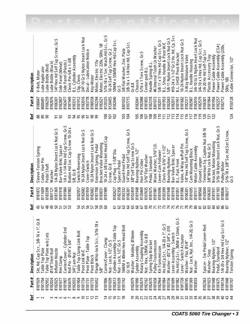
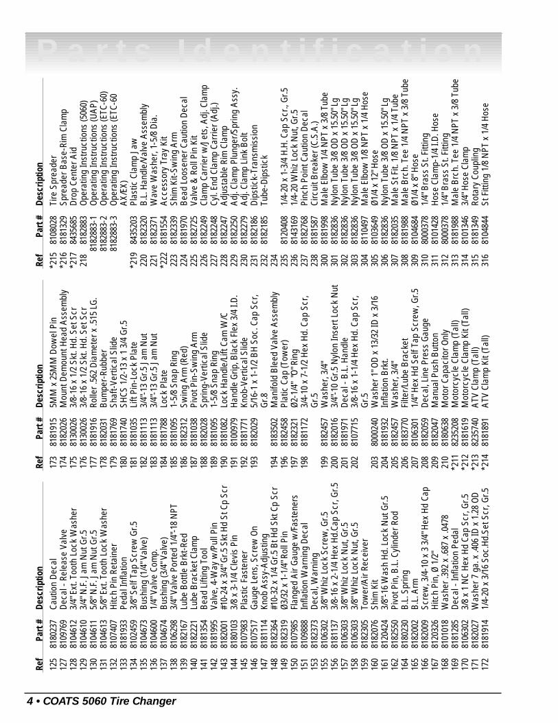
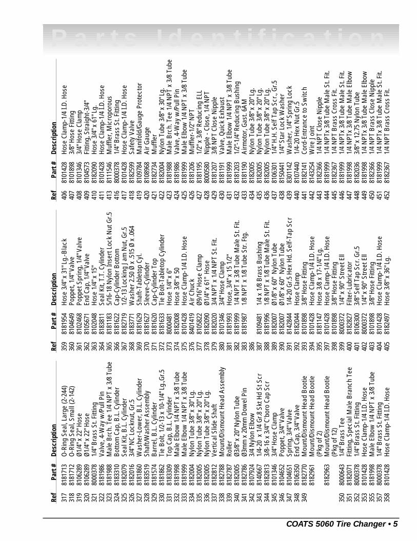
Parts Identification
READ these instructions before placing unit inservice KEEP these and other materials deliveredwith the unit in a binder near the machine forease of reference by supervisors and operators.
®
2 • COATS 5060 Tire Changer
Parts IdentificationTable of Contents
Parts List . . . . . . . . . . . . . . . . . . . . . . . . .3 - 6
Tire Changer Exploded View . . . . . . . . . . . .7
Air Motor Model . . . . . . . . . . . . . . . . . . . . .8
Electric Motor Model . . . . . . . . . . . . . . . . . .9
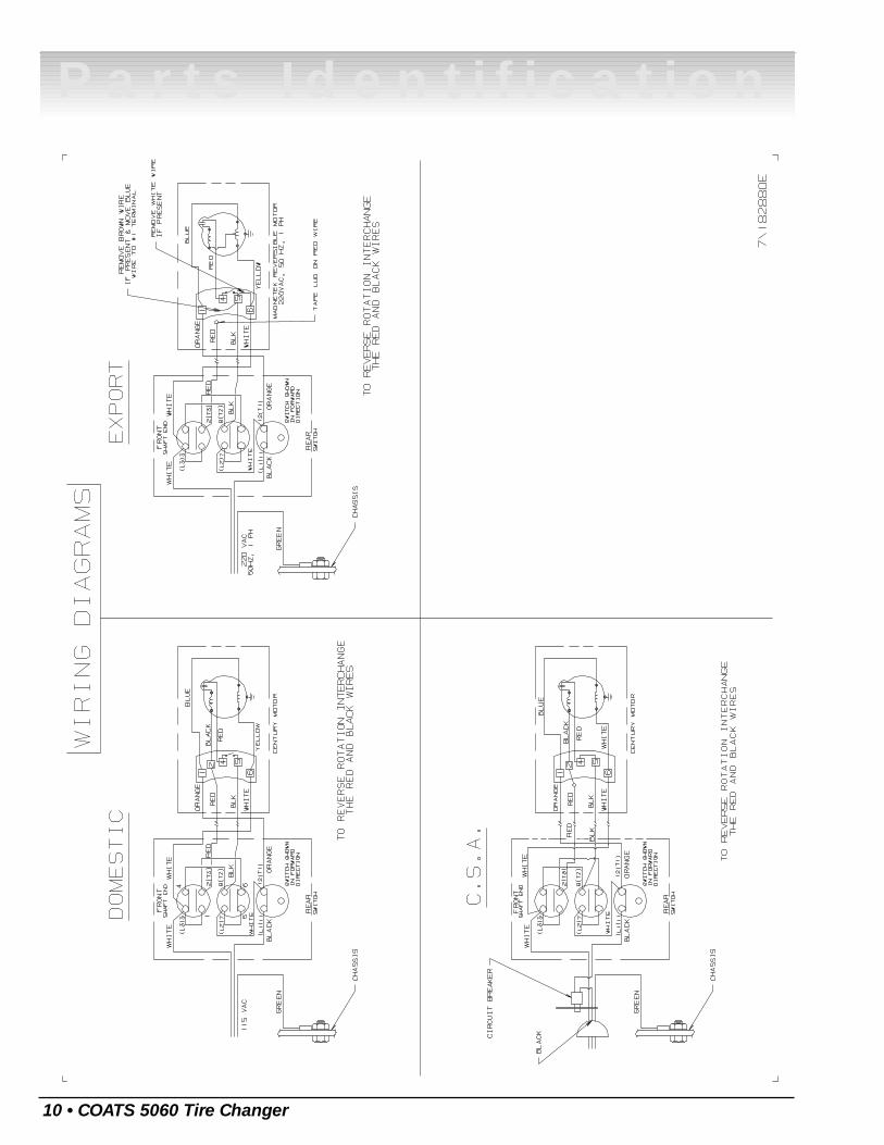
Wiring Diagrams . . . . . . . . . . . . . . . . . . . .10
Notes . . . . . . . . . . . . . . . . . . . . . . . . . . . . .11
Hennessy Industries, Inc.1601 J.P. Hennessy DriveLaVergne, TN 37086-3565(615) 641-7533 or (800) 688-6359www.ammcoats.com
For additional tire, wheel, and/or inflation informationcontact the following:
Rubber Manufacturers Association
1400 K Street N. W.Washington, DC 20005(202) 682-4800www.rma.com
Tire Guides, Inc.
The Tire Information Center1101-6 South Rogers CircleBoca Raton, FL 33487-2795(561) 997-9229www.tireguides.com
COATS 5060 Tire Changer • 3
Parts IdentificationRe
fPa
rt #
Des
crip
tion
181
8192
9Sk
t. Hd
. Cap
Scr
., 3/
8-16
x 1
", Gr
.82
8181
704
Tabl
e To
p Pl
ate
8182
952
Tabl
e To
p Pl
ate
w/o
Jet
s3
8182
024
Ø1/4
" Ste
el B
all
481
8202
5In
flatio
n N
ozzle
581
8167
7Ri
m C
lam
p6
8181
907
Carr
ier/C
over
- Cy
linde
r End
781
8347
6Ro
ll Pi
n - Ø
1/4"
x 3
/4"
881
8203
33/
4" J
am N
ut9
8181
904
Tabl
e To
p Cl
amp
Link
Bol
t10
8181
734
Pivo
t Lin
k W
/C11
8181
731
Pivo
t Pla
te -
Tabl
e To
p12
8181
733
Pivo
t Blo
ck13
8183
452
Flan
ge W
hiz-
lock
Scr
., 5/
16-1
8 x
5/8"
1481
8190
6Ca
rrie
r/Cov
er -
Clam
p15
8101
039
Nut
- Lo
ck, 1
/2",
Gr.5
1681
8261
3Cy
linde
r Ass
embl
y-Ta
ble
Top
1781
0103
9N
ut -
Lock
, 1/2
", Gr
.518
8181
742
16M
M x
40m
m H
ex H
ead
Bolt
Gr.1
0.9
1981
8297
9W
ashe
r - M
olde
d, Ø
16m
m20
8181
990
Spid
er A
ssem
bly
2181
8261
9Ro
tary
Cou
plin
g As
sem
bly
2281
8216
2N
ut -
Hex,
12M
M, G
r.8.8
2381
8267
0Sp
ring
Stop
Bra
cket
2481
8165
8Pu
lley-
Tran
smis
sion
2681
8296
4Ki
t-Tra
nsm
issi
on27
8181
984
Hx.H
d.Cp
.Scr
., 1/
4-20
x 1
", Gr
.528
8183
156
Was
her -
Ø2"
X Ø
2 3/
4" x
.010
2981
8169
9Le
ver A
ssem
bly
- Sw
itch
3081
8198
2Hx
.Hd.
Cp.S
cr.,
3MM
x 1
2mm
, Gr.5
3181
8172
8Le
ver -
Sw
itch
Actu
ator
3280
0074
5W
ashe
r - F
lat,
Ø1/4
"33
8181
369
Nut
- Lo
ck, N
yl. I
ns.,
1/4-
20, G
r.534
8183
033
Was
her
35 3681
8236
3Sp
acer
- Sw
Ped
al L
ever
-Red
3781
8192
3W
ashe
r - S
top
3881
8194
8Be
arin
g-N
ylin
er, 1
/2"
3981
8167
5Pe
dal,
Stan
dard
4081
9013
41/
4-20
x 3
/4 H
ex H
d Ca
p Sc
r Gr.5
4381
8194
8Be
arin
g-N
ylin
er, 1
/2"
4481
8170
7To
rsio
n Sp
ring
Ref
Part
#D
escr
iptio
n
4581
8187
2Sl
eeve
-Tor
sion
Spr
ing
4781
1160
9Co
tter,
Hair
Pin
4881
8339
8Pe
dal S
haft
4983
0112
1W
ashe
r50
8181
369
1/4-
20 N
ylon
Inse
rt Lo
ck N
ut G
r.551
8181
918
Bar-
Valv
e Br
kt. S
pace
r52
8181
984
1/4
x 1-
1/4
Hex
Hd C
ap S
crew
, Gr.5
5381
8198
3Bu
tton
Hd S
oc C
ap S
crew
10-
24 x
5/8,
Gr.8
5481
8295
7Sw
itch-
Reve
rsin
g55
8182
682
10-2
4 N
ylon
Inse
rt Lo
ck N
ut G
r.556
8181
959
Cove
r-Sw
itch
5781
8268
210
-24
Nyl
on In
sert
Lock
Nut
Gr.5
5881
8170
8Ex
tens
ion
Sprin
g, P
edal
5981
8303
1Br
acke
t-Val
ve M
ount
ing
6081
8198
910
-24
x 3/
8 So
cket
Hea
d Ca
pSc
rew
, Gr.8
6181
8262
7Ca
p Pl
ug -
1-5/
8" D
ia.
6281
8235
8Sp
acer
-Ped
al63
8182
332
Guar
d-Fo
ot P
edal
6481
0630
11/
4" H
ex H
d Se
lf Ta
p Sc
rew
, Gr.5
6581
0245
93/
8" S
elf T
ap S
crew
Gr.5
6681
8194
8Be
arin
g-N
ylin
er, 1
/2"
6781
2046
9Ha
ir Pi
n Co
tter
6981
0763
55/
16" F
lat W
ashe
r70
8181
675
Peda
l, St
anda
rd71
8181
981
Wav
e W
ashe
r, 5/
16" I
.D.
7281
8169
6Le
ver-
Cam
Fol
low
er73
8183
399
Clev
is P
in 3
/16"
x 1
-1/2
"74
8181
948
Bear
ing-
Nyl
iner
, 1/2
"75
8181
918
Bar-
Valv
e Br
kt. S
pace
r76
8181
851
B.L.
Pad
, Fro
nt77
8181
986
Valv
e, 4
-Way
w/P
ull P
in78
8106
301
1/4"
Hex
Hd
Self
Tap
Scre
w, G
r.579
8181
695
Cam
Mou
ntin
g Bl
ock
8081
8151
1M
otor
Cab
le A
ssem
bly
8181
8056
0Gr
ound
Jum
per
8281
4304
4Ti
nner
man
Sq.
Cap
tive
Nut
3/8
-16
8381
0630
33/
8" W
hiz
Lock
Nut
, Gr.5
8481
8193
1Br
acke
t, M
otor
Mou
ntin
g85
8181
183
5/16
-18
Nyl
on In
sert
Lock
Nut
, Gr.5
8681
8004
6Pu
lley-
Mot
or87
8180
217
5/16
-18
x 3/
8" S
oc.H
d.Se
t Scr
ew,
Gr.5
Ref
Part
#D
escr
iptio
n
8881
8004
7V-
Belt,
Mot
or89
8000
491
Lube
App
licat
or90
8106
259
Lube
Bot
tle (R
ed)
8182
876
Lube
Bot
tle (B
lack
)91
8106
301
1/4"
Hex
Hd
Self
Tap
Scre
w, G
r.592
8182
807
Side
Pan
el (M
etal
)81
8247
7Si
de P
anel
(Pla
stic
)93
8181
949
Clev
is P
in-5
/8 x
1-3
/894
8183
312
B.L.
Cyl
inde
r Ass
embl
y95
8181
912
Clip
, Cle
vis
9681
8201
63/
4"-1
0 Gr
.5 N
ylon
Inse
rt Lo
ck N
ut97
8183
778
Deca
l - L
ubric
atio
n N
otic
e98
8180
558
Key-
Mot
or99
8182
294
Mot
or, E
lect
ric 1
15v
8182
621
Mot
or, E
lect
ric 2
20v,
50H
z, 1Ø
100
8120
325
5/16
-18
x 1
Ser.
Was
h.Hd
.Scr
., Gr
.510
181
2045
510
-24
Self
Tap
Scre
w, G
r.210
281
8204
010
MM
x 5
5MM
Hex
Hd.
Cap
Scr,
Gr.5
103
8301
032
3/8
Flat
Was
her,
Zinc
Pla
te10
481
0771
53/
8-16
x 1
-1/4
Hex
Hd.
Cap
Scr
,Gr
.8.8
105
8182
041
Chas
sis
106
8182
088
5/16
x 1
Tor
x Sc
rew
, Gr.5
107
8181
855
Cent
er p
ad-B
.L.
108
8182
318
Hand
le S
prin
g-B.
L.10
983
0107
2#6
Inte
rnal
Too
th L
k W
ashe
r11
081
8201
15/
8-11
x 5
" Hex
Hd
Cap
Scr,
Gr.5
111
8181
953
B.L.
Sho
e, H
andl
e &
Piv
ot W
/C11
281
8204
35/
8-11
Nyl
on In
sert
Lock
Nut
Gr.5
113
8182
013
#10-
24 x
1-1
/2" G
r.5 H
x. H
d. C
p. S
cr.
114
8181
951
B.L.
SHO
E Pi
vot B
rack
et11
581
8168
210
-24
Nyl
on In
sert
Lock
Nut
Gr.5
116
8182
317
3-W
ay M
inia
ture
Val
ve11
781
8298
7B.
L. H
andl
e Ho
usin
g11
881
8201
63/
4-10
Gr.5
Nyl
on In
sert
Lock
Nut
119
8182
579
3/4-
10 x
5 H
ex H
d. C
ap S
cr, G
r.512
081
0630
11/
4-20
Hx
Hd S
elf-T
ap S
cr12
181
8196
4Pl
astic
Acc
esso
ry T
ray
122
8181
956
Pow
er C
able
Ass
embl
y81
8225
7Po
wer
Cab
le A
ssem
bly
(CSA
)81
8271
2Po
wer
Cab
le A
ssem
bly
(220
v,50
Hz, 1
Ø)12
481
5012
8Ca
ble
Conn
ecto
r, 1/
2"
4 • COATS 5060 Tire Changer
Parts IdentificationRe
fPa
rt #
Des
crip
tion
125
8180
237
Caut
ion
Deca
l12
781
0976
9De
cal -
Rel
ease
Val
ve12
881
0461
23/
4" E
xt. T
ooth
Loc
k W
ashe
r12
981
0461
03/
4" N
.F. J
am N
ut G
r.513
081
0461
15/
8" N
.F. J
am N
ut G
r.513
181
0461
35/
8" E
xt. T
ooth
Loc
k W
ashe
r13
281
0740
7Hi
tch
Pin
Reta
iner
133
8181
933
Peda
l Inf
latio
n13
481
0245
93/
8" S
elf T
ap S
crew
Gr.5
135
8104
673
Bush
ing
(1/4
" Val
ve)
136
8104
600
1/4"
Val
ve C
omp.
137
8104
674
Bush
ing
(3/4
" Val
ve)
138
8106
298
3/4"
Val
ve P
orte
d 1/
4"-1
8 N
PT13
981
8216
7Lu
be B
ottle
Brk
t-Red
140
8182
221
Lube
Bra
cket
Cla
mp
141
8181
354
Bead
Lift
ing
Tool
142
8181
995
Valv
e, 4
-Way
w/P
ull P
in14
381
8200
1#1
0-24
x 3
/4" G
r.5 S
kt H
d St
Cp
Scr
144
8180
103
3/8
x 3-
1/4
Clev
is P
in14
581
0798
3Pl
astic
Fas
tene
r14
681
0751
7Ga
uge
Lens
, Scr
ew O
n14
781
8111
4Kn
ob A
ssy-
Adju
stin
g14
881
8236
4#1
0-32
x 1
/4 G
r.5 B
t Hd
Skt C
p Sc
r14
981
8231
9Ø3
/32
x 1-
1/4"
Rol
l Pin
150
8107
985
Flan
ged
Air G
auge
w/F
aste
ners
151
8109
888
Infla
tion
War
ning
Dec
al15
381
8237
3De
cal,
War
ning
155
8106
302
3/8"
Whi
z Lo
ck S
crew
, Gr.5
156
8181
137
3/8-
16 x
2-1
/4 H
ex H
d.Ca
p Sc
r, Gr
.515
781
0630
33/
8" W
hiz
Lock
Nut
, Gr.5
158
8106
303
3/8"
Whi
z Lo
ck N
ut, G
r.515
981
8230
5To
wer
/Air
Rece
iver
160
8182
076
Shim
Kit
161
8120
424
3/8"
-16
Was
h Hd
. Loc
k N
ut G
r.516
281
8255
0Pi
vot P
in, B
.L. C
ylin
der R
od16
481
8023
0B.
L. S
prin
g16
581
8200
2B.
L. A
rm16
681
8200
9Sc
rew
, 3/4
-10
x 3
3/4"
Hex
Hd
Cap
167
8120
326
Hitc
h Pi
n, Ø
1/2
"16
881
0101
8W
ashe
r .39
2 x
.687
x .0
478
169
8181
285
Deca
l - In
flatio
n Pe
dal
170
8106
302
3/8
x 1
NC
Hex
Hd C
ap S
cr, G
r.517
181
8202
7W
ashe
r 7 g
a. x
.406
ID x
1.2
8 OD
172
8181
914
1/4-
20 x
3/1
6 So
c.Hd
.Set
Scr
, Gr.5
Ref
Part
#D
escr
iptio
n
173
8181
915
5MM
x 2
5MM
Dow
el P
in17
481
8202
6M
ount
Dem
ount
Hea
d As
sem
bly
175
8130
026
3/8-
16 x
1/2
Skt
. Hd.
Set
Scr
176
8130
026
3/8-
16 x
1/2
Skt
. Hd.
Set
Scr
177
8181
916
Rolle
r .56
2 Di
amet
er x
.515
LG.
178
8182
031
Bum
per-
Rubb
er17
981
8176
9Sh
aft-V
ertic
al S
lide
180
8181
740
SHCS
1/2
-13
x 1
3/4
Gr.5
181
8181
035
Lift
Pin-
Lock
Pla
te18
281
8111
33/
4"-1
3 Gr
.5 J
am N
ut18
381
8111
33/
4"-1
3 Gr
.5 J
am N
ut18
481
8178
8Lo
ck P
late
185
8181
095
1-5/
8 Sn
ap R
ing
186
8182
312
Swin
g Ar
m (R
ed)
187
8181
038
Pivo
t Pin
-Sw
ing
Arm
188
8182
028
Sprin
g-Ve
rtica
l Slid
e18
981
8109
51-
5/8
Snap
Rin
g19
081
8108
2Lo
ck H
andl
e/Li
ft Ca
m W
/C19
181
0097
9Ha
ndle
Grip
, Bla
ck F
lex
3/4
I.D.
192
8181
771
Knob
-Ver
tical
Slid
e19
381
8202
95/
16-1
x 1
-1/2
BH
Soc.
Cap
Scr
,Gr
.819
481
8350
2M
anifo
ld B
leed
Val
ve A
ssem
bly
196
8182
458
Plat
ic C
ap (T
ower
)19
781
8232
1Ø2
-1/4
" "O
" Rin
g19
881
8117
23/
4-10
x 7
-1/2
Hex
Hd.
Cap
Scr
,Gr
.519
981
8245
7W
ashe
r, 3/
4"20
081
8201
63/
4"-1
0 Gr
.5 N
ylon
Inse
rt Lo
ck N
ut20
181
8197
1De
cal -
B.L
. Han
dle
202
8107
715
3/8-
16 x
1-1
/4 H
ex H
d. C
ap S
cr,
Gr.5
203
8000
240
Was
her 1
" OD
x 13
/32
ID x
3/1
620
481
8193
2In
flatio
n Br
kt.
205
8182
457
Was
her,
3/4"
206
8183
770
Filte
r/Lub
e Br
acke
t20
781
0630
11/
4" H
ex H
d Se
lf Ta
p Sc
rew
, Gr.5
208
8182
059
Deca
l, Li
ne P
ress
Gau
ge20
981
8204
7M
anua
l Pus
h Bu
tton
210
8180
638
Mot
or C
apac
itor O
nly
*211
8235
208
Mot
orcy
cle
Clam
p (T
all)
*212
8181
619
Mot
orcy
cle
Clam
p Ki
t (Ta
ll)*2
1382
3574
0AT
V Cl
amp
(Tal
l)*2
1481
8189
1AT
V Cl
amp
Kit (
Tall)
Ref
Part
#D
escr
iptio
n
*215
8108
028
Tire
Spr
eade
r*2
1681
8132
9Sp
read
er B
ase-
Rim
Cla
mp
*217
8435
685
Drop
Cen
ter A
id21
881
8288
3Op
erat
ing
Inst
ruct
ions
(506
0)81
8288
3-1
Oper
atin
g In
stru
ctio
ns (U
AP)
8182
883-
2Op
erat
ing
Inst
ruct
ions
(ETC
-60)
8182
883-
3Op
erat
ing
Inst
ruct
ions
(ETC
-60
AX/E
X)*2
1984
3520
3Pl
astic
Cla
mp
Jaw
220
8182
320
B.L.
Han
dle/
Valv
e As
sem
bly
221
8182
371
Wav
e W
ashe
r, 1-
5/8
Dia.
*222
8181
554
Acce
ssor
y Tr
ay K
it22
381
8233
9Sh
im K
it-Sw
ing
Arm
224
8181
970
Bead
Loo
sene
r Cau
tion
Deca
l22
581
8272
5Va
lve
& R
oll P
in K
it22
681
8224
9Cl
amp
Carr
ier w
/Jet
s, A
dj. C
lam
p22
781
8224
8Cy
l. En
d Cl
amp
Carr
ier (
Adj.)
228
8182
247
Adju
stab
le R
im C
lam
p22
981
8225
0Ad
j. Cl
amp
Plun
ger/S
prin
g As
sy.
230
8182
279
Adj.
Clam
p Li
nk B
olt
231
8182
186
Dips
tick-
Tran
smis
sion
232
8182
185
Tube
-Dip
stic
k23
423
581
2040
81/
4-20
x 1
-3/4
H.H
. Cap
Scr
., Gr
.523
681
4316
91/
4-20
Whi
z Lo
ck N
ut, G
r.523
781
8276
8Pi
nch
Poin
t Cau
tion
Deca
l23
881
8158
7Ci
rcui
t Bre
aker
(C.S
.A.)
300
8181
998
Mal
e El
bow
1/4
NPT
x 3
/8 T
ube
301
8182
836
Nyl
on T
ube
3/8
OD x
15.
50" L
g30
281
8283
6N
ylon
Tub
e 3/
8 OD
x 1
5.50
" Lg
303
8182
836
Nyl
on T
ube
3/8
OD x
15.
50" L
g30
481
1049
7M
ale
Elbo
w 1
/8 N
PT x
1/4
Hos
e30
581
0364
9Ø1
/4 x
12"
Hos
e30
681
8283
6N
ylon
Tub
e 3/
8 OD
x 1
5.50
" Lg
307
8182
035
Mal
e St
Fit.
1/8
NPT
x 1
/4 T
ube
308
8181
988
Mal
e Br
ch. T
ee 1
/4 N
PT x
3/8
Tub
e30
981
0468
4Ø1
/4 x
8" H
ose
310
8000
378
1/4"
Bra
ss S
t. Fi
tting
311
8101
428
Hose
Cla
mp-
1/4
I.D. H
ose
312
8000
378
1/4"
Bra
ss S
t. Fi
tting
313
8181
988
Mal
e Br
ch. T
ee 1
/4 N
PT x
3/8
Tub
e31
481
0134
63/
4" H
ose
Clam
p31
581
8134
9Ro
tary
Cou
plin
g31
681
0484
4St
Fitt
ing
1/8
NPT
x 1
/4 H
ose
COATS 5060 Tire Changer • 5
Parts IdentificationRe
fPa
rt #
Des
crip
tion
317
8181
713
O-Ri
ng S
eal,
Larg
e (2
-244
)31
881
8171
2O-
Ring
Sea
l, Sm
all (
2-14
2)31
981
0628
9Ø1
/4" x
22"
Hos
e32
081
0628
9Ø1
/4" x
22"
Hos
e32
180
0037
81/
4" B
rass
St.
Fitti
ng32
281
8198
6Va
lve,
4-W
ay w
/Pul
l Pin
323
8181
988
Mal
e Br
ch. T
ee 1
/4 N
PT x
3/8
Tub
e32
481
8331
0Bo
ttom
Cap
, B.L
. Cyl
inde
r32
581
8207
9Se
al K
it, B
.L. C
ylin
der
326
8182
016
3/4"
NC
Lock
nut,
Gr.5
327
8181
860
Was
her-
Low
er, B
.L. C
ylin
der
328
8183
519
Shaf
t/Was
her A
ssem
bly
329
8181
574
Barr
el, B
.L. C
ylin
der
330
8181
862
Tie
Bolt,
1/2
-13
x 10
-1/4
" Lg.
,Gr.5
331
8183
309
Top
Cap,
B.L
. Cyl
inde
r33
281
8199
8M
ale
Elbo
w 1
/4 N
PT x
3/8
Tub
e33
381
8199
9M
ale
Elbo
w 1
/4 N
PT x
3/8
Tub
e33
481
8200
4N
ylon
Tub
e 3/
8" x
30"
Lg.
335
8182
005
Nyl
on T
ube
3/8"
x 2
0" L
g.33
681
8200
5N
ylon
Tub
e 3/
8" x
20"
Lg.
337
8182
812
Verti
cal S
lide
Shaf
t33
881
8278
8M
ount
/Dis
mou
nt H
ead
Asse
mbl
y33
981
8278
7Ro
ller
340
8182
005
Ø3/8
" x 2
0" N
ylon
Tub
e34
181
8278
6Ø3
mm
x 2
0mm
Dow
el P
in34
281
0792
43/
4 N
ylon
Elb
ow34
381
4066
71/
4-20
x 1
/4 G
r.8 S
kt H
d St
Scr
344
8182
813
3/8-
16 x
3/4
" C'b
oro
Cap
Scr
345
8101
346
3/4"
Hos
e Cl
amp
346
8104
652
Popp
et, 3
/4" V
alve
347
8104
651
Sprin
g, 3
/4" V
alve
348
8106
350
End
Cap,
3/4
" Val
ve34
981
8277
0M
ount
/Dis
mou
nt H
ead
Boot
ie81
8296
1M
ount
/Dis
mou
nt H
ead
Boot
ie(P
kg o
f 2)
8182
963
Mou
nt/D
ism
ount
Hea
d Bo
otie
(Pkg
of 1
2)35
080
0064
31/
4" B
rass
Tee
351
8182
071
Fitti
ng, S
peci
al M
ale
Bran
ch T
ee35
280
0037
81/
4" B
rass
St.
Fitti
ng35
381
0142
8Ho
se C
lam
p-1/
4 I.D
. Hos
e35
581
8199
8M
ale
Elbo
w 1
/4 N
PT x
3/8
Tub
e35
780
0037
81/
4" B
rass
St.
Fitti
ng35
881
0142
8Ho
se C
lam
p-1/
4 I.D
. Hos
e
Ref
Part
#D
escr
iptio
n
359
8181
954
Hose
3/4
" x 3
1" L
g.-B
lack
360
8104
649
Popp
et, 1
/4" V
alve
361
8102
468
Popp
et S
prin
g, 1
/4" V
alve
362
8105
671
End
Cap,
1/4
" Val
ve36
381
0204
8Ho
se 1
/4" x
15"
364
8183
811
Seal
Kit,
T.T
. Cyl
inde
r36
581
8118
35/
16-1
8 N
ylon
Inse
rt Lo
ck N
ut G
r.536
681
8162
2Ca
p-Cy
linde
r Bot
tom
367
8182
719
1/2-
13 L
ocki
ng J
am N
ut, G
r.536
881
8377
1W
ashe
r 2.5
0 Ø
x .5
15 Ø
x .0
6436
981
8162
9Sh
aft-T
able
top
Cyl.
370
8181
627
Slee
ve-C
ylin
der
371
8181
620
Cap-
Cylin
der T
op37
281
8163
3Ti
e Bo
lt-Ta
blet
op C
ylin
der
373
8000
481
Hose
1/4
" x 6
"37
481
8200
8Ho
se 3
/8" x
50
375
8101
428
Hose
Cla
mp-
1/4
I.D. H
ose
376
8401
419
Air C
huck
377
8105
822
Ø9/1
6" H
ose
Clam
p37
881
8209
0Ø1
/4" x
61"
Hos
e37
981
8202
03/
4 N
PT x
1/4
NPT
St.
Fit.
380
8101
346
3/4"
Hos
e Cl
amp
381
8181
993
Hose
, 3/4
" x 1
5 1/
2"38
281
8199
91/
4 N
PT x
3/8
Tub
e M
ale
St. F
it.38
381
8198
71/
8 N
PT x
1/8
Tub
e St
r. Ft
g.38
638
781
0948
11/
4 x
1/8
Bras
s Bu
shin
g38
881
8199
61/
8 N
PT x
1/8
Tub
e M
ale
St. F
it.38
981
8200
7Ø1
/8" x
60"
Nyl
on T
ube
390
8182
007
Ø1/8
" x 6
0" N
ylon
Tub
e39
181
4284
41/
4-20
Gr.5
Hex
Hd.
Sel
f-Tap
Scr
392
8182
044
Hose
Cla
mp
393
8101
898
3/8"
Hos
e Fi
tting
394
8101
428
Hose
Cla
mp-
1/4
I.D. H
ose
395
8181
147
Hose
3/8
x 1
7-1/
4" L
g.39
781
0142
8Ho
se C
lam
p-1/
4 I.D
. Hos
e39
881
0189
83/
8" H
ose
Fitti
ng39
980
0037
21/
4" x
90°
Stre
et E
ll40
081
8282
7Fi
lter-
Lubr
icat
or40
181
0630
03/
8" S
elf T
ap S
cr. G
r.540
280
0037
21/
4" x
90°
Stre
et E
ll40
381
0189
83/
8" H
ose
Fitti
ng40
481
0142
8Ho
se C
lam
p-1/
4 I.D
. Hos
e40
581
8249
7Ho
se 3
/8" x
36"
Lg.
Ref
Part
#D
escr
iptio
n
406
8101
428
Hose
Cla
mp-
1/4
I.D. H
ose
407
8101
898
3/8"
Hos
e Fi
tting
408
8101
346
3/4"
Hos
e Cl
amp
409
8104
573
Fitti
ng, S
traig
ht-3
/4"
410
8182
090
Hose
3/4
" x 6
1" L
g.41
181
0142
8Ho
se C
lam
p-1/
4 I.D
. Hos
e41
381
1154
6M
uffle
r, M
icro
poro
us41
680
0037
81/
4" B
rass
St.
Fitti
ng41
781
0142
8Ho
se C
lam
p-1/
4 I.D
. Hos
e41
881
8259
9Sa
fety
Val
ve41
981
0978
4M
anifo
ld/G
auge
Pro
tect
or42
081
0896
8Ai
r Gau
ge42
181
8273
4M
uffle
r42
281
8200
4N
ylon
Tub
e 3/
8" x
30"
Lg.
423
8181
988
Mal
e Br
ch. T
ee 1
/4 N
PT x
3/8
Tub
e42
481
8198
6Va
lve,
4-W
ay w
/Pul
l Pin
425
8181
999
Mal
e El
bow
1/4
NPT
x 3
/8 T
ube
426
8181
206
Muf
fler-
1/2"
NPT
427
8181
195
1/2"
x 3
/8" R
educ
ing
ELL
428
8000
580
Nip
ple
- Clo
se, 1
/4 N
PT42
981
8120
73/
8 N
PT C
lose
Nip
ple
430
8181
191
Valv
e, Q
uick
Exh
aust
431
8181
999
Mal
e El
bow
1/4
NPT
x 3
/8 T
ube
432
8181
203
1/2"
-1/4
" Red
ucin
g Bu
shin
g43
381
8119
0Ai
rmot
or, G
ast.
6AM
434
8182
005
Nyl
on T
ube
3/8"
x 2
0" L
g.43
581
8200
5N
ylon
Tub
e 3/
8" x
20"
Lg.
436
8182
005
Nyl
on T
ube
3/8"
x 2
0" L
g.43
781
0630
11/
4" H
.H. S
elf T
ap S
cr.,
Gr.5
438
8150
441
1/4"
Sta
r Loc
k W
ashe
r43
983
0114
2W
ashe
r, 1/
4" S
prin
g Lo
ck44
081
0744
01/
4-20
Hex
Nut
Gr.5
441
8182
141
Cord
-Ent
ranc
e to
Sw
itch
442
8143
254
Wire
Joi
nt44
381
8236
61/
4 N
PT C
lose
Nip
ple
444
8181
999
1/4
NPT
x 3/
8 Tu
be M
ale
St. F
it.44
581
8236
71/
4 N
PT B
rass
Cro
ss F
it.44
681
8199
91/
4 N
PTx
3/8
Tube
Mal
e St
. Fit.
447
8181
998
1/4
NPT
x 3/
8 Tu
be M
ale
Elbo
w44
881
8203
63/
8" x
12.
75 N
ylon
Tub
e44
981
8199
81/
4 N
PTx
3/8
Tube
Mal
e El
bow
450
8182
366
1/4
NPT
Bra
ss C
lose
Nip
ple
451
8181
999
1/4
NPT
x 3/
8 Tu
be M
ale
St. F
it.45
281
8236
71/
4 N
PT B
rass
Cro
ss F
it.
6 • COATS 5060 Tire Changer
Parts IdentificationRe
fPa
rt #
Des
crip
tion
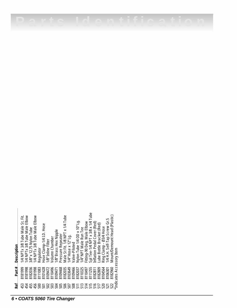
453
8181
999
1/4
NPT
x 3/
8 Tu
be M
ale
St. F
it.45
481
8199
81/
4 N
PTx
3/8
Tube
Mal
e El
bow
455
8182
036
3/8"
x 1
2.75
Nyl
on T
ube
456
8181
998
1/4
NPT
x 3/
8 Tu
be M
ale
Elbo
w50
081
1108
3Re
gula
tor
501
8101
428
Hose
Cla
mp-
1/4
I.D. H
ose
502
8109
472
1/8"
Inlin
e Fi
lter
503
8110
496
Volu
mn
Cham
ber
504
8109
471
1/8"
Bra
ss H
ex N
ippl
e50
581
0946
8Pr
essu
re R
epea
ter
506
8182
035
Mal
e St
Fit.
1/8
NPT
x 1
/4 T
ube
507
8103
649
1/4"
Hos
e x
12" L
g.50
881
0946
6Va
lve-
Pilo
ted
511
8182
037
Nyl
on T
ube
1/4
OD x
10"
Lg.
513
8110
325
1/4"
NPT
Mal
e Ru
n Te
e51
481
1049
7Fi
tting
-90
Deg.
Mal
e El
bow
515
8111
255
Spl T
ee-1
/4 N
PT x
3/8
x 1
/4 T
ube
516
8182
811
Infla
tion
Peda
l Cov
er (R
ed)
517
8182
809
Lube
Bot
tle B
rack
et (R
ed)
520
8104
564
Ring
Cla
mp
- Ø3/
4 Ho
se52
181
0630
11/
4 H.
H. S
elf-T
ap S
crew
Gr.5
522
8182
960
Mou
nt/D
emou
nt H
ead
(Pla
stic
)*I
ndic
ates
Acc
esso
ry It
em
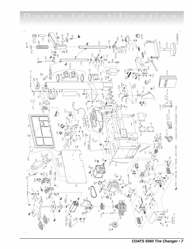
COATS 5060 Tire Changer • 7
Parts Identification
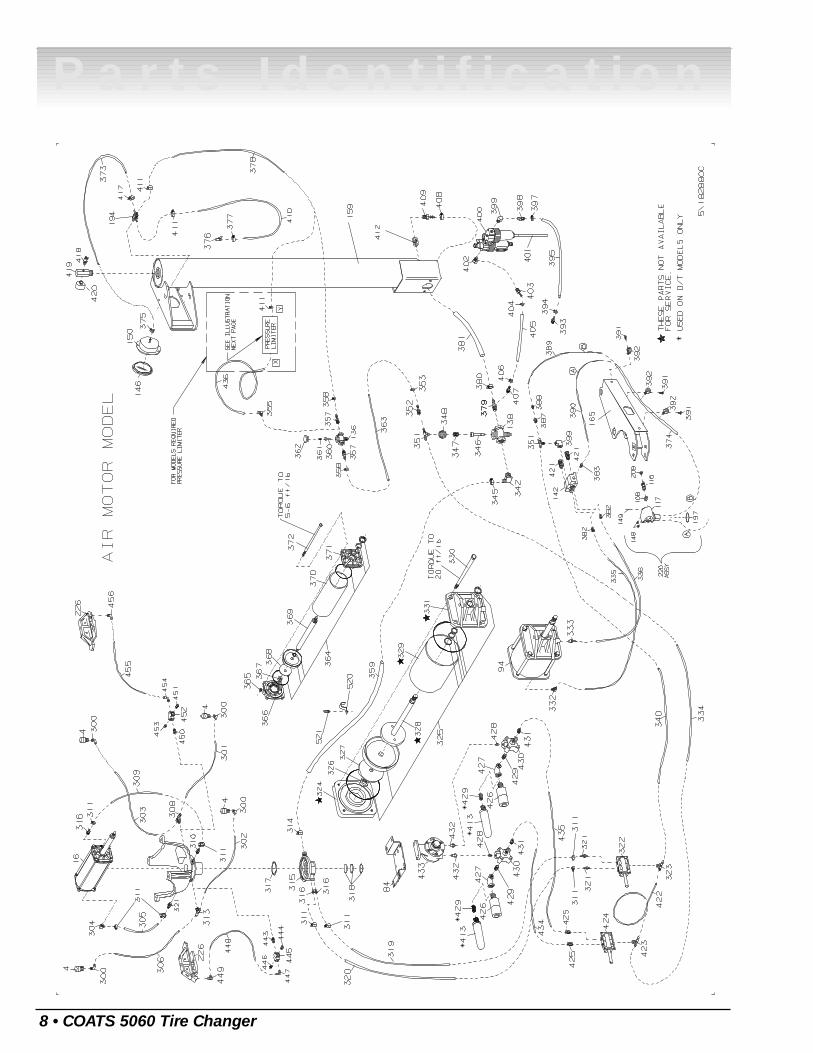
8 • COATS 5060 Tire Changer
Parts Identification
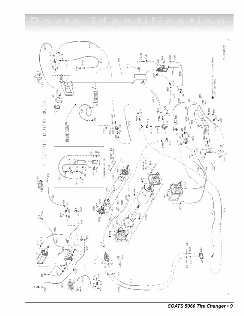
COATS 5060 Tire Changer • 9
Parts Identification
10 • COATS 5060 Tire Changer
Parts Identification

Notes
COATS 5060 Tire Changer • 11
Parts Identification
8182882 15 02/98 © Copyright 1995 Hennessy Industries and COATS All Rights Reserved Printed in USA
Rim Clamp® Tire ChangerAll-Air Unit Compressed Air Requirements
COATS® Rim Clamp® tire changers that are powered entirely by air (no electric motor) require a single com-pressed air power source. Refer to the table below for exact specifications.
Tire Changer Model Compressor Size Capable of
5030A 5HP 5 SCFM at 150 PSI
5050A 5HP 14-15 SCFM at 150 PSI
5060A 5HP 14-15 SCFM at 150 PSI
Oiler and Water Separator Maintenance
The oiler and water separator (on units so equipped) require weekly service. Oil and water levels (indicatedon the level gauge on the side of each bowl) should be checked regularly
1. Drain the water from the separator by unscrewing the petcock on the bottom of the bowl. Allow waterto drain and tighten petcock securely by hand.
2. Add oil to the oiler if the fluid level is more than 1/4" from the top of the gauge. Remove the filler plugin the top of the oiler, and add SAE 10W non-detergent oil or an air tool oil to bring the level up to 1/4" fromthe top of the gauge. Replace the filler plug and clean up any spilled oil.
3. Adjust the oil flow by pulling the red flow adjustment ring up and turning it to increase or decrease theflow. Push the ring down to lock. Watch the formation of oil drops in the see-through oil chamber. Continuallycycle the bead loosener through full strokes and count the drops during the cycles. The delivery of oil to theair line should be about 1 drop per 10 cylinder cycles. Adjust the flow as required.
Note: Some older units may use an adjustment screw on top of the oiler instead of the red ring and see-through chamber. To adjust these units, turn the screw fully clockwise to stop the flow, then turn it backcounterclockwise 1/4 turn.
Transmission Lubrication
Check the fluid level in the tabletop transmission with the oil check dipstick. If fluid shows on the dipstick,it is properly filled. If no fluid is present on the dipstick, add a high quality SAE 80/90 gear lubricant. Add lubri-cant and check the level. Stop adding lubricant when it shows on the dipstick.
Air Gauge Check and Recalibration
1. Inflate a standard 15" passenger car tire/wheel assembly to 32 PSI. Use a high quality stick-type pres-sure gauge to verify the pressure. Attach the tire changer's inflation hose to the valve stem and check thepressure reading on the air gauge. If it does not read 32 PSI, recalibrate the gauge.
2. Remove the screw-on lens. Loosen the 2 screws on the face of the gauge. Loosen them just enoughso that the gauge face moves. Do not remove the screws.
3. Rotate the gauge face until the 32 PSI mark is aligned with the gauge needle. Tighten the 2 screws andreplace the lens.
Danger, Warning, Caution, and Instructional Decals
Always make the cleaning of these important decals a part of your regular maintenance routine. If they aredamaged or illegible, replace them immediately. Your safety, and the safety of others is involved!