51n coordination with fuse
TRANSCRIPT

Ground Overcurrent Coordination for Radial Systems with Fuses
T Ernst page 1 2/7/05
Ground faults on radial distribution systems often involve significant amounts of fault resistance. Per-phase protection, such as fuses and single-phase reclosers, has limited capability to detect high-resistance faults as their pick-up must be set above load. For this reason, a ground overcurrent relay is commonly used in conjunction with 2 or 3 phase relays. The ground relay operates on 3I0 and is only subject to the unbalanced portion of the feeder load (typically 20 – 25% of the phase loading). Two methods for coordinating the ground and phase overcurrent relays with down-stream fuses are commonly used.
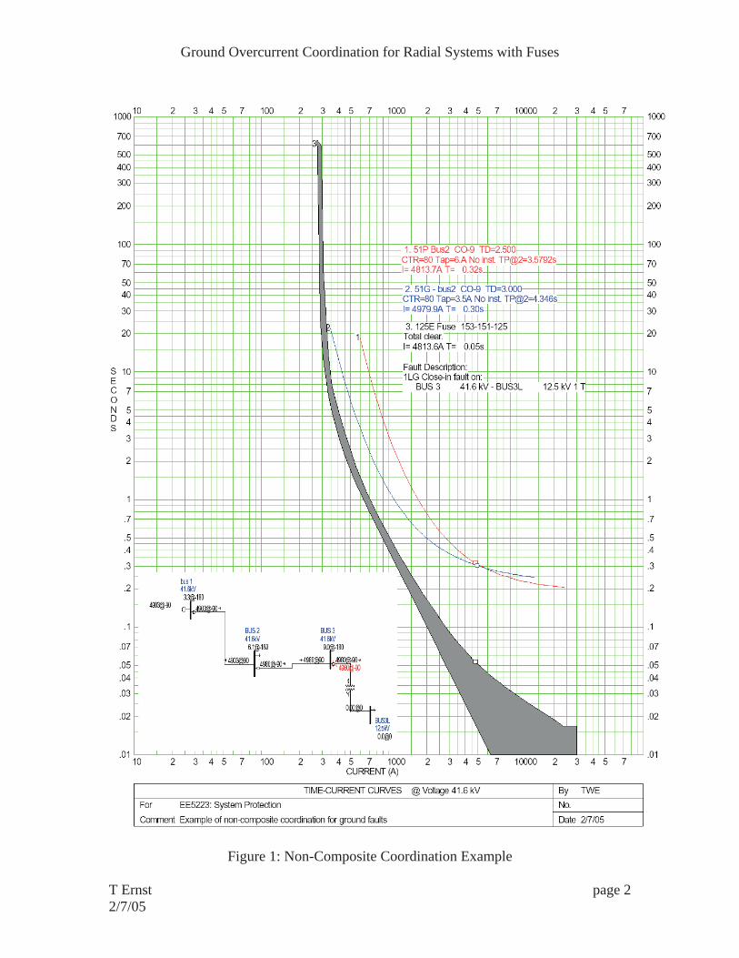
The first method adjusts the time dial for both the ground and phase relays to operate one coordination delay slower than the fuse for bolted faults (see figure 1). The pick-up of the phase overcurrent relay must be set above full load -- 480 amps in this example. The pick-up of the ground relay is set as low as possible but does not cross the fuse curve -- 280 amps in this case. This method works with either 2 or 3 phase relays.
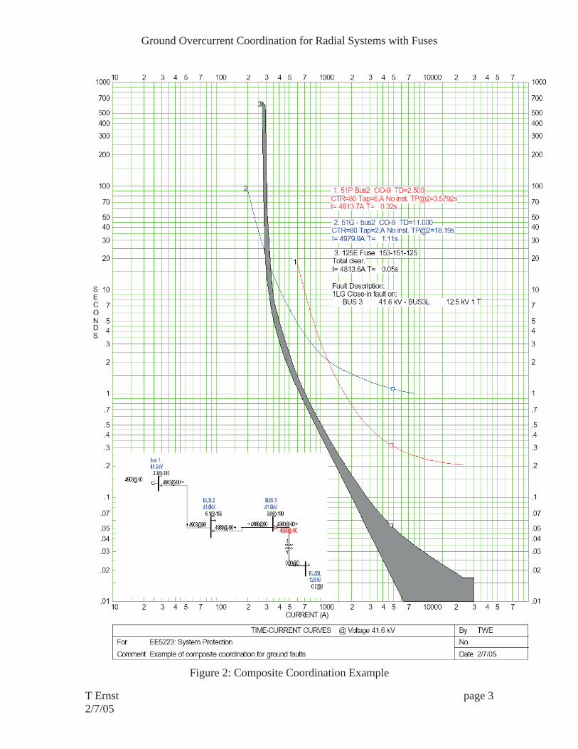
The second method uses the phase relay for tripping bolted ground faults and the ground relay only operates for low-level (high-resistance) ground faults (see figure 2). This system is known as the composite method since the effective ground tripping curve is a composite of the ground and phase relay curves. The pick-up and time dial of the phase overcurrent relay is set the same as in the first case -- 480 amps in this example. The time dial of the ground relay is set very slow (11 in this example) and the pick-up of the ground relay is set to allow the 51G curve to cross the fuse curve at a point well below any bolted 1LG faults -- 160 amps in this case. This method requires 3 phase relays.
Both methods are in common use however the composite method provides increased sensitivity to detect high-resistance faults.
Ground Overcurrent Coordination for Radial Systems with Fuses
T Ernst page 2 2/7/05
Figure 1: Non-Composite Coordination Example
Ground Overcurrent Coordination for Radial Systems with Fuses
T Ernst page 3 2/7/05
Figure 2: Composite Coordination Example