5701 5705.output
TRANSCRIPT
* GB786109 (A)
Description: GB786109 (A) ? 1957-11-13
Amino derivatives of acrylic and methacrylic acids
Description of GB786109 (A) Translate this text into Tooltip
[75][(1)__Select language] Translate this text into
The EPO does not accept any responsibility for the accuracy of data and information originating from other authorities than the EPO; in particular, the EPO does not guarantee that they are complete, up-to-date or fit for specific purposes.
PATENT SPECIFICATION 786,109 Date of Application and filing Complete Specification July 18, 1955. No 20730/55. Application made in United States of America on July 20, 1954. Complete Specification Published Nov 13, 1957. Index at Acceptance:-Classes 2 ( 3), C 2 (B 18:B 38: D 45); a nd 2 ( 6), P 8 A, P 8 D( 2 A: 2 B 2: 3 A: 3 B: 4 5), POK( 4: 7: 8: 9:11), P 8 P 1 (B: C:D: El: E 2: E 3 E 4: E 5: F), P 8 P( 2 A 5: 3: 5: 6 A). International Classification: -CO 7 c C 08 f. COMPLETE SPECIFICATION Amino Derivatives of Acrylic and Methacrylic Acids We, ROHM & HAAS COMPANY, a corporation organized under the laws of the State of Delaware, United States of America, of 222 West Washington Square, Philadelphia 5, Pennsylvania, United States of America, do herebv declare the invention, for which we pray that a patent may be granted to us, and the method by which it is to be performed, to be particularly described in and bv the following statement:This invention is concerned with amino derivatives of acrylic and methacrylic acids. In brief, this invention provides new amino derivatives of acrylic and
methacrylic acids and which are of the formula:CH 2 =C-COO-A-NR R CN where R is a hydrogen or methyl, R' is an alkyl, cycloalkvl, aryl or aralkyl group, and A is a C:-CQ alkylene group having at least two carbon atoms between OX Jgen and nitrogen. The invention also provides polymers of such compounds and copolymers thereof with other copolymerizable ethylenically unsaturated compounds. A method of preparing one group of the new monomeric compounds comprises reacting, in the presence of an acceptor for hydrogen halide, cyanogen chloride or bromide with a compound of the formula GH=G{R)COCO, 112-NHR', where the group' C I 1, provides at least two carbon atoms between the oxygen and nitrogen atom, N being an intezer of 2 or 3, and R' is a C,-C-, tertiary alkyl group As acceptor there may be used an alkaline reagent such as sodium hydroxide, potassium hydroxide, calcium hydroxide, sodium carbonate potassium carbonate, sodium bicarbonate or potssium bicarbonate The reaction is usually performed between 00 and 750 C, Preferably in the presence of a solvent, including water, naphtha, benzene toluene, xylene, chlorinated hydrocarbon, or the like The product can be collected as a residue and is often lPrice 3 s 6 d l distillable for the purposes of purification. The starting tert-allkylaminoalkyl acrylates and methacrylates employed in the above reaction are available by reacting a suitable tert-alkylaminoalkanol, i e a compound of the formula R'NH Cn HO 1 OH, and a CQ-C 4 alkyl acrylate or methacrylate in the presence of a transesterification catalyst While usually the reaction of a secondary amine with an acrylate or methacrvlate leads to amides, it has been unexpectedly discovered that when a tert-alkyl group is present on a secondary amino group, esters are formed rather than amides, as shown in the specification of our copending Aprlication No 20731/55 (Serial No 776,503) As there described, a tert-alkylaminoalkanol as defined above is mixed with a C,-Cl alkyl acrylate or methacrylate along with a catalyst. The usual catalyst is sodium metal sodium methoxide, sodium ethoxide, sodium butoxide potassium ethoxide, potassium butoxide, or other alkali metal or alcoholate thereof, aluminum ethoxide or iso Dro Doxide or a tetraalkyl titanate, such as tetraisopropyl titarate or tetrabutyl titanate The reaction mixture is heated between 60 and 160 ' C with evolution of lower alkanol and distillation of remaining alkyl acrylate or methacrylate There is obtained as a residue the desired tert-alkylaminoalkyl acrylates or methacrylate, which may usually be purified by distillation. In a typical preparation according to said copending application, there are mixed 58 5 parts by weight of tert-butylaminoethanoc (made
by reacting one mole of tert-butylamine with one mole of ethylene oxide in the presence of water and/or an aqueous acid as catalyst) 86 parts by weight of methyl acrylate, 7 parts by weight of di-fl-naphthol, and one part by weight of aluminum isopropoxide The mixture is heated under reflux and vapors are then taken off through a short column with a partial talke-off head A methanol-methyl acrylate azeotrope is taken off at 65 -78 C. followed by a fraction of methyl acrylate After P 5 L 1 _ 1 1 -2a forerun of not quite pure product, there is obtained a fraction of essentially pure tertbutylaminoethyl acrylate at 90 -1 ( O C /13 mm In a similar way, a mixture of 86 5 parts by weight of I-2,4,4 trimethyl-2-pentylaminoethanol, 150 parts by weight of methyl methacrylate, 7 parts by weight of di-f-naphthol, and one part by weight of aluminum isopropoxide is heated and distillate taken off this being at first methanol and then methyl methacrylate The product distils at 125 -1320 C./9 mm and corresponds closely in composition to N-tert-octylaminoethyl methacrylate Instead of using methyl methacrylate in the above preparations, other alkyl esters, such as ethyl acrylate or methacrylate, propyl acrylate or methacrylate or butyl acrylate or methacrylate, may also be used Also, other tert-alkylaminoalkanols may be used, e g those compounds in which the tertiary group is any of the tertiary forms of butyl, octyl, nonyl or dodecyl groups Alternatively, the tert-allkylaminoalkanol starting material may be derived from a mixture of tert-alkylamines such as commercially available mixtures of Cl-DC, or C,,,-C 24 tert-alkylamines. As an alternative method for preparing the monomeric amino derivatives of the invention, there may be used as starting material a compound of the formula:RR CII,=CCOO-A-N R R 2 where R and A are as defined in the early part of this specification and R' is an alkyl aralkyl, cycloalkyl or aryl group, and R 2 is a C-C, alkyl or a benzyl group, and is more easily removed from the amino group than RW A compound of this formula is reacted by addition between O and 750 C with cyanogen chloride or bromide, apparently to form a quaternary compound, which when heated to 50 ' to 1500 C decomposes with loss of R 2 G 1 or R 2 Br to give the cyanamide RW-N-A-OOCC=CH 2 I I CN R The advantage of this method is that it permits the use of a variety of N-substitutents over a wide range of sizes and permits use of various alkylene groups as the group A. Details of typical preparations are shown in the following illustrative examples, wherein all parts are by weight:EXAMPLE 1 To a mixture of 146 parts of N-tert-butylaminoethyl methacrylate, 66 parts of anhydrous potassium carbonate, and 500 parts of water is added with stirring under reflie: 51 tarts of cyanogen chloride as a
gas at 95-13 C. After one hour at 13 -20 C and two hours at 30 C, the upper layer is separated, the aqueous layer extracted with benzene, and the total organic layers stripped under water vacuum to remove benzene After addition of 2 parts of di-beta-naphthol, the cyano derivative is distilled to yield 143 parts of colorless liquid boiling at 136 -138 C/2 7 mm. It contains by analysis 13 4 % of nitrogen and is N-cyano-N-tert-butylaminoethyl methacrylate, for which the theoretical nitrogen content is 13 3 %. EXAMPLE 2 In the same manner as described for the methacrylate, from 174 parts of tert-butylaminoethyl acrylate and 70 parts of anhydrous potassium carbonate in 650 parts of water, treated with 61 5 parts of cyanogen chloride dissolved in 200 parts of toluene at 8 -11 C., there is obtained 60 parts of N-cyano-Ntert-butylaminoethyl acrylate distilling at 162 -172 C /28 mm It was fiount 1 to contain 13 8 % 1 of nitrogen and is N-c T-ano-Ntert-butylaminoethyl acrylate. EXAMPLE 3 In the same way there were reacted 227 parts of N-tert-octylaminoethyl acrylate and 61.5 parts of cyanogen chloride in tohlene in the presence of 70 parts of potassium carbon 85 ate in water The product, N-cyano-N-tertoctylaminoethyl acrylate, is obtained as a fraction distilling at 187 -197 ' C /30 mm. In the same way there are reacted N-tertalkylaminoethyl acrylates or methacrylates 90 having up to 24 carbon atoms in the tert-alkyl portion In every case a -CN group becomes attached to the amino nitrogen to give the corresponding N-cyano derivative. The above described alternative method 95 provides a means of preparing the monomeric compounds of the invention in great variety so far as concerns the identity of the A and R' groups in the formula given earlier The R' group may vary from methyl to octadecyl, for 100 example The linking alkylene group A may have tw Uo, three, or mnore carbons between nitrogen and oxygen Thus, the starting acrylate or methacrylate may have as the esterifying group such substituents as dimethylaminoi 105 ethyl, dimethlylaniinopropyl, diethylamnio ethyl diethylaminopropyl, octvlmethxrlaminopropyl, dedecylmetviylaminonropyl, octadecylmethylaminopropyl, or dodecylethylaminopropyl As already indicated, the N-substitu 110 ents noeed not be limited to alkyl, and cycloalkyl and ara Lklyl groups may be present, such as cyclohexyl and bcnzyl This alternative method is described in more detail in the following illustrative examnles wherein parts 115 shown are by weight. EXAMPLE 4
A solution of 47 parts of dimethylaminoethyl methacrylate in 110 parts of benzene is cooled to 40 C, and a solution of 18 5 parts 120 of cyanogen chloride in 42 parts of benzene 786,109 or more is usually sufficient, based on the 65 weight of monomer or monomers. For preparing many copolymers there may likewise be used the peroxidic free radical catalysts Typical organic peroxides are benzoyl peroxide, acetyl peroxide, caproyl peroxide, 70 lauroyl peroxide, methyl ethyl ketone peroxide, butyl perbenzoate, tert-butyl hydroperoxide, or cumene hydroperoxide. For emulsion or suspension polymerization there may be used ammonium persulfate, 75 sodium persulfate, potassium persulfate, or hydrogen peroxide, best in a redox system containing a reducing substance such as sodium sulfite, bisulfite, metabisulfite, or hydrosulfite, with or without a metal as 80 activator. In a typical polymerization there are placed in a polymerization cell 5 parts of N-cyano-Ntert-butylaminoethyl methacrylate and 0 05 part of dimethyl azodiisobutyrate The cell is 85 blanketed with nitrogen and heated at 700 C. for seven hours A hard glass-like poylmnresults Analysis shows the presence of 13 2 % of nitrogen (theory 13 3 %) In the above preparation and all those subsequently given parts 90 are by weight. In the same way 5 parts of N-cyano-Ntert-octylaminoethyl acrylate and 0 05 part of dimethyl azodiisobutyrate are mixed and heated under nitrogen at 700 C for 16 hours A 95 tough polymer results Likewise, 5 parts of Ncyano N tert-alkylaminoethyl methacrylate having N-tert-alkyl groups of 12 to 15 carbon atoms is heated with 0 05 part of dimethyl azodiisobutyrate for 12 hours at 70 -750 C 100 A tough gum is formed This is useful as a component of coating compositions. Copolymers of the N-cyano-N-alkylaminoalkyl acrylates or methacrylates with other polymcrizable ethylenically unsaturated com 105 pounds are prepared according to usual methods When the above acrylates or methacrylates -provide the major proportion azo initiators are of first choice When they are used in minor proportions, either azo or per 110 oxidic catalyst may be effectively used Copolymers may be prepared from one or more of the above acrylates-or methacrylates and one or more other polymerizable unsaturated compound, such as alkyl acrylate 1 5 or methacrylatc, including methyl acrylare, methyl methacrylate, butyl acrylate, hexyl methacrylate, octyl acrylate, dodecyl methacrylate, acrylamide, N-alkyl acrylamides, methacrylamide, acrylonitrile, methacrylo 120 nitrile, dimethyl itaconate, diethyl itaconate, diethyl fumarate, dimethyl maleate, styrene, vinyltoluene, p-chlorostyrene, vinylpyridine, vinylpyrrolidone, vinyl acetate, vinyl propionate, allyl acetate N-allyl acetamide, methoxy 125 ethyl acrylate, dimethylaminoethyl methacrylate tetrahydrofurfuryl
methacrylate, benzyl acrylate, cyclohexyl methacrylate or oleyl acrylate Polyvinylidene compounds can also be added at 6 -12 C over a period of one hour. The mixture is then stirred for one hour at -20 C, and 2 5 hours at 40 '-45 C. It is then warmed to 70 C for one hour and cooled to room temperature One hundred twenty parts of ether is added and the mixture filtered The filtrate is stripped under water vacuum To the residue is added 2 parts of di-beta-naphthol On distillation there is obtained 29 6 parts of clear light-yellow cyanamido-ester, distilling at 126 -1320 C /2 9 mm It is found to contain 16 7 % of nitrogen and is N-cyano-N-methylaminoethyl methacrylate. IS In place of the above used N,N-dimethylaminoethyl methacrylate there are used 53 parts of NN-dimethylaminopropyl methacrylate The reaction is carried out in the same way to yield 24 parts of beta-(N-cyano-Nmethylamino)propyl methacrylate distilled at -135 C /3 mm. In the same way 45 parts of beta-(dimethylamino)ethyl acrylate is subbtituted in the above reaction system The product is N-cyano-Nmethylaminoethyl acrylate, distilling at 123 129 C /3 mm. EXAMPLE 5 There are mixed 50 parts of N-dodecyl-Nmethylaminoethyl methacrylate and 100 Darts of toluene The mixture is cooled below 100 C and treated with 10 parts of cyanogen chloride in 20 parts of toluene This mixture is stirred for six hours with the temperature thereof being carried to about 80 C The reaction mixture is cooled and filtered The filtrate is evaporated to yield a residue which corresponds in composition to N-cyano-Ndodecylaminoethyl methacrylate. The N-cyano-N-alkylaminoalkyl acrylates and methacrylates are useful as chemical intermediates They react with alcohols to give isoureas, which are useful in providing a new kind of polymer useful as agents for improving the strength of paper They react with mercaptans to give isothioureas of interest in the field of insecticides With arylamine salts they give guanidine salts which give useful water-soluble resins An important use of the monomers of the invention is to provide valuable polymers and copolymers For polymerization there are desirably used one or more of the azo free radical catalysts These contain an-N=Ngroup attached to aliphatic carbon atoms, at least one of which is tertiary Typical examples of these polymerization initiators are azodiisobutyronitrile, azobis(alpha-gamma-dimethylvaleronitrile), azobis(alpha methylbutyro nitrile), azediisobutyramide, dimethyl, diethyl, or dibutyl azodiisobutyrate, or dimethyl, diethyl, or dibutyl azobis(methylvalerate) These and other similar azo compounds serve as
initiators for both homopolymerization and copolymerization An amount of 0 010/ to 2 % 786,109 used, these giving cross-linked copolymers, such as allyl acrylate, vinyloxyethyl acrylate, vinyloxypropyl methacrylate, ethylene diacrylate, ethylene dimethacrylate, divinylbznzene, or diallyl phthalate. A mixture is prepared from 9 5 parts of acrylonitrile, 3 4 parts of N-methyl-N-cvanoaminoethyl methacrylate, and 0 1 part of azodiisobutyronitrile in two parts of toluene This mixture is slowly charged to a reaction vessel equipped with stirrer and heated by an oil bath at 110 C The vessel is continuously blanketed with nitrogen Additions of catalyst in toluene are made at 3 1 hours ( 0 02 part), 4 5 hours ( 0 009 part), and at 6 1 hours ( 0 005 part) Heating is continued for 20 hours Toluene is added to give a 50 % solution of copolymer A 30 % solution has a viscosity of 49 cs at 1000 F The copolymer forms tough hard films. There are mixed 25 parts of N-cyano-Ntert-butylaminoethyl methacrylate, 75 narts of methyl methacrylate, 0 13 part of azeoiisobutyronitrlie, and 5 parts of toluene Under a nitrogen blanket this mixture is slowly added to a polymerization vessel equipped with stirrer and heated with an oil bath at 100 C During the course of polymerization small amounts of catalyst are added-0 05 part at 3 5 hours. 0 02 part at 4 5 hours and 0 01 part at 6 0 hours After ten hours of heating enough toluene is added to bring the total weight to parts The product is a solution of 44 % of copolymer It forms hard films and coatings. There are mixed 10 parts of N-cyano-Ntertdodecylaminoethyl acrylate, 10 parts of lauryl-myristyl methacrylate (these alkyl groups being those obtained from a fractionated lauryl alcohol) and 0 03 part of ditnethyl azodiisobutyrate in two parts of toluene The mixture is slowly charged to a polymerization vessel maintained under a blanket of nitrogen, equipped with stirrer, and heated wenith an oil bath held between 110 and 115 ' C As above, small additions of catalyst are made in toluene-0 01 part at 3 5 hours, 0 01 part at 4.5 hours, O 01 part at 5 5 hours, and 0 01 part at 6 5 hours Heating is continued until 16 hours have elapsed Toluene is then added to bring the total weight to 40 Parts There is formed a 42 % solution of the copolymer It has a viscosity of 169 cs at 1000 F The copolymer is a useful additive for lubricating oils, improving the viscosity-index and supplying low temperature dispersing action.
* Sitemap * Accessibility * Legal notice
* Terms of use * Last updated: 08.04.2015 * Worldwide Database * 5.8.23.4; 93p
* GB786110 (A)
Description: GB786110 (A) ? 1957-11-13
Improvements relating to the running-in of internal combustion engines
Description of GB786110 (A)
PATENT SPECIFICATION 1 In'entor: WITOLD MIGURS'KI 7 i Date of Application and filing Complete Specification: July 20, 1955. No 2 1011/55. Complete Specification Published: Nov 13, 1957. Index at acceptance:-Class 7 ( 2), B 2 L 3 A 4. International Classification:-FO 2 b. COMPLETE SPECIFICATION Improvements' relating to the Running-in of Internal Combustion Engines We, JENOGRAPH LIMITED, a British Company, of 13/17 Rathbone Street, London, W 1, do hereby declare the invention, for which we pray that a patent may 'be granted to us, and the method 'by which it is to be performed, to be particularly described in and by the following statement: - This invention relates to the running-in of internal combustion engines, particularly diesel engines. It is known to use suspensions of graphite in oil, sometimes called colloidial graphite, in order to accelerate the running-in of engines or mechanical joints of all kinds, the contacting surfaces being smeared with the colloidal graphite or being lubricated with suitable oils or being both smeared and lubricated Although this reduces the running-in time, it is still for engines of several hours duration, the graphite having to be supplied to all the surfaces in friction to form a so called graphoid surface by filling up depressions in the contacting surfaces resulting from roughness in the metal It usually takes about two to six hours to produce a satisfactory result;
however, the present invention permits this time to be reduced to about fifteen minutes after which an engine can be run at its full power without there being any danger of the metal seizing or of direct metal to metal contact between pistons, piston rings and cylinder walls. According to the present invention, the running-in of internal combustion engines is accelerated by the introduction through an air inlet pipe of the engine of an intimate mixture of a metallic salt or salts and dry powdered graphite The mixture can be introduced by means of a distributor comprising means for fitting the distributor near the entrance of an air inlet pipe of the engine, a reservoir for the mixture having an outlet through which the mixture can be supplied to the air inlet pipe, means for controlling the flow of the mixture through the outlet, and means adjacent the outlet for accelerating and causing lPrice 3 s 6 di 86 A 110 turbulence in the mixture issuing from the outlet. The graphite is preferably natural, crystalline, lamellar, cleavable graphite containing about 99 % carbon and leaving no abrasive 50 residues for combustion It is finely ground to the size made necessary by the roughness of the metal surfaces to be treated, e g to a size at the largest dimension of about 4 to '7 microns for normally worked metal, 2 to 4 55 microns for normally finished metal, 1 micron for industrially over-finished, i e bench runin, metal, and, to smaller than 1 micron for polished surfaces A metallic salt or salts appropriate to the lubricant normally used are 60 added to the powdered graphite, these salts being ground to the same particle size as the graphite and intimately mixed with it These salts are advantageously oleates, naphthenates or phosphates of sodium, potassium, tin or 65 lead and are used either separately or in mixtures. As the mixture is introduced in a dry powdered form through the air inlet pipe of the engine instead of 'being introduced into the 70 crank case by means: of lubricating oils, it is immediately brought into contact with the surfaces to be protected, e g the pistons, piston rings or cylinder walls. The quantity of powder used varies accord 75 ing to the cylinder capacity of the engine concerned For example, an engine with a cylinder capacity of 7 litres required 42 grams of powder or 6 grams per litre cylinder capacity This quantity of powder was assimilated 80 in about 12: minutes, i e at a rate of about 31 grams per minute. The accompanying diagrammatic drawing is a sectional elevation of a distributor for introducing a powder comprising an intimate mix 85 ture of a metallic salt or salts and dry powdered graphite to an air inlet pipe of an internal combustion engine.
The apparatus illustrated in the drawing can be made of any suitable material such 90 as metal, plastic or glass It comprises a reservoir for the powder having an upper cylindrical part 1, a lower conical part 2 and a cylindrical bottom outlet 3 The top of the reservoir is closed by a cover 4 from the centre of which a valve rod 5 extends axially through the reservoir into the outlet 3 This rod 5 has a knob 6 at the top so that the rod can be moved inwards or outwards of the reservoir to adjust the position of the bottom of the rod with respect to the outlet 3 (and therefore the rate of flow of powder from the reservoir) The setting of the valve rod 5 is preferably such that the powder will be discharged from the reservoir in about twelve minutes The lower portion 2, 3 of the reservoir is surrounded by a chamber 7 having a conical lower part and an opening 8 co-axial with the outlet 3,; when the distributor is fitted to an air inlet pipe of an internal combustion engine the chamber 17 will accelerate and cause turbulence in the powder issuing from the outlet 3 A flange 9 is provided for fixing the distributor to the air inlet pipe near its entrance.
* Sitemap * Accessibility * Legal notice * Terms of use * Last updated: 08.04.2015 * Worldwide Database * 5.8.23.4; 93p
* GB786111 (A)
Description: GB786111 (A) ? 1957-11-13
Dynamic microphone having a preferential response in one direction
Description of GB786111 (A)
A high quality text as facsimile in your desired language may be available amongst the following family members:
US2865464 (A) US2865464 (A) less Translate this text into Tooltip
[79][(1)__Select language] Translate this text into
The EPO does not accept any responsibility for the accuracy of data and information originating from other authorities than the EPO; in particular, the EPO does not guarantee that they are complete, up-to-date or fit for specific purposes.
PATENT SPECIFICATION 786,111 Date of Application and filing Complete Specification Aug 3, 1955. No 22249/55. Application made in Austria on Aug 7, 1954. Application made in Austria on Dec 1, 1954. Complete Specification Published Nov 13, 1957. Index at Acceptance: -Class 40 ( 4), J 1 (A: K), P 5. International Classification: -Gl Ok HO 4 m. COMPLETE SPECIFICATION Dynamic Microphone having a Preferential Response in one Direction We, AKUSTISCHE U KINO-GERATE GES M B H, of Nobilegasse, 50, Vienna XV, Austria, an Austrian Company, do hereby declare the invention, for which we pray that a patent may be granted to us, and the method by which it is to be performed, to be particularly described in and by the following statement:This invention relates to a dynamic microphone of the type which is responsive in a certain frequency range and has a preferential response in one direction and which comprises a single diaphragm and means defining a low air chamber behind the rear face of said diaphragm. In this specification the term " low air chamber " refers to a chamber defined between the diaphragm and a mechanical confining means which is disposed a small distance behind the diaphragm and extends substantially parallel thereto The distance between this confining means and the diaphragm should be sufficient, however, to prevent the diaphragm from contacting the confining means even under high sound pressure or climatic or temperature influences In practice this distance may vary between 0 3 mm and 0 8 mm. It is known to design dynamic microphones, particularly of the moving-coil type, for a preferential response in one direction In one known construction the diaphragm is directly exposed to the sound field on one side whereas the other side is acoustically influenced through an acoustic device rotating the phase of the sound waves, and frictional resistances in conjunction with a cavity. In another known embodiment the rear side of the diaphragm is coupled
through a very low air chamber (to air plugs contained in narrow tubes, whose length is less than half, suitably a quarter of the wavelength of the highest frequency to be transmitted and which lead directly into the open. In this specification the term "air plug" refers to a body of air which is contained in a tube and has a cross-section which is much lPdce 3 s 6 d 1 smaller in diameter than the length of said body to provide for a velocity of the air in the tube which is higher than the velocity of the diaphragm Moreover, the cross-section of the 50 air plug is much smaller than the area of the diaphragm to provide for a strong mass action of the plug. It has been found that in the former case it is difficult to maintain the acoustic conditions 55 required for a preferential response on one side throughout the transmitted frequency range and that in the second case the driving force due to the pressure gradient is small owing to the small length of the air plugs so that the 60 microphone has an increased sensitivity to shock because the small driving force requires the diaphragm gripping means to have a relatively low natural frequency. It is an object of the invention to provide 65 a microphone of the type described in which the aforesaid disadvantages are avoided. According to the invention the microphone comprises means defining a cavity whose length is substantially larger than the shortest wave 70 length of said frequency range and which have at least one opening connecting said cavity to said low air chamber and at least one additional opening connecting said cavity directly to the sound field surrounding the microphone, said 75 cavity having such an effective cross-sectional area that said diaphragm forms with respect to said cavity a terminating impedance which cor responds substantially to the characteristic impedance of a cavity of said effective cross 80 sectional area and of infinite length, means defining a second air chamber, and frictional resistance means connecting said second air chamber to said low air chamber. In this specification the term " effective 85 cross-sectional area of a cavity " refers to the cross-sectional area of the opening or the total cross-sectional area of the openings which connect said cavity to the low air chamber behind the diaphragm The term " length of a cavity " 90 refers to the length of the sound transmitting path it provides between said low air chainme ber and the opening which connects the cavity directly to the sound field surrounding the microphone or, where said cavity is directly connected by several openings to the sound field surrounding the microphone, to the length of the longest of the sound transmitting lines provided by said cavity between said low air chamber and said several openings.

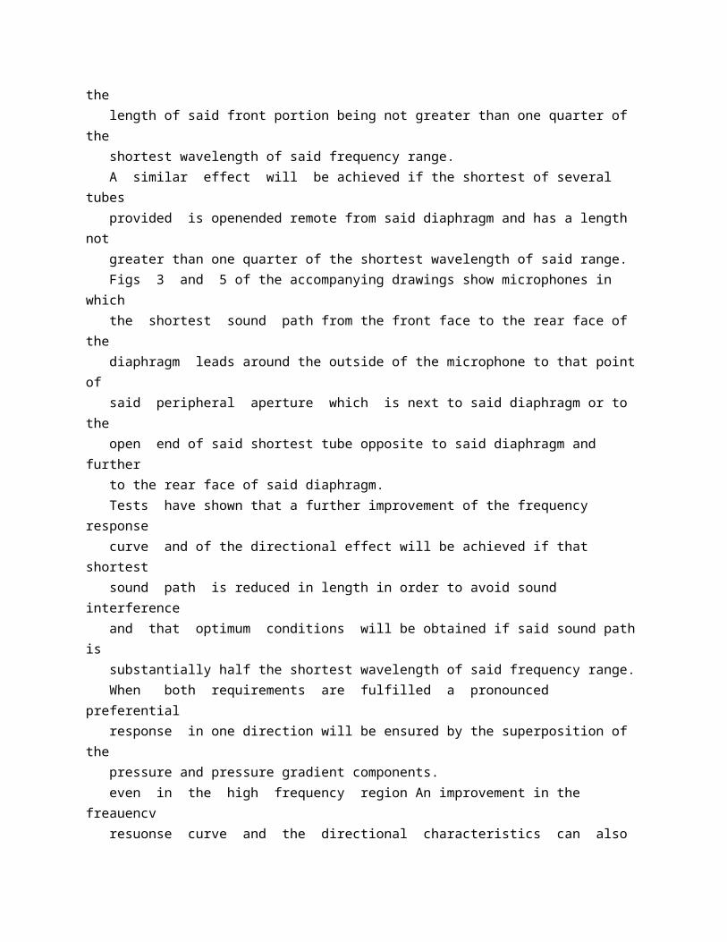
Said means defining said cavity may comprise a tube and said low air chamber may have connected thereto at least one additional tube shorter than said first-mentioned one, all said tubes being stepped in length and equal or different in cross-sectional area to provide for a compensation of any crests and troughs in the frequency response curve of the microphone due to the formation of standing waves in said tubes. The means defining said cavity may comprise a peripheral wall formed with one or more openings consisting, e g, of substantially round holes or substantially elongated slots. The said openings may be distributed over the area of said wall and damping means may be provided in or on said opening or one or more of said openings. To avoid disturbing standing waves in the high frequency region the means defining said cavity may comprise a peripherally unapertured front portion next to said diaphragm and a rear portion remote from said diaphragm and formed with at least one peripheral aperture, the length of said front portion being not greater than one quarter of the shortest wavelength of said frequency range. A similar effect will be achieved if the shortest of several tubes provided is openended remote from said diaphragm and has a length not greater than one quarter of the shortest wavelength of said range. Figs 3 and 5 of the accompanying drawings show microphones in which the shortest sound path from the front face to the rear face of the diaphragm leads around the outside of the microphone to that point of said peripheral aperture which is next to said diaphragm or to the open end of said shortest tube opposite to said diaphragm and further to the rear face of said diaphragm. Tests have shown that a further improvement of the frequency response curve and of the directional effect will be achieved if that shortest sound path is reduced in length in order to avoid sound interference and that optimum conditions will be obtained if said sound path is substantially half the shortest wavelength of said frequency range. When both requirements are fulfilled a pronounced preferential response in one direction will be ensured by the superposition of the pressure and pressure gradient components. even in the high frequency region An improvement in the freauencv resuonse curve and the directional characteristics can also be achieved if only the length of the peripherally unapertured front portion of the means defining said cavity or the length of the shortest of a plurality of tubes of stepped length is dimensioned as stated above, even if the sound path is long (e.g due to a large baffle or diaphragm); in this case the directional effect in the high frequency region will be determined by the size of the diaphragm or
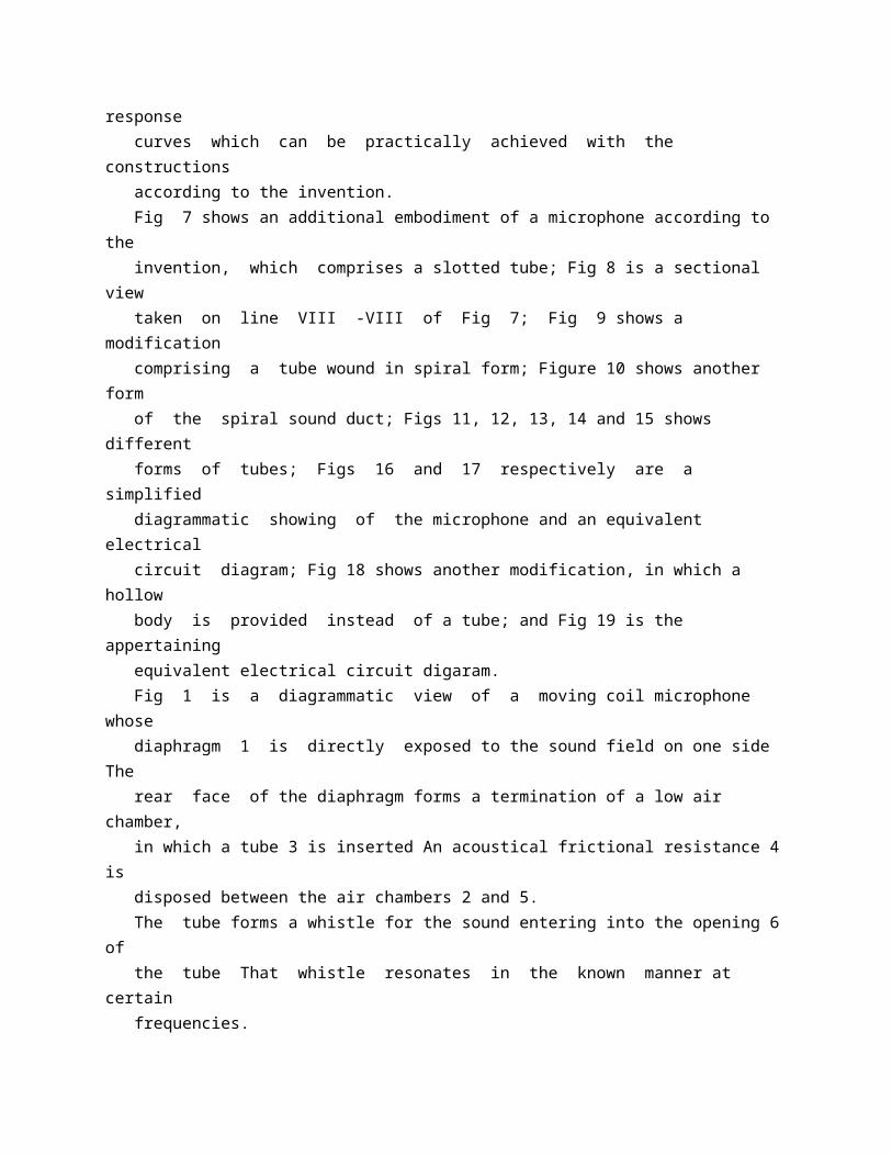
baffle. It is desirable if the cavity or any of the tubes communicating with the low air chamber behind the diaphragm are of winding configuration, e g of spiral form, in order to save space. Illustrative embodiments of the invention are shown in the accompanying drawings, in which:Fig 1 is a diagrammatic view of a movingcoil microphone according to the invention; Figs 2 a and 2 b respectively show the stand. ing wave of the fundamental frequency as formed when the tube is closed and open; Fig 3 is a diagrammatic sketch of a microphone having a cardicid directional characteristic and comprising two connected tubes; Fig 4 is the appertaining equivalent electric circuit diagram; Fig 5 is a microphone having a preferential response in one direction and formed with a longitudinal slot; Fig 6 shows frequency response curves which can be practically achieved with the constructions according to the invention. Fig 7 shows an additional embodiment of a microphone according to the invention, which comprises a slotted tube; Fig 8 is a sectional view taken on line VIII -VIII of Fig 7; Fig 9 shows a modification comprising a tube wound in spiral form; Figure 10 shows another form of the spiral sound duct; Figs 11, 12, 13, 14 and 15 shows different forms of tubes; Figs 16 and 17 respectively are a simplified diagrammatic showing of the microphone and an equivalent electrical circuit diagram; Fig 18 shows another modification, in which a hollow body is provided instead of a tube; and Fig 19 is the appertaining equivalent electrical circuit digaram. Fig 1 is a diagrammatic view of a moving coil microphone whose diaphragm 1 is directly exposed to the sound field on one side The rear face of the diaphragm forms a termination of a low air chamber, in which a tube 3 is inserted An acoustical frictional resistance 4 is disposed between the air chambers 2 and 5. The tube forms a whistle for the sound entering into the opening 6 of the tube That whistle resonates in the known manner at certain frequencies. When the tube is closed, as is shown in Fig 2 a, the fundamental wave produced, shown with a dash line, will have a wavelength oa ' 111 11; 786,111 coil under a constant sound pressure acting on he diaphragm 65 Fig 5 shows a microphone which has a preerential response in one direction and which contains a tube whose periphery is formed with a longitudinal slot S This gives rise to a simiar effects as where a plurality of parallel tubes 70 of different length are employed The diaphragm M and parts of the magnetic system Corm a low air chamber D,, from which the air can pass through the frictional resistance R into the chamber D The air chamber D, has 75 connected thereto the
tube M 1, which is formed with a longitudinal slot S A very uniform effect is provided by a suitable dimensioning of the slot and insertion of damping material 80 In Fig 6 the frequency response curves of a microphone having a tube 20 cm long are shown with dotted lines for a sound incidence at 0 deg and 180 deg The solid curve shows the frequency curve achievable with two tubes 85 of 20 cm and 10 cm length, respectively, also for a sound incidence at 0 deg and 180 deg. The graph shows how the frequency response curves are flattened by the combination of several tubes Instead of two tubes, any desired 90 number of them may be provided, with any desired stepping in length and with the same or different cross-sectional area. Fig 7 shows a microphone in which the shortest sound path from the front face to the 95 rear face of the diaphragm is reduced in length. The slot in the tube wall begins at 7 The tube is surrounded by a cylinder of felt or the like, which covers the slot and which may be tapered towards the free end of the tube Fig 8 100 shows the construction according to Fig 7 in a cross-sectional view. Fig 9 illustrates a modification of the invention, comprising a tube which is coiled to form a spiral and the acoustic impedance of which 105 has a similar effect on the diaphragm as that of the straight tube In this case the slot begins also at 7 Instead of the slot the tube may be formed with juxtaposed holes; in this case the hole next to the diaphragm is spaced from the 110 latter by a distance which corresponds to a quarter wavelength of the highest sound In front of the diaphragm a solid of revolution 8 may be arranged, which forms a flat air chamber between its curved front end face and the 115 diaphragm The conical body 9, which is held by arms 10, is concentrically disposed with respect to said solid of revolution Thus an annular funnel is formed, in a manner known per se which-may increase in cross-sectional 120 area as desired This construction provides for a flattening of the frequency response curve and an improvement of the directional characteristic in the high frequency region. Fig 10 shows another embodiment of the 125 sound duct or cavity of spiral configuration. The chamber 11 is defined by the hollow inner core member 111, which has on its cylindrical which is four times the tube length When c the tube is open, as shown in Fig 2 b, a stand t ing wave will be formed which has an antinode at the tube end; this means that its wave 1 length is twice the tube length All possible c termination arrangements lie between the a closed tube having a hard termination and the 1 open tube. If the tube is terminated by an impedance 1 which corresponds to the characteristic impedance of an infinitely long tube, no reflected wave
will occur The magnitude of this terminating impedance is z= 8 c f= 39 6 f, wherein f =effective cross-sectional area of the tube in square centimetres 3 =density of air= 1 2 10 grams/cu cm. c=velocity of sound in air= 3 3 10 ' cm / sec. If standing waves in the tube 3 are to be suppressed in an arrangement according to Fig. 1, the impedance B c f should be balanced if possible at the tube end which faces the low air chamber Standing waves in the tube can be suppressed to a considerable extent in the diameter of the tube 3 has the proper relation to the diaphragm area. When F and Z, respectively, designate the area and the impedance of the diaphragm, then the relation f 2 3 c f=ZF 2 must be fulfilled for optimum matching. The magnitude of Z depends substantially on the magnitude of the frictional resistance 4 and on the natural vibration of the diaphragm 1 as determined by its rim gripping means and the returning force of the cavity 5. Several tubes may be used to provide a microphone having an even flatter frequency response curve Fig 3 is a diagrammatic sectional view showing such a microphone having a cardioid directional characteristic and comprising two tubes, whereas Fig 4 shows the appertaining equivalent electrical circuit diagram The diaphragm M is gripped by means of a resilient rim D The low air chamber D, has connected thereto two tubes having the acoustic masses M 2 and M,, respectively, and leading into the open Sound-damping materials, such as cotton wool and the like mav be introduced in the tubes at the points where the antinodes of the standing waves are disposed Any of the tubes may be formed with lateral openings leading to small cavities to provide for a filter effect in a manner known per se For a preferential response in one direction a number of acoustic impedances are provided which are responsive to the sound pressure They comprise the frictional resistance R in the narrow slot between the pole plate and the disc-shaped damping plate P, the air chamber D,, the mass plug M 4 and the air chamber Do, which provide a manner known per se for a constant velocity of the moving 786,111 outside periphery a winding or spiral groove or recess 12, and is fitted in an outer tubular member 13, which is formed with holes or slots 14 A cylinder 15 of damping material, e g felt, is pushed over the tube 13. Figs 11, 12, 13 and 14 show different embodiments of tubes Fig 11 shows a tube formed with an elongated slot, Fig 12 a tube formed with substantially round holes Fig 13 shows the tube consisting of wire mesh with a felt sleeve passed thereover, and Fig 14 represents a hollow cylinder of felt. Fig 15 shows another embodiment of the tube, containing in its
interior a cylinder which consists of damping material Openings are formed at 16, 17 and 18 and may be covered by damping material. The mode of operation of the microphones according to the invention shown in Figs 7 and 9 may be explained with reference to the simplified diagrammatic showing of Fig 16 and the equivalent electrical circuit diagram of Fig. 17. The diaphragm having the mechanical impedance Z 1 is coupled at the rear to the impedance ZD The latter is formed in a manner known per se by acoustical frictional resistances, acoustic masses and air cushions, which are shut off from the outside air The rear face of the diaphragm has also coupled thereto an acoustical transmission line, which is represented in the equivalent circuit diaphragm by the impedances Z,, Z and Z,, which are parallel to ZD The rear side of the diaphragm is exposed to the sound vibrations through openings in the acoustical transmission line comprising the impedances Z 1, Z 2, Z,; the resulting driving force occurring at the diaphragm corresponds to the difference between the sound pressure at the front face of the diaphragm and the sound inlet openings of the acoustical transmission line The parallel connection of ZD with respect to the impedances Z 1, Ze, Z, enables independent adjustments with respect to the sound pressure and the pressure gradient component. The acoustical transmission line may be designed in various ways. Fig 18 is a diagrammatic sectional view showing by way of exampje a microphone which comprises instead of a tube a hollow body formed with openings, of which those next to the diaphragm provide for the short sound path required The corresponding equivalent electrical circuit diaphragm is shown in Fig 19. The diaphragmn is directly exposed to the sound field on one side, on the other side it is adjoined by a low air chamber D, to, which are connected the frictional resistance R with chamber D, and the chamber D, with the openings M 2 R,, MR,, MR, After the sound waves have passed through these openings and have been changed in phase and magnitude they can reach the rear face of the diaphragm through the openings MR, The advantage of the parallel arrangement of R-D, with respect to D, results from the fact that R-D. can be varied independently of the other acoustic impedances A calculation of the 70 impedance R shows that it must be about ten times as great as the impedances lying in the path of the sound waves passing to the rear face of the diaphragm In a microphone which comprises this parallel arrangement of the 75 acoustic impedances for the sound pressure and the pressure gradient an optimum cancellation in the case of sound incidence from the rear is possible The arrangement of impedances is apparent from the equivalent circuit 80
diaphragm The tube MR, which opens into the chamber D,, serves in a manner known per se for boosting the sound pressure at lower frequencies. Another special advantage of the arrange 85 ments according to the invention resides in that the fundamental resonance of the diaphragm, determined by the mass of the diaphragm with moving coil and the returning force of the gripping means, can be chosen 90 high enough to insure a sufficient reliability in operation and low shock and wind sensitivity of the microphone This fundamental resonance lies between 300 and 600 c/s The pressure gradient at lower frequencies is increased 95 with the aid of the acoustical transmission line according to Figs 1, 3, 4, 5, 7, 8, 9, 10, 11, 12, 13, 14, 15, 16 and 17 and the hollow body of Figs 18 and 19 so that a horizontal frequency curve down to the low frequency region 100 is achieved in spite of a relatively high fundamental resonance of the diaphragm. The length of the cavity formed by the tube 3 in Fig 1, the tube M, in Fig 3, the tube M, in Fig 5, the slotted tube in Fig 7, the spiral 1)5 tube in Fig 9, the spiral groove 12 in Fig 10, the acoustical transmission line in Fig 16 and the hollow body in Fig 18 is substantially less than ten feet and substantially more than 1 inch, to be substantially smaller than the 110 length of the longest wavelength of the frequency range in which the microphone is responsive and to be substantially greater than the length of the shortest wavelength of said frequency range 115
* Sitemap * Accessibility * Legal notice * Terms of use * Last updated: 08.04.2015 * Worldwide Database * 5.8.23.4; 93p
* GB786112 (A)
Description: GB786112 (A) ? 1957-11-13
Improvements in the purification of high molecular weight alkyl-aromatics
Description of GB786112 (A)
COMPLETE SPECIFICATION Improvements in the Purification of High Molecular Weight Alkyl-aromatics We, CHEMISCHE WERKE HULS AKTIEN- GESELLSCHAFT, a German Body Corporate, of 21 a, Marl, Kreis Recklinghausen, Germany, do hereby declare the invention, for which we pray that a patent may be granted to us, and the method by which it is to be performed, to be particularly described in and by the following statement: It is already known that the monoalkylaromatics, such as are formed from chlorinated aliphatic or mixed aliphatic and naphthenic hydrocarbons with more than 10 carbon atoms and benzene hydrocarbons by Friedel Crafts synthesis, are initial materials for washing agents or detergents which are prepared from the monoalkylaromatics by sulphonation. In order that these sulphonates should not discolour the goods being washed during use, it is the object to prepare sulphonates as colourless as possible by aiming at alkylbenzenes which give no coloured byproducts upon sulphonation. Thus attempts have been made to achieve this by carrying out the alkylation in a special manner while using special alkyl halides. It has also been proposed to carry out the purification of alkyl aromatics which yield coloured sulphonates, with sulphuric acid or with aluminium chloride, but these methods have not been satisfactory. By refining with sulphuric acid, sulphonates are formed which by reason of their solubility in the alkyl aromatics form during washing with alkalies difficultly-separable emulsions, whereas in refining with aluminium chloride considerable amounts thereof are necessary which cause cracking of the alkyl aromatics and thus losses in yield. My foreign correspondents have now found that alkyl-aromatics prepared by Friedel-Crafts synthesis from high molecular weight alkyl chlorides having more than 10 carbon atoms in the molecule (by which are meant those obtainable from aliphatic hydrocarbons or from mixtures of aliphatic and naphthenic hydrocarbons) and hydrocarbons of the benzene series, such as benzene, toluene and xylene, can be very advantageously purified by aftertreatment with aluminium halides by treating the isolated and neutralised anhydrous crude alkyl-aromatics in the presence of gaseous hydrogen halide, i.e., hydrogen chloride or hydrogen bromide, with an aluminium halide, separating the aluminium halide double compound formed and then working up the purified alkylaromatics by neutralizing with alkaline water and distillation.
A modification of the new process consists in first subjecting about 70% by weight of the isolated and neutralised crude anhydrous alkyl-aromatics to fractional distillation, and only treating with aluminium halide in the presence of gaseous hydrogen halide about the last 30% by weight of the remaining monoalkylbenzene fraction which according to experience contains the bulk of the impurities which cause the discolouration. The amount of aluminium halide, i.e., chloride or bromide, necessary in the new process is as a maximum up to about 5% by weight with reference to the alkyl-aromatics to be purified, and as a rule 0.5 to 3% by weight is sufficient depending on the amount of undesirable impurities present. It is important that the alkyl-aromatic to be treated should be free from the benzene hydrocarbon used for its production because it enters into the aluminium halide double compound formed and increases its solubility in the alkyl-aromatic to be purified and therefore renders difficult the separation of the purified alkyl-aromatic from the aluminium halide double compound. The loss of alkyl-aromatics which enter into the aluminium halide double compound (which contains about 65% of alkylbenzene, 30% of aluminium halide and 5% of hydrogen halide) is small. The following Examples will further illus trate this invention but the invention is not restricted to these Examples. Example 2 is given with reference to the accompanying diagrammatic drawing. EXAMPLE 1. When benzene is alkylated according to the Friedel-Crafts reaction in the presence of aluminium chloride with a petroleum fraction containing about 6% of chlorine and having the approximate composition 25% of normal paraffins, 35% of isoparaffins and 40% of cycloparaffins (boiling range of the petroleum fraction 200 to 225so.), the aluminium chloride double compound is separated in the usual way, the reaction product is washed until neutral and unreacted benzene and the like are removed by distillation, a dark brown alkylbenzene is obtained which by sulphonation yields a coloured sulphonate. If the crude alkylbenzene is then fractionated, a fraction (64%) of the boiling range 175 to 195"C. at 20 torr is obtained which upon sulphonation gives a pale coloured sulphonate and a fraction (20 o) of the boiling range 1953 to 2030C. at 20 torr which upon sulphonation yields a sulphonate which is strongly coloured. 2,000 kilograms of this alkylbenzene fraction are saturated in a stirring vessel with hydrogen chloride while excluding moisture at room temperature, then 10 kilograms of aluminium chloride are added and the whole stirred for 2 hours while leading in a weak current of hydrogen chloride. After some time the aluminium chloride has dissolved with the formation of a double compound.
It is allowed to settle, the heavy aluminium double compound (30 kilograms) is separated and the purified alkylbenzene fraction washed with dilute caustic soda solution until neutral. If necessary the alkylbenzene can also be treated with an absorption agent, such as bleaching earth before neutralizing. After distillation 1,965 kilograms of a purified alkylbenzene of the boiling range 1950 to 203 OC. at 20 torr are obtained which yields by sulphonation an unobjectionable sulphonate. The purifying action is evident from the following comparison: If 100 grams of the crude and purified alkylbenzenes are each treated for 3 hours at 50"C. with 250 grams of sulphuric acid monohydrate, the sulphonic acids separate, upon the addition of 35 grams of water, as an oil which is separated, neutralised with dilute caustic soda solution and adjusted with water to a content of 7% by weight of sulphonate. The colour of the resulting solutions is compared with a solution of iodine in potassium iodide solution and expressed in milligrams of iodine per 100 cubic centimetres of potassium iodide solution. In the present case, the following values are obtained: crude alkylbenzene of the boiling range 195 to 2030C. at 20 torr .. 14 purified alkylbenzene .. .. 6. EXAMPLE 2. The dark brown coloured alkylbenzene of the boiling range 185 to 280-C. at 20 torr (97%) described in Example 1 is continuously purified in the apparatus diagrammatically illustrated in the accompanying drawing. 500 litres of crude alkylbenzene per hour are supplied at 7, 2,500 litres of gaseous hydrogen chloride at 8 and 4.5 kilograms of aluminium chloride at 9 to a stirring coil- tainer 1 (of 500 litres capacity) at 20 to 25 C. From the container 1 there flow hourlv 500 litres of mixture into a sedimentation coll- tainer 2 (of 1,000 litres capacity) in which the aluminium chloride double compound settles at the bottom and is withdrawn from time to time through pipe 10, while 500 litres per hour of the alkylbenzene flow from tile sedimentation container 2 to a stirring container 3 (of 500 litres capacity) to which also 500 litres of gaseous hydrogen chloride are supplied per hour through pipe 11 and 4.5 kilograms of aluminium chloride through pipe 12. 500 litres per hour of mixture are withdrawn from the container 3 and separated in a sedimentation vessel 4 (of 1,500 litres capacity). The aluminium chloride double compound is drawn off at 13 from time to time. The alkylbenzene flows through an attachment filled with filler bodies e.g., Raschig rings and glass wool in which any entrained aluminium chloride
double compound is held back, into a stirring container 5 where it is neutralised with 20 ,o caustic soda solution introduced at 14, and then passes into a separating container 6 in which the purified alkylbenzene (withdrawn at 15) is separated from the caustic soda (withdrawn at 16). Between the sedimentation vessel 4 and the stirring container 5 there may be interposed a treatment with absorption agents (not shown) but this is only necessary when an alkylbenzene is required which will yield an entirely colourless sulphonate. The purified alkylbenzene is then distilled in vacuo at 5 to 10 torr and yields, after a first running to the extent of 2%, a transparent, bluish fluorescent oil of the boiling range 305 to 3900C. at normal pressure, the distillation residue of which amounts to about 4%. With an input of 66,750 litres of crude alkylbenzene, 1,200 kilograms of aluminium chloride and 400,000 litres of hydrogen chloride, 64,440 litres of purified alkylbenzene are obtained besides 3,400 kilograms of aluminium chloride double compound containing 34% by weight of AICl3 and 3 O by weight of HC1. The colour values are determined in the manner described in Example 1: crude alkylbenzene .. .. .. 90 purified alkylbenzene .. .. 8.5 purified and distilled alkylbenzene 6.0. What we claim is: 1. A process for purifying alkyl-aromatics
* GB786113 (A)
Description: GB786113 (A) ? 1957-11-13
Improvements in liquid densitometers
Description of GB786113 (A)
PATENT SPECIFICATION Inventor: HAROLD ABRAHAM BERNSTEIN 4 ' 786,113 Dote of filing Complete Specification: Nov 16, 1955. Application Date: Aug 8, 1955. I/ x ro O % ' Complete Specification Published: Nov 13, 1957. Index at acceptance:-Classes 40 ( 6), 02 E 1 D; and 97 ( 3), VX.
International Classification:-G Oln H 03 b. COMPLETE SPECIFICATION Improvements in Liquid Densitometers We, SIMMONDS AEROCESSORIES LIMITED, a British company, of Treforest Trading Estate, near Pontypridd, Glamorganshire, Wales, do hereby declare the invention for which we pray that a patent may be granted to us, and the method by which it is to be performed, to, be particularly described in and by the following statement: - This invention relates tor liquid densitometers, and more particularly to densitometers capable of providing al continuous signal dependent on, the density of a liquid which rnay be moving or stationary. It is often desirable to have an indication of the amount or rate of flow of liquid in terms of mass It is a main object of the invention to provide a liquid densitometer which can conveniently be combined with a meter of the kind sensitive to the volume of fluid flow whereby the required indication in terms of mass can be obtained. The liquid densitometer according to the invention comprises a support, a hollow member mounted for vibration with respect to the support on one or more supporting elements resilient at least in part and carried by the support remote from the connection of the element(s) with the hollow member, the hollow member being such as not to flex appreciably on vibration, means enabling the continuous passage of liquid into and cut of the hollow member said member being completely full of liquid during operation of the densitometer, means for vibrating the hollow member with respect to the support at the natural frequency of vibration, and means to provide an electric signal having a characteristic dependent on the frequency of said vibration and thereby on, the density of the liquid. Preferably the vibrating means is electrical and comprises one or more electrical elements which form, or form, part of, said signal-providing means and are adapted to provide a signal having a frequency proportional to the or frequency of vibration. Six examples of densitometer according to the invention will now be described with reference to, the accompanying drawings in which:Figure 1 is a plan view of the first densitometer; Figure 2 is a side elevation of the first densitometer; Figure 3 is a diagram of an oscillator circuit forming part of the first densitometer, and Figures 4 to, 8 are plan views of the second, third, fourth, fifth and sixth densitometers respectively. In the first densitometer (see Figures 1 and 2), a hollow cube 1 made of soft magnetic material is rigidly secured to a pair of resilient tubes 2, 3 extending perpendicularly freon a vertical side face of the cube at positions near the mid-points of the upper and lower edges respectively of this face The tubes extend through a clamping block 4
secured to a relatively massive support (not shown) and are arranged for connection to, a liquid line (not shown) e g by means of bleeds, so, that liquid is continuously circulated through one pipe 2, into, the cube 1, and out through the other pipe 3, the cube being always completely full of liquid during operation of the densitometer. A pair of U-pieces 5, 6 of a soft magnetic material are arranged on either side of the cube 1 in a horizontal plane with the free ends of their limbs 7, 8, 9, 10, directed towards the vertical faces of the cube perpendicular to, the face from which the tubes 2, 3 extend, and separated from such faces by an air gap A magnetic circuit is thus established through each U-piece 5, 6 and through the adjacent part of the cube 1 Driving coils 11, 12 are provided one on one limb 7, 9 of each U-piece 5, 6 and the coils are connected to form part of an oscillator. The oscillator may be such as shown in Figure 3, which is electro-mechanical in operaNo 22791/55. 2 786,113 tion, the feedback which produces the oscillat:on resulting from variation of the magnetic circuits formed by the coils 11, 12 and the cube 1 oui the movement of the latter The Figure 3 oscillator comprises a triode valve 14 with its anode 15 connected to an H T line 16 through one of the coils 11 and its cathode 17 connected to an earth line 18 through al capacitor 19 and variable resistor 20 in parallel. The setting of the resistor 20 controls the anode current in the valve 14 and hence the amplitude of the movement of the cube 1 The grid 21 of the valve 14 is connected to the earth line 18 through a high resistance 22, and, through a capacitor 23, to the junction point between the other coil 12 and a resistor 24, this coil 12 and resistor 24 being in seriea between the H T and earth lines 16 and 18. A signal is taken from any convenient point in the circuit e g the anode 15 of the valve 14. As will be appreciated, the valve 14 maintains the mechanical oscillation of the cube 1 and the natural frequency of the vibration of the cube determines the frequency of the electrical signals, which do not require separate adjustment to be equal to that frequency. The cube 1 is caused to vibrate at its natural frequency between the U-pieces 5, 6 i.e transverse to the tubes 2, 3, which as will be appreciated also vibrate, their vibration being that of loaded cantilevers The signal from the oscillator, the frequency of which is that of the vibration, is made use of as desired. The frequency of vibration of the cube 1 is given by: 1 13 04 Elg Of= 4 2 L'(M + 0 226 M,) ( 1 + k 2/12) where: E is the Elastic Modulus of the tubes, I is the Moment of Inertia of the tubes (or rather, or such portions as are free to vibrate) M is
the Mass of the cube, k is the Radius of gyration of the cube about an axis perpendicular to the tubes and to the plane of vibration, M, is the Mass of the tubes, L is the free Length of the tubes, and 1 is the distance between the centre of gravity of the cube and the support. The mass of the cube includes the mass of liquid it contains and the expression given. above accordingly relates frequency of vibration to the density of the liquid. The second densitometer is illustrated in Figure 4 and the hollow member is a hollow cube 30 of soft magnetic material ragidly connected to a pair of resilient tubes 31, 32 extending coaxially from opposite sides of the cube The tubes 31, 32 extend through rigid clamping blocks 33, 34 respectively, their free lengths being equal, and are arranged for liquid flow through one tube 31, through the cube 30, and out through the other tube 32. The cube 30 (and the Tubes 31, 32) are caused to vibrate by means of U-pieces 35, 36, coils 37, 38 and an oscillator as described above The frequency of natural vibration of the cube 30 and tubes 31, 32, which act similarly to a loaded beam tncastered at its ends, is given by: 1 1195 E Ig f= l - \I, (M + O 375 Mj with the Eame notation as before. The third densitometer illustrated in Figure comprises a hollow cube 101 made of soft magnetic material and carried at one end of a pair of similar parallel tubes 102, 103 which are rigid at their other ends with a comparatively massive support 104, the liquid the density of which is to be measured being circulated through one tube 102 into the cube 101 and out through the other tube The densitometer thus far described resembles the first densitometer, but it is distinguished therefrom by vibration of the cube taking place parallel to the length of the tubes 102, 103, by reason of alternating axial stress therein To effect such vibration a U-piece 105 of a soft magnetic material is arranged close to the face of the cube 101 remote from the face from which the tubes extend, the limbs 106, 107 of the U-piece being aligned with the tubes 102, 103 to minimize vib'ration of the wall of the cube in the manner of a diaphragm Each limb 106, 107 carries a driving coil 108, 109 similar to the coils 11-and 12; the coils 108, 109 are connected in an oscillator circuit similar to that of Figure 3. The fourth densitometer, illustrated in Figure 6 differs from that of Figure 5 only in the driving arrangement and parts similar to those of Figure 5 are given the same reference numerals distinguished by a prime The driving arrangement comprises a pair of permanently magnetic screws 110, Ill adjustably mounted in opposite arms of a yoke (not shown) of soft magnetic material whereby one screw 110 is opposite the mid-point of, and perpendicular to, the face of the cube 101 ' from
which the tubes 1021, 1031 extend, and the other screw ill is similarly placed with respect to the opposite face of the cube Driving coils 112, 113 are mounted one on each screw and connected in an oscillator circuit such as shown in Figure 3 A magnetic circuit is established through the yoke, screw 110, cube 1071, screw 111 and back to the yoke, and vibration takes place parallel to the tubes 102 ', 1031 Adjustment of the screws in the yoke permits variation of the driving force The faces of the cube 101 ' through which the driving forces are transmitted are comparatively rigid to minimize their vibration as diaphragms. 10/ ' li L 121 7186,113 786,113 3 The fifth densitometer illustrated in Figure 7 comprises a hollow cube 121 similar to the cube 101 of Figure 5 and, carried by a pair of parallel tubes 122, 123 similar to the tubes 102, 103 These tubes 122, 123 are not, however, rigidly fixed to the massive support 124; a pair of cylindrical recesses 125, 126 are formed in the support in alignment with the tubes and with bores 127, 128 whereby liquid is supplied to the cube 121 in the manner indicated in the figure Each recess 125, 126 receives a comparatively thick-walled cylindrical plug of solder 129, 130 which in turn receives the end of one tube 122, 123 remote fr/im the cube 121, the plugs being connected by soldering to the support and to the tubes Either of the, driving arrangements described with reference to Figures 5 and 6 may be used for vibrating the cube 121 parallel to the tubes. The sixth densitometer illustrated in Figure 8 comprises a hollow cube 131 made of soft magnetic material; a pair of similar parallel seamless bellows 132, 133 each have one end connected to the cube and, tle other end cornnected to a rigid massive support 134 Passages (not shown) are provided in the support 134 whereby liquid can be circulated through inlet 135, bellows 132, cube 131, bellows 133 and outlet 136 Either of the driving arrangements of Figures 5 and 6 can be used to vibrate the cube parallel to the bellows. In, the first and second densitometers vibration takes place transversely with respect to the resilient means supporting the hollow member and can have a frequency as low as a few cycles per second; in all the densitometers of Figures 5 to 8 the vibrationl takes place longitudinally of such members and the frequency of vibration will generally be high especially in the third and fourth densitometers where the frequency depends on the modulus of elasticity of the material forming the tubes 102, 103 or 1021, 1031 In the fifth densitometer, however, the comparatively low modulus of elasticity of the solder reduces the frequency as to some extent the whole assembly of tubes 122, 123 and cube 121 vibrates in the solder plugs 129, 130 In the sixth densitometer the use of bellows instead of tubes gives a

lower frequency of vibration than is the case with the third and fourth densitometers, with comparable materials and dimensions. It will be appreciated that many variations of the third, fourth, fifth and sixth densitometers are possible Thus the two tubes 102, 103 of the fifth densitometer may be replaced by a single symmetrically-arranged tube, a second tube being disposed within the first to extend well into the cube whereby liquid is introduced into the cube through the annular space between the tubes and removed through the second tube. The bellows 132, 133 of the sixth densitometer can be replaced by coil springs, the liquid being conveyed to and from the cube 131 by flexible tubes. It will be understood that though, in the densitometers just described, a cube has been mentioned as the main liquid-containing member it;is not necessary that such member be 70 cubical in shape, and that it may have any other desired shape The cube (or othershaped hollow member) need not be made of soft magnetic material: it may, for example, be made of non-magnetic material and carry 75 armatures of soft magnetic material to coact with the electrical driving means causing vibration. The driving means must, of course, provide a closed magnetic circuit (apart from inevit 80 able air gaps) but can include E-pieces or pots as well as the U-pieces described above. The U-pieces 5, 6 or 108, 109 may, instead of being made throuqghout of soft magnetic material, comprise a portion which is perman 85 ently magnetic In Figure 1 the limbs 8 and may, for example, be permanent magnets the rest of the U-pieces being made of soft magnetic material; alternatively the bight' portions of the U-pieces may be permanently 90 magnetic Where the U-pieces comprise permanently magnetic portions the circuit shown in Figure 3 shoufed be modified ta exclude D C. components in the current fed to the driving coils 11, 12 The arrangement then has the 95 advantages that the current consumption is reduced and the pull of the U-pieces is not affected by variations in the circuit. In addition, it is not necessary that the support be massive; if it is not so, however, it 100 should be isolated from the surroundings by vibration mounts. In each densitometer described above, the signal from the member containing the liquid the density of which is to be measured, can be 105 combined with a frequency provided by a fixed oscillator in a frequency selective network so as to give an output having either the ratio, sum o T difference of the frequencies of the input signals This output may be fed to' a device 110 comprising a meter sensitive to, the volume of liquid flow whereby the device registers the amount or
rate of liguid flow in terms of mass. In a modified, arrangement, a fixed D C level can be used instead of a fixed frequency 115 Errors due to' temperature variation can be reduced by using materials having k Gw coefficil'ents of expansion and L elasticity. It will be appreciated that except with low frequencies of vibration densitometers accord 120 ing to the invention will be little affected by their attitude and by accelerations such as may be encountered in aircraft, for example. What we clahm is: 1 A liquid densitometer comprising a sup 125 port, a hollow member mounted for vibration with respect to the support on one or more supporting elements resilient at least in part and carried by the support remote from the connection of the element(s) with the hollow 130 786,113 4 786,113 member, the hollow member being such as not to flex appreciably on vibration, means enabling the continuous passage of liquid intoi and out of the hollow member said member being completely full of liquid during operation of the densitometer, means for vibrating the hollow member with respect to the support at the natural frequency of vibration, and. means to provide an electric signal having a characteristic dependent on the frequency of said vibration and thereby on the density of the liquid.
* Sitemap * Accessibility * Legal notice * Terms of use * Last updated: 08.04.2015 * Worldwide Database * 5.8.23.4; 93p