5v unipolar stepper motor pic
TRANSCRIPT

GENERALINTEREST
54 Elektor Electronics 12/2003
This second part of the article includes fulldetails to build, test and use a low-cost 4-channel stepper motor drive which can be tai-lored to your applications. The project includesthe RS-232 interface for direct connection to
the PC, a custom high-level controllanguage for executing commandssent to the controller and the driveelectronics to power the motors. Inaddition, the PC communication soft-
ware will be explained in some detailallowing full customisation to yourspecific requirements. This softwareis compatible with all Microsoft Win-dows 32-bit platforms and was devel-oped in Borland Delphi.
The RS232 serial interfaceThe RS232 serial interface standard,defined over four decades ago, hasremained a favourite for low band-width communications using thepersonal computer. Since virtually allPCs are shipped with at least oneRS232 port, and many of today’smicrocontrollers have, or are easilyextended with, RS232 interface cir-cuitry, the RS232 port is an afford-able as well as straight-forwardoption for home-built projects.
Normally recognised as a 9-pinsub-D plug labelled COM1 or COM2,the RS232 serial port has nine con-nections. Half duplex two-way com-munication can be achieved by usingonly three pins (2, 3 and 5). The com-plete pin-out of the port is shown inFigure 1. Unlike the standard TTLlevels, RS232 data is bipolar, using+3 to +25 V to represent a logic ‘0’and –3 to –25 V to represent a logic‘1’. This scheme makes relatively
Stepper MotorsUncovered (2)Part 2 (final): a universal 4-channel unipolar stepper drive
Design by Timothy G. Constandinou
Having covered the fundamentals to stepping motors and drive systems,this second and final part provides a comprehensive design to a four-channel unipolar stepper drive with complete interface electronics fordirect operation from a standard PC.

unique address. For access it is opened, therequired data is transferred and then it isclosed. The only additional requirement isthat the port properties be set up (‘config-ured’) before usage; for example, data bitrate,parity bit and data timeout.
HardwareFigure 2 shows the circuit diagram of thestepper drive and interface. This is quitestraightforward. Starting from the RS232input (K1) the transmit (Tx) and receive (Rx)lines are connected to a level converter chip(IC2). As previously mentioned, this has thetask of converting the RS232 bipolar voltagelevels — for example, a swing of –9V/+9V toTTL swing (defined as +5V/0V). Note that
long-distance communication possi-ble — however, additional interfaceelectronics are required to convertRS232 voltage levels to/from TTL.
At the computer end, communi-cating with just about any hardwareport is much the same as handling adata file on disk. Each port has a
GENERALINTEREST
5512/2003 Elektor Electronics
020127 - 13
Figure 1 RS232 port pinning.
K1
SUB D9
1
2
3
4
5
6
7
8
9
R3
100Ω
R4
100Ω
R1
330Ω
R2
330Ω
R5
1k
C1
100n
C2
100n
C3
100n
MAX232
T1OUT
T2OUT
R1OUT
R2OUT
R1IN
IC2
T1IN
T2IN
R2IN
C1–
C1+
C2+
C2–
11
12
10
13
14
15
16V+
V-
7
8 9
3
1
4
5
2
6
+5V
C8
100n
X1
20MHz
C6
33p
C7
33p
+5V
R6
22
0Ω
D1
R72
20
Ω
D2
R8
22
0Ω
D3
R9
22
0Ω
D4
R10
22
0Ω
D5
100n
C5
100n
R11
10k
T1
*
D6
*
+U
R12
10k
T2
*
D7
*
+U
R13
10k
T3
*
D8
*
+U
R14
10k
T4
*
D9
*
+U
K3
R15
4Ω
7
+U
R17
10k
T5
*
D10
*
+U
R18
10k
T6
*
D11
*
+U
R19
10k
T7
*
D12
*
+U
R20
10k
T8
*
D13
*
+U
K4
R23
10k
T9
*
D14
*
+U
R24
10k
T10
*
D15
*
+U
R25
10k
T11
*
D16
*
+U
R26
10k
T12
*
D17
*
+U
K5
R29
10k
T13
*
D18
*
+U
R30
10k
T14
*
D19
*
+U
R31
10k
T15
*
D20
*
+U
R32
10k
T16
*
D21
*
+U
K6
R16
4Ω
7
R21
4Ω
7
+U
R22
4Ω
7
R33
4Ω
7
+U
R34
4Ω
7
R27
4Ω
7
+U
R28
4Ω
7
K23A F
F1
C11
1000µ40V
C10
100n
IC3
7805
C9
100n
+5V
+U
zie tekst*voir texte*siehe Text*see text*
B
020127 - 11
BB
BB
BB
BBBB
BB
BB
BB
BB B B
RC0/T1OSO/T1CKI
RC1/TIOSI/CCP2
RA3/AN3/VREF+
RA2/AN2/VREF–
OSC2/CLKOUT
RC3/SCK/SCL
RC4/SDI/SDA
RA5/AN4/SS
OSC1/CLKIN
PIC16F873
RA4/T0CKI
RC6/TX/CK
RC7/RX/DT
MCLR/VPP
RC2/CCP1
RB0/INT
RA1/AN1
RA0/AN0
RC5/SDO
RB3/PGM
RB6/PGC
RB7/PGD
IC1
RB1
RB2
RB4
RB5
20
10
28
27
26
25
24
23
22
2111
12
13
14
16
15
17
18
198
1
9
3
2
4
6
5
7
Figure 2. Circuit diagram of the driver board.
Pin Signal
1 Data Carrier Detect (DCD)
2 Received Data (RxD)
3 Transmitted Data (TxD)
4 Data Terminal Ready (DTR)
5 Signal Ground (SG)
6 Data Set Ready (DSR)
7 Request to Send (RTS)
8 Clear to Send (CTS)
9 Ring Indicator (RI)

this is internally done by using a switchedcapacitor technique to create a higher dou-ble-ended supply (±9V).
The TTL level-converted signals are thenconnected to the UART (Universal Asynchro-
nous Receive and Transmit) pins ofthe PIC microcontroller (IC1). TheRS232 I/O pins have been connectedthrough series resistors R1 and R2and similarly, on the converted side,
R3 and R4, primarily for protection,in case something goes wrong!
The linear regulator (IC3) isrequired to provide the +5 V regu-lated supply to the PIC MCU and
GENERALINTEREST
56 Elektor Electronics 12/2003
020127-1
C1
C2
C3
C4
C5
C6
C7
C8
C9
C10
C11
D1
D2
D3
D4
D5
D6
D7
D8
D9
D10
D11
D12
D13
D14
D15
D16
D17
D18
D19
D20
D21
F1
H1
H2H3
H4
IC1
IC2
IC3
K1
K2
K3
K4
K5
K6
R1R2
R3
R4
R5R
6
R7
R8R9
R10
R11
R12
R13
R14
R15
R16
R17
R18
R19
R20
R21
R22
R23
R24
R25
R26
R27
R28
R29
R30
R31
R32
R33
R34
T1
T2
T3
T4
T5
T6
T7
T8
T9
T10
T11
T12
T13
T14
T15
T16
X1
02
01
27
-1
3A/F
+-
02
01
27
-1
Figure 3. PCB design for the stepper motor driver board.

are available to choose from, see the relevantinset. The ballast resistors are used to limitthe current through the phase winding, butinevitably will dissipate power. The resistorvalues shown should be calculated for thespecific stepper motor used. It is essential tohave the manufacturer’s data on the specificstepper motor including data on the windingimpedance, as well as nominal current andvoltage ratings. If you do not have this avail-able it is not advisable to obtain just theresistance using a multimeter as no data willbe available on the motors’ real power rat-ings. Table 1 gives an example of selectingballast resistor value and rating for two dif-ferent stepper motors for different supplyvoltages.
These values can be calculated as follows:
Rballast = Vsupply / (Imotor – Rmotor)
Pballast = 0.5 (I2motor x Rballast)
Some points to note: because the motor is dri-ven in full-step mode, the windings are onlypowered half the time, therefore the powerrating for the relevant ballast resistor may beonly half the energy dissipation normallyexpected. The voltage supply should be cho-sen to lie between 10 V and 30 V — thehigher the supply, the more power deliveredto the motor. This should be higher than thevoltage rating of the motor — don’t forgetthere is a voltage drop across the ballastresistor. Also, please note that the maximumcurrent rating (per winding) that can be dri-ven using this PCB should not exceed 1 A.
ConstructionAll components in this circuit are assembleddirectly onto a PCB, whose copper track layoutand component mounting plan are given inFigure 3. Sockets should be fitted for the twoICs with a DIL (dual-in-line) footprint, whileIC3 should be soldered directly onto the PCB.It is advisable to firstly assemble the lowerprofile components such as links, resistors,
RS232 interface chips. IC1 employscapacitors C6, C7 and quartz crystalX1 in conjunction with an internalbistable to form a precision 20 MHzoscillator required by the UART. Pin 1of the PIC is pulled high through R1,as resetting the microcontroller isnot required. All remaining I/O ports(20 pins) are configured as outputsand connected to the stepper motorphase drives and LED indicators.
The stepper motor drive schemeused is a resistance-limited unipolardrive, suitable for 5, 6 and 8-wirelow-power stepper motors. This pro-vides a low-cost and simple means
to powering a unipolar winding.However, it does suffer from ineffi-ciency due to power dissipated inthe ballast resistors.
The phase drive circuit uses logic-level MOSFET devices drivendirectly from the microcontroller out-put to power the stepper motorwindings. Various Logic Level FETsmay be applied here, see the inset.Fast recovery diodes are required toprovide a return path for the energystored in the motor windings and toprevent damage to the MOSFETdevices owing to back-EMF dis-charges. Again, a number of devices
GENERALINTEREST
5712/2003 Elektor Electronics
Logic Level FETs and Fast Recovery Diodes
In this circuit, the choice of logic level FET (positions T1-T16) and fast recovery diodes(positions D6-D21) will be governed by availability and the power rating of the step-per motor(s) used.
FETs
Type Imax (A) Umax (V) Ri (mΩ) Note
RFD14N05L 14 50 100 Farnell # 515-399, Fairchild
BUK100-50GL 13.5 50 125
BUK101-50GS 30 50 50
IRLI2203N 61 30 7
Diodes
Type Imax (A) Umax (V)
MBR1045CT 10 45 Farnell # 878-364
MBR1545CT 15 45 Farnell # 878-194
etc.
Table 1. Ballast resistor values (examples)
Vsupply(Volts)
Imotor(Amps)
Rmotor(Ohms)
Rballast(Ohms)
Pballast(Watt)
15
1.00 5
10 5.020 15 7.525 20 10.030 25 12.515
0.500 15
15 1.920 25 3.125 35 4.430 45 5.6
COMPONENTS LIST
Resistors:R1,R2 = 330ΩR3,R4 = 100ΩR5 = 1kΩR6-R10 = 220ΩR11-R14,R17-R20,R23-R26,R29-R32
= 10kΩR15,R16,R21,R22,R27,R28,R33,R34 =
18Ω 5 watt (see text)
Capacitors:C1-C5,C8,C9,C10 = 100nFC6,C7 = 33pFC11 = 1000µF 40V radial
Semiconductors:D1-D4 = LED, green, 3mmD5 = LED, red, 3mmD6-D21 = MBR2060CT (Farnell #
247-157) (see inset)
IC1 = PIC16F873-20/SP (not availableready-programmed)
IC2 = MAX232CPEIC3 = 7805CPT1-T16 = Logic-level MOSFET, for
example, RFD14N05L (Farnell #516-399) (see inset)
Miscellaneous:F1 = fuse, 3AF (fast) with PCB mount
holderK1 = 9-way sub-D socket (female),
PCB mountK2 = 2-way PCB terminal block, 5mm
lead pitchK3-K6 = 6-way SIL pinheaderX1 = 20MHz quartz crystalPCB, order code 020127-1 from The
PCBShopDisk, contains all source code files,
order code 020127-11 or FreeDownload

GENERALINTEREST
58 Elektor Electronics 12/2003
Listing 1. Firmware source code.// main.c – Main program code
#include <16f873.h> #include <ports.h>#include <protocol.h>#use delay (clock=20000000)#use rs232(baud=38400, xmit=tx, rcv=rc)
int astep=1, bstep=1, cstep=1, dstep=1;long max=800, min=470;
// initialises the ports by defining whether the tri-state buffers should be input or outputvoid setup_ports(void) set_tris_a(0x00);set_tris_b(0x00);set_tris_c(0xF0);set_uart_speed(38400);
// resets one motor to initial statevoid reset_motor(int motor)
if (motor==1) output_low(a_1);output_low(a_2);output_low(a_3);output_low(a_4);output_high(led_a);if (motor==2) output_low(b_1);output_low(b_2);output_low(b_3);output_low(b_4);output_high(led_b);if (motor==3) output_low(c_1);output_low(c_2);output_low(c_3);output_low(c_4);output_high(led_c);if (motor==4) output_low(d_1);output_low(d_2);output_low(d_3);output_low(d_4);output_high(led_d);
// resets all ports to initial statesvoid reset_ports(void) reset_motor(1);reset_motor(2);reset_motor(3);reset_motor(4);putc(ACKNOWLEDGE);
// creates a delay which constitutes the step pulse durationvoid delay_micro(long delay) long n;for(n=1;n<=delay;n+=3)delay_us(6);
// changes powered phases according to current step requiredvoid power_motor(int axis, step)
if (axis==1) if (step==1) output_bit(a_1,1);output_bit(a_2,0);output_bit(a_3,0);output_bit(a_4,1);if (step==2) output_bit(a_1,0);output_bit(a_2,1);output_bit(a_3,0);output_bit(a_4,1);if (step==3) output_bit(a_1,0);output_bit(a_2,1);output_bit(a_3,1);output_bit(a_4,0);if (step==4) output_bit(a_1,1);output_bit(a_2,0);output_bit(a_3,1);output_bit(a_4,0);output_low(led_a);
if (axis==2) if (step==1) output_bit(b_1,1);output_bit(b_2,0);output_bit(b_3,0);output_bit(b_4,1);if (step==2) output_bit(b_1,0);output_bit(b_2,1);output_bit(b_3,0);output_bit(b_4,1);if (step==3) output_bit(b_1,0);output_bit(b_2,1);output_bit(b_3,1);output_bit(b_4,0);if (step==4) output_bit(b_1,1);output_bit(b_2,0);output_bit(b_3,1);output_bit(b_4,0);output_low(led_b);
if (axis==3) if (step==1) output_bit(c_1,1);output_bit(c_2,0);output_bit(c_3,0);output_bit(c_4,1);if (step==2) output_bit(c_1,0);output_bit(c_2,1);output_bit(c_3,0);output_bit(c_4,1);if (step==3) output_bit(c_1,0);output_bit(c_2,1);output_bit(c_3,1);output_bit(c_4,0);if (step==4) output_bit(c_1,1);output_bit(c_2,0);output_bit(c_3,1);output_bit(c_4,0);output_low(led_c);
if (axis==4) if (step==1) output_bit(d_1,1);output_bit(d_2,0);output_bit(d_3,0);output_bit(d_4,1);if (step==2) output_bit(d_1,0);output_bit(d_2,1);output_bit(d_3,0);output_bit(d_4,1);if (step==3) output_bit(d_1,0);output_bit(d_2,1);output_bit(d_3,1);output_bit(d_4,0);if (step==4) output_bit(d_1,1);output_bit(d_2,0);output_bit(d_3,1);output_bit(d_4,0);output_low(led_d);
// Moves a specified motor by a specified amount of steps in a specified direction.int move(short direction, long steps, int axis, step)
long n, delay, accsteps; delay=max; accsteps=max-min;for(n=1;n<=steps;n++)
if(n<=accsteps)delay—;if(steps-n<=accsteps)delay++;if(direction==0)step—;else step++;if(step==0)step=4;

GENERALINTEREST
5912/2003 Elektor Electronics
if(step==5)step=1;power_motor(axis, step); delay_micro(delay); reset_motor(axis); return(step);
// Reads in 2 bytes from the UART and returns a 16-bit integer (range 0-65535)long readlong(void) return(256*getc() + getc());
// Main Programvoid main(void)
char incomm;long steps;setup_ports(); reset_ports();while(0==0)
output_low(led_a); output_low(led_b); output_low(led_c); output_low(led_d);incomm=getc();output_high(led_a); output_high(led_b); output_high(led_c); output_high(led_d);switch(incomm)
case RESET: reset_ports(); break;case SETUP_ACC: min=readlong(); max=readlong(); break;case MOVE_A_FW: steps=readlong(); astep=move(0, steps, 1, astep); break;case MOVE_A_RV: steps=readlong(); astep=move(1, steps, 1, astep); break;case MOVE_B_FW: steps=readlong(); bstep=move(0, steps, 2, bstep); break;case MOVE_B_RV: steps=readlong(); bstep=move(1, steps, 2, bstep); break;case MOVE_C_FW: steps=readlong(); cstep=move(0, steps, 3, cstep); break;case MOVE_C_RV: steps=readlong(); cstep=move(1, steps, 3, cstep); break;case MOVE_D_FW: steps=readlong(); dstep=move(0, steps, 4, dstep); break;case MOVE_D_RV: steps=readlong(); dstep=move(1, steps, 4, dstep); break; putc(ACKNOWLEDGE);
// ports.h – defines pin assignments
#define tx PIN_C6#define rc PIN_C7#define a_1 PIN_C3#define a_2 PIN_C2#define a_3 PIN_C1#define a_4 PIN_C0#define b_1 PIN_A0#define b_2 PIN_A1#define b_3 PIN_A2#define b_4 PIN_A3#define c_1 PIN_B3#define c_2 PIN_B2#define c_3 PIN_B1#define c_4 PIN_B0#define d_1 PIN_B7#define d_2 PIN_B6#define d_3 PIN_B5#define d_4 PIN_B4#define led_a PIN_A5#define led_b PIN_A4#define led_c PIN_C5#define led_d PIN_C4
// protocol.h – defines communication protocol
#define RESET 1#define ACKNOWLEDGE 2#define SETUP_ACC 10#define MOVE_A_FW 20#define MOVE_A_RV 21#define MOVE_B_FW 22#define MOVE_B_RV 23#define MOVE_C_FW 24#define MOVE_C_RV 25#define MOVE_D_FW 26#define MOVE_D_RV 27

GENERALINTEREST
60 Elektor Electronics 12/2003
Listing 2. Test program to run on the PC.unit main;
interface
uses Windows, Messages, SysUtils, Classes, Graphics, Controls, Forms, Dialogs, StdCtrls, QCCom32, Buttons, ExtCtrls;
typeTForm1 = class(TForm)QCPort: T_QCCom32;Commport: TComboBox;xclgroup: TRadioGroup;setup_acc, move_a_rv, move_a_fw, move_b_rv, move_b_fw, move_c_rv, move_c_fw, move_d_rv, move_d_fw, reset: TRa-
dioButton;parameter1, parameter2: TEdit;commportlabel, parameterlabel: TLabel;Executebutton: TBitBtn;autoreset: TCheckBox;procedure CommportChange(Sender: TObject);procedure ExecutebuttonClick(Sender: TObject);procedure FormShow(Sender: TObject);procedure setup_accClick(Sender: TObject);procedure move_a_fwClick(Sender: TObject);procedure move_a_rvClick(Sender: TObject);procedure move_b_fwClick(Sender: TObject);procedure move_b_rvClick(Sender: TObject);procedure move_c_fwClick(Sender: TObject);procedure move_c_rvClick(Sender: TObject);procedure resetClick(Sender: TObject);procedure move_d_fwClick(Sender: TObject);procedure move_d_rvClick(Sender: TObject);
private Private declarations public Public declarations end;
var Form1: TForm1;
Implementation $R *.DFM
procedure TForm1.resetClick(Sender: TObject); begin parameter1.Enabled := FALSE; parameter2.Enabled := FALSE; end;
procedure TForm1.setup_accClick(Sender: TObject); begin parameter1.Enabled := TRUE; parameter2.Enabled := TRUE; end;
procedure TForm1.move_a_fwClick(Sender: TObject); begin parameter1.Enabled := TRUE; parameter2.Enabled := FALSE; end;
procedure TForm1.move_a_rvClick(Sender: TObject); begin parameter1.Enabled := TRUE; parameter2.Enabled := FALSE; end;
procedure TForm1.move_b_fwClick(Sender: TObject); begin parameter1.Enabled := TRUE; parameter2.Enabled := FALSE; end;
procedure TForm1.move_b_rvClick(Sender: TObject); begin parameter1.Enabled := TRUE; parameter2.Enabled := FALSE; end;
procedure TForm1.move_c_fwClick(Sender: TObject); begin parameter1.Enabled := TRUE; parameter2.Enabled := FALSE; end;
procedure TForm1.move_c_rvClick(Sender: TObject); begin parameter1.Enabled := TRUE; parameter2.Enabled := FALSE; end;
procedure TForm1.move_d_fwClick(Sender: TObject); begin parameter1.Enabled := TRUE; parameter2.Enabled := FALSE; end;
procedure TForm1.move_d_rvClick(Sender: TObject); egin parameter1.Enabled := TRUE; parameter2.Enabled := FALSE; end;
procedure TForm1.CommportChange(Sender: TObject);begin QCPort.Port := Commport.ItemIndex + 1; end;
procedure TForm1.FormShow(Sender: TObject); begin QCPort.Port := 1; CommPort.ItemIndex := 0; end;

The controller softwareThe PIC microcontroller’s function is toreceive commands from the PC via the RS232port and execute them. It is responsible forgenerating the stepping sequence which willcontrol the power delivered to the motor. Thisalso produces the acceleration and decelera-tion cycles for optimal stepping response of agiven motor. By having this low level inter-face the pulse timings can be guaranteed tobe precise.
So why bother having a microcontroller atall? Why not control the stepper motor drivedirectly from the computer? Although suchreal-time control was possible in the pastwith DOS-based programs, unfortunately thisis no longer the case. This is because of the
DIL sockets, ceramic capacitors, etc.,mainly for convenience. Take specialcare to observe the correct polarityof all semiconductors and electrolyticcapacitors before soldering. Also, theballast resistors should be mountedslightly off the board surface as theywill become hot during operation. Itis advisable to use ceramic standoffsto space these resistors above theboard.
If all four channels are notrequired, you may populate, forexample, only two of the four chan-nels of the stepper motor drivers.
When the soldering is finished,the PIC microcontroller and MAX232
ICs may be installed in their DILsockets. You can program your ownPIC for the project using the sourcecode available under number020127-11 on disk or from the FreeDownloads section of our website atwww.elektor-electronics.co.uk. Forthe more ambitious readers wantingto customize the PIC firmware oradd functionality, a full overviewincluding some guidelines is pro-vided in the following section. It isadvisable to test the project with theoriginal firmware before attemptingto modify it.
GENERALINTEREST
6112/2003 Elektor Electronics
procedure TForm1.ExecutebuttonClick(Sender: TObject);varcommandcode : char;command : string;
beginExecutebutton.Enabled := FALSE;
if reset.Checked then commandcode := char(1);if setup_acc.Checked then commandcode := char(10);
if move_a_fw.Checked then commandcode := char(20);if move_a_rv.Checked then commandcode := char(21);if move_b_fw.Checked then commandcode := char(22);if move_b_rv.Checked then commandcode := char(23);if move_c_fw.Checked then commandcode := char(24);if move_c_rv.Checked then commandcode := char(25);if move_d_fw.Checked then commandcode := char(26);if move_d_rv.Checked then commandcode := char(27);
QCPort.Open; setlength(command, 1); command[1] := commandcode; QCPort.Write(command);
if (parameter1.enabled) thenbegin setlength(command, 2);command[1] := char(strtoint(parameter1.text) div 256);command[2] := char(strtoint(parameter1.text) mod 256);QCPort.Write(command); end;
if (parameter2.enabled) then beginsetlength(command, 2);command[1] := char(strtoint(parameter2.text) div 256);command[2] := char(strtoint(parameter2.text) mod 256);QCPort.Write(command); end;
while(QCPort.Read = ‘’) do;
if autoreset.Checked then beginsetlength(command, 1);command[1] := char(1);QCPort.Write(command);while(QCPort.Read = ‘’) do; end;
QCPort.Close; Executebutton.Enabled := TRUE;end;
end.

multi-tasking and multi-threaded nature ofrecent 32-bit Windows operating systems,time-slicing the processor usage thus pre-cluding stable and accurate timings.
The firmware for the project was pro-grammed using an affordable third-party Ccompiler supplied by CCS, which is fully com-patible with the Microchip MPLAB environ-ment. For more details on this compiler, a fulllanguage reference is available online on theCCS website.
The code is divided into three files: main.c,protocol.h and ports.h. The main program iswithin main.c, with the pin assignments (tovariable names) defined in ports.h and thecustom communication protocol defined inprotocol.h. This firmware source code is givenin Listing 1.
The custom communication protocol usedin this project is very simple. For every com-mand a one-byte value is transmitted and ifthe command requires additional parametersthese are sent in succession. For example, totell the controller to move the specific motorin one direction for 1000 steps, three bytes arerequired, the first defining the command andthe other two bytes specifying the number ofsteps (within the range: 0 to 65535). Depend-ing on the initial command byte, the totallength of transmission for that command isdefined. After executing the command themicrocontroller will reply with an acknowl-edge byte to notify the PC software that it isfree to receive more commands if required.
The main program module firstly initialisesand resets all the I/O ports including theUART with the bitrate set to 38,400 bits/s.The program then comprises an endless loopawaiting a single byte to be received on the
UART. On receiving the commandbyte, program control is given to theappropriate command section,which may receive further bytes onthe UART.
The available commands arelisted below:
RESET (byte 1): resets all I/O ports.
SETUP_ACC (byte 10): Followed byan additional four bytes to set theminimum and maximum step delaysfor the stepper motor motion (bothare 16-bit integers). On executing aMOVE command the step delays willinitially be at maximum, reducinggradually in duration until the mini-mum delay has been reached. Fur-ther steps will have this minimumdelay. Towards the end of the com-mand cycle the step delays willincrease until the maximum is againreached. This action implements theacceleration and deceleration inevery MOVE command.
MOVE_A_FW (byte 20): Followed byan additional two bytes (one 16-bitinteger) to specify how many stepsmotor A will move in the forwarddirection.
MOVE_A_RV (byte 21): Followed byan additional two bytes (one 16-bitinteger) to specify how many stepsmotor A will move in the reversedirection.
MOVE_B_FW (byte 22)MOVE_B_RV (byte 23)MOVE_C_FW (byte 24)MOVE_C_RV (byte 25)MOVE_D_FW (byte 26)MOVE_D_RV (byte 27)These are as for MOVE_A_FW andMOVE_A_RV but for motors B, C andD respectively.
When programming your own PICmicrocontroller, don’t forget to turnoff the DEBUG_MODE feature.Ensure POWER_ON_RESET isenabled and disable the WATCH-DOG_TIMER andBROWN_OUT_DETECT features.Also ensure the clock speed is set to20 MHz.
Recommended programmers anddevelopment kits for the microcon-troller used here include the ElektorElectronics PICProg 2003 (Septem-
ber 2003) and the Microchip PIC-START and ICD module (requiring anadditional 28-pin header). Alterna-tively, Taylec Ltd. provide a veryaffordable equivalent to the ICDmodule (for under £50), fully com-patible with the Microchip software,available for free download.
The PC softwareThe PC software was programmedin Borland Delphi 4. A freeware(VCL) Visual Component Librarywas used in order to access the ser-ial port called QCCOM32.
Included in Listing 2 is a test pro-gram to illustrate how commandsare sent through the RS232 port tothe stepper motor controller. This isagain available in the Free Down-loads section on our website atwww.elektor-electronics.co.uk.
It is important to ensure theQCCOM32 properties are set toexactly match the initialisation of theUART in the firmware, especiallybitrate=38400. For each command tobe sent to the controller, the port isopened, the required bytes are trans-mitted, then the program waits untilit receives the acknowledge signaland finally the port is closed.
Test and practical useBefore powering up, it is importantto check all components are correctlyplaced and that the soldering isclean. Unplug all the stepper motorsand power up. First, use an ammeterto check the current drawn from thepower supply. Next, use a voltmeterto see if the supply rails are correct. Ifanything appears wrong at thisstage, immediately power off andcheck the PCB and connections.
All five LEDs should light upwhen the circuit powers up properly.If this is the case, the microcontrolleris up and running. However, if onlyone LED lights up, then there ispower to the circuit but the micro-controller firmware is not being exe-cuted correctly. Assuming the micro-controller has been programmedsuccessfully you should then checkit receives supply voltage on the rel-evant pins. If all is in order then youshould check the oscillator compo-nents (X1, C6 and C7) to ensurethese are fitted correctly. If still no
GENERALINTEREST
62 Elektor Electronics 12/2003
Figure 4. The stepper motor ‘command’program in action on the PC.
joy try reprogramming or replacingthe microcontroller IC.
Once the circuit starts up cor-rectly, use a 1:1 (non-crossed) D-9female to D-9 male cable to connectthe controller PCB to the computerRS232 port. Run the test software onthe PC and select the correct COMport setting. Then try testing any ofthe commands. On sending a com-mand, four LEDs should go out andone LED should light indicatingwhich channel is in use. Once thecommand has been executed thefour LEDs will light up. If this worksas expected, turn off the controllerPCB and connect a motor to onechannel. It is important to ensure thephases and common taps are all cor-rectly connected. Next, power up
again and retest. The motor shouldspin smoothly, accelerating anddecelerating when starting andstopping. If the motor seems to skipor the movement is jerky, check thatthe phases are connected in the cor-rect order and that the accelerationrate is not too fast for that steppermotor. Remember, lower delay ratesmean faster rotation. If you set upthe speed with equal delays, forexample, 800-800, there will be noacceleration or deceleration. Moststepper motors should work with500-1000 step delays.
Once all required channels havebeen tested and are found to beworking, you can customize thecommand (PC) software or control(PIC) software to include your owncommands and improvements. Onepowerful variation could be to multi-plex the motors, enabling more thanone axis to spin at any time. Appli-cations of the driver board describedhere may be found in robotics, foraccurate positioning of mechanicalparts in telescopes, robots, cameras,etc., or for precision movement andplacement as required in CNCmachine tools.
(020127-2)
GENERALINTEREST
6312/2003 Elektor Electronics
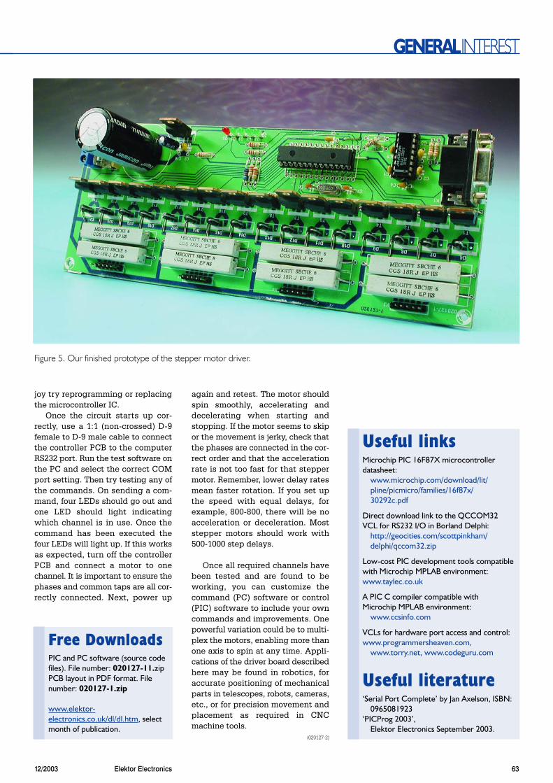
Figure 5. Our finished prototype of the stepper motor driver.
Useful linksMicrochip PIC 16F87X microcontrollerdatasheet:
www.microchip.com/download/lit/pline/picmicro/families/16f87x/30292c.pdf
Direct download link to the QCCOM32VCL for RS232 I/O in Borland Delphi:
http://geocities.com/scottpinkham/delphi/qccom32.zip
Low-cost PIC development tools compatiblewith Microchip MPLAB environment:www.taylec.co.uk
A PIC C compiler compatible withMicrochip MPLAB environment:
www.ccsinfo.com
VCLs for hardware port access and control:www.programmersheaven.com,
www.torry.net, www.codeguru.com
Useful literature‘Serial Port Complete’ by Jan Axelson, ISBN:
0965081923‘PICProg 2003’,
Elektor Electronics September 2003.
Free DownloadsPIC and PC software (source codefiles). File number: 020127-11.zipPCB layout in PDF format. Filenumber: 020127-1.zip
www.elektor-electronics.co.uk/dl/dl.htm, selectmonth of publication.