6 sheets/tyco electonics amp pdfs... · 408–7424 checking terminal crimp height or gaging die...
TRANSCRIPT
�11-*$"4*0/ �1&$*'*$"4*0/
�#��� $&��%�� ����! � �#�" ������� ������
��� �
� 0' ����� �8$0 �-&$420/*$3 �02102"4*0/� �"22*3#52(� ���-- �/4&2/"4*0/"- �*()43 �&3&26&%�� -0(0 "/% �8$0 �-&$420/*$3 "2& 42"%&."2,3���2"%&."2,� �4)&2 120%5$43� -0(03� "/% $0.1"/8 /".&3 53&% "2& 4)& 1201&248 0' 4)&*2 2&31&$4*6& 07/&23�
������� ���������� ������ �� ��������������� �� ����������� �� ���������
�)*3 $0/420--&% %0$5.&/4 *3 35#+&$4 40 $)"/(&��02 -"4&34 2&6*3*0/ "/% �&(*0/"- �5340.&2 �&26*$&�6*3*4 052 7*4& "4 '''�%(�!����%#! ��$��!�
��#�� ��$� �"����$� � � � � �"$ �� ��� � �&6 �
�&& (.' +$��& /�&. , �+ $( ' -+$� .($-, �0$-# ���� �.,-)'�+1 .($-, $( �+��% -,�� �$' (,$)(, �+ $( '$&&$' - +, ��(�$(�# ,�� �(& ,, )-# +0$, ,* �$!$ �� �$' (,$)(, #�/ � -)& +�(� )! ���� ������� �(� �("& , #�/ � -)& +�(� )! ����$".+ , �(� $&&.,-+�-$)(, �+ !)+ $� (-$!$��-$)( )(&1 �(� �+ ()- �+�0( -) ,��& �
�� ������� ����
This specification covers the requirements for application of PIDG terminals, splices, and end caps in variousoperating environments. Each consists of a precision–formed metal wire barrel and a copper sleeve encased ininsulating material made of nylon, polyvinyl chloride (PVC) or polyvinyl fluoride (PVF2). The insulation is colorcoded (solid primary color or a primary color with a color stripe) to correspond with a specific wire size or wiresize range. The terminals, splices, and end caps accept a combination of solid and stranded wire. The wirebarrel contains serrations that provide maximum contact and tensile strength after crimping the terminal, splice,or end cap onto the wire. The terminals are available with a variety of tongue lengths and configurations; andthe terminals, splices, and end caps are available with various wire barrel lengths and diameters toaccommodate different wire sizes, wire types, and combination of wire sizes.
The terminals, splices, and end caps are available in loose piece form to be terminated with manual andpneumatically–powered hand held tools and tape mounted to be terminated with bench mount semi–automaticmachines.
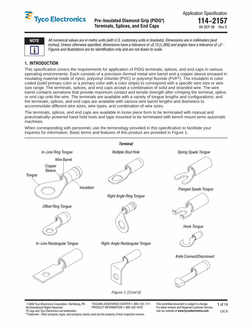
When corresponding with personnel, use the terminology provided in this specification to facilitate yourinquiries for information. Basic terms and features of this product are provided in Figure 1.
�$"#- �("& �$(" �)(".
�$"#-��("& � �-�(".&�+ �)(".
�.&-$*& �-.� �)&
Figure 1 (Cont’d)
�(��$( �$(" �)(".
�(��$( � �-�(".&�+ �)(".
�!!, - �$(" �)(".
�($! )(( �-��$,�)(( �-
�))% �)(".
�*+$(" �*�� �)(".
�&�(" � �*�� �)(".
�011&2�-&&6&
�/35-"4*0/
��������
�0/(5&
!*2& �"22&-
����
�

�� � ��%!�"� &� �$ ���&� �"� �"� ��$& ������
��� �� �� �� � � ��� ����� � �����������
Figure 1 (End)
������
� ���� ������������ ������
�����������
����� ����� �������� �����
��� ��
����������
���� � ��
�� ��������� ��������
���� ��)�&�#" �(!!�%+
Revisions to this application specification include:
� Updated document to corporate requirements� Added NOTE to Paragraph 3.5, I� Added specifications to Paragraph 2.6� Removed Applicator 818057–2 and Machine 818380–1
���� �(&'#!�% �&&�&'�"��
Reference Product Base Part Number 51864 and Product Code 3022 are representative of PIDG terminals,splices, and end caps. Use of these numbers will identify the product line and expedite your inquiries through aservice network established to help you obtain product and tooling information. Such information can beobtained through a local Representative or, after purchase, by calling PRODUCT INFORMATION at thenumber at the bottom of page 1.
���� %�*�"�&
Customer Drawings for product part numbers are available from the service network. If there is a conflictbetween the information contained in the Customer Drawings and this specification or with any other technicaldocumentation supplied, call PRODUCT INFORMATION at the number at the bottom of page 1.
���� �$�������'�#"&
Product Specification 108–11023 provides test and performance results for insulated terminals and splices forClass 1 E Nuclear applications.
��� �"&'%(�'�#"� ��'�%��
Instruction Sheets (408–series) provide product assembly instructions or tooling setup and operationprocedures and Customer Manuals (409–series) provide machine setup and operation procedures. Documentsavailable which pertain to this product are:
408–1261 Hand Crimping Tools 59239–4 and 59287–2408–1559 Hand Crimping Tools 46121, 47386, and 47387408–1610 “T”–Head Crimping Tools 59250 and 59275408–1632 Terminal and Splice Crimping Dies 69344, 47806–2, 47807–1, 47808–5, and 47808–6408–2095 Hand Crimping Tool 69710–1408–2423 Crimping Die Assemblies for Tape–Mounted PIDG Terminals and Splices408–2498 Crimping Head Cross Reference for Pneumatic Tools408–2822 Crimping Die Assemblies 59826–1, 59827–1, and 59828–1408–2823 TETRA–CRIMP* Hand Crimping Tool 59824–1408–3295 Preparing (Reel–Wrap) Reel of Contacts for Applicator Tooling408–4099 Pneumatic TETRA–CRIMP Adapter 679305–1408–4105 Straight Action Crimper 217200–[ ]
���� � *&$'�%+� �)%$� +� �'� �'� ��)+ �������
�� � � �� ����� � ������ �����������
408–7424 Checking Terminal Crimp Height or Gaging Die Closure408–8044 Miniature Quick–Change Applicator for Tape–Mounted Closed Barrel Terminals408–8053 Miniature Quick–Change Applicators408–8082 Miniature Quick–Change Applicators (Side–Feed Type) with Air Feed408–9252 PRO–CRIMPER* III Hand Crimping Tool 58433–3408–9586 Pneumatic Crimping Heads 314269–1, 314270–3, and 314537–1408–9640 Crimp Quality Monitor Applicators for Side–Feed and End–Feed Applications408–9816 Handling of Reeled Products409–1993 AMP–TAPETRONIC* Machine 69875409–5842 AMP–O–LECTRIC* Model “G” Terminating Machine 354500–1409–5862 626 Pneumatic Tooling Assemblies 189721–[ ]409–5878 AMPOMATOR* CLS IV+ Lead–Making Machines 356500–[ ]
��� �,�'��*�+ �'� �-�%$��,$('+
Military specifications provide industry test and performance requirements. Documents available which pertainto this product are:
MIL–T 7928/1, “Terminal, Lug and Splices, Conductor, Crimp Style, Copper Terminal, Lug, Crimp Style,Copper, Insulated, Ring Tongue, for Thin Wall Wire, Type II, Class I for 105�C Total ConductorTemperature”
MIL–T 7928/4, “Terminals, Lug and Splices, Conductor, Crimp Style, Copper Terminal, Lug, Insulated, RingTongue, Bell–Mounted Type II, Class I for 150�C Total Conductor Temperature”
MIL–T 7928/5, “Terminals, Lug and Splices, Conductor, Crimp Style”
MIL–T 7928/6, “Terminals, Lug and Splices, Conductor, Crimp Style, Splice, Electric, (Permanent, Type II,Class 1) for 150�C Total Conductor Temperature”
MS 17182, “Terminal, Lug, Crimp Style, Copper, Insulated (Servo Components), Type II, Class I for 125�CTotal Conductor Temperature”
MS 25036, “Terminal, Lug, Crimp Style, Copper, Insulated, Ring Tongue, Bell Mouthed, Type II, Class 1 for105�C Total Conductor Temperature”
MS 25274, “Cap, Electrical (Wire End, Crimp Style, Type II, Class 1) for 105�C Total ConductorTemperature”
�� ������������
���� �$&$,�,$('
These terminals and end caps are suitable for 300 volts maximum, and the splices are suitable for 600 voltsmaximum.
The terminals, splices, and end caps having the following insulation can withstand the following temperaturerange:
nylon –40 to 105�C [–40 to 221�F]PVC –10 to 90�C [14 to 194�F]PVF2 –65 to 150�C [–149 to 302�F]
���� �,(*�"
�� �%,*�.$(% , �$"#,
Prolonged exposure to ultraviolet light may deteriorate the chemical composition used in the insulation.
� � % �,(*�"
Tape–mounted reeled product should be stored horizontally to prevent sagging and possible stretching ordistortion of the plastic tape which could adversely affect feeding of the product through the tooling.
�� �# %! �$!
The product should remain in the shipping containers until ready for use to prevent inadvertent damage.The product should be used on a first in, first out basis to avoid storage contamination that could adverselyaffect signal transmissions.

���� �#+'%( &,� �*&%!#,� (" �(" � *, �������
�$2 � ,% �� �4", �*$"0.,+("/ �,.-,. 0(,+
�� �$#'%! & �/*),.+#
Do not store product near chemicals listed below. They could cause stress corrosion cracking of product.
Alkalies Ammonia Citrates Phosphates Citrates Sulfur CompoundsAmines Carbonates Nitrites Sulfur Nitrites Tartrates
�� �%+# �#&#!-%)( (" �+#* + -%)(
Terminals and splices accept solid and/or stranded wire sizes 26 through 10 AWG and end caps accept solidand/or stranded wire sizes 22 through 10 AWG. The wire size used must be within the range stamped on theunderside of the terminal tongue or on the center of the splice or end cap. Generally, the strip length of the wireshould be equal to the wire barrel length plus 0.76 [.030]. Specific strip lengths are given in Figure 2.
�,+#1"0,.��0. +#$# �',3+�
�)-# �,0 0, �" *$�0.(- �$+&0'��$$ � !*$�
�+/1* 0(,+
���� ��������� ��������� ��� ���
���� ����� ������
���� ����� �������� ������� ��� ���
���������� ����� �������� ������ ��� ���
�� ����� ��� ������ �$**,3��* ") ������� ��������� 5 5
�� �1*0(-*$� �$**,3 ��� ����� ������� ������� �������� 5
� �1*0(-*$� �$**,3 �� ����� ���� ������ ������� �������� 5
�� �� � �� � �� ���� �$**,3��*1$
�������� ���������� 5 5
������������ ���������� �$**,3��*1$
������� ���������� 5 5
� � �1*0(-*$��'(0$
� �� � � � ��� ��� � � � � �� ������ �1*0(-*$�� 01. *��'(0$
�������� ���������� ��� � �� ��������� 5
�������� ���������� �$#��.$$+ ������ ��������� 5 5
� �1*0(-*$��$#
� � � �� � � �� � � � � �� ������������ ��������
�� �1*0(-*$�� 01. *��$#
��� ����� ������� ������ ���������5
� �������� ���� ������ �$#��$# ������ ��������� 5 5
�� ������� ���� ������ �$#��'(0$ ������ ��������� 5 5
� �� ���� ��� ����� �*1$��*1$ ������ ��������� 5 5
� �� �1*0(-*$�� 01. *��*1$
� � � �� � � �� � � � � �� ���5
� ��� �1*0(-*$��*1$
��� ����� ������� ������ ������������������ ��������
�� ���� �1*0(-*$� �$**,3��* ") �������� ������� 5 5
�� ������� ���������� �*1$��.$$+ ������ ��������� 5 5
� �� �1*0(-*$�� 01. *��$**,3
� � � �� � � �� � �� � � � � ���5
���� �1*0(-*$��$**,3
�������� ������� �������� ���������������� ���������
� �������� ���������� �$**,3��$**,3 �������� �������� � 5 5
�� ������� ���������� �$**,3��.,3+ �������� �������� � 5 5
� Contact PRODUCT INFORMATION at the number on page 1 for acceptable insulation diameter ranges
� Large sleeve terminal designed for Class I E Nuclear applications
� For use with heavy–duty terminals having an insulation thickness of 1.02–1.27 [.040–.050]
Figure 2
���� ��)$"%�#*� �'#"��*� �%� �%� �'* ������
��) � #� ���+�# � ��'%#"��& #%$#%�'�#"
��� )�$� �"!�'�&"$�%� '%& !"& �� !������ %�$�#��� "$ �'& �'$�!� &�� %&$�##�!� "#�$�&�"!�
���� �")� �#���$�%+
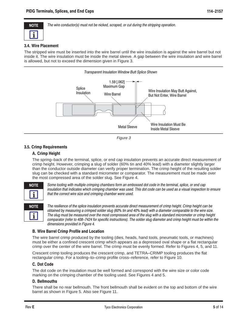
The stripped wire must be inserted into the wire barrel until the wire insulation is against the wire barrel but notinside it. The wire insulation must be inside the metal sleeve. A gap between the wire insulation and wire barrelis allowed, but not to exceed the dimension given in Figure 3.
Figure 3
��%� ��%%� ��%� �"&( �'�#" ��+ �('' ����"&'��(' �#' �"'�%� ��%� ��%%�
��� �������*�!(! ��$
��%� �"&( �'�#" �(&' ���"&��� ��'� � ��)�
�$ ����"&( �'�#"
�$�!%#�$�!& �!%'��&�"! ��!�") �'&& �#���� ��")!
��'� � ��)�
��� )"$' ��(,")�$�%+*
�� )"$' ��" !+
The spring–back of the terminal, splice, or end cap insulation prevents an accurate direct measurement ofcrimp height. However, crimping a slug of solder (60% tin and 40% lead) with a diameter slightly largerthan the conductor outside diameter can verify proper termination. The crimp height of the resulting solderslug can be checked with a standard micrometer or comparator. The measurement must be made overthe most compressed area of the solder slug. See Figure 4.
�" � &""��!� )�&� '�&�#�� �$� #�!� ��� ��$% �"$ �! � �"%%�� �"& �"�� �! &�� &�$ �!��� %#����� "$ �!� ��#�!%'��&�"! &��& �!����&�% )���� �$� #�!� ��� ��$ )�% '%��� ���% �"& �"�� ��! �� '%�� �% � (�%'�� �!%#��&�"! &" �!%'$�&��& &�� �"$$��& )�$� %�+� �!� �$� #�!� ��� ��$ )�$� '%���
��� $�%����!�� "� &�� %#���� �!%'��&�"! #$�(�!&% ���'$�&� ��$��& ��%'$� �!& "� �$� # �����&� �$� # �����& ��! ��"�&��!�� �* ��%'$�!� � �$� #�� %"���$ %�'� ���� &�! �!� �� ����� )�&� � ��� �&�$ �" #�$���� &" &�� )�$� %�+����� %�'� '%& �� ��%'$�� "(�$ &�� "%& �" #$�%%�� �$�� "� &�� %�'� )�&� � %&�!��$� ��$" �&�$ "$ �$� # �����&�" #�$�&"$ �$���$ &" � �� �"$ %#������ �!%&$'�&�"!%�� ��� %"���$ %�'� ��� �&�$ �!� �$� # �����& '%& �� )�&��! &���� �!%�"!% #$"(���� �! ���'$� �
�� �")� ��))�# )"$' �)&�"#� �%� �&��+"&%
The wire barrel crimp produced by the tooling (dies, heads, hand tools, pneumatic tools, or machines)must be either a confined crescent crimp which appears as a depressed oval shape or a flat rectangularcrimp over the center of the wire barrel. The crimp must be evenly formed. Refer to Figures 4, 5, and 11.
Crescent crimp tooling produces the crescent crimp, and TETRA–CRIMP tooling produces the flatrectangular crimp. For a tooling–to–crimp profile cross–reference, refer to Figure 10.
� �&+ &��
The dot code on the insulation must be well formed and correspond with the wire size or color codemarking on the crimping chamber of the tooling used. See Figures 4 and 5.
�� ��##$&,+!*
There shall be no rear bellmouth. The front bellmouth shall be evident on the top and bottom of the wirebarrel as shown in Figure 5. Also see Figure 11.
����
�
����
�
����
�

���� �")&$'�%*� �(%$ "*� �'! �'! �(* �������
�'6 � 0( �� �8%0 �-'%420/+%3 �02102#4+0/
�+%20.'4'2 02�0.1#2#402
�2'3%'/4 �2+.1��'12'33'& �6#- �*#1'� �
�-#4 �'%4#/)5-#2�2+.1 �
�'/4'2 0( �034�0.12'33'& �2'# ��'('240 �#$-' (02 �2+.1 �'+)*4�
�04 �0&'�� �04 �*07/�
�0-&'2 �-5)
C Produced by Crescent Crimp ToolingF Produced by TETRA–CRIMP Tooling
����� ���� ����� ����� ������ � � �� �������� �� ��� � ����� ������ �� �������
�04 �0&'�� �04 �*07/� �2+.1 �6'/-8 �02.'& �6'2
�'/4'2 0( �+2' �#22'-
�������� ���� ������� ����
���� ���������
��������� ���� ���� ��� �� ��� ���
���� �����������
�� ��� ������������ ����
��� ����������� ��� ��� ���� ���� �� ��������
��"()"**"! �+�% �#�("� ����
'--07��-#%,
�� '--07� �04 �� ! ��" � � � �� ! � � �"
� '--07� �04 ��� !���" �� ������ !�� ��� �" :
� '--07��-5'
� ��*+4'
�043 �� ! ��" �� ! ��� ���"����#452#-��*+4'
�043 ��� !���" � ���� !���������" :
�'&��2''/ � �04
� �'&
� �04 �� ! ��" �� � ! ��� ���" � �� �� ! ��� �� "�� �#452#-��'&
� �04 ��� !���" ������ !���������" �������� !�������� "
� �'&��'& � �04
�� �'&��*+4' � �04 �� ! ��" � �� ! ��� ��" � �� ! �� ���"
� �-5'��-5' �043��� !���" ������ !��������" ������ !��������"
� ���-5'
�043� ����#452#-��-5'
�043��� !����" ������ !��������" ������ !��������"
�� �-5'��2''/ �043
� ���� '--07��-#%, � �04
� '--07� '--07 � �04
� �� '--07
� �04 �� !���" �������� !�� ������" ������ !������ "
�����#452#-� '--07
� �04
�� '--07��207/ � �04
� �02 53' 7+4* *'#68 &548 4'2.+/#-3 *#6+/) #/ +/35-#4+0/ 4*+%,/'33 2#/)' 0( ������� !���������"�
Figure 4

���� ��$ �!��%� �#����%� �!� !� ��#% �������
��* $� ���-�$ �!��(&$#��' $&%$&�(�$#
Figure 5
��&� ��.� ��& �#���(���' ��&� ��.�
�*�&'(&�'' ��& ' �$(�%%�&�#( $# #')!�(�$# ��&� $#�)�($&�'� ��'��!� ��(��# ���'
�&�� ��,��%( �%!��� �#� �#� �%���� �(��! � �#� �(��! ��
�&$#( ��!!"$)(� �*���#(��$% �#� �$(($" $� ��&� ��&&�!�
$( $�� �� $( ��$+#� �' ��!! �$&"�� �#� $&&�'%$#�'��(� &�"%�#� ��"��& $� �$$!�#� �'��
��&� #')!�(�$# #'��� ��(�!�!��*� �)( �$( #'��� ��&� ��&&�!
�$ �!�'� �# ���' �&��
��&� �$(($"���# �#� �% ������� � ��
��� �������
�$ ���& ��!!"$)(�
��&� �!)'� ($ �#� $� ��&� ��&&�! $&�$(($"�� $# �($% #'��� �#(�& $� �%!���
�"&� ��&"�#�! ��$+# / ��"� �%%!��' ($ �%!��� �#� �#� �%
������ � � �� ��������� � � �����
� ���%�
There shall be no flash or extruded insulation material visible in the most compressed area of the wirecrimp. See Figure 5.
�� ��$ �!��� �#����� "$ !� ��# �!%'��&�"!
The insulation of the terminal, splice, or end cap must not be cut or show uneven stress marks orhighlighted marks on the insulation. See Figure 5.
�� ��$� �"��&�"!
1. Terminals shall have the wire ends flush or extended slightly beyond the end of the wire barrel asshown in Figure 5.
2. Splices shall have the end of the wire located against the wire stop inside the center of the splice.
3. End caps shall have the end of the wire bottomed in the end cap.
�� �!%'��&�"! �$� # �����
The insulation crimp must capture the wire insulation. The wire insulation must not be crimped inside thewire barrel of the terminal, splice, or end cap. The wire insulation must be inside the metal sleeve toprovide strain relief for the wire. See Figure 5.
The hold of the insulation crimp can be tested by using the bend test which, if successful, indicates thatthe hold is not too loose. The bend test must be performed as follows:
1. Using an unstripped wire, make a test crimp.
2. Hold the terminal, splice, or end cap in one hand. Use the side of one finger on the other hand atapproximately 76 [3] to push the wire up 90� and down 180�, one time each. Refer to Figure 6.
If the wire insulation comes out during the bend test, the insulation crimp is not tight enough, and thetooling must be adjusted to produce a tighter insulation crimp. Figure 8, Detail A shows a crimp that is tooloose, providing little or no support for the wire.

���� �*40.1&/5� �3/.(*5� &1) �1) �&35 ������
��( �� "� � �*�" � ��&$"!��% �"$#"$�&�"!
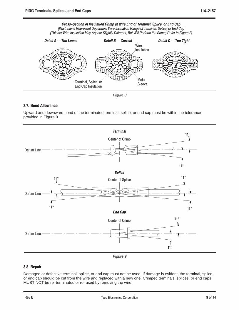
If the crimp passes the bend test, the insulation crimp must be tested by pulling the wire from the terminal,splice, or end cap. If the wire insulation is only slightly deformed, the crimp is correct. Figure 8, Detail Bshows a desired crimp, providing adequate support without damage to either the insulation or the wireconductor(s). If there is visible damage, such as tearing or piercing of the insulation, the crimp is too tight,and the tooling must be adjusted to produce a looser insulation crimp. Figure 8, Detail C shows a crimpthat is too tight, damaging the insulation and possibly breaking wire conductor(s) or reducing circular milarea (CMA) by wire extrusion.
Figure 6
��� ���
�26*� �"& &" ��� �
�� ������� ��� � ����� �������� ����
���� ��� ��##$")�
��°�%& �'%�
� �°�!� �'%�
��� �*15./* �64*1,6-
Crimped terminals, splices, or end caps should hold the wire conductor(s) firmly and have a pull–test tensilevalue meeting that specified in the table in Figure 7.
������ ������� ������� � ����� ��� �� � �� ��� �� ���� ����� ��� ������� ������ �� �� �� �� ��� ����� ��� � �������
!��� ��#� ������� ����� ��7// �*56� �*86215 $/'�+24(*%
��!�� ���������� ��� �������� �������" ��� ��������
�� ��� ��� ���� ���
� ���� �� � ����
�� ��� � � ���� ���
�� ��� ���� � ����
� ��� ���� ����� �� �
�� ���� ���� ���� ���
� ���� ��� ���� ����
�� ���� ���� ��� �����
�� ���� � �� ����� ����
Figure 7
����
�
���� ��"�����#� �!����#� ��� ��� ��!# ������
��� � � �� �� ��� ����������� �����������
Figure 8
������ � � ��� ���� ������ � � ������� ������ � � ��� �����
����������
�������� ������� ����� ��� ����������
��������������
������������� �� ��������� ����� �� ��� ��� �� ��������� ������� �� ��� �������$"#!�#���" �� !�"��# � �!��"# ��!� ��"$��#��� ����� �� ��!������ � ����� �! �� ��
�������! ��!� ��"$��#��� �% � ��! �����#�% ����!��#� �$# ���� ��!��!� #�� ����� ����! #� ���$!� ��
��� ���� �� $����
Upward and downward bend of the terminated terminal, splice, or end cap must be within the toleranceprovided in Figure 9.
Figure 9
��°
��°
��°
��°
��°
��������
������
��°
����� ���
����� ���
������ �� ������
��� ���
��°
��°
����� ���
������ �� �����
������ �� �����
���� ��!��"
Damaged or defective terminal, splice, or end cap must not be used. If damage is evident, the terminal, splice,or end cap should be cut from the wire and replaced with a new one. Crimped terminals, splices, or end capsMUST NOT be re–terminated or re–used by removing the wire.

���� �#,(&)�'-� �+'&!#-� �)" �)" ��+- ������
�� ��� �� �� ��� � ������ �����������
� �� ����� �����
Most, but not all, PIDG terminals, splices, and end caps are Listed by Underwriters Laboratories Inc. (UL) inFile E13288 and Certified by CSA International in File LR7189
�! ��&�$�� � )��&��$ � &�$�� ��� %"����� !$ � � ��" ���� &����� �* "�$& '���$� ���&% &�� $�#'�$��� &% !� � ��� �*��! &��& ������ � ������� �& &�� '���$ �& &�� �!&&!� !� "��� ��
� �������
Hand tools for manual application of loose piece terminals, splices, or end caps, and automatic andsemi–automatic machines for power assisted application of tape–mounted terminals, splices, or end caps areavailable to cover the full wire size range. Tooling part numbers and instructional material packaged with thetooling are shown in Figure 10.
�����&�! !� &!!�� � )��� ��"� � ! &�� &�$�� ��� %"����� !$ � � ��" $�#'�$��� &% %'�� �% #'� &�&* !� &�$�� �&�! %�!"�$�&!$ &$�� � � � � %����� � � &�� �(������� %'""!$& �#'�"�� & �����&$����� " �'��&��� �&��� � &�� )!$� �$��� �!��������%�� % � � ����&�! �� &!!�� � �! ��"&% ��* �� �(������� &! ���& !&��$ "$!�'�&�! $�#'�$��� &%� !$ ����&�! ��� �!$��&�! � �! &��& ! � !� &�� %�$(��� �$!'"% �& &�� �!&&!� !� "��� ��
��� ��)" �**'-
Hand tools consisting of a handle assembly with integral fixed jaws or dies and hand tools that accept variousdie assemblies are available for loose piece terminals, splices, or end caps. Both types feature a ratchet toensure full crimping pressure is applied to the terminal, splice, or end cap.
��� �&# --#( '&#-
Die assemblies are precision tools that form the wire barrel of the terminal, splice, or end cap onto theconductor(s) of the wire and form the optimum crimp height. The die assemblies consist of stationary andmovable dies that are designed for a specific wire size and terminal, splice, or end cap.
� �**-# �&#!# �#,(&)�'� �+'&!#� *, �)" ��+
These die assemblies can be used in either manual or power assist tools.
�� ��+#��*/).#" �#,(&)�'� �+'&!#� *, �)" ��+
These die assemblies are designed for use in applicators installed in power units.
��� ++'&!�.*,-
Applicators are used in power units for large production applications. They feature an automatic feedmechanism, adjustable crimp height pads, and precision crimping dies. They have been designed to simplifytooling changes and avoid unnecessary duplication of power units.
�� ��� �)#/(�.&! �**'&)$ �1-.#(
This pneumatically operated tooling system will crimp the full wire size range of the terminal, splice, or end cap.The system is a pneumatic power unit available with a logic control for foot pedal operation or without footpedal for hand operation. It is designed to accept various types of crimping heads, including those that willaccept die assemblies for loose piece terminals, splices, or end caps.
�� �*0#, �)&.-
Power units provide the force needed to operate the applicator.
� �#)!%��*/).#"
AMP–O–LECTRIC Model “G” terminating machine and AMP–TAPETRONIC machine are designed toaccept hand–fed pre–stripped wires.
�� �'**, �.�)"&)$
The AMPOMATOR CLS IV+ lead–making machine can be set up to automatically cut the wire to lengthand terminate it at a high rate of speed.
����
�
����
�

���� �"*&$'�%+� �)%$ "+� �'! �'! �)+ ������
�%4 � �� .& ���7#. �+%#20.-)#1 �.0/.0!2).-
�-%3,!2)# �0),/)-' �%!$1��%&%0 2. �!"+%��������� �
�20!)'(2 �#2).- �0),/%0������ ��##%/21 �++�)% �11%,"+)%1 �)12%$ )-�!"+%� ����������
����������� �!-$�0),/)-' �..+ �������
����������� ��� �!-$�0),/)-' �..+ ��������
���� ���� ��� ��� ���������������� �� ���� ��� ��� �������
8����%!$ �!-$ �..+1����� ��� ������ ���
�.3"+% �#2).- �!-$ �..+1������ ����������
��� �������� ������ ������
�%0,)-!+ !-$ �/+)#%�)% �11%,"+)%1������ �
�%!47 �%!$ �!-$ �..+1������ ������ ��
�!-$ �0),/)-' �..+ ��������##%/21 �++ �)% �11%,"+)%1�)12%$ )- �!"+%� ���������
����������� �-%3,!2)#�$!/2%0 ��%&%0 2. �!"+%�����������
�-%3,!2)# �..+)-'�11%,"+)%1 ������� ������� �
�..+ �.+$%0 �11%,"+7���� �� ��,!++�
����� � �� ���� ��� ��� �� �� ��� ��
�..+ �.+$%0 �11%,"+7������� ��20!)'(2 �#2).-�
�..+ �.+$%0 �11%,"+7���� ��� ��!0'%�
���� �������� ���� �������� �������
������� ��������� ���� C ���� �� C ������ ����
��'! �((% F���� ��������'! �((% C ���� C *$&)$'#
�"�! C������ ����
�!�),"* F
������������C
� � �� ���� 9 9 9 ������ 9 �� �����
��� 9 ���� 9 9 9 9 9 9
�� ��� ���� ������ ���� 9 ����� 9 ���� �
�� ���� ���� ���� ������ ���� 9 �� ��� 9 �������
� ����!-$ ����
9 9 ������ ��������� .0������
9 ������������� .0��������
� �.0 31% 5)2( 2%0,)-!+1 (!4)-' !- )-13+!2).- 2()#*-%11 0!-'% .& ��������� ������� �
� �.0 31% 5)2( (%!47 $327 2%0,)-!+1 (!4)-' !- )-13+!2).- 2()#*-%11 .& ������� ����� ����� �
��.0 31% 5)2( 5)0% (!4)-' ! ,!6),3, )-13+!2).- $)!,%2%0 .& �� ���� �
C P0.$3#%1 �0%1#%-2 �0),/F �0.$3#%1 �+!2 �%#2!-'3+!0 �0),/
��.0 31% 5)2( �..+ ������ .0 �0),/%0 ������
Figure 10 (Cont’d)

���� �#-)&* (.� �,(&!#.� *" �*" � ,. ������
�(7 �� 1) � 9&1 �.(&5310,&4 �13213$5,10
�,( �44(/%.,(4 ����� ������ ������������ $0' ����� ��������
�,( �44(/%.,(4 ����� �����$0' ���� �������
���� ��� ����� �$&+,0(���� ���������
������ �� ��� �!��($'��$-,0* �$&+,0( � � ���" #����� ����
��������� ��� �1'(. :�� (3/,0$5,0* �$&+,0( � � �������� ���
�,0,$563( �6,&-��+$0*( �22.,&$513 ������ ���������
�,0,$563( �6,&-��+$0*( �22.,&$513���� �� ��������� �
����������� ���� ��� ��� �� �� ��� ��
���� ������� ��� ���� �� �����������
���� ���� ����� ���
���� ����� ���
��� ������� ���� ��������� !%&*#
������������ �+"#( 0���#-)&* /&*$ � !%&*#
���� ��� ��� ����# "�� '&*$ � !%&*#
�� �����C
�� ����C 13 ����F
����� �����C 13 ����F �0&.6'(' 8,5+ �$&+,0( ������ ���� ��
���� $0' ��������C 13
�����F 13 �����C
� For use with terminals having an insulation thickness range of 0.51–0.84 [.020–.033].
� For use with heavy duty terminals having an insulation thickness of 1.02–1.27 [.040 –.050].
�For use with wire having a maximum insulation diameter of 7.62 [.300].
C Produces Crescent Crimp
F Produces Flat Rectangular Crimp
Figure 10 (End)

���� �'-*(+$).� �,)(%'.� $+& �+& �$,. �������
�� � �� �� ����� � ������ �����������
� ������ ���
Figure 11 shows a typical application of PIDG terminals, splices, and end caps. This illustration should be usedby production personnel to ensure a correctly applied terminal, splice, or end cap. Applications which DO NOTappear correct should be inspected using the information in the preceding pages of this specification and in theinstructional material shipped with the product or tooling.
FIGURE 11. VISUAL AID (CONT’D)
��� �� ��������� ������� ����� ��� ���� ��� � ��� �� ��������
����� ���� � �����"������ ������ �������� ��� �����
���������� �� ��������� ������� �� ��� ������� � ������ ���� ��� ����������
��� ���� � ���� ���� ��� �� ��� �����
�� ������� ��� ��� ���� ���� � ��� ������ ��� ���������� ��� ��� ��#� ������� �� �������
��������� ������� �� ��� ������� � �������� ��� ���� ����� ����� �!��
���������� �� ��������� ������� �� ��� ������� � �����" ������ ���������������� �����
��� ���������� ���� � ����������� ������ �� ���������������� �� ��� ���
���������� �� ��������� ������� ����� ��� ���� ��� � ��� �� ����
����� ������������ � �������
��� ���� � ��������� ��� ���
���� ��� ���� � ������� ��� �� ��� ������� ������� �� ����

���� �!'$"%�#(� �&#"�!(� �% �% �&( ������
�� ��� �� �� ��� � ������ �����������
FIGURE 11. VISUAL AID (END)
������ ����
�� � �������� �� ��� ������
����� ��������� ����� �� ����������
����� ����������� ��� ��� �������� ���� ������
����� ������ �� ��� ������������ ���� ��������� ���� ������ ������ � ������ � ���������� ��� ���� ���� � ���� ���
�������� ����
�� � ��� �� ���� �� ��� ������
�� ��������� ����� �� ���� ������
�� ��� ������������ ���� ��������� ���� ������
����� ��������� ����� �� ������������� �����
�� ��������� �������� �� ���� ������
��� �� � ��� ������������ ���� ��������� ���� ������
�� � ��� �� ���� �� ��� ������
������ � ������ � ���������� ��� ���� ���� � ���� ���
������ � ������ � ���������� ��� ���� ���� � ���� ���
�� ��������� ����� �� ����������