6 specific areas
TRANSCRIPT

8/21/2019 6 Specific Areas
http://slidepdf.com/reader/full/6-specific-areas 1/98
COURSEFACILITIES LAYOUT TRAINING
LAYOUT OF FACILITY – SPECIFICAREAS
1
8/21/2019 6 Specific Areas
http://slidepdf.com/reader/full/6-specific-areas 2/98
FACILITIES LAYOUT TRAINING COURSE
LAYOUT OF FACILITY - SPECIFIC AREAS
• Wellhead area
• Helideck
• Accommodation
• Control room
• Cranes & Lifting equipment / Mechanical handling & access
• Crane study / requirements,
• Lifting Equipment & methods
• Transport ways/routes
• Laydown areas / storage areas
2

8/21/2019 6 Specific Areas
http://slidepdf.com/reader/full/6-specific-areas 3/98
LAYOUT OF FACILITY - SPECIFIC AREAS
WELLHEAD AREA
References:
• Maersk Oil (Qatar), Drilling Department, Specifications toWellhead Platforms
• Total, GS EP SAF 226, Completed Wells, Safety Systems andSafety Rules
• Total, GS EP SAF 021, Layout
• NORSOK L-002, Piping system layout, design and structuralanalysis
• API RP 14E, Design and Installation of Offshore ProductionPlatform Piping Systems,
3

8/21/2019 6 Specific Areas
http://slidepdf.com/reader/full/6-specific-areas 4/98
LAYOUT OF FACILITY - SPECIFIC AREAS
WELLHEAD AREA – WELLHEAD & CONDUCTOR
• Maersk Oil Qatar:
• Standard conductor size is 30”(template drilled wells)
• Standard conductor size is 20”(drilling on permanent jacket)
• Largest diameter on wellhead isthat of the NT-2 connector: 283/8” (721 mm)
• The NT-2 connector allows easy
and quick dismantling of the x-mass tree
4

8/21/2019 6 Specific Areas
http://slidepdf.com/reader/full/6-specific-areas 5/98
LAYOUT OF FACILITY - SPECIFIC AREAS
WELLHEAD AREA – WELLHEAD & CONDUCTOR
• Wellhead:
5

8/21/2019 6 Specific Areas
http://slidepdf.com/reader/full/6-specific-areas 6/98
LAYOUT OF FACILITY - SPECIFIC AREAS
WELLHEAD AREA – MOQ NEW WELLHEAD
6
New wellhead + x-mas tree – startup
Multibowl wellhead
with B and C sectionsand valves to these
May also becompleted or modified
with a D sectionwellhead

8/21/2019 6 Specific Areas
http://slidepdf.com/reader/full/6-specific-areas 7/98
LAYOUT OF FACILITY - SPECIFIC AREAS
WELLHEAD AREA – MOQ NEW WELLHEAD
7
Different options withthe new wellhead
system

8/21/2019 6 Specific Areas
http://slidepdf.com/reader/full/6-specific-areas 8/98
LAYOUT OF FACILITY - SPECIFIC AREAS
WELLHEAD AREA – VETCO GRAY COMPACT
8
Vetco Gray compacttree, 5k / 6.5k

8/21/2019 6 Specific Areas
http://slidepdf.com/reader/full/6-specific-areas 9/98
LAYOUT OF FACILITY - SPECIFIC AREAS
WELLHEAD AREA - ARRANGEMENT
Arrangements – circle or row:
• Tripod platforms/monotowers, wells in caison: Circle arrangement
• Conventional 4-legged wellhead platforms: Row arrangement
9

8/21/2019 6 Specific Areas
http://slidepdf.com/reader/full/6-specific-areas 10/98
LAYOUT OF FACILITY - SPECIFIC AREAS
WELLHEAD AREA – CIRCLE ARRANGEMENT
10
6 wells and 2 risers insidea 5 m dia column
15 wells inside a 5 m diacolumn. The trees are staggeredand located on two differentdecks
In this arrangement, min. center-center distance between wells: 1 m– more distance required if larger / higher rated wellhead / X mass

8/21/2019 6 Specific Areas
http://slidepdf.com/reader/full/6-specific-areas 11/98
LAYOUT OF FACILITY - SPECIFIC AREAS
WELLHEAD AREA – ARRANGEMENT IN ROW
11
Arranged in row. Larger x-mass trees (10 K, Drill-Quiptree).
Spacing x-direction: 2.25 m
Spacing y-direction: 2.0 m

8/21/2019 6 Specific Areas
http://slidepdf.com/reader/full/6-specific-areas 12/98
LAYOUT OF FACILITY - SPECIFIC AREAS
WELLHEAD AREA – FREE SPACE REQUIREMENTS
• A “black box” cylinder, dia 38” (965 mm) vertically from cellardeck and through top deck (for drilling purposes).
• Flowline from the specific well may be inside this envelope as it isremoved during drilling/work over.
• Minimum 12” diameter free cylinder from x-mas tree top upthrough to the top deck to allow installation of wireline / CT riser
• Allocate on top deck space (75” x 15”) footprint for CT BOP on topof x-mas tree.
• Sufficient free space around all valve handwheels (min. 5”distance from wheel to structure), also applies to manual master
12

8/21/2019 6 Specific Areas
http://slidepdf.com/reader/full/6-specific-areas 13/98
LAYOUT OF FACILITY - SPECIFIC AREAS
WELLHEAD AREA – FREE SPACE REQUIREMENTS• Coiled tubing BOP frame
13

8/21/2019 6 Specific Areas
http://slidepdf.com/reader/full/6-specific-areas 14/98
LAYOUT OF FACILITY - SPECIFIC AREAS
WELLHEAD AREA – FREE SPACE REQUIREMENTS
• Valves on B- and C-section of wellhead: Space for VR Tool, acylinder Ø 15”, extending 110” from well centerline.
14
VR tool

8/21/2019 6 Specific Areas
http://slidepdf.com/reader/full/6-specific-areas 15/98
LAYOUT OF FACILITY - SPECIFIC AREAS
WELLHEAD AREA – MOVEMENTS OF WELLHEADS
• Wellhead and x-mass tree grows vertically when a cold well isstarted.
• This is due to the thermal expansion of the entire productiontubing, and is for example depending on the length of the welland the flowing temperature
• Typically the movement is in the range of 50 – 200 mm; exact
predicted data must be given by the company doing thecompletion.
• Further horizontal movements due to waves: About 25 mm in anydirection.
• Production flowlines will need to follow the movement; i.e.flowlines are subject to imposed displacement
15

8/21/2019 6 Specific Areas
http://slidepdf.com/reader/full/6-specific-areas 16/98
LAYOUT OF FACILITY - SPECIFIC AREAS
WELLHEAD AREA – FLOWLINE FLEXIBILITY
• In the table below is given allowable nozze loads on the wingvalve for two different sizes of Vetco Gray compact trees.
• Also the actual allowable nozzle loads on the production and testmanifolds must be considered.
• Where large vertical movements are foreseen, there must bequite some distance from nearest well to manifold (say 5 – 10 m),and the manifold may be free to rotate.
• Flowlines will often need to be designed with expansion loops.
16

8/21/2019 6 Specific Areas
http://slidepdf.com/reader/full/6-specific-areas 17/98
LAYOUT OF FACILITY - SPECIFIC AREAS
WELLHEAD AREA – FLOWLINE FLEXIBILITY
• .
17

8/21/2019 6 Specific Areas
http://slidepdf.com/reader/full/6-specific-areas 18/98
LAYOUT OF FACILITY - SPECIFIC AREAS
WELLHEAD AREA – FLOWLINE EROSION
• Ref. To API RP 14E, sec. 5
• Where erosion may be a problem due
to solids in flow, use flow Tee (Targettee) as first bend after choke.
18

8/21/2019 6 Specific Areas
http://slidepdf.com/reader/full/6-specific-areas 19/98
LAYOUT OF FACILITY - SPECIFIC AREAS
WELLHEAD AREA – FLOWLINE EROSION
• Alternative to flow Tee – 3 Dia LRbend.
• Choke valves installed to permit easyremoval and trim changes
• Downstream flow passage within tennominal pipe diameters should be free
of abrupt changes in direction tominimize flow cutting due to highvelocity.
19Also refer to NORSOK L-002

8/21/2019 6 Specific Areas
http://slidepdf.com/reader/full/6-specific-areas 20/98
LAYOUT OF FACILITY - SPECIFIC AREAS
WELLHEAD AREA – PIPING DESIGN
• Design with double-block-and-bleed (DBB) on manifolds. A twinplug valve will have same face-to-face dimension as a ball valve.
• Design with swab-over spool for easy change from producer toinjector.
20

8/21/2019 6 Specific Areas
http://slidepdf.com/reader/full/6-specific-areas 21/98
LAYOUT OF FACILITY - SPECIFIC AREAS
WELLHEAD AREA – NORSOK L-002 RECOMMENDATIONS
• Well spacing, min. 2.5 m
• Manifolds with flanges or clamp connectors at each end for
cleaning and future expansion purposes.
• Long radius bends or flow Tee / Target Tee to be used betweenchoke and manifold.
21

8/21/2019 6 Specific Areas
http://slidepdf.com/reader/full/6-specific-areas 22/98
LAYOUT OF FACILITY - SPECIFIC AREAS
WELLHEAD AREA – DRILLING ACCESS• The top deck equipment shall allow the jack-up rig’s cantilever to
have access.
• It must be possible to reach all wells from one position of the
jack-up rig (drilling envelope); i.e. the rig must not be moved toreach specific wells
• Drilling access is designed to some specific rigs, and drillingaccess drawings are prepared before new rigs are brought in.
22

8/21/2019 6 Specific Areas
http://slidepdf.com/reader/full/6-specific-areas 23/98
LAYOUT OF FACILITY - SPECIFIC AREAS
WELLHEAD AREA – DRILLING ACCESS• (S+P+L) = 49 – 50 m for some of the listed drill rigs (North Sea)
but may be smaller in other regions. See specific rigs.
23

8/21/2019 6 Specific Areas
http://slidepdf.com/reader/full/6-specific-areas 24/98
LAYOUT OF FACILITY - SPECIFIC AREAS
WELLHEAD AREA – DRILLING ACCESS
• The top deck equipment should maximum be 28 m above meansea level, to allow the jack-up rig’s cantilever to have access.
• It must be possible to reach all wells from one position of the jack-up rig; i.e. the rig must not be moved to reach specific wells
• Drilling access is designed to some specific rigs, and drillingaccess drawings are prepared before new rigs are brought in.
24
Typical drilling
envelope:
39 ft x 24 ft

8/21/2019 6 Specific Areas
http://slidepdf.com/reader/full/6-specific-areas 25/98
LAYOUT OF FACILITY - SPECIFIC AREAS
WELLHEAD AREA – WELL SERVICE ACCESS• The top deck should contain
hatches for access to x-mass trees
• Three hatches “inside each others”,one 3000 mm, one 1000 mm andone 300 mm.
• Often only made with 3 m x 3 m
square and then circular Ø 300 mmhatches inside the large squarehatch
• Ø 300 hatches above each x-mass
tree
25

8/21/2019 6 Specific Areas
http://slidepdf.com/reader/full/6-specific-areas 26/98
LAYOUT OF FACILITY - SPECIFIC AREAS
WELLHEAD AREA – WELL SERVICE EQUIPMENT• The top deck must be sufficient in size to contain the equipment
(wire line, light coiled tubing or heavy coiled tubing).
• Must be designed for most heavy part (typically the CT reel)
• Standard coiled tubing reel (2”), weight 30 tonnes @ max 1.5 mwaves (H1/3), 15 m from boat landing
• Heavy coiled tubing reel (2 3/8”), weight 60 tonnes, foot print 2.5m x 7 m. Tubing being spooled onboard +Tank, 60 tons (4 m x 4m footprint)
• Design deck load min. 20 kN/m2 on working area of min. 20 m x20 m.
• Further space is required for CT control container, pumps, tanks,depending on the job type
26

8/21/2019 6 Specific Areas
http://slidepdf.com/reader/full/6-specific-areas 27/98
LAYOUT OF FACILITY - SPECIFIC AREAS
HELIDECK – D-MEASURE AND HELICOPTERS• Ref. CAP 437
• D-measure and design
load is characteristicsof helideck
• Restricted zones areshown here.
• 210°obstacle freezone
• 150°limited obstaclesunder an angle 2:1
(30 deg).
27

8/21/2019 6 Specific Areas
http://slidepdf.com/reader/full/6-specific-areas 28/98
LAYOUT OF FACILITY - SPECIFIC AREAS
HELIDECK – OBSTRUCTION FREE AREAS• Ref. CAP 437
28

8/21/2019 6 Specific Areas
http://slidepdf.com/reader/full/6-specific-areas 29/98
LAYOUT OF FACILITY - SPECIFIC AREAS
HELIDECK – D-MEASURE AND HELICOPTERS
29
8/21/2019 6 Specific Areas
http://slidepdf.com/reader/full/6-specific-areas 30/98
LAYOUT OF FACILITY - SPECIFIC AREAS
HELIDECK – MARKING
30
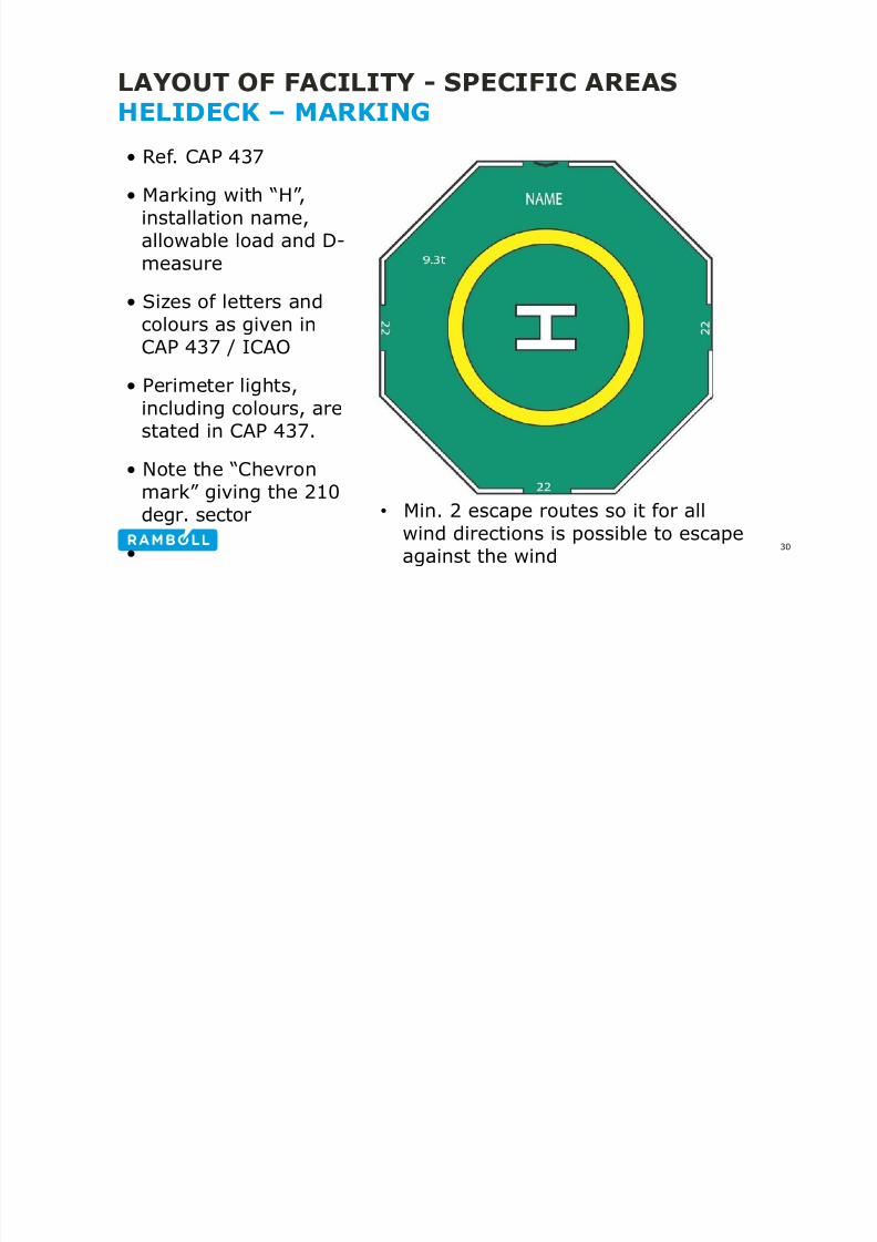
• Ref. CAP 437
• Marking with “H”,
installation name,allowable load and D-measure
• Sizes of letters and
colours as given inCAP 437 / ICAO
• Perimeter lights,including colours, are
stated in CAP 437.• Note the “Chevron
mark” giving the 210degr. sector
•
• Min. 2 escape routes so it for allwind directions is possible to escapeagainst the wind
8/21/2019 6 Specific Areas
http://slidepdf.com/reader/full/6-specific-areas 31/98
LAYOUT OF FACILITY - SPECIFIC AREAS
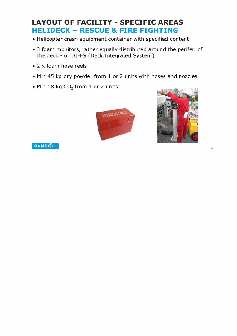
HELIDECK – RESCUE & FIRE FIGHTING• Helicopter crash equipment container with specified content
• 3 foam monitors, rather equally distributed around the periferi ofthe deck - or DIFFS (Deck Integrated System)
• 2 x foam hose reels
• Min 45 kg dry powder from 1 or 2 units with hoses and nozzles
• Min 18 kg CO2
from 1 or 2 units
31

8/21/2019 6 Specific Areas
http://slidepdf.com/reader/full/6-specific-areas 32/98
LAYOUT OF FACILITY - SPECIFIC AREAS
HELIDECK – RESCUE & FIRE FIGHTING• DIFFS (Deck Integrated Foam Forming System) with pop-up
nozzles
32
Fire water demand: 6 l/min/m2based on D-measure.
Pressure: Min. 6.5 barg
(same requirements for monitors)
http://www.youtube.com/watch?v=QyYC6RC2duo
8/21/2019 6 Specific Areas
http://slidepdf.com/reader/full/6-specific-areas 33/98
LAYOUT OF FACILITY - SPECIFIC AREAS
ACCOMMODATION
References:
• Maersk Oil, MODES 01, Safety Design
• Maersk Oil, MODES 08, Accommodation Facilities
• NORSOK C-001, Living Quarter Area
• Shell DEP 37.17.10.10, Design of offshore living quarters
• Shell DEP 30.00.60.15, Human Factors Engineering – ControlRoom Design
33

8/21/2019 6 Specific Areas
http://slidepdf.com/reader/full/6-specific-areas 34/98
LAYOUT OF FACILITY - SPECIFIC AREAS
ACCOMMODATION• Located on safest place on the
installation
• Isolated from fuel sources –greatest extend possible
• Fire wall or adequate spacing
• No risers underneath
• Minimize windows facingproduction
• Noise & Vibrations
• HVAC with F&G• Provide quick and easy escape
– at least two independentroutes
34

8/21/2019 6 Specific Areas
http://slidepdf.com/reader/full/6-specific-areas 35/98
FACILITIES LAYOUT TRAINING COURSE
ACCOMMODATIONOverall goals
• To provide an area where the POB shall be protected from harm,weather, noise and vibration.
• To provide a standard of accommodation balanced with theduration and regularity with which persons are required to resideon offshore installations
• To provide auxiliary spaces to facilitate the operationalrequirements of the installation.
• To achieve the optimum use of space and weight in terms of livingconditions and cost effective layout through appropriate functional
suitability, aesthetic appearance and coordinated interiorarrangements.
35

8/21/2019 6 Specific Areas
http://slidepdf.com/reader/full/6-specific-areas 36/98
FACILITIES LAYOUT TRAINING COURSE
ACCOMMODATIONSpecific goals
• Provide design brief with requirements and the basis of design
• Provide adequate spaces to fulfil welfare needs in terms of areasfor
• Sleeping and resting
• Personal hygiene
• Catering and dining
• Laundry
• Recreation and leisure
• Medical facilities
• To provide adequate areas, where required, for management andcontrol functions
36

8/21/2019 6 Specific Areas
http://slidepdf.com/reader/full/6-specific-areas 37/98
FACILITIES LAYOUT TRAINING COURSE
ACCOMMODATIONSpecific goals (continued)
• To provide good access arrangements between all areas thatpersonnel may require to use in both normal and emergency
conditions
• To provide adequate space for utility services and equipment thatare required to be located within the LQ
• To make provision in the design for utility services that makecost-effective use of space and interface efficiently with plannedor existing platform utility services
37

8/21/2019 6 Specific Areas
http://slidepdf.com/reader/full/6-specific-areas 38/98
FACILITIES LAYOUT TRAINING COURSE
ACCOMMODATIONData / Philosophies / Strategies – early stage
• type of installation;
• personnel capacity;
• manning philosophy for all main operational phases;
• catering philosophy;
• CCR philosophy (if applicable);
• environmental data on location;
• design life;
• helicopter type(s) and operational philosophy;
• main evacuation philosophy;
38

8/21/2019 6 Specific Areas
http://slidepdf.com/reader/full/6-specific-areas 39/98
FACILITIES LAYOUT TRAINING COURSE
ACCOMMODATIONData / Philosophies / Strategies – early stage
• lifeboat capacity and number;
• workshop area requirements (if applicable);
• waste handling philosophy;
• housekeeping (cleaning) philosophy.
39

8/21/2019 6 Specific Areas
http://slidepdf.com/reader/full/6-specific-areas 40/98
FACILITIES LAYOUT TRAINING COURSE
ACCOMMODATIONLQ Area Room Programme – NORSOK C-001, Annex A:
40

8/21/2019 6 Specific Areas
http://slidepdf.com/reader/full/6-specific-areas 41/98
FACILITIES LAYOUT TRAINING COURSE
ACCOMMODATIONAllocation of offices – Shell guidelines – part 1:
41

8/21/2019 6 Specific Areas
http://slidepdf.com/reader/full/6-specific-areas 42/98
FACILITIES LAYOUT TRAINING COURSE
ACCOMMODATIONAllocation of offices – Shell guidelines – part 2:
42

8/21/2019 6 Specific Areas
http://slidepdf.com/reader/full/6-specific-areas 43/98
Day/Night shift (Back to Back) can be
sized for 2 persons (only 1 at the time)
Other cabins only 1 person during
normal manning
Provisions for Bunk beds
Bed spaces is always and issue !
Capacity:
Design for maximum POB
Consider periods for increased manning
Future requirements ?
FACILITIES LAYOUT TRAINING COURSE
ACCOMMODATION
43

8/21/2019 6 Specific Areas
http://slidepdf.com/reader/full/6-specific-areas 44/98
FACILITIES LAYOUT TRAINING COURSE
ACCOMMODATION
Access and Layout
• Areas with more than 5 persons shall have at least two exits
situated as far apart as possible (MODES 01)
• Minimum door dimensions 2m * 0.8m
• Stretcher
• Medical room in vicinity to ERT
NORSOK C-001
Rooms exceeding 20 m2
44

8/21/2019 6 Specific Areas
http://slidepdf.com/reader/full/6-specific-areas 45/98
LAYOUT OF FACILITY - SPECIFIC AREAS
ACCOMMODATION
Main Accommodation area -
Typical rooms/spaces
• Cabins with Shower & toilet
• Canteen, galley, food store,refrigerator rooms, freezer,waste disposal
• Offices
• Leisure & Recreation
• Laundry & Linen room
• Medical room
• Chapel / Prayer Room
• TR (Depending on design)
45

8/21/2019 6 Specific Areas
http://slidepdf.com/reader/full/6-specific-areas 46/98
FACILITIES LAYOUT TRAINING COURSE
ACCOMMODATION
Access and Layout
• Cabin area as per NORSOK C-001
• Single 6 m2 incl. bath
• Double 12 m2 incl. bath
• Bed min. 2100 mm * 800 mm
• Shower 0.65 m2
• Shower min width (centre) 700 mm
BF Accommodation46

8/21/2019 6 Specific Areas
http://slidepdf.com/reader/full/6-specific-areas 47/98
FACILITIES LAYOUT TRAINING COURSE
ACCOMMODATIONAccess and Layout – Shell proposal for 2 x 2 persons cabin:
BF Accommodation47

8/21/2019 6 Specific Areas
http://slidepdf.com/reader/full/6-specific-areas 48/98
FACILITIES LAYOUT TRAINING COURSE
ACCOMMODATIONAccess and Layout – South Arne/DK. Single rooms
BF Accommodation48
Note that each room has window
C S O G CO S

8/21/2019 6 Specific Areas
http://slidepdf.com/reader/full/6-specific-areas 49/98
FACILITIES LAYOUT TRAINING COURSE
ACCOMMODATION
Access and Layout
• Cabins to be grouped in areas or corridors (Private Domain)
• Linen store on each floor (all cabin levels)
• Cleaner’s store on all main floor levels
• Cabin to have unobstructed access to corridor leading to
minimum two independent escape routes
BF Accommodation49
FACILITIES LAYOUT TRAINING COURSE

8/21/2019 6 Specific Areas
http://slidepdf.com/reader/full/6-specific-areas 50/98
FACILITIES LAYOUT TRAINING COURSE
ACCOMMODATION
AD Level 3
50
FACILITIES LAYOUT TRAINING COURSE

8/21/2019 6 Specific Areas
http://slidepdf.com/reader/full/6-specific-areas 51/98
FACILITIES LAYOUT TRAINING COURSE
ACCOMMODATION
Access and Layout
• Recreation areas, not less than 1.5 m2 per bed (NORSOK)
• As appropriate
• TV lounge
• Coffee bar
• Activity room
• Gym
• Grouped together
BF Quiet room51
FACILITIES LAYOUT TRAINING COURSE

8/21/2019 6 Specific Areas
http://slidepdf.com/reader/full/6-specific-areas 52/98
FACILITIES LAYOUT TRAINING COURSE
ACCOMMODATION
AD Level 252
FACILITIES LAYOUT TRAINING COURSE

8/21/2019 6 Specific Areas
http://slidepdf.com/reader/full/6-specific-areas 53/98
FACILITIES LAYOUT TRAINING COURSE
ACCOMMODATION
AD Level 253
FACILITIES LAYOUT TRAINING COURSE

8/21/2019 6 Specific Areas
http://slidepdf.com/reader/full/6-specific-areas 54/98
FACILITIES LAYOUT TRAINING COURSE
ACCOMMODATION
BF Level 154
FACILITIES LAYOUT TRAINING COURSE

8/21/2019 6 Specific Areas
http://slidepdf.com/reader/full/6-specific-areas 55/98
FACILITIES LAYOUT TRAINING COURSE
ACCOMMODATION
Access and Layout
• Dinning room
• 1.2 m2 per person for approx. 50% POB
• Near Galley and serving area
BF Accommodation55
FACILITIES LAYOUT TRAINING COURSE

8/21/2019 6 Specific Areas
http://slidepdf.com/reader/full/6-specific-areas 56/98
FACILITIES LAYOUT TRAINING COURSE
ACCOMMODATION
AD Level 256
FACILITIES LAYOUT TRAINING COURSE

8/21/2019 6 Specific Areas
http://slidepdf.com/reader/full/6-specific-areas 57/98
FACILITIES LAYOUT TRAINING COURSE
ACCOMMODATION
AD Level 2
A0 Shutter
B15 wall
A0 Cladding wall
A60 wall
A60 wall
57
FACILITIES LAYOUT TRAINING COURSE

8/21/2019 6 Specific Areas
http://slidepdf.com/reader/full/6-specific-areas 58/98
FACILITIES LAYOUT TRAINING COURSE
ACCOMMODATION
BF Level 258
FACILITIES LAYOUT TRAINING COURSE

8/21/2019 6 Specific Areas
http://slidepdf.com/reader/full/6-specific-areas 59/98
FACILITIES LAYOUT TRAINING COURSE
ACCOMMODATION
Access and Layout
• LQ Laydown area
• Waste handling
• Containers
• Access
• To Provision store
• To General Provision
BF Accommodation59
FACILITIES LAYOUT TRAINING COURSE

8/21/2019 6 Specific Areas
http://slidepdf.com/reader/full/6-specific-areas 60/98
FACILITIES LAYOUT TRAINING COURSE
ACCOMMODATION
Access and Layout
• LQ storage area
• Provision stores
• Cold Storage
• Freezer
• Main store
• Linen store -Each floor with cabins
• Cleaner’s store – Each floor
BF Accommodation60
FACILITIES LAYOUT TRAINING COURSE

8/21/2019 6 Specific Areas
http://slidepdf.com/reader/full/6-specific-areas 61/98
ACCOMMODATION
BF AccommodationAD Level 261
FACILITIES LAYOUT TRAINING COURSE
8/21/2019 6 Specific Areas
http://slidepdf.com/reader/full/6-specific-areas 62/98
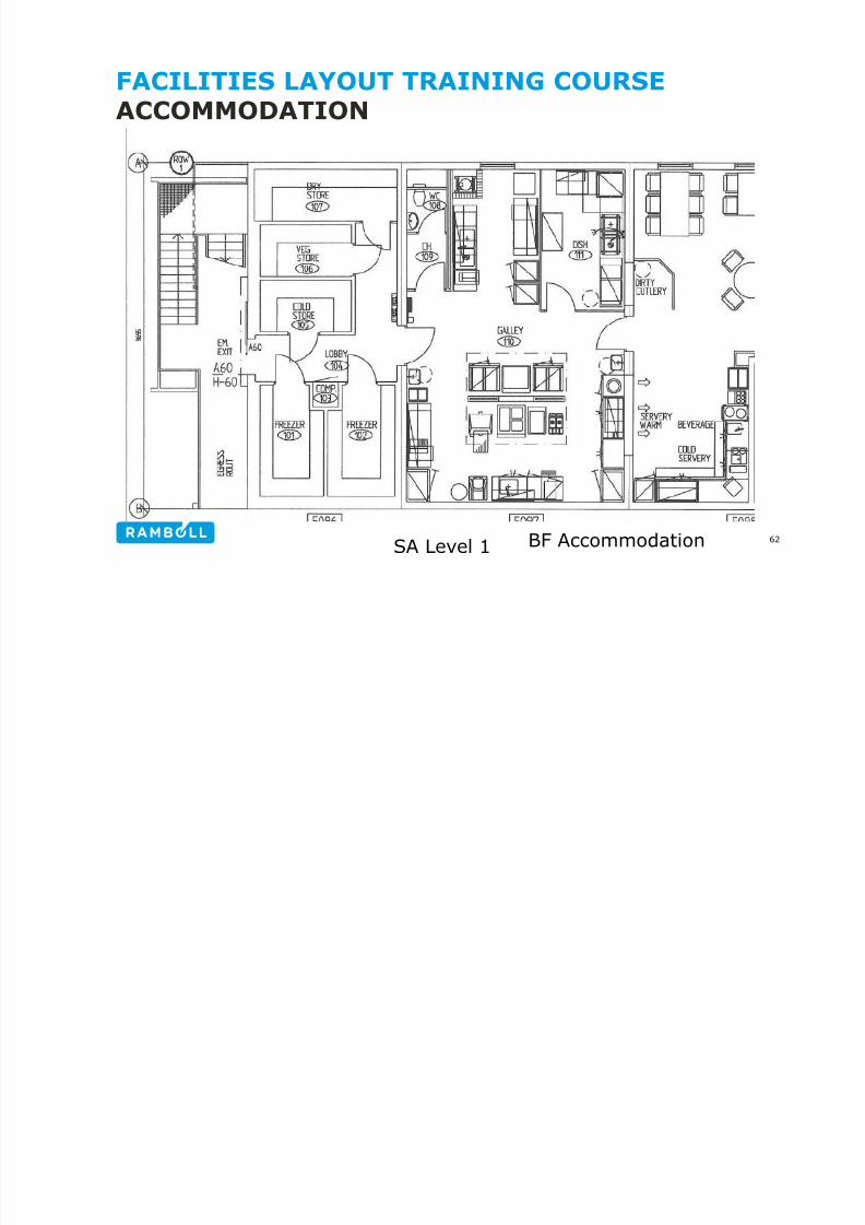
ACCOMMODATION
BF AccommodationSA Level 162
LAYOUT OF FACILITY - SPECIFIC AREAS

8/21/2019 6 Specific Areas
http://slidepdf.com/reader/full/6-specific-areas 63/98
ACCOMMODATIONWorking area in relation to
acc.
• Central Control Room – Seeseparate section
• Telecommunications & RadioRoom
• Workshops & Stores
• Laboratories
• Offices
• Changing rooms(male/female)
• ERT storage room
63
LAYOUT OF FACILITY - SPECIFIC AREAS

8/21/2019 6 Specific Areas
http://slidepdf.com/reader/full/6-specific-areas 64/98
ACCOMMODATIONUtility area in relation to acc.
• Plant rooms – Elec., battery, emergency gen.
• Potable water• HVAC & air treatment
• Firewater pumps
• Sewage treatment
Noise & Vibrations
Diesel with subsequent risk of fire and smoke
development
64
LAYOUT OF FACILITY - SPECIFIC AREAS

8/21/2019 6 Specific Areas
http://slidepdf.com/reader/full/6-specific-areas 65/98
ACCOMMODATIONFor estimates +/- 25%. Weight of LQ versus POB
65Ref. Shell DEP 37.17.10.10-Gen
LAYOUT OF FACILITY - SPECIFIC AREAS

8/21/2019 6 Specific Areas
http://slidepdf.com/reader/full/6-specific-areas 66/98
ACCOMMODATIONFor estimates +/- 25%. Area of LQ versus POB
66Ref. Shell DEP 37.17.10.10-Gen
LAYOUT OF FACILITY - SPECIFIC AREAS

8/21/2019 6 Specific Areas
http://slidepdf.com/reader/full/6-specific-areas 67/98
CONTROL ROOMStandards / Guidelines as reference:
• NORSOK S-002, Working Environment
• OGP Report 454, Human Factors engineering in projects
• ISO 11064 (1 to 3), Ergonomic design of control centres
67
LAYOUT OF FACILITY - SPECIFIC AREAS

8/21/2019 6 Specific Areas
http://slidepdf.com/reader/full/6-specific-areas 68/98
CONTROL ROOM - REQUIREMENTS• Located at a location as safe as possible, away from the work
areas (utility, process) – in non-classified area.
• Integrated platforms: In or adjacent to accommodation
• Bridge connected platforms: Where safely and functionally
• Well protected against all dimensioning hazards
• No doors directly from work area to CCR
• Toilet located in vicinity (few meters from CCR)
• Space for future expansion (control stations, desks, etc.) – 25%spare space for future 20 years
• Low noise level (< 50 dB) – well protected against vibrations
• Light level: 500 LUX
68
LAYOUT OF FACILITY - SPECIFIC AREASCONTROL ROOM REQUIREMENTS

8/21/2019 6 Specific Areas
http://slidepdf.com/reader/full/6-specific-areas 69/98
CONTROL ROOM - REQUIREMENTS
• Some companies require windows in CCR with “human factor” asargument – this is requirement in NORSOK
• Integrated with maritime control room / telecom room
• Windows at the side of control desk
• Guide (Shell): 9 – 15 m2 per control station
• Good access to
• Supporting facilities incl. production supervisor office
• Production areas
• Emergency escape routes + life boats
• Provided with – or in vicinity of:
• Work permit administration system/facilities
69
LAYOUT OF FACILITY - SPECIFIC AREASCONTROL ROOM DESIGN STEPS ISO 11064 2

8/21/2019 6 Specific Areas
http://slidepdf.com/reader/full/6-specific-areas 70/98
CONTROL ROOM – DESIGN STEPS, ISO 11064-2
70
LAYOUT OF FACILITY - SPECIFIC AREASCONTROL ROOM DESIGN ISO 11064 3

8/21/2019 6 Specific Areas
http://slidepdf.com/reader/full/6-specific-areas 71/98
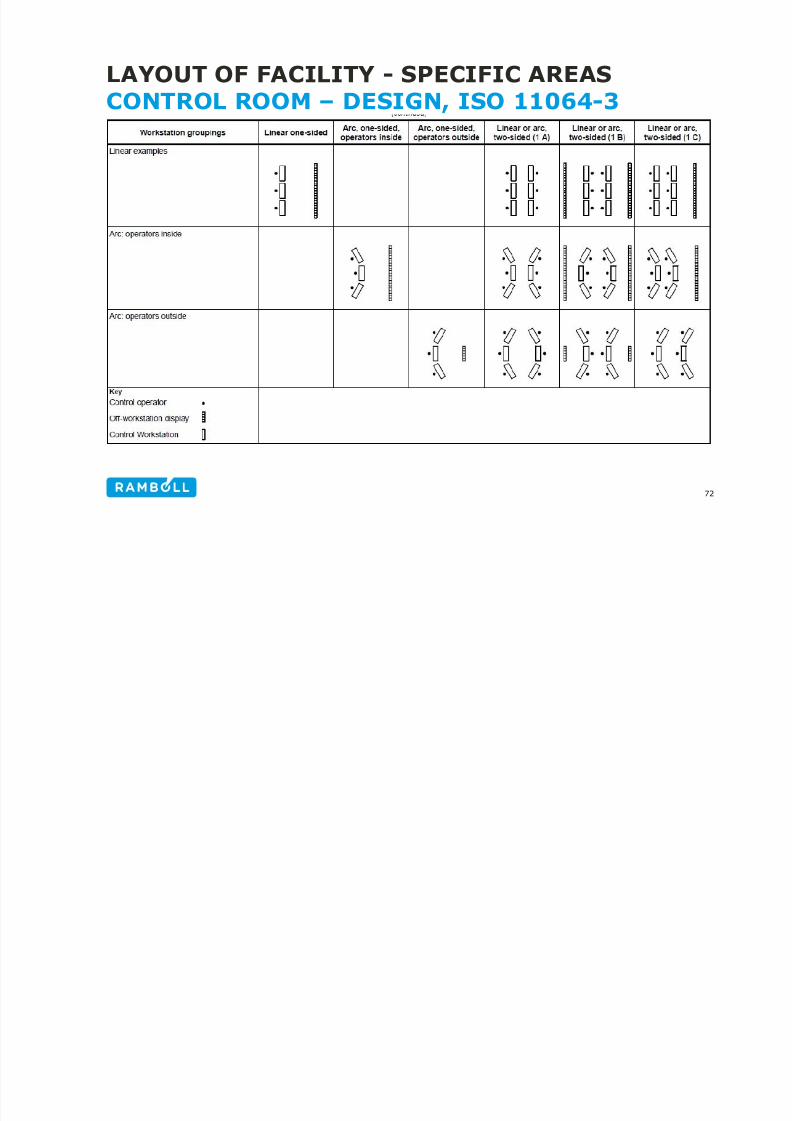
CONTROL ROOM – DESIGN, ISO 11064-3
71
LAYOUT OF FACILITY - SPECIFIC AREASCONTROL ROOM DESIGN ISO 11064 3
8/21/2019 6 Specific Areas
http://slidepdf.com/reader/full/6-specific-areas 72/98
CONTROL ROOM – DESIGN, ISO 11064-3
72
LAYOUT OF FACILITY - SPECIFIC AREASCONTROL ROOM EXAMPLE LOCATION

8/21/2019 6 Specific Areas
http://slidepdf.com/reader/full/6-specific-areas 73/98
CONTROL ROOM – EXAMPLE, LOCATION
73
Note:
Blast wall from
process areaand swith gearroom asadditionalbarrier
LAYOUT OF FACILITY - SPECIFIC AREASCONTROL ROOM – EXAMPLE LAYOUT

8/21/2019 6 Specific Areas
http://slidepdf.com/reader/full/6-specific-areas 74/98
CONTROL ROOM – EXAMPLE, LAYOUT
74
(49:F&GMatrix
Copier and
printer insame roomis not bestpractice)
LAYOUT OF FACILITY - SPECIFIC AREASCONTROL ROOM – SHELL GUIDELINE

8/21/2019 6 Specific Areas
http://slidepdf.com/reader/full/6-specific-areas 75/98
CONTROL ROOM – SHELL GUIDELINE
75
LAYOUT OF FACILITY - SPECIFIC AREASCONTROL ROOM – SHELL GUIDELINE

8/21/2019 6 Specific Areas
http://slidepdf.com/reader/full/6-specific-areas 76/98
CONTROL ROOM SHELL GUIDELINE
76
LAYOUT OF FACILITY - SPECIFIC AREASCONTROL ROOM – BAD DESIGN

8/21/2019 6 Specific Areas
http://slidepdf.com/reader/full/6-specific-areas 77/98
CONTROL ROOM BAD DESIGN
77
• Usual office desks does not give enough space for monitors
• Printers etc. located under the desks and obstruct legs of operator
LAYOUT OF FACILITY - SPECIFIC AREASCRANES & LIFTING EQUIPMENT

8/21/2019 6 Specific Areas
http://slidepdf.com/reader/full/6-specific-areas 78/98
CRANES & LIFTING EQUIPMENT• Mechanical Handling Philosophy
• Crane Study & Crane requirements
• Lifting equipment and methods
• Mechanical Handling Study / Mechanical Handling Plan
• Access / clearance requirements
• Transport ways / routes• Laydown areas
78
CRANES & LIFTING EQUIPMENTMECHANICAL HANDLING PHILOSOPHY

8/21/2019 6 Specific Areas
http://slidepdf.com/reader/full/6-specific-areas 79/98
MECHANICAL HANDLING PHILOSOPHY• Strategy for use of permanent means versus temporary / portable
• Parameters / criteria: How often, how heavy
79
CRANES & LIFTING EQUIPMENTMECHANICAL HANDLING PHILOSOPHY

8/21/2019 6 Specific Areas
http://slidepdf.com/reader/full/6-specific-areas 80/98
• Another strategy (NORSOK R-002, table B.1)
80
CRANES & LIFTING EQUIPMENTMECHANICAL HANDLING PHILOSOPHY

8/21/2019 6 Specific Areas
http://slidepdf.com/reader/full/6-specific-areas 81/98
Further the strategy must define:
• Main mechanical handling equipment available (incl. Crane)
• Description of main transport routes incl. design criteria
• Lifting restrictions, philosophy for lifting above process area
• Weather constraints
• Definition of largest / heaviest item to be handled per area anddescription of transportation route and handling equipment
• Requirements for dropped object protection and swinging loadprotection (crashbars, bumpers)
• Description of goods handled to/from helideck
• Load categories for mono rails, hoists and pad eyes.
81
CRANES & LIFTING EQUIPMENTCRANE STUDY

8/21/2019 6 Specific Areas
http://slidepdf.com/reader/full/6-specific-areas 82/98
• Basis for location of cranes and crane boom rests
• Visibility to laydown areas
• Description of handling with main cranes to/from supply boat and
internally on topside
• Listing of most common lifting operations and frequency of these
• Description of max allowable lifting heights, coverage and
restrictions.
• Personnel transport? (MOB boat, personnel basket)
• Lifting requirements including well service equipment
• Sketch: Minimum radius and max. radius for heaviest lift
• Strategy for changing hook (re-reeving) and wire change out
82
CRANES & LIFTING EQUIPMENTCRANE LOCATION / SUPPLY BOAT APPOACH

8/21/2019 6 Specific Areas
http://slidepdf.com/reader/full/6-specific-areas 83/98
• Supply boat approach on blow-off side (or prevailing wind parallelto the side being lifted from)
• No lifting over riser / pipelines
• Full visibility from crane cabin to supply boat
• Need for more cranes on same platform?
• Need for ”take-over” laydown area
83
Wind
Wind
CRANES & LIFTING EQUIPMENTCRANE STUDY / CRANE REQUIREMENTS

8/21/2019 6 Specific Areas
http://slidepdf.com/reader/full/6-specific-areas 84/98
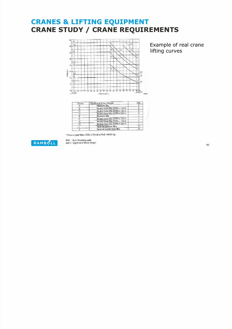
• Design: EN 13852-1, Offshore Cranes
• Max/min radius, SWL@radius,
• Offshore lifts: Max. Load/radius/wave height (typically 2.5 - 4 m)
• Approval/design for manriding?
• Additional brake on winches
• Emergency power/pumping system
• Need to rotate more than 360°?
• Mechanical & structural classification (F.E.M)
• Zone/EX requirements (incl. Zone 2 kit on engine)?
84
CRANES & LIFTING EQUIPMENTCRANE STUDY / CRANE REQUIREMENTS
8/21/2019 6 Specific Areas
http://slidepdf.com/reader/full/6-specific-areas 85/98
85
Example of real cranelifting curves
CRANES & LIFTING EQUIPMENTLIFTING EQUIPMENT & METHODS

8/21/2019 6 Specific Areas
http://slidepdf.com/reader/full/6-specific-areas 86/98
86
Offshore craneTraversecrane
Monorailcrane
Beam clamp
Lever hoist
Chain hoist
Chain sling Polyester roundsling
CRANES & LIFTING EQUIPMENTLIFTING EQUIPMENT & TRANSPORT METHODS

8/21/2019 6 Specific Areas
http://slidepdf.com/reader/full/6-specific-areas 87/98
87
Sack truck Pallet truck Turnable truck Mobile cantilever hoist
Tripod Pneumatic liftingbag
Hydraulic jacks Roller skates
CRANES & LIFTING EQUIPMENTLIFTING EQUIPMENT & TRANSPORT METHODS
8/21/2019 6 Specific Areas
http://slidepdf.com/reader/full/6-specific-areas 88/98
88
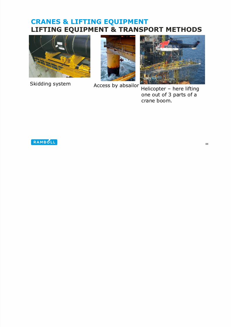
Access by absailorSkidding systemHelicopter – here liftingone out of 3 parts of acrane boom.
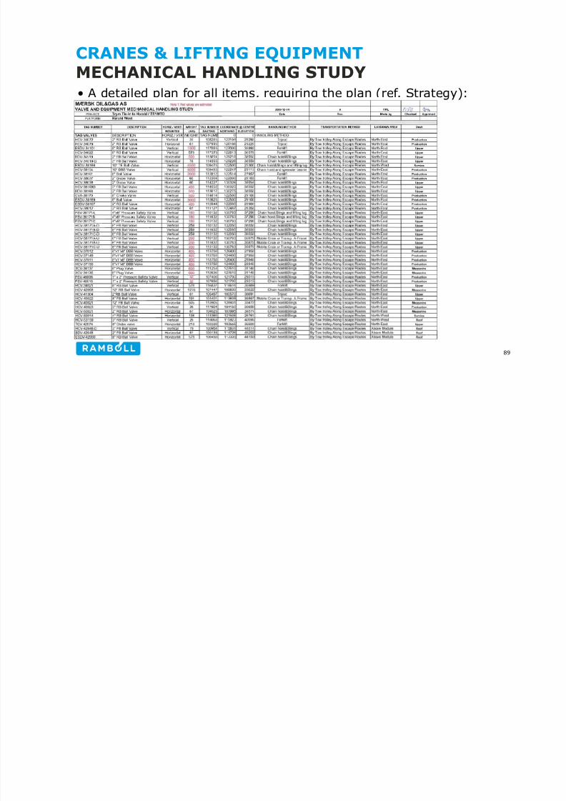
CRANES & LIFTING EQUIPMENTMECHANICAL HANDLING STUDY
8/21/2019 6 Specific Areas
http://slidepdf.com/reader/full/6-specific-areas 89/98
• A detailed plan for all items, requiring the plan (ref. Strategy):
89
CRANES & LIFTING EQUIPMENTMECHANICAL HANDLING STUDY
h l l d hd l h dl

8/21/2019 6 Specific Areas
http://slidepdf.com/reader/full/6-specific-areas 90/98
The plan must also adress withdrawal areas & handling:
• Seawater lift pumps
• S&T heat exchanger - tube bundle (required pulling points?)
• Plate heat exchanger – plate pack
• Centrifugal compressor – bundle / aero assy
• Multistage centrifugal pumps – cartridge
• Pig launchers / receivers – pig handling and space requirements
90
It may be required to
design with a gantrycrane or runway beamover equipment insidemodules
CRANES & LIFTING EQUIPMENTMECHANICAL HANDLING STUDYR b l d d ( il i i

8/21/2019 6 Specific Areas
http://slidepdf.com/reader/full/6-specific-areas 91/98
Runway beam plans are produced (some oil companies require”Mechanical Handling Layout Drawings”):
91
Also address foreach handling
equipment, howit must be loadtested duringre-certification
(need for “floating load”
CRANES & LIFTING EQUIPMENTMECHANICAL HANDLING STUDYE l ”M h i l H dli L t D i ”

8/21/2019 6 Specific Areas
http://slidepdf.com/reader/full/6-specific-areas 92/98
Example: ”Mechanical Handling Layout Drawing”:
92
CRANES & LIFTING EQUIPMENTMECHANICAL HANDLING STUDY• The tables are supported by plots from a 3D model study and

8/21/2019 6 Specific Areas
http://slidepdf.com/reader/full/6-specific-areas 93/98
• The tables are supported by plots from a 3D model study, andsketches to show the lifting/handling:
93
CRANES & LIFTING EQUIPMENTTRANSPORT WAYS / ROUTES• Must be sized to allow transportation of largest/heaviest item to

8/21/2019 6 Specific Areas
http://slidepdf.com/reader/full/6-specific-areas 94/98
• Must be sized to allow transportation of largest/heaviest item tobe handled from its position to the actual lay down area.
• No steps or tresholds on transport ways
• Consider any special transport remidies (fork lift, pallet lifter, etc)
• Transport to mech. Workshop must be possible for items inquestion.
• A goods elevator should be considered for transport betweenlevels
• Transportation both horizontally and vertically must beconsidered.
94
CRANES & LIFTING EQUIPMENTLAYDOWN AREAS / STORAGE AREAS• Preferably at periphery preferably in unclassified areas

8/21/2019 6 Specific Areas
http://slidepdf.com/reader/full/6-specific-areas 95/98
• Preferably at periphery, preferably in unclassified areas
• Preferable be visible from the crane
• If more than one crane, a laydown area for ”take-over”
• Laydown area for accomodation containers
• Laydown area for tote tanks (chemicals, etc.). Far fromaccomodation
• Laydown area for containers generally
• Laydown area / deck space for well service equipment
• Laydown area for ”service containers” + equipment for backload
• Laydown areas must be available on each level of the p/f
• Laydown areas not too near crane pedestal (minimum Radius!!)
95
CRANES & LIFTING EQUIPMENTLAYDOWN AREAS / STORAGE AREAS• Must be designed for anticipated max load (kg/m2)

8/21/2019 6 Specific Areas
http://slidepdf.com/reader/full/6-specific-areas 96/98
• Must be designed for anticipated max load (kg/m )
• Allowable deck loads to be shown in load plans
96
CRANES & LIFTING EQUIPMENTLAYDOWN AREAS / STORAGE AREAS• Storage areas should be near to appropriate laydown area and on

8/21/2019 6 Specific Areas
http://slidepdf.com/reader/full/6-specific-areas 97/98
• Storage areas should be near to appropriate laydown area and onsame level.
• Separate storage area for accomodation / catering
• Storage of chemical tanks and tanks with flammable liquids faraway from accomodation and service areas.
• A dedicated area should be designed for scaffolding
• A permanent storage area for mechanical workshop andmechanical equipment (near workshop)
97
ED
platformscaffoldareas
THANK YOU

8/21/2019 6 Specific Areas
http://slidepdf.com/reader/full/6-specific-areas 98/98
98