600w+600w for ipc-computer 2/3u type n+1 redundant power ... · components and this is the key...
TRANSCRIPT

①
600W+600W for IPC-Computer
2/3U Type N+1 Redundant Power Supply
Model No. TC-600RVN2
Professional Power supply …… Industrial PC, Server, Storage
Best Solution Guide
SURE STAR COMPUTER CO.,LTD

②
Table Of Contents
1.INTRODUCTION................................................................................................................4
2.GENERAL DESCRIPTION.............................. ...................................................................5
3.ELECTRICAL PERFORMANCE .......................... .............................................................5 3.1. AC Input…………………………………………………………………………………………………………….5
3.1.1. AC Input voltage range……………………………………………………………………………………….5
3.1.2. AC Input frequency…………………………………………………………………………………………...5
3.1.3. Input waveform………………………………………………………………………………………………..5
3.1.4 Input current and inrush current……………………………………………………………………………..5
3.2. Input current harmonics…………………………………………………………………………………………..5
3.3. Input power factor…………………………………………………………………………………………………5
3.4. Efficiency………………………………………………………………………………………………………...…5
3.5. Output…………………………………………………………………………………………………………...….6
3.5.1. Stand-by power…………………………………………………………………………………………...…..6
3.5.2. Output current capacity.......................................................................................................................6
3.5.3. Output voltage rise time .....................................................................................................................6
3.5.4. Output voltage hold up time………………………………………………………………………………….6
3.5.5. Dynamic load response time..................................................................................................................7
3.5.6. Remote on/off control..........................................................................................................................7
3.5.7. Power good signal ..............................................................................................................................7
3.6. PROTECTION...........................................................................................................................................8
3.6.1. Over voltage protection.......................................................................................................................8
3.6.2. Over load protection............................................................................................................................8
3.6.3. Short circuit protection........................................................................................................................8
3.6.4. Over-temperature protection ..............................................................................................................8
3.7. Power system fault signal..........................................................................................................................8
3.7.1. Audible buzzer.....................................................................................................................................9
3.7.2. Buzzer status……………………………………………………………………………………………….....9
3.7.3. LED indicator status............................................................................................................................9
3.7.4. TTL signal………………………………………………….......................................................................9
3.8 Load sharing
3.8.1. Forced load sharing............................................................................................................................9
3.8.2. Load sharing signal.............................................................................................................................9
3.9. Hot-swap procedures……………………………………………………………………………………………10
③
4.MECHANICAL....................................... ...........................................................................11
4.1. Outside dimension...................................................................................................................................11
4.2. DC output cables....................................................................................................................................12
4.3. AC Input connector.................................................................................................................................15
4.4. Cooling…................................................................................................................................................15
5.ENVIRONMENTS.............................................................................................................15
5.1. Temperature…………………………………………………………………..……………………………..…...15
5.2.Humidity……………………………………………………………………………………………………………15
5.3. Altitude…………………………………………………………………………………………………..……..…15
5.4. Shock…………………………………………………………………………………………………..……..…..15
5.4.1. Operating………………………………………………………………………………………..……….......15
5.4.2. Non-operating…………………………………………………………………………………………...…..15
5.5. Vibration……………………………………………………………………………………………………..…....15
5.5.1. Operating…………………………………………………………………………………………...……......15
5.5.2. Non-operating……………………………………………………………………………………….............15
5.6. Power line disturbance………………………………………………………………………………..…..….....16
5.6.1 Over voltage……………………………………………………………………………………....................16
5.6.2. Under voltage…………………………………………………………………………………………..…....16
5.6.3. Surviving surge and sag....................................................................................................................16
6. REGULATORY……………………………………………………………………………….…16 6.1. Safety standards……...………………………………………………………………………………………….16
6.1.1. Leakage current……………………………………………………………………………………………..16
6.1.2. Isolation resistance………………………………………………………………………………………….16
6.1.3.Dielectric Withstand Voltage………………………………………………………………………………..16
6.2. Electromagnetic compatibility…………………………………………………………………………….…….16
6.2.1. EMI/RFI standards……………………………………………………………………………………….….16
6.2.2. Line noise disturbance………...........................................................................................................17
6.2.3. AC line transients……..…………..…………………………………………………………………………17
7. Reliability……………………………… ………………………………………………………..17 7.1. Mean Time Between Failure(MTBF)……………………………………………………………………….….17

④
1. INTRODUCTION
First of all, thank you for purchasing RVN2 Series High-Density Redundant power supply for
2/3U chassis.
The RVN2 is a 1+1, Hot-swappable/Hot-pluggable, High-Density Redundant power supply set,
it consists of:
(1) complete metal frame (nickel-plated)
(2) compact size (smaller than PSII form factor) 1+1 power modules
(3) backplane board
The RVN2 Series of hot swappable high-density redundant power supply offer a maximum
600watts of output power. The RVN2 series provide Active Power Factor Correction (PFC) at
full range AC Input complies with EN 61000-3-2/3 for critical applications.
The power unit’s size is compact which smaller than PSII form factor and both power modules
built two interior 38X38 m/m ball bearing DC fans. Each power module has designed with 5
outputs including +3.3V, +5V, +12V, -12V & 5VSB circuits and higher current availability based
on Intel ATX12V / EPS12V standards. All you can see on the backplane board is just passive
components and this is the key point to a greater Power Supply MTBF.
The unit including LED display, buzzer alarm, TTL signal, etc.
When all the power modules are at normal condition, it balances the load share through its
parallel design and results the power system increase reliability.
To really discover the power and ease in using these products, we recommend that you read
through this manual carefully.

⑤
2. GENERAL This specification describes the performance characteristics of a 600watts hot swappable, 1+1
power system with +3.3V,+5V,+12V, -12V main DC outputs, and 5V standby outputs. The
system is configured to hold two identical 600W power supply modules, SURE STAR Model
TC-600RVN2.
3. ELECTRICAL PERFORMANCE
3.1. INPUT
3.1.1. AC input voltage range 90VAC ~ 264VAC
3.1.2. AC Input frequency 47 ~ 63Hz
3.1.3. Input waveform
The unit is capable of operating with 10% distorted sine wave input. It is measured
by a distortion analyzer. Its flat-topping clipped 10% from the peak value of standard
sine-wave.
3.1.4. Input current and inrush current
AC INPUT VOLTAGE MAX.INPUT CURRENT
per power supply module
MAX INRUSH CURRENT
per power supply module
115Vrms 12Arms 60A pack
230Vrms 6Arms 120A pack
3.2. Input current harmonics
The input current drawn on the power line shall not exceed the limits set by IEC-61000-3-2.
3.3. Input power factor
The minimum power factor at full load shall be 0.98/115V 60 Hz and
0.96/230V 50 Hz.
3.4. Efficiency
76% Typical at full load

⑥
3.5.OUTPUT
3.5.1. Stand-by power
The system shall provide a standby output of 5V +/- 5% with a current sourcing capability of
3.0A. The ripple and noise of this output shall be less than 50mVp-p. The output shall be
active whenever AC power is applied to the unit. *PSON shall have no effect on this output.
3.5.2. Output current capacity
Each of the 1+1 redundant power supply module shall be capable of supplying the output
currents of as below subject to the listed conditions and a total output power of 600watts.
Due to the active current share, the actual maximum steady state current from each output
shall be about half of the maximum current specified.
OUTPUT CURRENT REGULATION OUTPUT OUTPUT
VOLTAGE TC-600RVN2
Min. Max.
LOAD LINE RIPPLE & NOISE max. (P-P)
+5V 1A 32A ±5%%%% ±1%%%% 50mV
+3.3V 1A 25A ±5%%%% ±1%%%% 50mV
+12V 3A 42A ±5%%%% ±1%%%% 70mV
-12V 0A 1A ±5%%%% ±1%%%% 70mV
+5SB 0.1A 3A ±5%%%% ±1%%%% 50mV
REMARKS:
1.Total Max output of +5V AND +3.3V not exceed 200W
2.Power module Total output power not exceed 600W forTC-600RVN2
3.Noise bandwidth is from DC to 20MHz.
3.5.3. Output voltage rise time
The rise time shall be less than 20 ms measured from 10% to 90%.
3.5.4. Output voltage hold up time
Upon loss of an ac input at any input voltage between 115/230V, the output
voltages of the system shall remain in regulation for at least 16 ms at full output
loads.
⑦
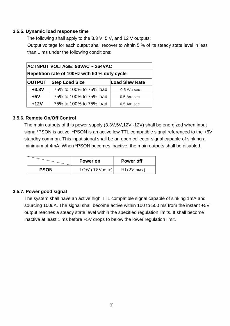
3.5.5. Dynamic load response time
The following shall apply to the 3.3 V, 5 V, and 12 V outputs:
Output voltage for each output shall recover to within 5 % of its steady state level in less
than 1 ms under the following conditions:
AC INPUT VOLTAGE: 90VAC ~ 264VAC
Repetition rate of 100Hz with 50 % duty cycle
OUTPUT Step Load Size Load Slew Rate
+3.3V 75% to 100% to 75% load 0.5 A/u sec
+5V 75% to 100% to 75% load 0.5 A/u sec
+12V 75% to 100% to 75% load 0.5 A/u sec
3.5.6. Remote On/Off Control
The main outputs of this power supply (3.3V,5V,12V,-12V) shall be energized when input
signal*PSON is active. *PSON is an active low TTL compatible signal referenced to the +5V
standby common. This input signal shall be an open collector signal capable of sinking a
minimum of 4mA. When *PSON becomes inactive, the main outputs shall be disabled.
Power on Power off
PSON LOW (0.8V max) HI (2V max)
3.5.7. Power good signal
The system shall have an active high TTL compatible signal capable of sinking 1mA and
sourcing 100uA. The signal shall become active within 100 to 500 ms from the instant +5V
output reaches a steady state level within the specified regulation limits. It shall become
inactive at least 1 ms before +5V drops to below the lower regulation limit.

⑧
3.6. PROTECTION
3.6.1. Over voltage protection
OUTPUT Min Max
+3.3V 3.75V 4.3V
+5V 5.7V 6.9V
+12V 13V 14.3V
3.6.2. Over power protection
OVER 110% ~ 150% of rated load Shut down latch off.
3.6.3. Short circuit protection
All output equipped with short circuit.(Shut down o/p voltage, re-power on to recover).
3.6.4. Over temperature protection When power supply temperature over 115±5℃, power supply will shut down
As it cools down to 85±5℃, the power supply will re-start in auto-recovery.
3.7. Power system fault signal
When one of the power supply module in the system fails to provide output, the system
shall provide:
3.7.1. Audible buzzer
When the warning buzzer sounds, the user can reset the warning buzzer by
pressing the buzzer reset or use the reset switch of the system chassis. The reset
switch can be connected by wires lead provided from the power supply system
(please refer to Sec. 3.7.2./3.7.3.). Insert the power module which is removed for
testing earlier, the sound of the warning buzzer will disappear, the external warning
LED will turn Green again. The LED indicating the status of the power supply will
light again when testing another power supply by performing the similar
procedure.

⑨
3.7.2. Buzzer status
POWER SUPPLY CONDITION Buzzer status
No AC power to all PSU OFF
AC present/Only Standby Output On OFF
Power supply DC outputs ON and OK OFF
Power supply failure Beeping
3.7.3. LED indicator status
3.7.4. TTL signal
POWER SUPPLY CONDITION OUTPUT CONDITION
NORMAL HIGH
FAILURE LOW
3.8 Load sharing
3.8.1. Forced Load Sharing
The +3.3V, +5V and +12V outputs shall have forced load sharing. The corresponding output
shall share within 5% at full load when operated in a redundant 1+1 configuration. The 5VSB
and –12V outputs shall not have forced load sharing between power modules.
Example of load share accuracy: Power supply #1 = 20A
Power supply #2 > 19A and < 21A
3.8.2. Load Sharing Signal
The power supplies load share shall use a single load share bus signal connected between
each corresponding output. If the load sharing is disabled by shorting the bus to ground, the
power system shall continue to operate within regulation limits for loads less than or equal to
the full load rating of each power supply. The failure of one power supply shall not effect the
output voltages of the other supply still operating.
POWER SUPPLY CONDITION Power system
status
Per Power Module
status
LED COLOR RED GREEN ORANGE
No AC power to all PSU OFF OFF OFF
AC present/Only Standby Output On ON OFF OFF
Power supply DC outputs ON and OK OFF ON ON
Power supply failure OFF Blinking OFF

⑩
3.9 Hot-swap procedures
Please refer to the following when either power module or the fan found
defective.
A) Locate the defective power module by examining the individual LED (if LED
without light, it indicates the power module is defective).
WARNING: Please perform the above step carefully otherwise i t may cause shut down the
whole system.
WARNING: Please do not remove the defective power module unt il you have worn gloves to
keep from be burned. This is due to the cover of th e power module is used as heat
sink for cooling, usually the temperature is around 50 ~ 60 degree Celsius under
full load condition.
B) Loosen the bracket screws of the power module
C) Remove the defective power module by pulling out method
WARNING:
Please put aside the power module await for cooling down. Keep from other
people tough it until it is cool.
D) Replace a new Good power module, insert the power module into the power
system to the end.
E) Check the LED of the power module light Green.
F) Check the LED indicating the total power system status. It should be from
twinkle to Green.
G) Tighten the screws of the power module to fix it.
⑪
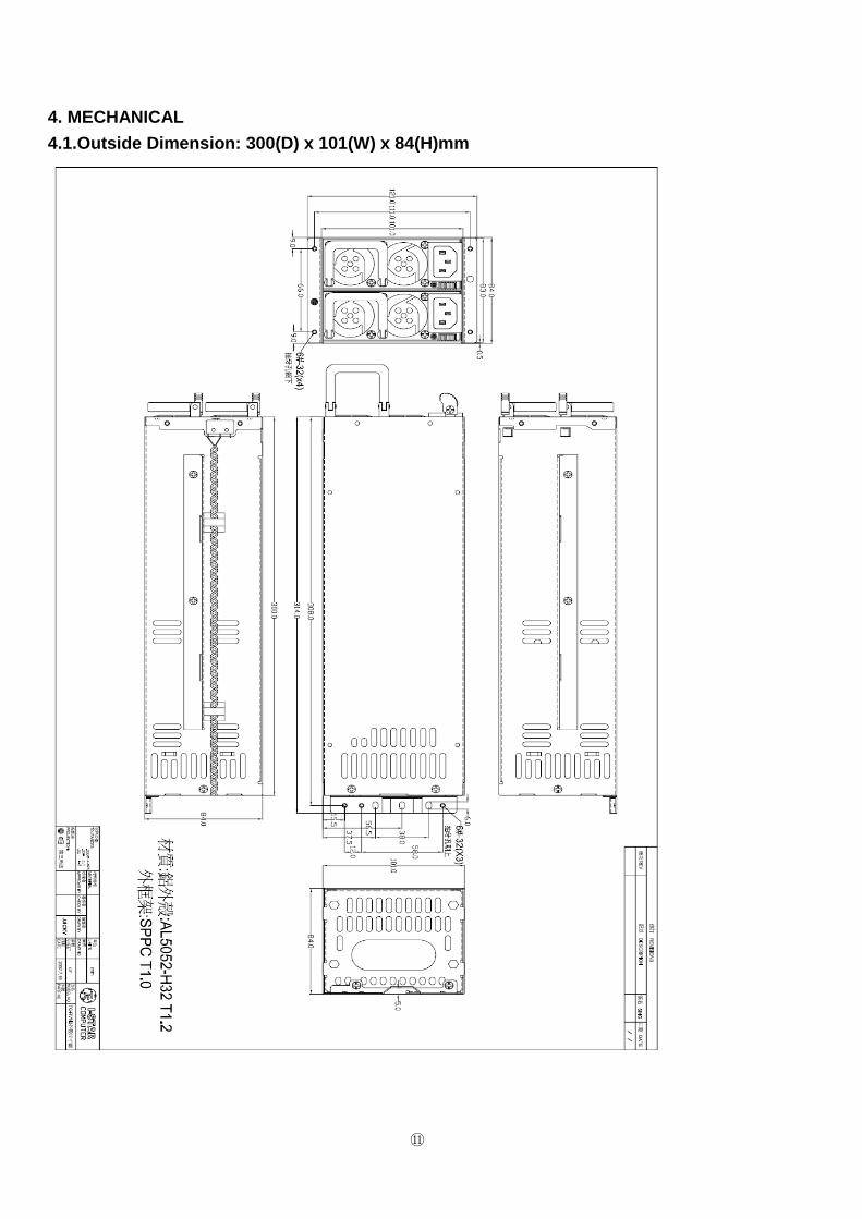
4. MECHANICAL
4.1.Outside Dimension: 300(D) x 101(W) x 84(H)mm

⑫
4.2. DC Output cables -- M24P+M8P+M4P, SATA*2, PCI- E 6pin*2, HDD*18, Floppy*2.
Below output harness length start from PCB boar d.
BLACK
ORANGE
YELLOWYELLOW
Connector HOUSING: MOLEX 39-01-0280 or equivalent
Pin8Pin4
8Pins(EPS12V)
Pin1 Pin5
PURPLE
PIN24PIN10
Connector HOUSING: MOLEX 39-01-2240 or equivalent
GRAYBLACKRED
BLACK
LENGTHWIRETYPE
SIGNAL WIRECOLOR
PinNo.
RED
ORANGEORANGE
PIN1 PIN13
10
1211
+12V3+12V3+3.3V
6
87
9
+5VCOMPW-OK+5SB
COM+5VCOM+3.3V
5
+3.3V
34
21
650mm ±20mm
14
1615
17
-12VCOM
PS-ONCOM
+3.3V13
COM1819 COM
+5V2120 OPTION
22 +5V+5V23
24 COM
NC
ORANGE
BLUE
RED
REDRED
GREEN
BLACK
BLACKBLACKBLACK
BLACK
ORANGE +3.3S
18AWG18AWG18AWG
18AWG18AWG18AWG
18AWG18AWG18AWG
18AWG
18AWG18AWG18AWG
22AWG
18AWG18AWG18AWG
18AWG18AWG18AWG
18AWG18AWG18AWG
18AWG18AWG
18AWG
18AWG
18AWG18AWG18AWG
18AWG18AWG18AWG1
2
43
5
COM
+12V78
6
PinNo.
WIRECOLOR
SIGNAL WIRETYPE
LENGTH
BLACKBLACK
650mm ±20mm
BLACKBLACK
YELLOW
YELLOWYELLOWYELLOW
COMCOM
COM+12V
+12V
+12V
24Pins(EPS12V)
TERMINAL: MOLEX 39-00-0039 or equivalent
TERMINAL: MOLEX 39-00-0060 or equivalent
PIN4PIN2PIN1 PIN3
COMCOMBLACK
650mm ±20mm
LENGTHWIRETYPESIGNAL
WIRECOLOR
PinNo.
34
21 18AWG
18AWG18AWG
18AWG
BLACK
YELLOW +12VYELLOW +12V
4Pins(ATX12V,FOR P4)Connector HOUSING: MOLEX 39-01-0280 or equivalentTERMINAL: MOLEX 39-00-0060 or equivalent

⑬
P4H1P4H3P4H6
P4H5P4H4P4H2
TERMINAL:AMP 60619-4 or equivalent
4Pins(HD/CD-ROM/RW)
COM150mm ±10mm
LENGTHWIRESIZESIGNAL
WIRECOLOR
PinNo.
34
21 18AWG
18AWG18AWG
18AWG
BLACK
RED
+12VYELLOW
BLACK COM
+5V
Connector HOUSING: AMP 480424-0 or equivalent
Name
P4F2P4F1
P4H6
P4H5
P4H4
P4H3
P4H2
P4F2
P4H1
P4F1
PIN4PIN3PIN2PIN1
PIN1PIN2PIN3PIN4
PIN4PIN3PIN2PIN1
PIN1PIN2PIN3PIN4
PIN4PIN3PIN2PIN1
PIN1PIN2PIN3PIN4
PIN1PIN4
PIN1PIN4
Name
Name
Connector HOUSING: AMP 480424-0 or equivalent
Connector HOUSING: AMP 171822-4 or equivalent
COM150mm ±10mm
LENGTHWIRETYPESIGNAL
WIRECOLOR
PinNo.
34
21 22AWG
22AWG22AWG
22AWG
BLACK
RED
+12VYELLOW
BLACK COM+5V
+5V
COMBLACK
YELLOW +12V
RED
BLACK
18AWG
18AWG18AWG18AWG1
2
43
PinNo.
WIRECOLOR SIGNAL
WIRESIZE LENGTH
650mm ±20mmCOM
4Pins(FLOPPY DISK)
TERMINAL: AMP 170262-2 or equivalent
4Pins(HD/CD-ROM/RW)
TERMINAL:AMP 60619-4 or equivalent
TERMINAL: MOLEX 39-00-0060 or equivalentConnector HOUSING: MOLEX 39-01-0280 or equivalent6Pins(PCI Express)
+12V+12V
COMCOMCOM
YELLOWYELLOW
BLACKBLACK
BLACK
+12VYELLOW
18AWG18AWG18AWG
18AWG18AWG18AWG1
2
43
56
PinNo.
WIRECOLOR SIGNAL
WIRETYPE LENGTH
650mm ±20mm
PIN1 PIN4
PIN3 PIN6

⑭
/ WHITE
/ WHITE
H2510
GREENPWR LED
RED
BROWN5 LED
PIN2PIN1
187P
/ WHITE
WIRE COLORName
PW1 LED
PW2 LED
2510
COM900mm ±20mm
LENGTHWIRETYPESIGNAL
WIRECOLOR
PinNo.
21 22AWG
22AWG
BLACK+5VRED
900mm ±20mm
LENGTHWIRETYPE
22AWG
22AWG
22AWG
22AWG22AWG1
2
PinNo.
WIRECOLOR SIGNAL
WIRETYPE LENGTH
900mm ±20mmGRAYGRAY
LED COLOR
ORANGE
RED/GREEN
COMREST
Connector HOUSING: Molex 22-01-3027 or equivalentTTL Signal
ALARM Rest
LED Indicators Power Module (PW1/PW2 LED) & Power System (PWR LED)
PIN1
5PIN(SERIAL ATA HD) Connector HOUSING: TKP/H127M2 or equivalent
BLACK COM
YELLOW
18AWG18AWG1
2
PinNo.
WIRECOLOR SIGNAL
WIRETYPE LENGTH
650mm ±20mm150mm ±10mm
+12V
3 18AWG+5VREDBLACK COM 18AWG4
5 18AWG
+3.3VORANGE
ORANGE
PIN2PIN1

⑮
4.3. AC input connector
IEC 320 AC Inlet with EMI Filter, 15A/250V
4.4. Cooling
BY BALL BEARING DC FAN.
5. ENVIRONMENTS
5.1. Temperature
Operating : 0 to ℃ +45℃
Non Operating: -20 to ℃ +70℃
5.2. Humidity
Operating : 5% to 95%, non-condensing
Non Operating: 20% to 90%,non-condensing
5.3. Altitude
Operating: sea level to 7,000 feet
Non-operating: sea level to 40,000 feet
5.4. Shock
5.4.1. Operating
5g for 11ms with a ½ sine wave for each of the perpendicular axes X, Y, and Z.
5.4.2. Non-operating
30g for 11ms with a ½ sine wave for each of the perpendicular axes X, Y, and Z.
5.5. Vibration
5.5.1. Operating
10Hz to 500Hz sweep at 0.5g constant acceleration for one hour on each of the
perpendicular axes X, Y, and Z.
5.5.2. Non-operating
10Hz to 300Hz sweep at 2g constant acceleration for one hour on each of the
perpendicular axes X, Y, and Z.

⑯
5.6. Power line disturbance
5.6.1. Over voltage
The power supply shall function with no interruption when line input is surged 15 %
above nominal for one second. The verification test shall be performed 10 times with a
10 % duty cycle.
5.6.2. Under voltage
The power supply shall function with no interruption when line input is sagged
20%below nominal for one second. The verification test shall be performed10 times
with a 10 % duty cycle.
5.6.3. Surviving surge and sag
Power supply shall survive a surge to 147VAC for 0.5 second and a sag to 80VAC
for 0.5 second without damage.
6. REGULATORY
6.1. Safety standards
A. UL/cUL60950-1
B. TUV EN60950-1
C. CB
D. CCC
6.1.1. Leakage current
Input leakage current from line to frame ground will be less than 3.5mA rms. for
each power module. Condition: 264Vac/60Hz
6.1.2. Isolation resistance
Primary to earth ground 500Vdc , 50M ohms Min.
6.1.3. Dielectric Withstand Voltage
Primary to Secondary : 1500V ac / 50Hz for 1 Minute.
Primary to Safety Ground: 1500V ac / 50Hz for 1 Minute.
6.2. Electromagnetic compatibility
6.2.1. EMI/RFI standards
A. FCC Part 15, class A.
B. CISPR22 (EN55022)class A.

⑰
6.2.2. Line noise disturbance
The power supply shall operate normally when installed in a computer system and subjected
to power line noise described in EN61000-4-4, level 3 (2 kV open circuit voltage). The power
supply shall not cause any failure in the host computer system during line noise testing.
6.2.3. AC line transients
The power supply shall comply with the surge voltage requirements of EN61000-4-5 level 3
(2 kV peak open circuit voltage from line/neutral to GND , and 1 kV from line to neutral)
7. Reliability
7.1. Mean Time Between Failure(MTBF) Using MIL - HDBK -217F the calculated MTBF>100,000 hours at 25℃.
*Note:
The description stated herein is subject to change without prior notice.