62-2021 03 - occupancy sensor covers for tb7200/ tb7300 ... · infrared (pir) motion detector with...
TRANSCRIPT
INSTALLATION INSTRUCTIONS
62-2021-03
Occupancy Sensor Covers for TB7200/ TB7300/ TB7600 Series Communicating Thermostats
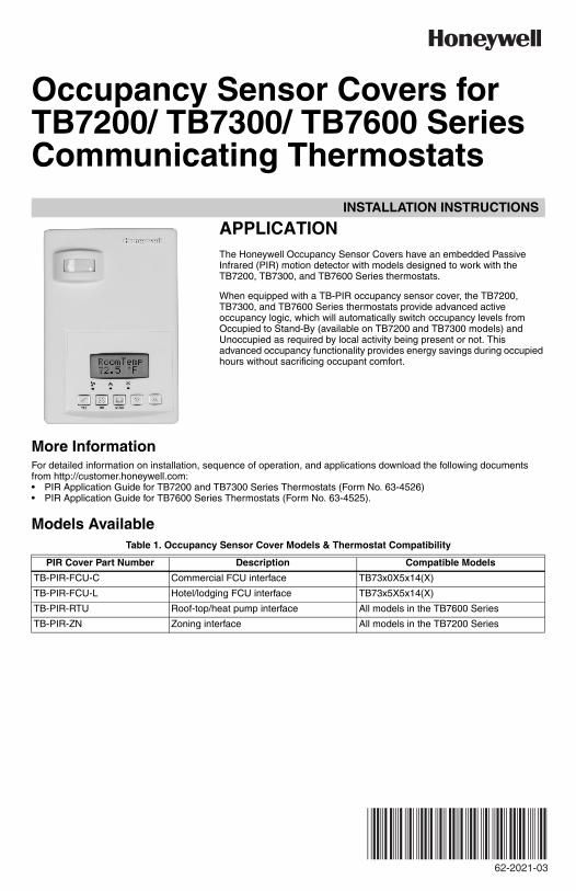
APPLICATIONThe Honeywell Occupancy Sensor Covers have an embedded Passive Infrared (PIR) motion detector with models designed to work with the TB7200, TB7300, and TB7600 Series thermostats.
When equipped with a TB-PIR occupancy sensor cover, the TB7200, TB7300, and TB7600 Series thermostats provide advanced active occupancy logic, which will automatically switch occupancy levels from Occupied to Stand-By (available on TB7200 and TB7300 models) and Unoccupied as required by local activity being present or not. This advanced occupancy functionality provides energy savings during occupied hours without sacrificing occupant comfort.
More InformationFor detailed information on installation, sequence of operation, and applications download the following documents from http://customer.honeywell.com:• PIR Application Guide for TB7200 and TB7300 Series Thermostats (Form No. 63-4526)• PIR Application Guide for TB7600 Series Thermostats (Form No. 63-4525).
Models AvailableTable 1. Occupancy Sensor Cover Models & Thermostat Compatibility
PIR Cover Part Number Description Compatible Models
TB-PIR-FCU-C Commercial FCU interface TB73x0X5x14(X)
TB-PIR-FCU-L Hotel/lodging FCU interface TB73x5X5x14(X)
TB-PIR-RTU Roof-top/heat pump interface All models in the TB7600 Series
TB-PIR-ZN Zoning interface All models in the TB7200 Series
OCCUPANCY SENSOR COVERS FOR TB7200/ TB7300/ TB7600 SERIES COMMUNICATING THERMOSTATS
62-2021—03 2
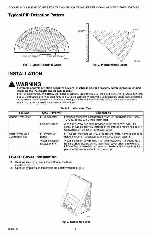
Typical PIR Detection Pattern
INSTALLATION
WARNINGElectronic controls are static sensitive devices. Discharge yourself properly before manipulation and installing the thermostat and its accessories.Short circuit or wrong wiring may permanently damage the thermostat or the equipment. All TB7200/7300/7600 Series thermostats are to be used only as operating controls. Whenever a control failure could lead to personal injury and/or loss of property, it becomes the responsibility of the user to add safety devices and/or alarm system to protect against such catastrophic failures.
Table 2. Installation Tips
TB-PIR Cover Installation1. Remove security screw on the bottom of the ther-
mostat cover. 2. Open up by pulling on the bottom side of thermostat. (Fig. 3)
Fig. 3. Removing cover.
Fig. 1. Typical Horizontal Angle Fig. 2. Typical Vertical Angle
Tip Type Area Of Interest Explanation
General Installation PIR Connector Polarized connector is located at bottom left hand corner of TB7200, TB7300, or TB7600 Series thermostat
Security Screw A security screw has been provided in the thermostat box. This screw should be carefully installed in the intended mounting position located bottom center of thermostat cover.
Initial Power Up & Commissioning
PIR Warm up period
PIR Sensor may take up-to 60 seconds after initial warm up period to detect movement consistent with typical detection pattern.
Visual indication (Status of PIR)
Visual indication of PIR activity for commissioning is provided via a blinking LEDs located on the thermostat cover under the PIR lens. LEDs will be active while occupant is in field of detection pattern for a period of 30 minutes after initial power up.
15°
15° 15°
15°
60° 60°
ZONE NOT RELIABLE ZONE NOT RELIABLE
0°
M21308
45°
20 FEETCENTER
M21309
°C°F
M21300
OCCUPANCY SENSOR COVERS FOR TB7200/ TB7300/ TB7600 SERIES COMMUNICATING THERMOSTATS
3 62-2021—03
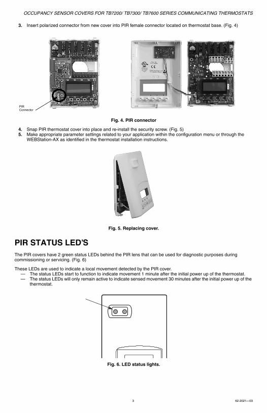
3. Insert polarized connector from new cover into PIR female connector located on thermostat base. (Fig. 4)
Fig. 4. PIR connector
4. Snap PIR thermostat cover into place and re-install the security screw. (Fig. 5)5. Make appropriate parameter settings related to your application within the configuration menu or through the
WEBStation-AX as identified in the thermostat installation instructions.
Fig. 5. Replacing cover.
PIR STATUS LED’SThe PIR covers have 2 green status LEDs behind the PIR lens that can be used for diagnostic purposes during commissioning or servicing. (Fig. 6)
These LEDs are used to indicate a local movement detected by the PIR cover. — The status LEDs start to function to indicate movement 1 minute after the initial power up of the thermostat.— The status LEDs will only remain active to indicate sensed movement 30 minutes after the initial power up of the
thermostat.
Fig. 6. LED status lights.
PIRConnector
OCCUPANCY SENSOR COVERS FOR TB7200/ TB7300/ TB7600 SERIES COMMUNICATING THERMOSTATS
Automation and Control SolutionsHoneywell International Inc.
1985 Douglas Drive North
Golden Valley, MN 55422
customer.honeywell.com
® U.S. Registered Trademark© 2011 Honeywell International Inc.62-2021—03 M.S. Rev. 09-11 Printed in United States
SPECIFICATIONSPIR cover power requirements: 5 Vdc max current draw of 7mA
Operating conditions: 0 C to 50 C (32 F to 122 F); 0% to 95% R.H. non-condensing
Storage conditions: -30 C to 50 C (-22 F to 122 F); 0% to 95% R.H. non-condensing
Sensor: Local Passive Infrared Sensor
Dimensions: 4.94 in. x 3.38 in. x 1.0 in.
Approximate shipping weight: 0.1 lb
Agency Approvals: UL: UL 873 (US) and CSA C22.2 No. 24 (Canada), File E27734 with CCN XAPX (US) and XAPX7 (Canada)FCC: Compliant to CFR 47, Part 15, Subpart B, Class A (US)Industry Canada: ICES-003 (Canada)CE: EMC Directive 89/336/EEC (Europe Union)