620 mobile piston pump catalog ady074 design code apub/@eaton/@hyd/...2 eato mobile piston pump...
TRANSCRIPT
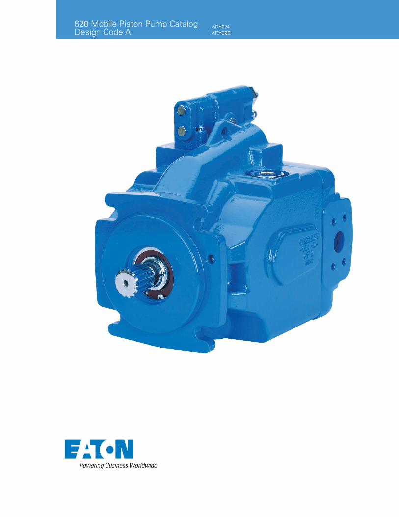
620 Mobile Piston Pump Catalog Design Code A
ADY074ADY098
2 EATON 620 Mobile Piston Pump Catalog E-PUPI-TM017-E5 March 2017
Introduction
620 Series Piston Pump
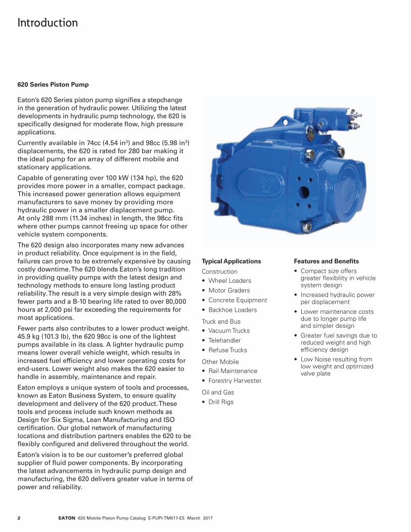
Eaton’s 620 Series piston pump signifies a stepchange in the generation of hydraulic power. Utilizing the latest developments in hydraulic pump technology, the 620 is specifically designed for moderate flow, high pressure applications.
Currently available in 74cc (4.54 in3) and 98cc (5.98 in3) displacements, the 620 is rated for 280 bar making it the ideal pump for an array of different mobile and stationary applications.
Capable of generating over 100 kW (134 hp), the 620 provides more power in a smaller, compact package. This increased power generation allows equipment manufacturers to save money by providing more hydraulic power in a smaller displacement pump. At only 288 mm (11.34 inches) in length, the 98cc fits where other pumps cannot freeing up space for other vehicle system components.
The 620 design also incorporates many new advances in product reliability. Once equipment is in the field, failures can prove to be extremely expensive by causing costly downtime. The 620 blends Eaton’s long tradition in providing quality pumps with the latest design and technology methods to ensure long lasting product reliability. The result is a very simple design with 28% fewer parts and a B-10 bearing life rated to over 80,000 hours at 2,000 psi far exceeding the requirements for most applications.
Fewer parts also contributes to a lower product weight. 45.9 kg (101.3 lb), the 620 98cc is one of the lightest pumps available in its class. A lighter hydraulic pump means lower overall vehicle weight, which results in increased fuel efficiency and lower operating costs for end-users. Lower weight also makes the 620 easier to handle in assembly, maintenance and repair.
Eaton employs a unique system of tools and processes, known as Eaton Business System, to ensure quality development and delivery of the 620 product. These tools and process include such known methods as Design for Six Sigma, Lean Manufacturing and ISO certification. Our global network of manufacturing locations and distribution partners enables the 620 to be flexibly configured and delivered throughout the world.
Eaton’s vision is to be our customer’s preferred global supplier of fluid power components. By incorporating the latest advancements in hydraulic pump design and manufacturing, the 620 delivers greater value in terms of power and reliability.
Typical Applications
Construction• Wheel Loaders
• Motor Graders
• Concrete Equipment
• Backhoe Loaders
Truck and Bus• Vacuum Trucks
• Telehandler
• Refuse Trucks
Other Mobile• Rail Maintenance
• Forestry Harvester
Oil and Gas
• Drill Rigs
Features and Benefits
• Compact size offers greater flexibility in vehicle system design
• Increased hydraulic power per displacement
• Lower maintenance costs due to longer pump life and simpler design
• Greater fuel savings due to reduced weight and high efficiency design
• Low Noise resulting from low weight and optimized valve plate
3EATON 620 Mobile Piston Pump Catalog E-PUPI-TM017-E5 March 2017
Table of Contents
Model Codes 4Specifications and Performance 6
Control OptionsLoad Sense and Pressure Compensator 7Pressure Compensator 8EH Inverse Proportional Pressure Control (IPPC) 9Remote Pressure Control 10Electronic Destroke Valve 11
Performance ADY074 12ADY098 16
Pump InstallationADY074 C-Mount – Side-Ported 20ADY074 C-Mount - Rear-Ported 21ADY074 Thru-Drive SAE A Option 22ADY074 Thru-Drive SAE B Option 23ADY074 Thru-Drive SAE C Option 24ADY098 C-Mount – Side-Ported 25ADY098 C-Mount - Rear-Ported 26ADY098 Thru-Drive SAE A Option 27ADY098 Thru-Drive SAE B Option 28ADY098 Thru-Drive SAE C Option 29
Control InstallationPressure Compensator 30Load Sense and Pressure Compensator 31EH Inverse Proportional Pressure Control (IPPC) 32Electronic Destroke Valve 33
External Manual Stroke Adjustment 34Input Shaft Options 35Center of Gravity 37
Installation and Start-up 38
4 EATON 620 Mobile Piston Pump Catalog E-PUPI-TM017-E5 March 2017
Model Codes620 Mobile Piston Pump
1 2 3 Pump SeriesADY – 620 Series Open
Circuit Piston Pump
4 5 6 Pump Displacement074 – 74.4 cm3/r [4.54 in3/r]098 – 98.0 cm3/r [5.98 in3/r]
7 Input Shaft RotationR – Right HandL – Left Hand
8 9 Front Mount and Shaft
05 – 4 Bolt C, 31.8 mm (1.25) Dia. Keyed Shaft
06 – 4 Bolt C, 14 Tooth 12/24 Spline
07 – 4 Bolt C, 38.1 (1.50 in) Dia Straight Keyed
08 – 4 Bolt C, 17 Tooth 12/24 Spline
10 – 4 Bolt C, 31.8 mm (1.25 in) Dia. Tapered Keyed Shaft
10 11 Main Ports Size & Location
AA – 098 Rear Ports, Suction 2.5” (Code 61), Pressure 1” (Code 61).
AB – 098 Side Ports Suction - 2.5” (Code 61); Pressure - 1” (Code 61)
AC – 098 Rear Ports, Suction 2.5” (Code 61), with M12 Threads, Pressure 1” (Code 61) with M10 Threads
AD – 098 Side Ports Suction - 2.5” (Code 61) with M12 Threads; Pressure - 1” (Code 61) with M10 Threads
AF – 074 Side Ports Suction - 2” (Code 61); Pressure - 1” (Code 61)
AG – 074 Rear Port, Suction 2”(Code 61) with M12 Threads, Pressure 1” (Code 61) with M10 Threads
AH – 074 Side Ports Suction - 2” (Code 61) with M12 Threads; Pressure - 1” (Code 61) with M10 Threads
AJ – 074 Rear Ports, Suction 2” (Code 61), Pressure 1” (Code 61)
12 Case Drain Ports1 – 1.3125 - 12 SAE O-Ring
- Top2 – 1.3125 - 12 SAE O-Ring
- Bottom 3 – M33 x 2.0 O-Ring - Top 4 – M33 x 2.0 O-Ring -
Bottom
13 Diagnostic Pressure Ports Not available on thru-drive units
0 – No Diagnostic Pressure Ports
1 – .5625 - 18 SAE O-Ring - Plugged (Rear Ports Only)
2 – M14 Plugged (Both rear and side)
14 Controller TypeA – Pressure Flow
Compensator with .4375 - 20 SAE O-Ring Load Sense Port
B – Pressure Flow Compensator with M14 Metric O-Ring Load Sense Port
C – Pressure Compensator Only
V – EH Inverse Proportional Pressure Control
W – Remote Pressure Control with .4375-20 SAE O-Ring Port, Left Side #
1 – Remote Pressure Control M12 Metric O-Ring Port, Left Side
15 16 Pressure Compensator Setting (Tolerance on Setting)*
08 – 76 - 84 bar (1102 - 1218 psi)
16 – 156 - 164 bar (2263 - 2379 psi)
20 – 196 - 204 bar (2843 - 2959 psi)
24 – 236 - 244 bar (3423 - 3539 psi)
28 – 276 - 284 bar (4003 - 4119 psi)
ADY 098 R 05 AB 1 0 A 28 20 00 00 1 00 1 00 CD 0 A
1 7 12 13 14 21 22 23 262 3 4 5 6 8 9 10 11 15 16 17 18 323129 3027 2824 2519 20
* Additional Settings Available by Request
# - Recommend RPC pressure settings 10-21 bar (140-350 psi)
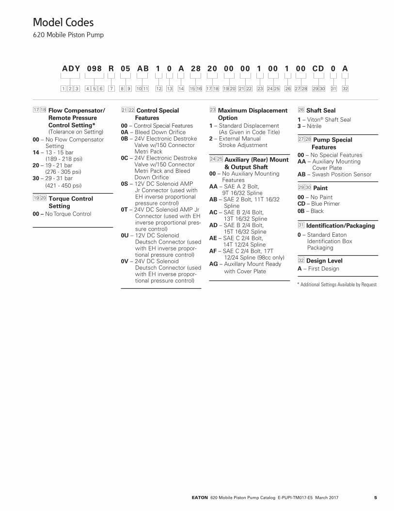
5EATON 620 Mobile Piston Pump Catalog E-PUPI-TM017-E5 March 2017
Model Codes620 Mobile Piston Pump
17 18 Flow Compensator/ Remote Pressure Control Setting* (Tolerance on Setting)
00 – No Flow Compensator Setting
14 – 13 - 15 bar (189 - 218 psi)
20 – 19 - 21 bar (276 - 305 psi)
30 – 29 - 31 bar (421 - 450 psi)
19 20 Torque Control Setting
00 – No Torque Control
21 22 Control Special Features
00 – Control Special Features0A – Bleed Down Orifice0B – 24V Electronic Destroke
Valve w/150 Connector Metri Pack
0C – 24V Electronic Destroke Valve w/150 Connector Metri Pack and Bleed Down Orifice
0S – 12V DC Solenoid AMP Jr Connector (used with EH inverse proportional pressure control)
0T – 24V DC Solenoid AMP Jr Connector (used with EH inverse proportional pres-sure control)
0U – 12V DC Solenoid Deutsch Connector (used with EH inverse propor-tional pressure control)
0V – 24V DC Solenoid Deutsch Connector (used with EH inverse propor-tional pressure control)
23 Maximum Displacement Option
1 – Standard Displacement (As Given in Code Title)
2 – External Manual Stroke Adjustment
24 25 Auxiliary (Rear) Mount & Output Shaft
00 – No Auxiliary Mounting Features
AA – SAE A 2 Bolt, 9T 16/32 Spline
AB – SAE 2 Bolt, 11T 16/32 SplineAC – SAE B 2/4 Bolt,
13T 16/32 SplineAD – SAE B 2/4 Bolt,
15T 16/32 SplineAE – SAE C 2/4 Bolt,
14T 12/24 SplineAF – SAE C 2/4 Bolt, 17T 12/24 Spline (98cc only)AG – Auxillary Mount Ready
with Cover Plate
26 Shaft Seal1 – Viton® Shaft Seal3 – Nitrile
27 28 Pump Special Features
00 – No Special FeaturesAA – Auxiliary Mounting
Cover PlateAB – Swash Position Sensor
29 30 Paint00 – No PaintCD – Blue Primer0B – Black
31 Identification/Packaging0 – Standard Eaton
Identification Box Packaging
32 Design LevelA – First Design
ADY 098 R 05 AB 1 0 A 28 20 00 00 1 00 1 00 CD 0 A
1 7 12 13 14 21 22 23 262 3 4 5 6 8 9 10 11 15 16 17 18 323129 3027 2824 2519 20
* Additional Settings Available by Request

6 EATON 620 Mobile Piston Pump Catalog E-PUPI-TM017-E5 March 2017
Specifications and Performance
Inlet Pressure, Case Pressure, and Operating Temperature RequirementsInlet Pressure Case Pressure Operating Temperature Maximum Maximum Minimum MaximumRated Minimum Maximum Continuous Intermittent Peak Rated Temperature Intermittentbar abs (psig) bar abs (in. Hg) bar abs (psig) bar abs (psig) bar abs (psig) bar abs (psig) °C (°F) °C (°F) °C (°F)1.0 (0) 0.85 (5) 4.4 (50) 1.3 (5) 3.1 (30) 6.2 (75) 93 (200) -25 (-13) 104 (220)
Hydraulic Fluids Recommended Minimum Viscosity @ Max. Operating Maximum Maximum Viscosity Intermittent Temperature of Minimum Viscosity Range Continuous at Startup 93°C (200°F) IntermittentFluid cSt (SUS) cSt (SUS) cSt (SUS) cSt (SUS) cSt (SUS)
Use antiwear hydraulic oil, 16 to 40 (80 to 188) 430 (1192) 2100 (9720) 10 (59) 6 (46)or automotive type crankcaseoil (designations SC, SD, SEor SF) per SAE J183 FEB80
For more information, see Eaton publication 579. For operation on other alternative or environmentally friendly fluids, please contact your Eaton Representative.
General Performance Specifications Units ADY074 ADY098 Displacement cc/r (in3/r) 74.4 (4.54) 98.0 (5.98)Weight1 kg (lbf) 43.5 (96.1) 45.9 (101.3)Pressure2 Continuous bar (psi) 280 (4060) 280 (4060) Intermittent3 320 (4600) 320 (4600) Peak4 350 (5000) 350 (5000)Speed5 Rated rpm 2400 2200 Max 2880 2640 Min 600 600Power Max (theoretical) kW (hp) 83.3 (111.7) 100.6 (134.9) Standby 2.1 (2.8) 2.6 (3.5)Torque Max (theoretical) Nm (lb-ft) 331.5 (244.5) 436.7 (322.1)Bearing Life6 At 140 bar (2030 psi) B10 Hours 125,200 81,400 At 210 bar (3045 psi) 32,900 21,400 At 280 bar (4060 psi) 12,100 7,900Mass Moment of Inertia kg-m2 0.0089 0.0118 (lbm-ft2) (0.211) (0.279) 1 Standard SAE C non-through drive.2 The 620 is capable of running at higher pressures than shown. In order to not void the warranty, you must provide duty cycle information and receive written approval.3 Less than 10% of duty cycle. 4 Momentary system pressure spikes only. 5 Ratings based on Flange ports. Rated speed at 1 bar absolute [0 in Hg vac] inlet pressure and 100% displacement. For Max Speed see inlet pressure vs. speed charts. 6 Bearing life ratings at rated speed – 1 bar abs (0 psig) inlet. Will vary based on thrust and side loads. For additional information, contact EATON engineering
7EATON 620 Mobile Piston Pump Catalog E-PUPI-TM017-E5 March 2017
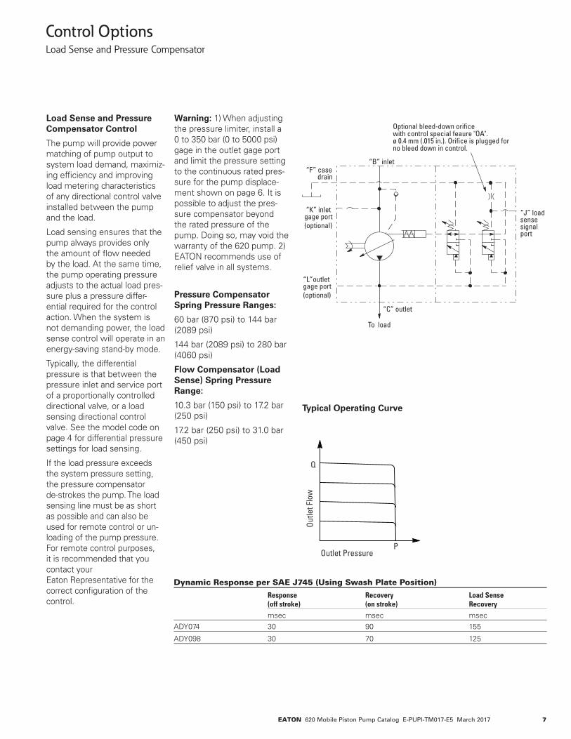
“B” inlet “F” case drain
“C” outlet
To load
“J” load sensesignal port
Optional bleed-down ori�ce with control special feaure "OA". ø 0.4 mm (.015 in.). Ori�ce is plugged for no bleed down in control.
“K” inlet gage port(optional)
“L”outlet gage port(optional)
Control OptionsLoad Sense and Pressure Compensator
Load Sense and Pressure Compensator Control
The pump will provide power matching of pump output to system load demand, maximiz-ing efficiency and improving load metering characteristics of any directional control valve installed between the pump and the load.
Load sensing ensures that the pump always provides only the amount of flow needed by the load. At the same time, the pump operating pressure adjusts to the actual load pres-sure plus a pressure differ-ential required for the control action. When the system is not demanding power, the load sense control will operate in an energy-saving stand-by mode.
Typically, the differential pressure is that between the pressure inlet and service port of a proportionally controlled directional valve, or a load sensing directional control valve. See the model code on page 4 for differential pressure settings for load sensing.
If the load pressure exceeds the system pressure setting, the pressure compensator de-strokes the pump. The load sensing line must be as short as possible and can also be used for remote control or un-loading of the pump pressure. For remote control purposes, it is recommended that you contact your Eaton Representative for the correct configuration of the control.
Typical Operating Curve
Dynamic Response per SAE J745 (Using Swash Plate Position)
Response Recovery Load Sense (off stroke) (on stroke) Recovery msec msec msecADY074 30 90 155
ADY098 30 70 125
Outlet Pressure
Outle
t Flo
w
Q
POutlet Pressure
Outle
t Flo
w
Q
P
Code C - Page 8Code A & B - Page 7
Warning: 1) When adjusting the pressure limiter, install a 0 to 350 bar (0 to 5000 psi) gage in the outlet gage port and limit the pressure setting to the continuous rated pres-sure for the pump displace-ment shown on page 6. It is possible to adjust the pres-sure compensator beyond the rated pressure of the pump. Doing so, may void the warranty of the 620 pump. 2) EATON recommends use of relief valve in all systems.
Pressure Compensator Spring Pressure Ranges:
60 bar (870 psi) to 144 bar (2089 psi)
144 bar (2089 psi) to 280 bar (4060 psi)
Flow Compensator (Load Sense) Spring Pressure Range:
10.3 bar (150 psi) to 17.2 bar (250 psi)
17.2 bar (250 psi) to 31.0 bar (450 psi)
8 EATON 620 Mobile Piston Pump Catalog E-PUPI-TM017-E5 March 2017
Control OptionsPressure Compensator
Pressure Compensator Control
The pump will provide a con-tinuously modulated flow to meet changing load demands at a pre-adjusted compensa-tor pressure. At pressures below the compensator set-ting, the pump will operate at maximum displacement. See model code on page 4 for compensator pressure ranges.
Warning: 1) When adjusting the pressure limiter, install a 0 to 350 bar (0 to 5000 psi) gage in the outlet gage port and limit the pressure setting to the continuous rated pressure for the pump displacement shown on page 6. It is possible to adjust the pressure compensator beyond the rated pressure of the pump. Doing so, may void the warranty of the 620 pump. 2) EATON recom-mends use of relief valve in all systems. Pressure Cut-off
Characteristics of Pressure Compensator Control @ 49°C (120°F), Static Conditions.
“K” Inlet Gage Port
“B” Inlet
“F” Case Drain
“C” Outlet
To Load
See Model Code on Page 4 for Spring (Pressure) Adjustment Ranges.
“K” Outlet Gage Port
Change in Pressure A
Outlet Pressure
Outle
t Flo
w Change
in Flow B
Q
P
+
+
Dynamic Response per SAE J745 (Using Swash Plate Position)
Response Recovery (off stroke) (on stroke)
msec msec
ADY074 30 90
ADY098 30 70
Outlet Pressure
Outle
t Flo
w
Q
POutlet Pressure
Outle
t Flo
w
Q
P
Code C - Page 8Code A & B - Page 7
Pressure Compensator Spring Pressure Ranges:
60 bar (870 psi) to 144 bar (2089 psi)144 bar (2089 psi) to 280 bar (4060 psi)
9EATON 620 Mobile Piston Pump Catalog E-PUPI-TM017-E5 March 2017
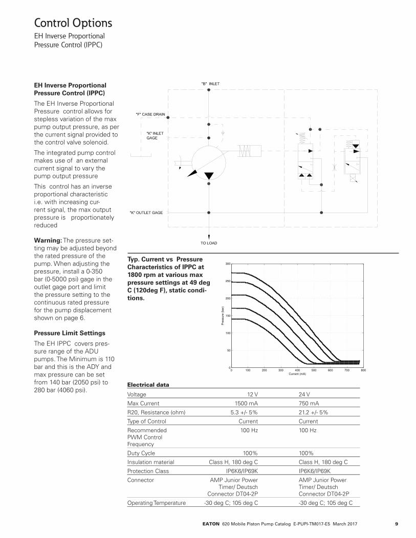
Control OptionsEH Inverse Proportional Pressure Control (IPPC)
EH Inverse Proportional Pressure Control (IPPC)
The EH Inverse Proportional Pressure control allows for stepless variation of the max pump output pressure, as per the current signal provided to the control valve solenoid.
The integrated pump control makes use of an external current signal to vary the pump output pressure
This control has an inverse proportional characteristic i.e. with increasing cur-rent signal, the max output pressure is proportionately reduced
Warning: The pressure set-ting may be adjusted beyond the rated pressure of the pump. When adjusting the pressure, install a 0-350 bar (0-5000 psi) gage in the outlet gage port and limit the pressure setting to the continuous rated pressure for the pump displacement shown on page 6.
Pressure Limit Settings
The EH IPPC covers pres-sure range of the ADU pumps. The Minimum is 110 bar and this is the ADY and max pressure can be set from 140 bar (2050 psi) to 280 bar (4060 psi).
Typ. Current vs Pressure Characteristics of IPPC at 1800 rpm at various max pressure settings at 49 deg C (120deg F), static condi-tions.
Electrical data
Voltage 12 V 24 V
Max Current 1500 mA 750 mA
R20, Resistance (ohm) 5.3 +/- 5% 21.2 +/- 5%
Type of Control Current Current
Recommended 100 Hz 100 Hz PWM Control Frequency
Duty Cycle 100% 100%
Insulation material Class H, 180 deg C Class H, 180 deg C
Protection Class IP6K6/IP69K IP6K6/IP69K
Connector AMP Junior Power AMP Junior Power Timer/ Deutsch Timer/ Deutsch Connector DT04-2P Connector DT04-2P
Operating Temperature -30 deg C; 105 deg C -30 deg C; 105 deg C
0 100 200 300 400 500 600 700 8000
50
100
150
200
250
300
Current (mA)
Pre
ssure
(bar)
10 EATON 620 Mobile Piston Pump Catalog E-PUPI-TM017-E5 March 2017
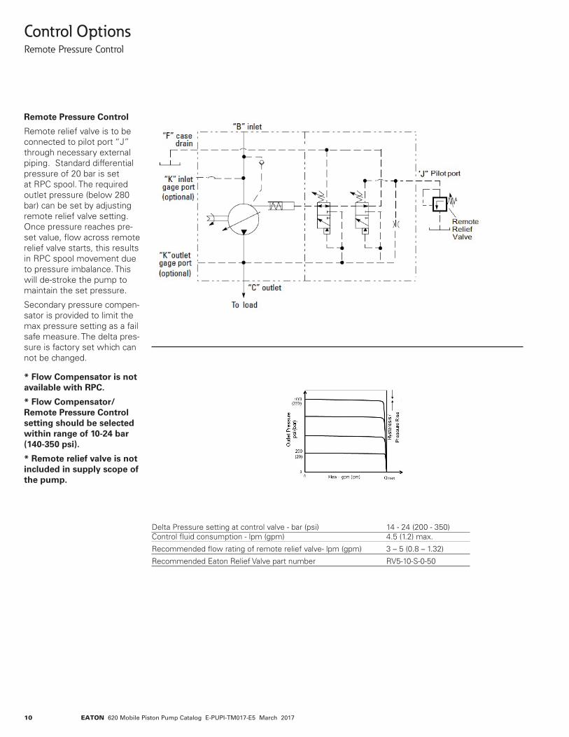
Control OptionsRemote Pressure Control
Remote Pressure Control
Remote relief valve is to be connected to pilot port “J” through necessary external piping. Standard differential pressure of 20 bar is set at RPC spool. The required outlet pressure (below 280 bar) can be set by adjusting remote relief valve setting. Once pressure reaches pre-set value, flow across remote relief valve starts, this results in RPC spool movement due to pressure imbalance. This will de-stroke the pump to maintain the set pressure.
Secondary pressure compen-sator is provided to limit the max pressure setting as a fail safe measure. The delta pres-sure is factory set which can not be changed.
* Flow Compensator is not available with RPC.
* Flow Compensator/ Remote Pressure Control setting should be selected within range of 10-24 bar (140-350 psi).
* Remote relief valve is not included in supply scope of the pump.
Delta Pressure setting at control valve - bar (psi) 14 - 24 (200 - 350) Control fluid consumption - lpm (gpm) 4.5 (1.2) max.
Recommended flow rating of remote relief valve- lpm (gpm) 3 – 5 (0.8 – 1.32)
Recommended Eaton Relief Valve part number RV5-10-S-0-50
11EATON 620 Mobile Piston Pump Catalog E-PUPI-TM017-E5 March 2017
“J” Load Sense Signal Port
“B” Inlet “F” Case Drain
“C” Outlet
To Load
Optional bleed down orifice with control special feature "0A". Ø 0.4mm (0.015 in). Orifice is plugged for no bleed down in control.
“K” Outlet Gage Port(Optional)
“K” Inlet Gage Port(Optional)
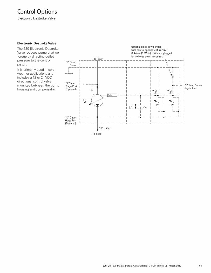
Control OptionsElectronic Destroke Valve
Electronic Destroke Valve
The 620 Electronic Destroke Valve reduces pump start-up torque by directing outlet pressure to the control piston.
It is primarily used in cold weather applications and includes a 12 or 24 VDC directional control valve mounted between the pump housing and compensator.
12 EATON 620 Mobile Piston Pump Catalog E-PUPI-TM017-E5 March 2017
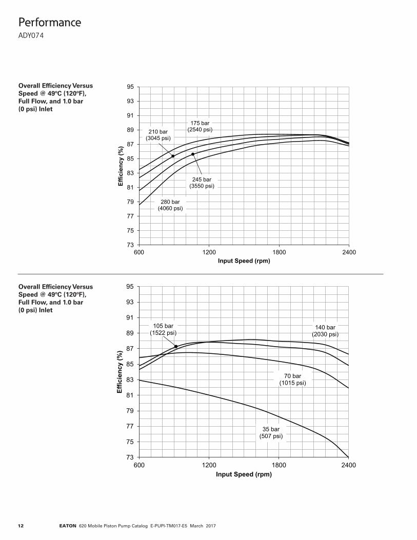
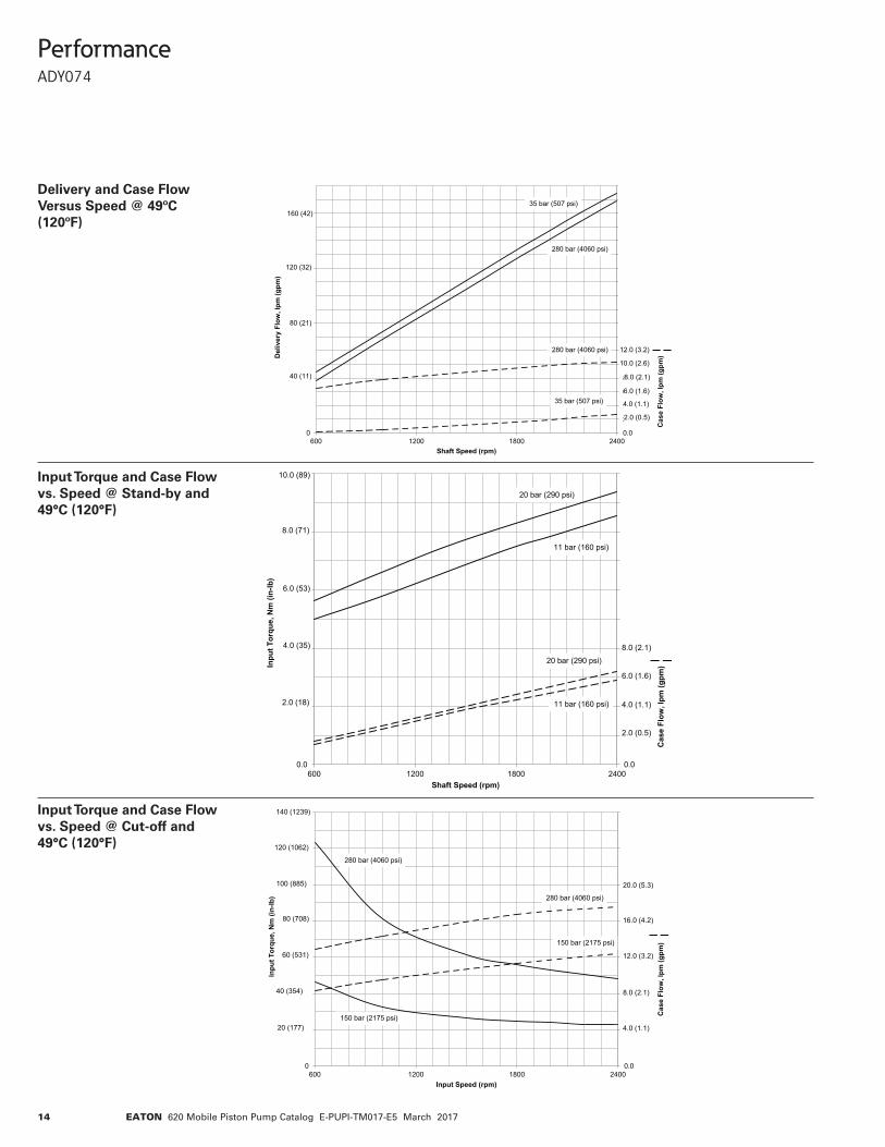
Performance ADY074
Overall Efficiency Versus Speed @ 49ºC (120ºF), Full Flow, and 1.0 bar (0 psi) Inlet
Overall Efficiency Versus Speed @ 49ºC (120ºF), Full Flow, and 1.0 bar (0 psi) Inlet
73
75
77
79
81
83
85
87
89
91
93
95
600 1200 1800 2400
Effic
ienc
y (%
)
Input Speed (rpm)
175 bar(2540 psi)
280 bar(4060 psi)
245 bar(3550 psi)
210 bar(3045 psi)
73
75
77
79
81
83
85
87
89
91
93
95
600 1200 1800 2400
Effic
ienc
y (%
)
Input Speed (rpm)
140 bar(2030 psi)
35 bar(507 psi)
70 bar(1015 psi)
105 bar(1522 psi)
13EATON 620 Mobile Piston Pump Catalog E-PUPI-TM017-E5 March 2017
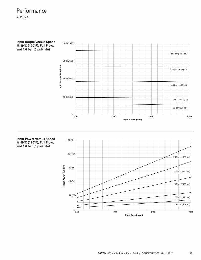
Performance ADY074
Input Torque Versus Speed @ 49ºC (120ºF), Full Flow, and 1.0 bar (0 psi) Inlet
Input Power Versus Speed @ 49ºC (120ºF), Full Flow, and 1.0 bar (0 psi) Inlet
0
20
40
60
80
100
600 1200 1800 2400
Inpu
t Pow
er, k
W (H
P)
Input Speed (rpm)
70 bar (1015 psi)
140 bar (2030 psi)
210 bar (3050 psi)
280 bar (4060 psi)
35 bar (507 psi)
20 (27)
40 (54)
60 (80)
80 (107)
100 (134)
0
100
200
300
400
600 1200 1800 2400
Inpu
t Tor
que,
Nm
(in-
lb)
Input Speed (rpm)
70 bar (1015 psi)
140 bar (2030 psi)
210 bar (3050 psi)
280 bar (4060 psi)
35 bar (507 psi)
400 (3540)
300 (2655)
300 (2655)
Inpu
t Tor
que,
Nm
(in-
lb)
100 (885)
14 EATON 620 Mobile Piston Pump Catalog E-PUPI-TM017-E5 March 2017
Performance ADY074
Delivery and Case Flow Versus Speed @ 49ºC (120ºF)
Input Torque and Case Flow vs. Speed @ Stand-by and 49°C (120°F)
Input Torque and Case Flow vs. Speed @ Cut-off and 49°C (120°F)
0.0
2.0
4.0
6.0
8.0
10.0
12.0
14.0
16.0
18.0
20.0
22.0
24.0
26.0
28.0
30.0
32.0
34.0
36.0
0
40
80
120
160
600 1200 1800 2400
Cas
e Fl
ow, l
pm (g
pm)D
eliv
ery
Flow
, lpm
(gpm
)
Shaft Speed (rpm)
40 (11)
80 (21)
120 (32)
160 (42)
2.0 (0.5)
4.0 (1.1)
6.0 (1.6)
8.0 (2.1)
10.0 (2.6)
12.0 (3.2)
35 bar (507 psi)
280 bar (4060 psi)
35 bar (507 psi)
280 bar (4060 psi)
0.0
2.0
4.0
6.0
8.0
10.0
12.0
14.0
16.0
18.0
20.0
0.0
2.0
4.0
6.0
8.0
10.0
600 1200 1800 2400
Cas
e Fl
ow, l
pm (g
pm)In
put T
orqu
e, N
m (i
n-lb
)
Shaft Speed (rpm)
2.0 (18)
4.0 (35)
6.0 (53)
8.0 (71)
10.0 (89)
2.0 (0.5)
4.0 (1.1)
6.0 (1.6)
8.0 (2.1)
20 bar (290 psi)
11 bar (160 psi)
20 bar (290 psi)
11 bar (160 psi)
0.0
4.0
8.0
12.0
16.0
20.0
24.0
28.0
0
20
40
60
80
100
120
140
600 1200 1800 2400
Cas
e Fl
ow, l
pm (g
pm)
Inpu
t Tor
que,
Nm
(in-
lb)
Input Speed (rpm)
280 bar (4060 psi)
150 bar (2175 psi)
280 bar (4060 psi)
150 bar (2175 psi)
20 (177)
40 (354)
60 (531)
80 (708)
100 (885)
120 (1062)
140 (1239)
4.0 (1.1)
8.0 (2.1)
12.0 (3.2)
16.0 (4.2)
20.0 (5.3)
15EATON 620 Mobile Piston Pump Catalog E-PUPI-TM017-E5 March 2017
Performance ADY074
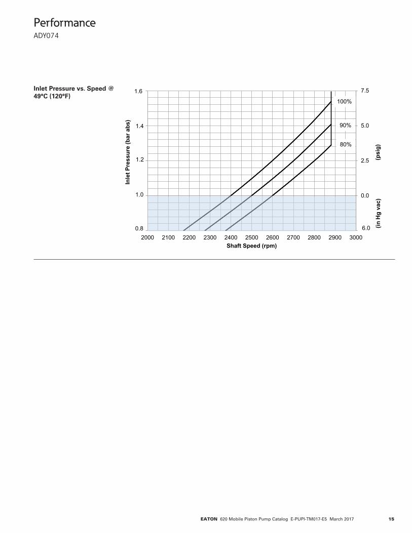
Inlet Pressure vs. Speed @ 49°C (120°F)
-2.5
0.0
2.5
5.0
7.5
-2.5
0.0
2.5
5.0
7.5
2000 2100 2200 2300 2400 2500 2600 2700 2800 2900 3000
(psi
g)
Inle
t Pre
ssur
e (b
ar a
bs)
Shaft Speed (rpm)
1.0
0.8
1.2
1.4
100%
90%
80%
6.0 (inH
g va
c)
1.6
16 EATON 620 Mobile Piston Pump Catalog E-PUPI-TM017-E5 March 2017
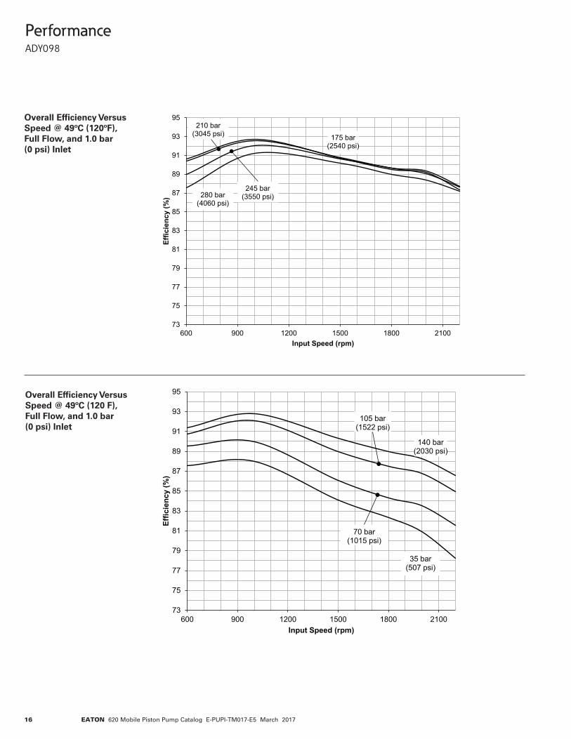
Performance ADY098
Overall Efficiency Versus Speed @ 49ºC (120ºF), Full Flow, and 1.0 bar (0 psi) Inlet
Overall Efficiency Versus Speed @ 49ºC (120 F), Full Flow, and 1.0 bar (0 psi) Inlet
73
75
77
79
81
83
85
87
89
91
93
95
600 900 1200 1500 1800 2100
Effic
ienc
y (%
)
Input Speed (rpm)
140 bar(2030 psi)
35 bar(507 psi)
70 bar(1015 psi)
105 bar(1522 psi)
73
75
77
79
81
83
85
87
89
91
93
95
600 900 1200 1500 1800 2100
Effic
ienc
y (%
)
Input Speed (rpm)
175 bar(2540 psi)
280 bar(4060 psi)
245 bar(3550 psi)
210 bar(3045 psi)
17EATON 620 Mobile Piston Pump Catalog E-PUPI-TM017-E5 March 2017
Performance ADY098
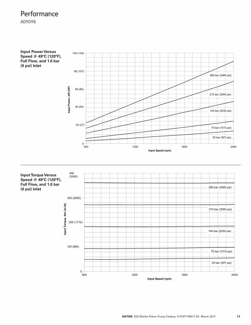
Input Torque Versus Speed @ 49ºC (120ºF), Full Flow, and 1.0 bar (0 psi) Inlet
Input Power Versus Speed @ 49ºC (120ºF), Full Flow, and 1.0 bar (0 psi) Inlet
0
20
40
60
80
100
600 1200 1800 2400
Inpu
t Pow
er, k
W (H
P)
Input Speed (rpm)
70 bar (1015 psi)
140 bar (2030 psi)
210 bar (3050 psi)
280 bar (4060 psi)
35 bar (507 psi)
20 (27)
40 (54)
60 (80)
80 (107)
100 (134)
0
100
200
300
400
600 1200 1800 2400
Inpu
t Tor
que,
Nm
(in-
lb)
Input Speed (rpm)
70 bar (1015 psi)
140 bar (2030 psi)
210 bar (3050 psi)
280 bar (4060 psi)
100 (885)
200 (1770)
300 (2655)
400 (3540)
35 bar (507 psi)
18 EATON 620 Mobile Piston Pump Catalog E-PUPI-TM017-E5 March 2017
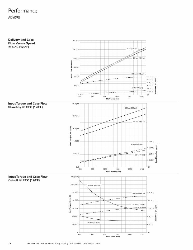
Performance ADY098
Input Torque and Case Flow Stand-by @ 49ºC (120ºF)
Input Torque and Case Flow Cut-off @ 49ºC (120ºF)
Delivery and Case Flow Versus Speed @ 49ºC (120ºF)
0.0
2.0
4.0
6.0
8.0
10.0
12.0
14.0
16.0
18.0
20.0
22.0
24.0
26.0
28.0
30.0
32.0
34.0
36.0
0
40
80
120
160
200
240
600 900 1200 1500 1800 2100
Cas
e Fl
ow, l
pm (g
pm)D
eliv
ery
Flow
, lpm
(gpm
)
Shaft Speed (rpm)
40 (11)
80 (21)
120 (32)
160 (42)
2.0 (0.5)
4.0 (1.1)
6.0 (1.6)
8.0 (2.1)
10.0 (2.6)
12.0 (3.2)
35 bar (507 psi)
280 bar (4060 psi)
35 bar (507 psi)
280 bar (4060 psi)
200 (53)
240 (63)
0.0
2.0
4.0
6.0
8.0
10.0
12.0
14.0
16.0
18.0
20.0
0.0
2.0
4.0
6.0
8.0
10.0
600 900 1200 1500 1800 2100
Cas
e Fl
ow, l
pm (g
pm)In
put T
orqu
e, N
m (i
n-lb
)
Shaft Speed (rpm)
2.0 (18)
4.0 (35)
6.0 (53)
8.0 (71)
10.0 (89)
2.0 (0.5)
4.0 (1.1)
6.0 (1.6)
8.0 (2.1)
20 bar (290 psi)
11 bar (160 psi)
20 bar (290 psi)
11 bar (160 psi)
0.0
4.0
8.0
12.0
16.0
20.0
24.0
28.0
0
20
40
60
80
100
120
140
600 900 1200 1500 1800 2100
Cas
e Fl
ow, l
pm (g
pm)
Inpu
t Tor
que,
Nm
(in-
lb)
Input Speed (rpm)
280 bar (4060 psi)
150 bar (2175 psi)
280 bar (4060 psi)
150 bar (2175 psi)
20 (177)
40 (354)
60 (531)
80 (708)
100 (885)
120 (1062)
140 (1239)
4.0 (1.1)
8.0 (2.1)
12.0 (3.2)
16.0 (4.2)
20.0 (5.3)
19EATON 620 Mobile Piston Pump Catalog E-PUPI-TM017-E5 March 2017
Performance ADY098
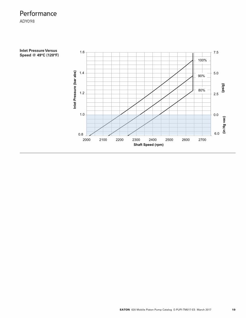
Inlet Pressure Versus Speed @ 49ºC (120ºF)
-2.5
0.0
2.5
5.0
7.5
-2.5
0.0
2.5
5.0
7.5
2000 2100 2200 2300 2400 2500 2600 2700
(psi
g)
Inle
t Pre
ssur
e (b
ar a
bs)
Shaft Speed (rpm)
1.0
0.8
1.2
1.4
1.6
100%
90%
80%
6.0 (inH
g va
c)
20 EATON 620 Mobile Piston Pump Catalog E-PUPI-TM017-E5 March 2017
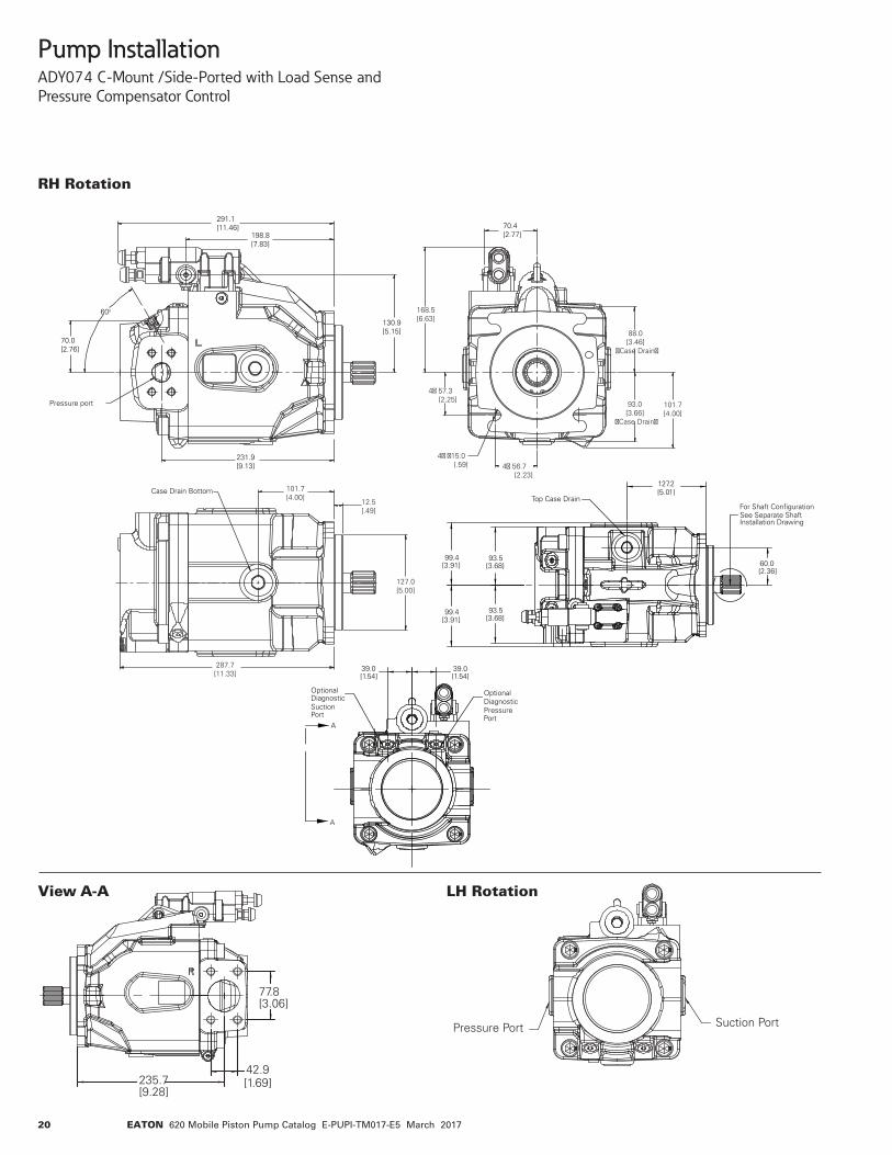
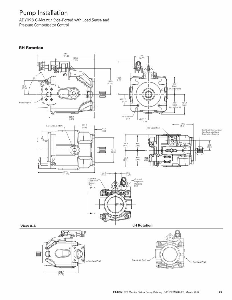
Pump InstallationADY074 C-Mount /Side-Ported with Load Sense and Pressure Compensator Control
View A-A LH Rotation
77.8[3.06]
42.9[1.69]235.7
[9.28]
Suction PortPressure Port
39.0[1.54]
39.0[1.54]
99.4[3.91]
99.4[3.91]
127.2[5.01]
60.0[2.36]
93.5[3.68]
93.5[3.68]
For Shaft Configuration See Separate Shaft Installation Drawing
Top Case Drain
OptionalDiagnosticPressurePort
OptionalDiagnosticSuctionPort
A
A
291.1[11.46]
198.8[7.83]
60o
70.0[2.76]
Pressure port
130.9[5.15]
231.9[9.13]
Case Drain Bottom
70.4[2.77]
168.5[6.63]
4� 57.3 [2.25]
4� �15.0 [.59] 4� 56.7
[2.23]
88.0[3.46]
�Case Drain�
101.7[4.00]
93.0[3.66]
�Case Drain�
101.7[4.00]
12.5[.49]
127.0[5.00]
287.7[11.33]
RH Rotation
21EATON 620 Mobile Piston Pump Catalog E-PUPI-TM017-E5 March 2017
101.74.00[ ]
127.05.00[ ]
4X 56.72.23[ ]
4X 57.32.25[ ]
15.0.59[ ]
99.33.91[ ]
99.63.92[ ]
104.54.11[ ]
168.56.63[ ]
2X 258.110.16[ ]
127.25.01[ ]
105.74.16[ ]
5.25.207[ ]
45.01.77[ ]
47.01.85[ ]
60.02.36[ ]
240.79.48[ ]
(Case Drain)
92.53.64[ ]
(Case Drain)
93.03.66[ ]
PressurePort
For Compensator ConfigurationSee Separate CompensatorInstallation Drawing
OptionalCase Drain
Optional diagnostic
pressure port
Suction Port
A
A
For shaft configurationsee separate shaftinstallation drawing
Top Case Drain
Bottom Case Drain
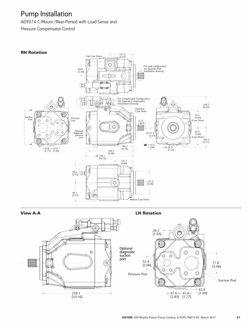
Pump InstallationADY074 C-Mount /Rear-Ported with Load Sense andPressure Compensator Control
View A-A LH Rotation
RH Rotation
258.110.16[ ]
52.42.06[ ]
26.21.03[ ]
42.91.69[ ]
77.83.06[ ]
47.01.85[ ]
45.01.77[ ]
View A – A LH Rotation
74- RP LH
Optionaldiagnosticsuctionport
Pressure Port
Suction Port
22 EATON 620 Mobile Piston Pump Catalog E-PUPI-TM017-E5 March 2017
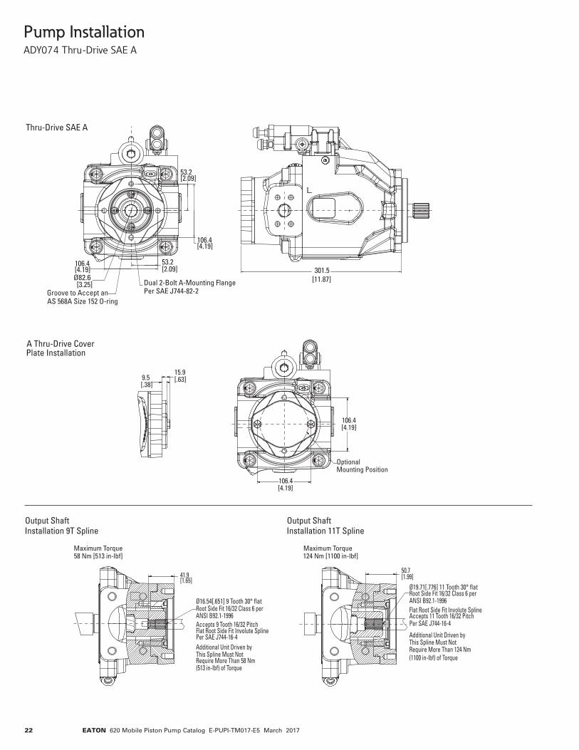
301.5[11.87]
106.4[4.19]
106.4[4.19]
53.2[2.09]
53.2[2.09]
Ø82.6[3.25]
Groove to Accept anAS 568A Size 152 O-ring
Dual 2-Bolt A-Mounting FlangePer SAE J744-82-2
Thru-Drive SAE A
106.4[4.19]
9.5[.38]
15.9[.63]
106.4[4.19]
OptionalMounting Position
A Thru-Drive CoverPlate Installation
41.9[1.65]
50.7[1.99]
Ø16.54[.651] 9 Tooth 30° flatRoot Side Fit 16/32 Class 6 perANSI B92.1-1996Accepts 9 Tooth 16/32 PitchFlat Root Side Fit Involute SplinePer SAE J744-16-4Additional Unit Driven byThis Spline Must NotRequire More Than 58 Nm(513 in-lbf) of Torque
Output Shaft Installation 9T Spline
Output Shaft Installation 11T Spline
Maximum Torque 58 Nm [513 in-lbf]
Maximum Torque 124 Nm [1100 in-lbf]
Ø19.71[.776] 11 Tooth 30° flatRoot Side Fit 16/32 Class 6 perANSI B92.1-1996
Accepts 11 Tooth 16/32 PitchFlat Root Side Fit Involute Spline
Per SAE J744-16-4
Additional Unit Driven byThis Spline Must NotRequire More Than 124 Nm(1100 in-lbf) of Torque
Pump InstallationADY074 Thru-Drive SAE A
23EATON 620 Mobile Piston Pump Catalog E-PUPI-TM017-E5 March 2017
146.0[5.75]
89.8[3.54]
89.8[3.54]
Ø101.7[4.00]
118.0[4.65]
175.2[6.90]
Thru-Drive SAE B
6X .500-13 UNC-2B
Groove to Accept anAS 568A Size 1525O-ring
For Output ShaftConfigurationSee Separate ShaftInstallation Drawing
"X"
Pump InstallationADY074 Thru-Drive SAE B
9.7[0.38]
18.0[0.71]
B-Thru-Drive CoverPlate Installation
41.7[1.64]
Output Shaft Installation 13T Spline
Maximum Torque 209 Nm [1850 in-lbf]
Ø22.88[.901] 13 Tooth 30° FlatRoot Side Fit 16/32 Class 6 perANSI B92.1a-1996
Accepts 13 Tooth 16/32 PitchFlat Root Side Fit Involute SplinePer SAE J744-22-4
This Spline Must NotRequire More Than 209 Nm(1850 in-lbf) of Torque
Additional Unit Driven by
46.0[1.81]
Ø25.68[1.0110] 15 Tooth 30° FlatRoot Side Fit 16/32 Class 6 PerASA B5-15-1960 Accepts 15 Tooth 16/32 Pitch Flat Root Side Fit Involute Spline Per SAE J744-25-4 Additional Unit Driven byThis Spline Must NotRequire More Than 338 Nm(2987 in-lbf) of Torque
Output Shaft Installation 15T SplineMaximum Torque 338 Nm [2987 in-lbf]
Output Shaft Dim “X”13 T spline 301.5 [11.87]15 T spline 317.4 [12.50]
24 EATON 620 Mobile Piston Pump Catalog E-PUPI-TM017-E5 March 2017
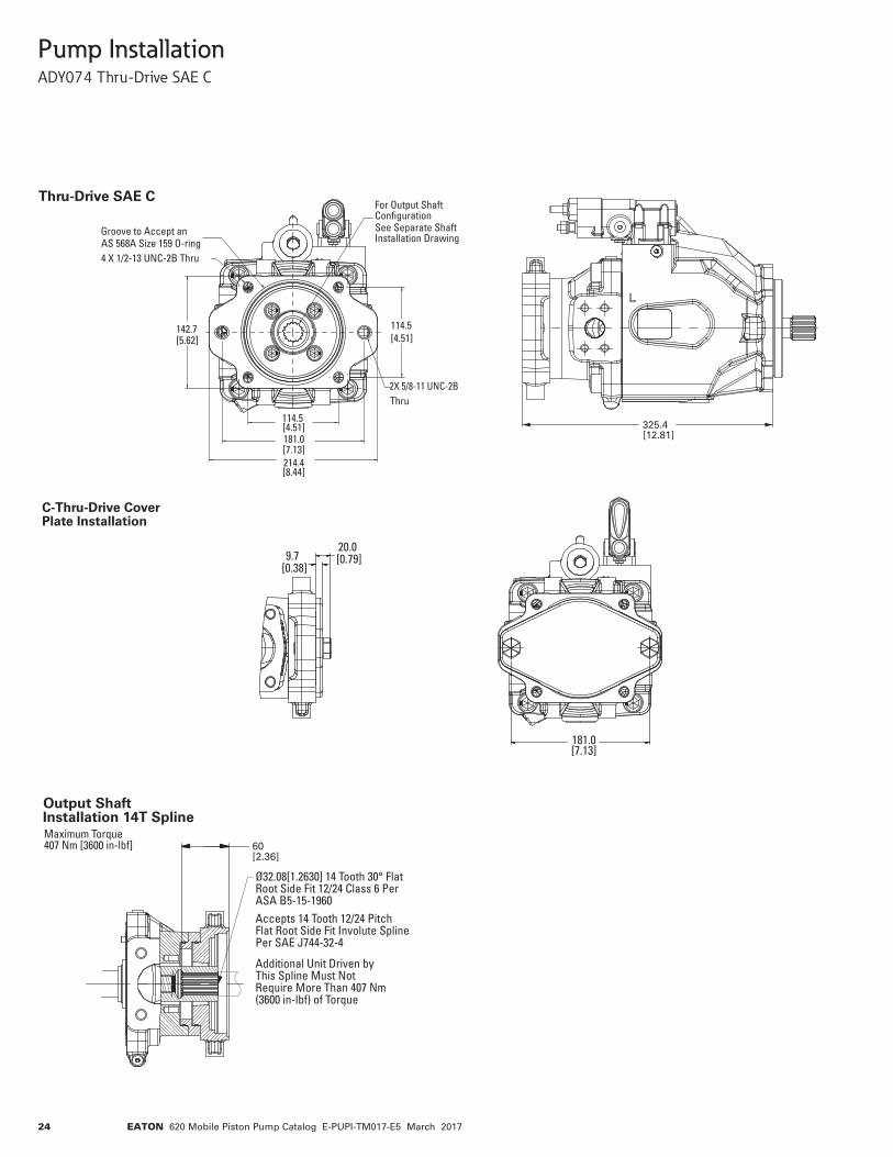
181.0[7.13]
114.5[4.51]
114.5[4.51]
142.7[5.62]
214.4[8.44]
2X 5/8-11 UNC-2BThru
Groove to Accept anAS 568A Size 159 O-ring4 X 1/2-13 UNC-2B Thru
For Output ShaftConfigurationSee Separate ShaftInstallation Drawing
Thru-Drive SAE C
Output Shaft Installation 14T SplineMaximum Torque 407 Nm [3600 in-lbf]
9.7[0.38]
20.0[0.79]
181.0[7.13]
C-Thru-Drive CoverPlate Installation
60[2.36]
Ø32.08[1.2630] 14 Tooth 30° FlatRoot Side Fit 12/24 Class 6 PerASA B5-15-1960
Accepts 14 Tooth 12/24 Pitch Flat Root Side Fit Involute Spline Per SAE J744-32-4
Additional Unit Driven byThis Spline Must NotRequire More Than 407 Nm(3600 in-lbf) of Torque
325.4[12.81]
181.0[7.13]
114.5[4.51]
114.5[4.51]
142.7[5.62]
214.4[8.44]
2X 5/8-11 UNC-2BThru
Groove to Accept anAS 568A Size 159 O-ring4 X 1/2-13 UNC-2B Thru
For Output ShaftConfigurationSee Separate ShaftInstallation Drawing
Thru-Drive SAE C
Output Shaft Installation 14T SplineMaximum Torque 407 Nm [3600 in-lbf]
9.7[0.38]
20.0[0.79]
181.0[7.13]
C-Thru-Drive CoverPlate Installation
60[2.36]
Ø32.08[1.2630] 14 Tooth 30° FlatRoot Side Fit 12/24 Class 6 PerASA B5-15-1960
Accepts 14 Tooth 12/24 Pitch Flat Root Side Fit Involute Spline Per SAE J744-32-4
Additional Unit Driven byThis Spline Must NotRequire More Than 407 Nm(3600 in-lbf) of Torque
325.4[12.81]
Pump InstallationADY074 Thru-Drive SAE C
25EATON 620 Mobile Piston Pump Catalog E-PUPI-TM017-E5 March 2017
Pump InstallationADY098 C-Mount / Side-Ported with Load Sense and Pressure Compensator Control
A
A
4X .375-16 UNC-2B(M10 X 1.5-6HOptional) 14.5 [.57]
OptionalDiagnostic
Port
OptionalDiagnosticPort
For Shaft Con�gurationSee Separate ShaftInsatllation Drawing
288.0[11.34]
101.7[4.00]
12.5[.49]
Ø127.0[5.00]
127.2[5.01]
113.5[4.47]
114.5[4.51]
4X Ø15.0[.59]
88.0[3.46]
(Case Drain)
50.0[1.97]
254.5[10.02]
60.0[2.36]
247.6[9.75]
39.0[1.54]
60°
93.5[3.68]
93.5[3.68]
99.4[3.91]
99.4[3.91]
51.6[2.03]
70.0[2.76]
93.0[3.66]
(Case Drain)
101.7[4.00]
147.0[5.79]
50.0[1.97]
241.7[9.52]
Pressure Port
Top Case Drain
Bottom Case Drain
RH Rotation
(Diagnostic Port)
(Diagnostic Port)
View A-A
Suction Port Suction PortPressure Port
LH Rotation
C-Mount 4 Bolt / Side-Ported
39.0[1.54]
39.0[1.54]
99.4[3.91]
99.4[3.91]
127.2[5.01]
60.0[2.36]
93.5[3.68]
93.5[3.68]
For Shaft Configuration See Separate Shaft Installation Drawing
Top Case Drain
OptionalDiagnosticPressurePort
OptionalDiagnosticSuctionPort
A
A
291.1[11.46]
198.8[7.83]
60o
70.0[2.76]
Pressure port
130.9[5.15]
231.9[9.13]
Case Drain Bottom
70.4[2.77]
168.5[6.63]
4� 57.3 [2.25]
4� �15.0 [.59] 4� 56.7
[2.23]
88.0[3.46]
�Case Drain�
101.7[4.00]
93.0[3.66]
�Case Drain�
101.7[4.00]
12.5[.49]
127.0[5.00]
287.7[11.33]
RH Rotation
26 EATON 620 Mobile Piston Pump Catalog E-PUPI-TM017-E5 March 2017
Pump InstallationADY098 C-Mount /Rear-Ported with Load Sense andPressure Compensator Control
52.42.06[ ]
89.03.50[ ]
26.21.03[ ]
50.82.00[ ]98.0
3.86[ ]259.210.20[ ]
98CC LH
View A – A LH Rotation
Pressure Port
Suction Port
259.210.20[ ]
118.74.67[ ]
127.005.000[ ]
144.25.68[ ]
4X 56.72.23[ ]
4X 57.32.25[ ]
15.0.59[ ]
(Case Drain)
88.03.46[ ]
(Case Drain)
93.03.66[ ]
99.33.91[ ]
99.43.91[ ]
90.03.54[ ]
90.03.54[ ]
238.29.38[ ]
230.29.06[ ]
168.56.63[ ]
53.02.09[ ]
45.01.77[ ]
89.73.53[ ]
89.73.53[ ]
60.02.36[ ]
101.74.00[ ]
238.29.38[ ]
2X 17.5.69[ ]
Pressure Port
OptionalDiagnostic Port
For Compensator ConfigurationSee Separate CompensatorInstallation Drawing
OptionalDiagnostic
Port
Suction Port
A
A
For Shaft ConfigurationSee Separate ShaftInstallation Drawing
Top Case Drain
Bottom Case Drain
OptionalDiagnostic Port
RH Rotation

27EATON 620 Mobile Piston Pump Catalog E-PUPI-TM017-E5 March 2017
318.1[12.52]
106.4[4.19]
106.4[4.19]
53.2[2.09]
53.2[2.09]
Ø82.6[3.25]
Groove to Accept anAS 568A Size 152 O-ring
Dual 2-Bolt A-Mounting FlangePer SAE J744-82-2
Thru-Drive SAE A
106.4[4.19]
9.5[.38]
15.9[.63]
106.4[4.19]
OptionalMounting Position
A Thru-Drive CoverPlate Installation
41.9[1.65]
50.7[1.99]
Ø16.54[.651] 9 Tooth 30° flatRoot Side Fit 16/32 Class 6 perANSI B92.1-1996Accepts 9 Tooth 16/32 PitchFlat Root Side Fit Involute SplinePer SAE J744-16-4
Additional Unit Driven byThis Spline Must NotRequire More Than 58 Nm(513 in-lbf) of Torque
Output Shaft Installation 9T Spline
Output Shaft Installation 11T Spline
Maximum Torque 58 Nm [513 in-lbf]
Maximum Torque 124 Nm [1100 in-lbf]
Ø19.71[.776] 11 Tooth 30° flatRoot Side Fit 16/32 Class 6 perANSI B92.1-1996
Accepts 11 Tooth 16/32 PitchFlat Root Side Fit Involute Spline
Per SAE J744-16-4
Additional Unit Driven byThis Spline Must NotRequire More Than 124 Nm(1100 in-lbf) of Torque
Pump InstallationADY098 Thru-Drive SAE A
28 EATON 620 Mobile Piston Pump Catalog E-PUPI-TM017-E5 March 2017
318.1[12.52]146.0
[5.75]
89.8[3.54]
89.8[3.54]
Ø101.7[4.00]
118.0[4.65]
175.2[6.90]
Thru-Drive SAE B
6X .500-13 UNC-2B
Groove to Accept anAS 568A Size 1525O-ring
For Output ShaftConfigurationSee Separate ShaftInstallation Drawing
Pump InstallationADY098 Thru-Drive SAE B
9.7[0.38]
18.0[0.71]
B-Thru-Drive CoverPlate Installation
41.7[1.64]
Output Shaft Installation 13T Spline
Maximum Torque 209 Nm [1850 in-lbf]
Ø22.88[.901] 13 Tooth 30° FlatRoot Side Fit 16/32 Class 6 perANSI B92.1a-1996
Accepts 13 Tooth 16/32 PitchFlat Root Side Fit Involute SplinePer SAE J744-22-4
This Spline Must NotRequire More Than 209 Nm(1850 in-lbf) of Torque
Additional Unit Driven by
58.3[2.30]
Output Shaft Installation 15T SplineMaximum Torque 338 Nm [2987 in-lbf]
Ø25.68[1.0110] 15 Tooth 30° FlatRoot Side Fit 16/32 Class 6 perASA B5-15-1960
Accepts 15 Tooth 16/32 PitchFlat Root Side Fit Involute SplinePer SAE J744-25-4
This Spline Must NotRequire More Than 338 Nm(2987 in-lbf) of Torque
Additional Unit Driven by

29EATON 620 Mobile Piston Pump Catalog E-PUPI-TM017-E5 March 2017
326.1[12.84]181.0
[7.13]
114.5[4.51]
114.5[4.51]
142.7[5.62]
214.4[8.44]
2X 5/8-11 UNC-2BThru
Groove to Accept anAS 568A Size 159 O-ring4 X 1/2-13 UNC-2B Thru
For Output ShaftConfigurationSee Separate ShaftInstallation Drawing
Thru-Drive SAE C
60.3[2.37]
Output Shaft Installation 17T SplineMaximum Torque 553 Nm [4890 in-lbf]
Ø38.94[1.533] 17 Tooth 30° FlatRoot Side Fit 12/24 Class 6 perANSI B92.1a-1976Accepts 17 Tooth 16/32 PitchFlat Root Side Fit Involute SplinePer SAE J744-38-4
This Spline Must NotRequire More Than 553 Nm(4890 in-lbf) of Torque
Additional Unit Driven by
64.0[2.52]
Output Shaft Installation 14T SplineMaximum Torque 553 Nm [4890 in-lbf]
Ø32.08[1.2630] 14 Tooth 30° FlatRoot Side Fit 12/24 Class 6 PerASA B5.15-1960Accepts 14 Tooth 12/24 PitchFlat Root Side Fit Involute SplinePer SAE J744-32-4
This Spline Must NotRequire More Than 553 Nm(4890 in-lbf) of Torque
Additional Unit Driven by
9.7[0.38]
20.0[0.79]
181.0[7.13]
C-Thru-Drive CoverPlate Installation
Pump InstallationADY098 Thru-Drive SAE C
30 EATON 620 Mobile Piston Pump Catalog E-PUPI-TM017-E5 March 2017
Control InstallationPressure Compensator
71.9[2.83]
140.3[5.52]
119.8[4.72]
126.1[4.96]
158.1[6.22]
31EATON 620 Mobile Piston Pump Catalog E-PUPI-TM017-E5 March 2017
Control InstallationLoad Sense and Pressure Compensator
196.87.75[ ]
122.54.82[ ]
Max. Length Load Sense285.311.23[ ]
Max. Length Pressure Compensator294.211.58[ ]
130.95.15[ ]
168.56.63[ ]
70.42.77[ ]
154.36.07[ ]
213.8 [8.42]
With Double Shaft Seal
Load Sense Port

32 EATON 620 Mobile Piston Pump Catalog E-PUPI-TM017-E5 March 2017
Control InstallationEH Inverse Proportional Pressure Control (IPPC)
208.1[8.19]
124.2[4.89]
188.4[7.42]
129.8[5.11]
81.8[3.22]
DEUTSCH CONNECTOR OPTIONAMP CONNECTOR OPTION
AMP CONNECTOR DEUTSCH CONNECTOR
33EATON 620 Mobile Piston Pump Catalog E-PUPI-TM017-E5 March 2017
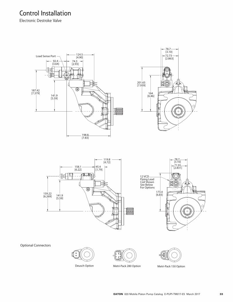
Control InstallationElectronic Destroke Valve
187.42[7.379]
198.8[7.83]
72.73[2.863]
201.65[7.939]
92.4[3.64]
124.5[4.90]
141.9[5.59]
74.3[2.93]
78.7[3.10]
164[6.46]
159.22[6.269]
71.91[2.831]158.1
[6.22]45.4[1.79]
141.9[5.59]
78.7[3.10]
173.4[6.83]
119.8[4.72]
Load Sense Port
12 VCDFlying LeadCoil ShownSee BelowFor Options
Metri-Pack 280 OptionDeusch Option Metri-Pack 150 Option
Optional Connectors
34 EATON 620 Mobile Piston Pump Catalog E-PUPI-TM017-E5 March 2017
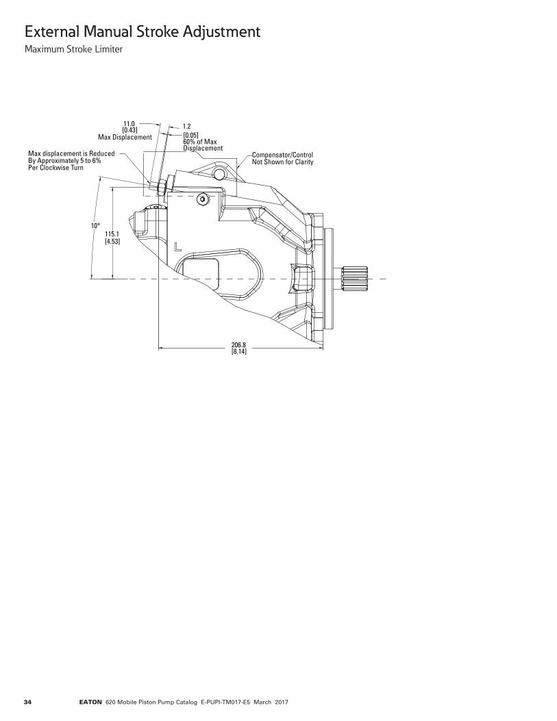
External Manual Stroke AdjustmentMaximum Stroke Limiter
10°
1.2[0.05]60% of MaxDisplacement
11.0[0.43]
Max Displacement
115.1[4.53]
206.8[8.14]
Compensator/ControlNot Shown for Clarity
Max displacement is ReducedBy Approximately 5 to 6%Per Clockwise Turn
35EATON 620 Mobile Piston Pump Catalog E-PUPI-TM017-E5 March 2017
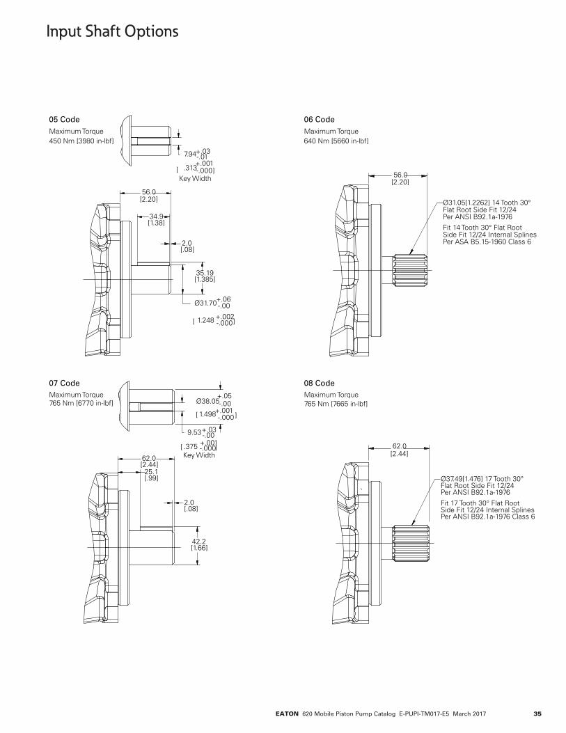
Input Shaft Options
56.0[2.20]
7.94+.03-.01
.313+.001-.000
Key Width[ ]
35.19[1.385]
2.0[.08]
34.9[1.38]
Ø31.70+.06-.00
[ 1.248 +.002-.000]
05 CodeMaximum Torque450 Nm [3980 in-lbf]
9.53+.03-.00
.375 +.001-.000
Key Width[ ]
62.0[2.44]
42.2[1.66]
25.1[.99]
2.0[.08]
Ø38.05+.05-.00
[ 1.498+.001-.000]
07 CodeMaximum Torque765 Nm [6770 in-lbf]
62.0[2.44]
08 Code
Ø37.49[1.476] 17 Tooth 30°Flat Root Side Fit 12/24 Per ANSI B92.1a-1976
Fit 17 Tooth 30° Flat RootSide Fit 12/24 Internal SplinesPer ANSI B92.1a-1976 Class 6
Maximum Torque765 Nm [7665 in-lbf]
56.0[2.20]
Ø31.05[1.2262] 14 Tooth 30°Flat Root Side Fit 12/24Per ANSI B92.1a-1976Fit 14 Tooth 30° Flat RootSide Fit 12/24 Internal SplinesPer ASA B5.15-1960 Class 6
06 CodeMaximum Torque640 Nm [5660 in-lbf]
36 EATON 620 Mobile Piston Pump Catalog E-PUPI-TM017-E5 March 2017
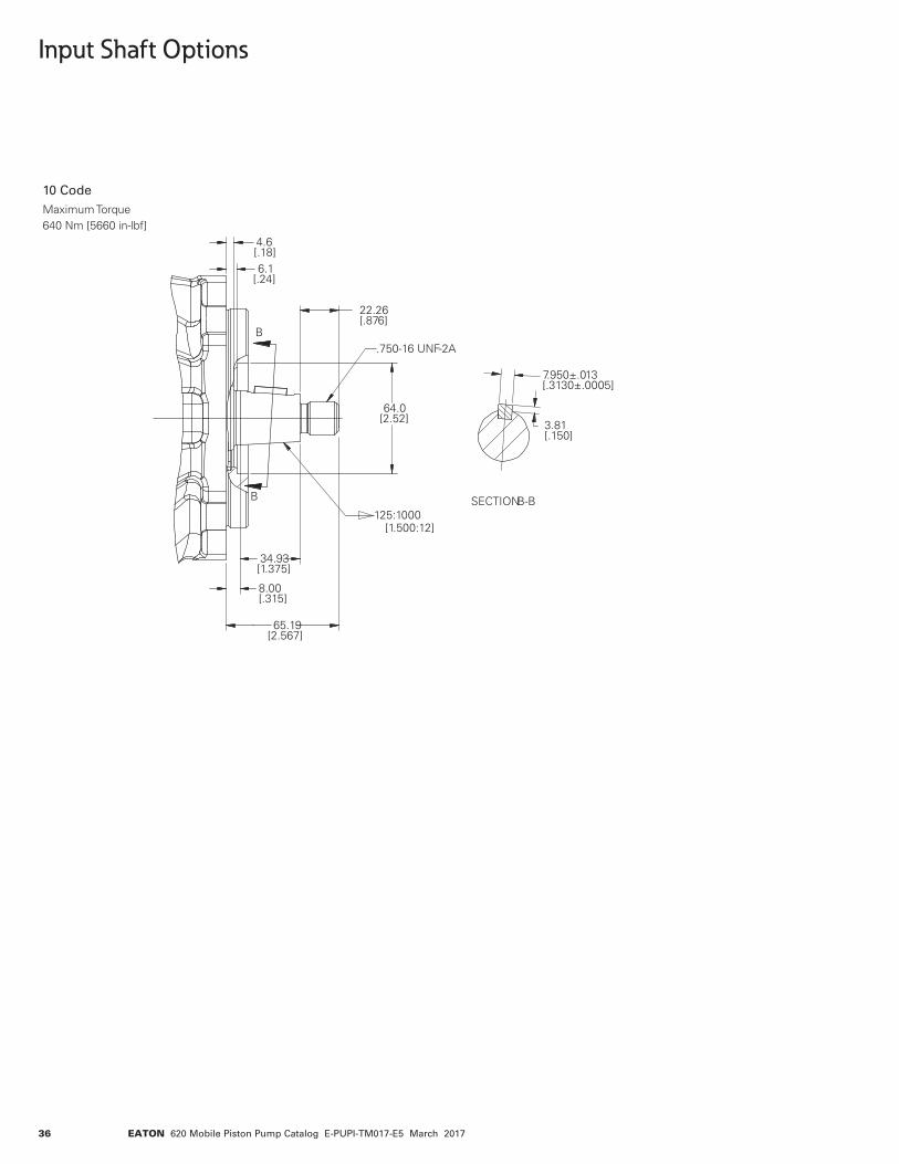
Input Shaft Options
B
B
65.19[2.567]
22.26[.876]
64.0[2.52] 3.81
[.150]
7.950±.013[.3130±.0005]
34.93[1.375]
8.00[.315]
4.6[.18]6.1
[.24]
.750-16 UNF-2A
125:1000 [1.500:12]
SECTION B-B
10 CodeMaximum Torque640 Nm [5660 in-lbf]
37EATON 620 Mobile Piston Pump Catalog E-PUPI-TM017-E5 March 2017
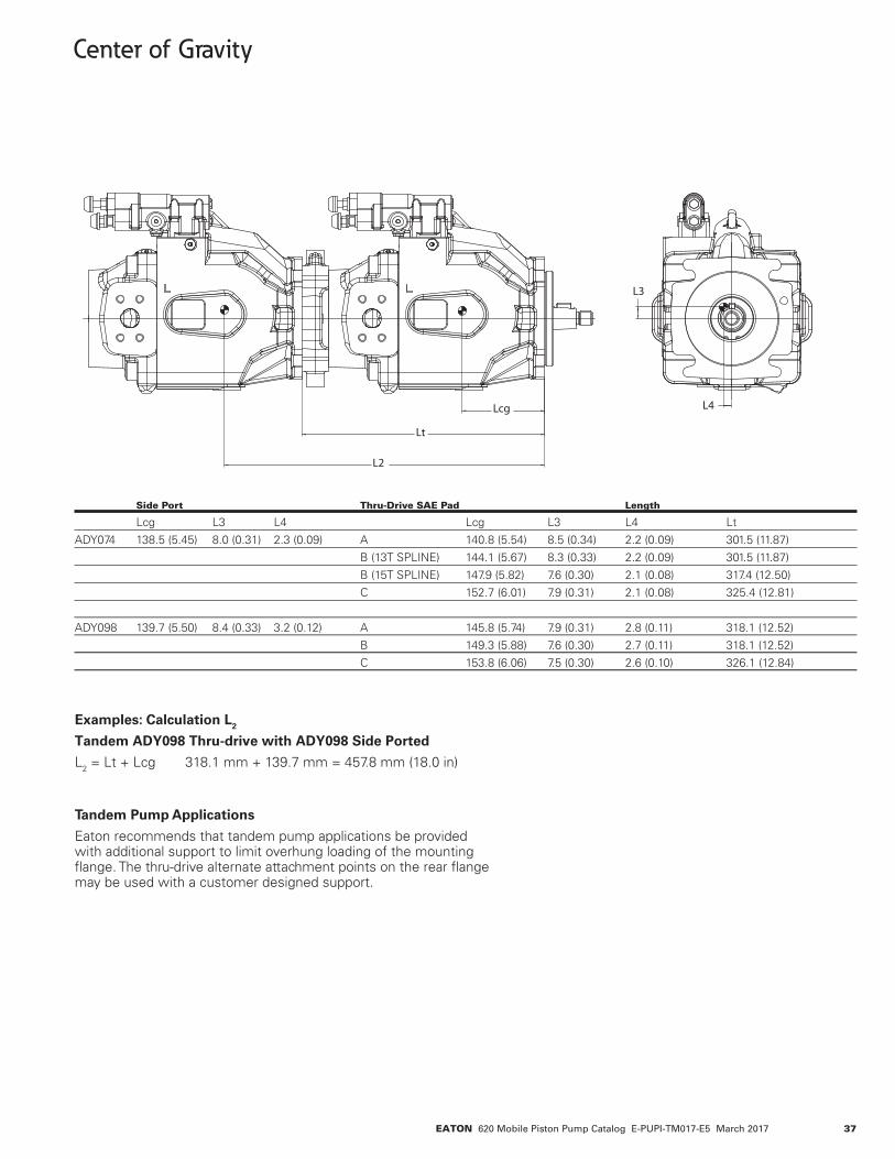
Center of Gravity
Side Port Thru-Drive SAE Pad Length
Lcg L3 L4 Lcg L3 L4 LtADY074 138.5 (5.45) 8.0 (0.31) 2.3 (0.09) A 140.8 (5.54) 8.5 (0.34) 2.2 (0.09) 301.5 (11.87) B (13T SPLINE) 144.1 (5.67) 8.3 (0.33) 2.2 (0.09) 301.5 (11.87) B (15T SPLINE) 147.9 (5.82) 7.6 (0.30) 2.1 (0.08) 317.4 (12.50) C 152.7 (6.01) 7.9 (0.31) 2.1 (0.08) 325.4 (12.81)
ADY098 139.7 (5.50) 8.4 (0.33) 3.2 (0.12) A 145.8 (5.74) 7.9 (0.31) 2.8 (0.11) 318.1 (12.52) B 149.3 (5.88) 7.6 (0.30) 2.7 (0.11) 318.1 (12.52) C 153.8 (6.06) 7.5 (0.30) 2.6 (0.10) 326.1 (12.84)
Examples: Calculation L2
Tandem ADY098 Thru-drive with ADY098 Side Ported
L2 = Lt + Lcg 318.1 mm + 139.7 mm = 457.8 mm (18.0 in)
Tandem Pump Applications
Eaton recommends that tandem pump applications be provided with additional support to limit overhung loading of the mounting flange. The thru-drive alternate attachment points on the rear flange may be used with a customer designed support.
Lcg
Lt
L2
L4
L3
38 EATON 620 Mobile Piston Pump Catalog E-PUPI-TM017-E5 March 2017
Fluid Cleanliness
The 620 Series pumps are rated in anti-wear petroleum fluids with a contamination level of 21/18/13 per ISO 4406. Operation in fluids with levels more contaminated than this is not recommend-ed. Fluids other than petro-leum, severe service cycles, or temperature extremes are cause for adjustment of these codes. Please contact your Eaton Representative for specific duty cycle recom-mendation.
Eaton 620 Series pumps, as with any variable displace-ment piston pumps, will op-erate with apparent satisfac-tion in fluids up to the rating specified here. Experience has shown however, that pump and hydraulic system life is not optimized with high fluid contamination levels (high ISO cleanliness codes).
Proper fluid condition is essential for long and satisfac tory life of hydraulic components and systems. Hydraulic fluid must have the
correct balance of cleanli-ness, materials, and additives for protection against wear of components, elevated viscosity and inclusion of air.
Essential information on the correct methods for treating hydraulic fluid is included in Eaton publication 561 – “Eaton Guide to Systemic Contamination Control” – available from your local Eaton distributor. In this pub-lication, filtration and cleanli-ness levels for extending the life of axial piston pumps and
other system components are listed. Included is an excellent discussion of the selection of products needed to control fluid condition.
Installation and Start-up
Warning: Care should be taken that mechanical and hydraulic resonances are avoided in the application of the pump. Such resonances can seriously compromise the life and/or safe operation of the pump.
Drive Data
Mounting attitude should be horizontal using the appro-priate case drain ports to ensure that the case remains full of fluid at all times. Consult your local Eaton Representative if a different arrangement is required.
In those cases where geo-metric tolerances of mount-ing are critical, or where specific tolerance ranges are required and not specified, consult Eaton Engineering for specific limits.
Direction of shaft rotation, viewed from the prime mov-er end, must be as indicated in the model designation on the pump – either right hand (clockwise) or left hand (counterclockwise).
Direct coaxial drive through a flexible coupling is recom-mended. If drives imposing radial shaft loads are con-sidered, please consult your Eaton Representative.
Start-up Procedure
Make sure the reservoir and circuit are clean and free of dirt/debris prior to filling with hydraulic fluid.
Fill the reservoir with filtered oil and fill to a level sufficient enough to prevent vortexing at the suction connection to pump inlet. It is good practice to clean the system by flush-ing and filtering, using an external slave pump.
Caution: Before the pump is started, fill the case through the uppermost drain port with hydraulic fluid of the type to be used. The case drain line must be connected directly to the reservoir and must terminate below the oil level.
Once the pump is started, it should prime within a few seconds. If the pump does not prime, check to make sure that there are no restric-tions between the reservoir and the inlet to the pump, and that the pump is being rotated in the proper direc-tion, and that there are no air leaks in the inlet line and con-nections. Also check to make sure that trapped air can escape at the pump outlet.
After the pump is primed, tighten the loose outlet con-nections, then operate for five to ten minutes (unload-ed) to remove all trapped air from the circuit.
If the reservoir has a sight gage, make sure the fluid is clear – not milky.

39EATON 620 Mobile Piston Pump Catalog E-PUPI-TM017-E5 March 2017
Notes
© 2017 EatonAll Rights Reserved Printed in USADocument No. E-PUPI-TM017-E5 Supersedes E-PUPI-TM017-E4March 2017
Eaton Hydraulics Group USA14615 Lone Oak RoadEden Prairie, MN 55344USATel: 952-937-9800Fax: 952-294-7722www.eaton.com/hydraulics
EatonHydraulics Group EuropeRoute de la Longeraie 71110 MorgesSwitzerlandTel: +41 (0) 21 811 4600Fax: +41 (0) 21 811 4601
EatonHydraulics Group Asia PacificEaton BuildingNo.7 Lane 280 Linhong RoadChangning District, Shanghai200335 ChinaTel: (+86 21) 5200 0099Fax: (+86 21) 2230 7240