650 853 professional - gebrueder-prinz.de · manual de uso y mantenimiento codigo 90103091 edición...
TRANSCRIPT

SERIE
MANUALE D’USO E MANUTENZIONE Codic
OWNER’S MANUAL Code
MANUEL D’ENTRETIEN Code
MANUAL DE USO Y MANTENIMIENTO Codig
WARTUNGSANLEITUNG Kode
BCS S.p.A. - V.le Mazzini, 161 - 2008
• MOTOFALCIATRICI
• MOTORMOWERS
• MOTOFAUCHEUSES
• MOTOSEGADORAS
• MOTORMÄHER
•
•
•
•
•
0 650Mod. 852 PROFESSIONAL 853 PROFESSIONAL
06
MOTOCOLTIVATORI
TWO-WHEEL TRACTORS 740
MOTOCULTEURS Mod. 746
MOTOCULTORES 948
60
70
e 90103091
90103091
90103091
o 90103091
zahl 9010309
1 ABBIATEG
EINACHSER
0
Edizione 02 .06
Edition 02 .06
Edition 02 .06
Edición 02 .06
1 Ausgabe 02 .06
RASSO - MI - Italia
2
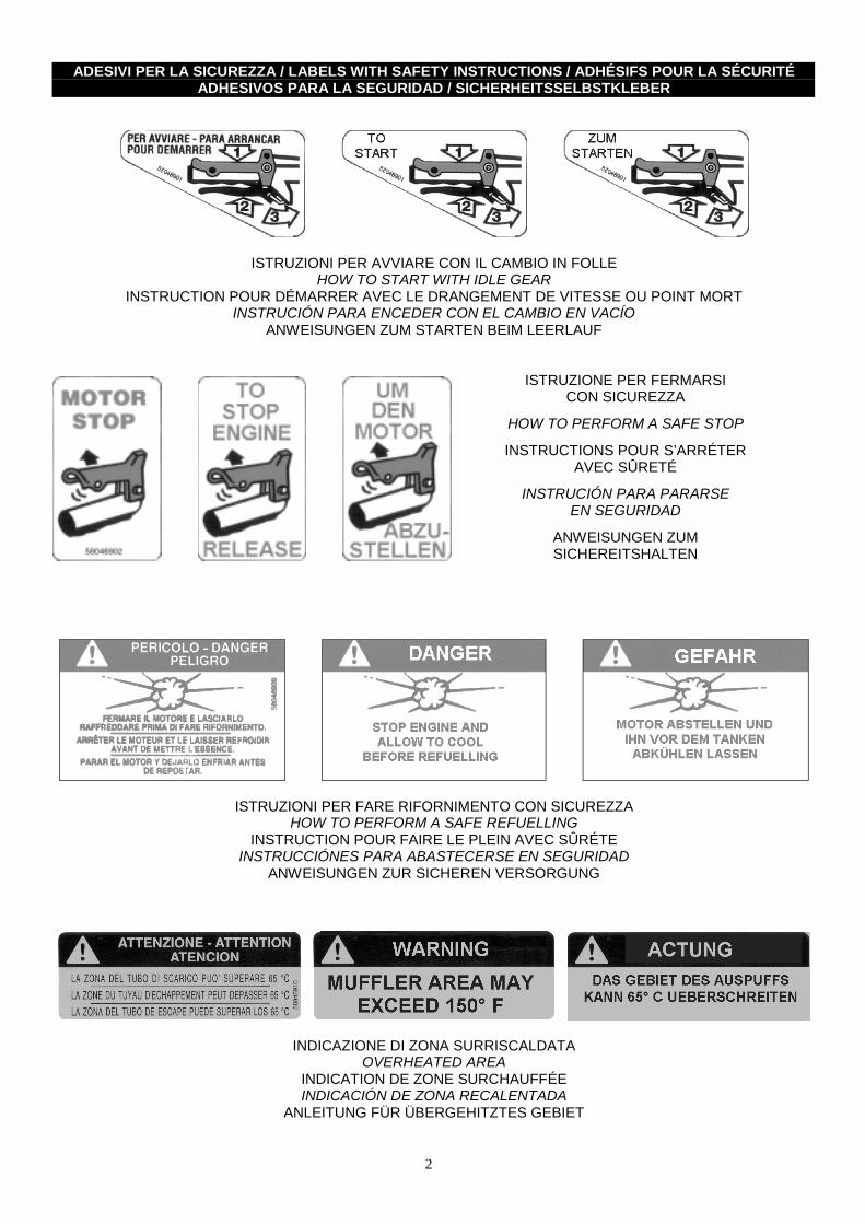
ADESIVI PER LA SICUREZZA / LABELS WITH SAFETY INSTRUCTIONS / ADHÉSIFS POUR LA SÉCURITÉADHESIVOS PARA LA SEGURIDAD / SICHERHEITSSELBSTKLEBER
ISTRUZIONI PER AVVIARE CON IL CAMBIO IN FOLLEHOW TO START WITH IDLE GEAR
INSTRUCTION POUR DÉMARRER AVEC LE DRANGEMENT DE VITESSE OU POINT MORTINSTRUCIÓN PARA ENCEDER CON EL CAMBIO EN VACÍO
ANWEISUNGEN ZUM STARTEN BEIM LEERLAUF
ISTRUZIONI PER FARE RIFORNIMENTO CON SICUREZZAHOW TO PERFORM A SAFE REFUELLING
INSTRUCTION POUR FAIRE LE PLEIN AVEC SÛRÉTEINSTRUCCIÓNES PARA ABASTECERSE EN SEGURIDAD
ANWEISUNGEN ZUR SICHEREN VERSORGUNG
INDICAZIONE DI ZONA SURRISCALDATAOVERHEATED AREA
INDICATION DE ZONE SURCHAUFFÉEINDICACIÓN DE ZONA RECALENTADA
ANLEITUNG FÜR ÜBERGEHITZTES GEBIET
ISTRUZIONE PER FERMARSICON SICUREZZA
HOW TO PERFORM A SAFE STOP
INSTRUCTIONS POUR S’ARRÉTERAVEC SÛRETÉ
INSTRUCIÓN PARA PARARSEEN SEGURIDAD
ANWEISUNGEN ZUMSICHEREITSHALTEN

3
Le macchine comprese in questo manualesono costruite in accordo
con la direttiva macchine CEE 89/392e successive modificazioni.
La società BCS si complimenta con Voi per la scelta di un no-stro prodotto garantendoVi il massimo dell'assistenza e dellacollaborazione che da sempre contraddistinguono il nostromarchio.Questa pubblicazione Vi aiuterà a conoscere meglio la Vostramacchina. Se verrà usata seguendo queste istruzioni Vi dure-rà molti anni e Vi sarà di prezioso aiuto per svolgere i Vostrilavori agricoli. Vi raccomandiamo pertanto di leggere attenta-mente queste pagine e di seguire sempre i consigli.
The machines described in this manual havebeen built according to the EEC rule 89/392
and further modifications.
BCS congratulates with You for Your purchasing a machinefrom our range. We will grant the assistance and cooperationwhich have always been a feature of our products.If used in accordance with the instruction contained in yourowner’s manual, your machine will last many years and willprove to be of an invaluable assistance to you. We thereforerecommend that You read the manual carefully and follow theadvice given.
Les machines qui se trouvent dansce manuel, sont construites suivant la norme
des machines CEE 89/392 etses modifications successives.
La société BCS Vous félicite pour le choix d’un de nos produiten Vous assurant le maximum de notre assistance et collabo-ration qui ont toujours distingué notre marque.Cette publication Vous aidera à mieux connaître Votre machi-ne. Si vous l'utilisez conformément aux instructions contenuesdans ce manuel, elle durera de nombreuses années et sera pourVous une aide précieuse pour vos travaux agricoles. Nous Vous recommandons, par conséquent, de lire ces pa-ges avec attention et de suivre scrupuleusement les conseils.
Las máquinas incluidas en este manual hansido producidas según la directiva CEE 89/392por las máquinas, y variacciones siguientes.
La sociedad BCS se alegra con Usted por haber escogidonuestro producto. BCS puede asegurar la maxima asistenciay collaboración que siempre han caracterizado nuestramarca.Este libro le ayudará a conocer mejor su máquina. Si la usa si-guiendo estas instrucciones le durerà muchos años y la será degran ayuda para desarrollar sus trabajos agrícolas.Le recomendamos pues, leer atentamente estas páginas y se-guir siempre los consejos que en ellas encontrarà.
Die in diesem Handbuch beschriebenenMaschinen, werden nach EEG 89/392Maschinennormen und ihren weiteren
Änderungen produziert.
BCS erfreut sich um Ihre Wahl. Unsere Firma wird zweifellosIhnen seine beste Wartung und Zusammenarbeit bieten, dieseit immer BCS-Produkte kennzeichen. Wenn Sie in diesem Handbuch erteilten Anleitungen beherzigen,wird Ihre Maschine über lange Zeit eine wertvolle Hilfe sein. Bitte lesen Sie daher die vorliegende Bedienungsanleitungaufmerksam durch und befolgen Sie die erteilten Ratschläge.

4
INDICEIDENTIFICAZIONE E MARCATURASIMBOLOGIAAVVERTENZEINFORMAZIONI PER L'OPERATOREMOTOCOLTIVATORIMOTOFALCIATRICIMONTAGGIO DELLA MACCHINANORME DI SICUREZZADESCRIZIONE DEI COMANDIAPPLICAZIONE ATTREZZIPRESA DI POTENZACONTROLLI DA ESEGUIRE PRIMA DI AVVIAREAVVIAMENTO DELLA MACCHINA
pag. 6 ” 8 ” 8 ” 10 ” 11 ” 12 ” 13 ” 14 ” 17 ” 19 ” 21 ” 22 ” 23
LUBRIFICAZIONE E MANUTENZIONETABELLA 1 : RUOTETABELLA 2 : MOTORITABELLA 3 : VELOCITA'CARATTERISTICHE TECNICHEATTREZZI APPLICABILIACCESSORIATTREZZI ED ACCESSORI SPECIALIAVVIAMENTO ELETTRICOARATRIASSOLCATORE RETROFRESAASSOLCATORE REGISTRABILECARRELLO DI TRASFERIMENTO
pag. 27 ” 29 ” 30 ” 30 ” 31 ” 33 ” 33 ” 34 ” 35 ” 39 ” 40 ” 42 ” 43
INDEX IDENTIFICATION AND TAGGINGSYMBOLSWARNINGSINFORMATION FOR THE USERTWO-WHEEL TRACTORSMOTOR MOWERSMACHINE ASSEMBLYGENERAL SAFETYCONTROL DESCRIPTIONIMPLEMENT ASSEMBLYP.T.O. CHECKS BEFORE STARTING THE MACHINE TO START THE MACHINE
page 6 ” 8 ” 8 ” 10 ” 11 ” 12 ” 13 ” 14 ” 17 ” 19 ” 21 ” 22 ” 23
LUBRICATION AND MAINTENANCETABLE 1 : WHEELSTABLE 2 : ENGINESTABLE 3 : SPEEDSTECHNICAL FEATURESPOSSIBLE IMPLEMENTSACCESSORIESSPECIAL IMPLEMENTS AND ACCESSORIESELECTRIC STARTERPLOUGHSRIDGER ADAPTABLE BEHIND ROTARY HOEADJUSTABLE RIDGERMOVING SULKY
page 27 ” 29 ” 30 ” 30 ” 31 ” 33 ” 33 ” 34 ” 35 ” 39 ” 40 ” 42 ” 43
CONTENUIDENTIFICATION ET MARQUAGESYMBOLESRECOMMANDATIONSINFORMATIONS POUR L'OPÉRATEURMOTOCULTEURSMOTOFAUCHEUSESMONTAGE DE LA MACHINEREGLES DE SECURITE GENERALEDESCRIPTION DES COMMANDESMONTAGE OUTILSPRISE DE PUISSANCECONTROLES A EFFECTUER AVANT DE DEMARRERDEMARRAGE DE LA MACHINE
page 6 ” 8 ” 8 ” 10 ” 11 ” 12 ” 13 ” 14 ” 17 ” 19 ” 21 ” 22 ” 23
LUBRIFICATION ET ENTRETIENTABLEAU 1 : ROUESTABLEAU 2 : MOTEURSTABLEAU 3 : VITESSESCARACTERISTIQUES TECHNIQUESOUTILS ADAPTABLESACCESSOIRESOUTILS AND ACCESSOIRES SPECIAUXDEMARRAGE ELECTRIQUECHARRUESBUTTOIR MONTE DERRIERE LA FRAISEBUTTOIR A AILES REGLABLESSULKY DE DEPLACEMENT
page 27 ” 29 ” 30 ” 30 ” 31 ” 33 ” 33 ” 34 ” 35 ” 39 ” 40 ” 42 ” 43
INDICEIDENTIFICACIÓN Y MARCASSIMBOLOGÍAADVERTENCIASINFORMACCIONES PARA EL UTILIZADORMOTOCULTORESMOTOSEGADORASMONTAJE DE LA MAQUINANORMAS DE SEGURIDADDESCRIPCION DE LOS MANDOSAPLICACION APEROSTOMA DE FUERZACONTR. A EFECTUAR ANTES DE PONER EN MARCHAARRANQUE DE LA MAQUINA
pag. 6 ” 8 ” 8 ” 10 ” 11 ” 12 ” 13 ” 14 ” 17 ” 19 ” 21 ” 22 ” 23
LUBRICACION Y MANTENIMIENTOTABLA 1 : RUEDASTABLA 2 : MOTORESTABLA 3 : VELOCIDADESCARACTERISTICAS TECNICASAPEROS APLICABLESACCESORIOSAPEROS Y ACCESORIOS ESPECIALESARRANQUE ELECTRICOARADOSSURCADOR RETROFRESASURCADOR REGISTRABLECARRO DE TRANSPORTE
pag. 27 ” 29 ” 30 ” 30 ” 31 ” 33 ” 33 ” 34 ” 35 ” 39 ” 40 ” 42 ” 43
INHALTIDENTIFIZIERUNG UND MARKIERUNGSYMBOLEBEMERKUNGENINFORMATIONEN FÜR DEN OPERATOREINÄCHSERMOTORMÄHERMASCHINEMONTAGESICHERHEITSVORSCHRIFTENBESCHREIBUNG DER BEDIENUNGSORGANEMONTAGE DER ARBEITSGERÄTEZAPFWELLEVOR DEN INBETRIEBNAHME VORZUNEHMENDE KNTR.INBETRIEBNAHME DER MASCHINE
Seite 6 ” 8 ” 8 ” 10 ” 11 ” 12 ” 13 ” 14 ” 17 ” 19 ” 21 ” 22 ” 23
SCHMIERUNG UND WARTUNGTAFEL 1 : RÄDERTAFEL 2 : MOTORENTAFEL 3 : GESCHWINDIGKEITENTECNISCHE EIGENSCHAFTENMÖGLICHE ARBEITSGERÄTEZUBEHÖRSPEZIELLE ARBEITSGERÄTE UND ZUBEHÖRELEKTROSTARTERPFLÜGEFURCHENZIEHER HINTER DER FRÄSEVERSTELLBARER FURCHENZIEHERTRANSPORTSITZWAGEN
Seite 27 ” 29 ” 30 ” 30 ” 31 ” 33 ” 33 ” 34 ” 35 ” 39 ” 40 ” 42 ” 43

5
CARRELLO DI LAVORORIMORCHIO A RUOTE LIBERERUOTE PNEUMATICHERUOTE “SUPER-BITE”RUOTE METALLICHE A GABBIAANELLI DI GEMELLAGGIOGEMELLAGGIO RUOTEDISTANZIALI PER RUOTEZAVORRE PER RUOTEATTACCO CURVORUOTINO SOSTEGNO FRESAPROTEZIONE ANTERIORE PER BARRAPROTEZIONI LATERALI PER BARRA
pag. 43 ” 45 ” 46 ” 47 ” 48 ” 48 ” 49 ” 50 ” 51 ” 53 ” 54 ” 55 ” 55
ATTACCO RAPIDO ATTREZZIPRESA DI FORZA UNIFICATA D=35CATENE DA NEVEPOSSIBILI INCONVENIENTI E LORO RIMEDIPERIODI DI LUNGA INATTIVITA'COME SOSTITUIRE LA FRIZIONE (figura 69)DOTAZIONEGARANZIACERTIFICATI E DICHIARAZIONIPARTICOLARI DI CONSUMOMODALITA' DI VENDITA DEI RICAMBI
pag. 57 ” 59 ” 59 ” 61 ” 64 ” 65 ” 67 ” 67 ” 68 ” 69 ” 70
WORKING SULKYTRAILER WITH FREE WHEELSPNEUMATIC WHEELSWHEELS “SUPER-BITE”STEEL CAGE WHEELSTWINNING RINGSWHEELS TWINNINGWHEEL SPACERSBALLASTS FOR WHEELSCURVED COUPLINGROTARY HOE WHEELCUTTER BAR FRONT PROTECTIONCUTTER BAR SIDE PROTECTIONS
page 43 ” 45 ” 46 ” 47 ” 48 ” 48 ” 49 ” 50 ” 51 ” 53 ” 54 ” 55 ” 55
QUICK HITCH FOR IMPLEMENTSSTANDARD POWER TAKE OFF D=35SNOW CHAINSTROUBLE SHOOTINGSTORAGEHOW TO REPLACE THE CLUTCH (picture 69)TOOL KITGUARANTEECERTIFICATES AND DECLARATIONSCONSUMABLESORDERING SPARE PARTS
page 57 ” 59 ” 59 ” 61 ” 64 ” 65 ” 67 ” 67 ” 68 ” 69 ” 70
SULKY DE TRAVAILREMORQUE A ROUES LIBRESROUES PNEUMATIQUESROUES “SUPER-BITE”ROUES METALLIQUESBAGUES D’ACOUPLEMENTJUMELAGE ROUESENTRETOISES POUR ROUESLEST POUR ROUESATTACHE COURBEROUE PORTEUSE POUR FRAISEPROTECTION AVANT POUR BARREPROTECTIONS LATERALES POUR BARRE
page 43 ” 45 ” 46 ” 47 ” 48 ” 48 ” 49 ” 50 ” 51 ” 53 ” 54 ” 55 ” 55
ENGANCHE RAPIDE OUTILS PRISE DE FORCE UNIFIÉE D=35 CHAINES NEIGEDEPANNAGEREMISAGECOMMENT SUBSTITUER LA FRICTION (figure 69) OUTILLAGEGARANTIECERTIFICATS ET DÉCLERATIONSSUYET A USUREMODALITE DE VENTE DES PIECES DE RECHANGE
page 57 ” 59 ” 59 ” 61 ” 64 ” 65 ” 67 ” 67 ” 68 ” 69 ” 70
CARRO DE TRABAJOREMOLQUE DE ARRASTRERUEDAS NEUMATICASRUEDAS “SUPER-BITE”RUEDAS DE JAULAANILLOS GEMELOSRUEDAS GEMELASDISTANCIALES PARA RUEDASLASTRES PARA RUEDASATAQUE CURVORUEDA SOPORTE FRESAPROTECCION ANTERIOR PARA BARRAPROTECCIONES LATERALES PARA BARRA
pag. 43 ” 45 ” 46 ” 47 ” 48 ” 48 ” 49 ” 50 ” 51 ” 53 ” 54 ” 55 ” 55
ENGANCHE RAPIDO APEROSTOMA DE FUERZA UNIFICADA D=35CADENAS PARA NIEVEPOSIBLES INCONVENIENTES Y SOLUCIONESPORIODOS DE LARGA INACTIVIDADCOMO SUBSTITUIR EL EMBRAGUE (figura 69)DOTACIONESGARANTIACERTIFICADOS Y DECLARACIONESPARTICULARES DE DEGASTESOLICITUD DE RECAMBIOS
pag. 57 ” 59 ” 59 ” 61 ” 64 ” 65 ” 67 ” 67 ” 68 ” 69 ” 70
ARBEITSSITZWAGENANHANGER MIT FREILAUFRADERNGUMMI-RÄDERRÄDER “SUPER-BITE”METALLSTOLLENRÄDERZWILLINGSRINGEZWILLINGSBEREIFUNGSPURVERSTELLELEMENTEBALLASTGEWICHTE FÜR RÄDERGEKRUMMTER ANSCHLUSSLAUFRAUD FÜR FRÄSABSTÜTZUNGFRONTSCHUTZ FÜR MÄHBALKENSEITENSCHUTZ FÜR MÄHBALKEN
Seite 43 ” 45 ” 46 ” 47 ” 48 ” 48 ” 49 ” 50 ” 51 ” 53 ” 54 ” 55 ” 55
SCHNELLANSCHLUß FÜR ARBEITSGERÄTE ZAPFWELLE D=35 SCHNEEKETTENMÖGLICHE STÖRUNGEN UND DEREN ABHILFELÄNGERER STILLSTAND DER MASCHINEERSÄTZEN DER KUPPLUNG (Bild 69) STANDARD ZUBEHÖRGARANTIEBESCHEINIGUNGEN UND DEKLARATIONVERBRAUCHEN TEILEVERKAUF DER ERSATZTEILE
Seite 57 ” 59 ” 59 ” 61 ” 64 ” 65 ” 67 ” 67 ” 68 ” 69 ” 70

6
IDENTIFICAZIONE E MARCATURA
DATI DI IDENTIFICAZIONE E MARCATURA DEL MOTORE:Vedere manuale specifico relativo al motore.
MARCATURA DELLA MACCHINA (fig. A)Nel riquadro 1 viene stampigliato il n° di serie; nel riquadro 2viene stampigliato il modello della macchina.
IDENTIFICAZIONE MACCHINA (dove previsto)Su ogni macchina viene applicata una targhetta di identifica-zione (fig. B).
IDENTIFICATION AND TAGGING MOTOR IDENTIFICATION AND TAGGING DATA: See the manual related to motor. MACHINE TAGGING (fig.A). In box 1 the serial number is printed; in box 2 the model of themachine is printed. MACHINE IDENTIFICATION (if foreseen) On each machine an identification label is stuck (fig.B).
IDENTIFICATION ET MARQUAGE
DONNÉE D’IDENTIFICATION ET MARQUAGE MOTEUR:Voir manuel relatif au moteur.
MARQUAGE DE LA MACHINE (fig.A)Dans le quadre 1 le numéro de série est imprimé; dans lequadre 2 le modèle de la machine est imprimée.
IDENTIFICATION DE LA MACHINE (si prévu)Une plaque d’identification est appliquée sur chaque machine(fig.B).
IDENTIFICACION Y MARCAS
DATOS DE IDENTIFICACIÓN Y MARCA MOTOR:Ver manual especifico relativo al motor.
MARCA DE LA MÁQUINA (fig.A)En el requadro 1 el número de matrícula se ha estampillado;en el requadro 2 el modelo de la máquina se ha estampillado.
IDENTIFICACIÓN MÁQUINA (donde está previsto)Sobre cada máquina se pone una tarjeta de identificación(fig.B).
IDENTIFIZIERUNG UND MARKIERUNG
MOTOR IDENTIFIZIERUNG UND MARKIERUNG DATEN:Siehe das bezügliche Handbuch des Motors.
MARKIERUNG DER MASCHINE (Bild. A)Im Feld 1 wird die Seriennummer wird gestempelt der Maschi-ne gedruckt; im Feld 2 das modell der Maschine wird gestem-pelt.
IDENTIFIZIERUNG DER MASCHINE (Wenn vorgesehen)Eine Identifizierung Typenschild wird auf jede Maschinegeklebt (siehe Bild B).
B1 – marchio 5 – potenza del motore brand motor power marque puissance marca potencia del motor Brandmal Motorsleistung
2 – costruttore 6 – peso (vedi nota) manufacturer weight (see note) constructeur poids (voir note) constructor peso (ver nota) Hersteller Gewicht (siehe Note)
3 – modello 7 – anno di produzione model production year modele année de mise en circulation modelo año de producción Modell Produktionsjahr
4 – motore 8 – n° di serie motor serial n° moteur n° de serie motor n° de matricúla Motor Serienzahl

7
IDENTIFICAZIONE E MARCATURA
NOTA: Il valore del peso indicato sulla targhetta di identifica-zione é riferito alla macchina senza attrezzo.
IDENTIFICATION AND TAGGING
NOTE: The weight indicated on the identification label refersto the machine without implement.
IDENTIFICATION ET MARQUAGE
NOTE: Le poids indiqué sur la plaque d'identification de lamachine est celui de la machine sans outillages.
IDENTIFICACION Y MARCAS
NOTA: El peso indicado en la tarjeta de identificación se re-fiere a la máquina sin apero.
IDENTIFIZIERUNG UND MARKIERUNG
NOTE: Das Wert des Gewichtes, das auf den Typenschildgeschrieben ist, bezugt sich der Maschine vollständing ohneArbeitsgeräte.

8
SIMBOLOGIA AVVERTENZE
Imparate a riconoscere i simboli che troverete leggendo ilmanuale:
- ATTENZIONE, PERICOLO ! Significa che dovete porre particolare attenzione all’operazione che dovete effettuare.
- DIVIETO, NON FARE ! Significa che non dovete assolutamente fare le operazioni riportate sotto questo simbolo.
La BCS raccomanda di utilizzare la macchina esclusivamenteper lo scopo per cui è stata costruita e di attenersi alle indica-zioni ed alle spiegazioni riportate sul manuale.
Non inclinare o rovesciare la macchina con la benzina nel serbatoio; la benzina è fortemente infiammabile e potrebbe incendiarsi. ________________________________________________________________________
Non è permesso applicare attrezzi diversi da quelli co- struiti dalla BCS SpA e riportati sul presente manuale, se non autorizzati dai tecnici della BCS stessa o dai suoi Centri di Assistenza Autorizzati.
SYMBOLS WARNING
Learn the different symbols that you’re going to findwithin this manual:
- ATTENTION, DANGER ! It means that the user must pay great attention to the operation he’s performing.
- FORBIDDEN, DON’TS ! This means the operator must not perform the opera- tions indicated under this symbol.
BCS advices to use the machine exclusively for the purpose ithas been designed, and to follow thoroughly the indicationsand the explanations given in the manual.
Do not incline or turn the machine upside down when there is fuel in the tank; fuel is highly flammable and could burn.________________________________________________________________________
Do not apply implements different from those produced by BCS SpA and indicated on the enclosed manual, if these are not authorized by BCS engineers or by Authorized Dealers.
SYMBOLES RECOMMANDATIONS
Apprenez a reconnaître les symboles que vous trouverezen lisant le manuel.
- ATTENTION, DANGER ! Signifie que vous devez être particulièrement attentif dans l’exécution de l’opération que vous êtes sur le point d’effectuer.
- INTERDIT, NE RIEN FAIRE ! Signifie que vous ne devez absolument pas faire les opérations indiquées sous ce symbole.
La BCS recommande d’utiliser la machine exclusivement dansles fonctions pour lesquelles elle est conçue ed de respecterles indications et les instructions reportées dans ce manuel.
Ne pas incliner ni renverser la machine lorsque le ré- servoir contient de l’essence; l’essence est très inflam- mable et pourrait prendre feu.________________________________________________________________________
Ne pas monter des outils qui ne soient pas ceux con- struits par la BCS et indiqués dans le manuel ci-joint, à moins qu’il ne soient autorisés par les techniciens de la BCS ou par ses Centres Techniques Autorisés.
SIMBOLOGIA ADVERTENCIAS
Aprendéis a reconocer los símbolos que se encuentranen este manual:
- ATENCIÓN, PELIGRO ! Poner particular atención a las operacciones que tienen que ser efectuadas.
- VEDA, NO HACER ! No efectuar absolutamente las operacciones indi- cadas bajo este símbolo.
BCS recomand de utilizar la máquina exclusivamente por eluso por el cual fue construida, y de atenerse a las indicacio-nes y a las explicaciones del manual.
No inclinar o volcar la máquina con gasolina en el estanque; la gasolina es muy inflamable y puede incendiarse.________________________________________________________________________
No se pueden aplicar aperos diferentes de los produ- cidos por la BCS SpA y describidos en este manual, si no han sido autorizados por los técnicos de BCS o por sus centros de asistencia autorizados.
SYMBOLE BEMERKUNGEN
Lernen Sie die Symbole kennen, die Sie beim Lesen desHandbuchs finden werden:
- ACHTUNG, GEFAHR ! Das bedeutet, seien Sie vorsicht im Durchführen der genannten Operation.
- VERBOTEN, NICHT MACHEN ! Das bedeutet, sie müssen nicht die Operationen, die unter diesem Symbol beschrieben sind, durchführen.
BCS SpA empfehlt den Kunden, die Maschine nur für das Ziel,dafür man sie herzeugt hat, zu benutzen und die Bemerkungenund Erklärungen, die in diesem Handbuch beschrieben sind, zufolgen. Die Benzin-enthaltende Maschine nicht neigen; Benzin ist leicht entzündlich und könnte verbrennen.________________________________________________________________________
Es ist verboten Arbeitsgeräte zu montieren, die ver- schieden als diese herzeugt bei BCS Spa und in dem einlegenden Handbuch beschrieben sind,wenn diese bei BCS-Techniker oder bei seiner Kundendienstbe- trieben nicht autorisiert werden.
9
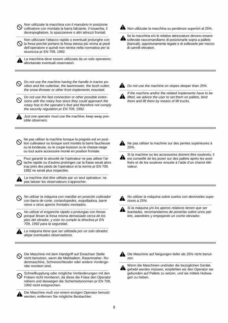
Non utilizzate la macchina con il manubrio in posizione coltivatore con montata la barra falciante, il tosaerba, il decespugliatore, lo spazzaneve o altri attrezzi frontali.________________________________________________________________________
Non utilizzare l’attacco rapido o eventuali prolunghe con la fresa perché portano la fresa stessa più vicina ai piedi dell’operatore e quindi non rientra nella normativa per la sicurezza pr EN 709, 1992.________________________________________________________________________
La macchina deve essere utilizzata da un solo operatore; allontanate eventuali osservatori.
Non utilizzate la macchina su pendenze superiori al 25%.________________________________________________________________________
Se la macchina e/o le relative attrezzature devono essere sollevate raccomandiamo di posizionarle sopra a pallets (bancali), opportunamente legate e di sollevarle per mezzo di carrelli elevatori.
Do not use the machine having the handle in tractor po- sition and the cutterbar, the lawnmower, the bush-cutter, the snow-thrower or other front implements mounted.________________________________________________________________________
Do not use the fast connection or other possible exten- sions with the rotary hoe since they could approach the rotary hoe to the operator’s feet and therefore not comply the security regulation pr EN 709, 1992.________________________________________________________________________
Just one operator must use the machine; keep away pos- sible observers.
Do not use the machine on slopes deeper than 25%.________________________________________________________________________
If the machine and/or the related implements have to be lifted, we advice the user to set them on pallets, bind them and lift them by means of lift trucks.
Ne pas utiliser la machine lorsque la poignée est en posi- tion cultivateur ou lorsque sont montés la barre faucheuse ou la tondeuse, ou le coupe-buisson ou le chasse-neige ou tout autre accessoire monté en position frontale.________________________________________________________________________
Pour garantir la sécurité de l’opérateur ne pas utiliser l’at- tache rapide ou d’autres prolonges car la fraise serait alors trop près des pieds de l’opérateur et la norme pr EN 709, 1992 ne serait plus respectée.________________________________________________________________________
La machine doit être utilisée par un seul opérateur; ne pas laisser les observateurs s’approcher.
Ne pas utiliser la machine sur des pentes supérieures à 25%. ________________________________________________________________________
Si la machine ou les accessoires doivent être soulevés, il est conseillé de les poser sur des pallets après les avoir fixés et de les soulever ensuite à l’aide d’un chariot élé- vateur.
No utilizar la máquina con manillar en posición cultivador con barra de corte, cortacéspedes, esquilladora, barre nieve o otros aperos frontales montados.________________________________________________________________________
No utilizar el enganche rápido o prolungas con fresas porqué llevan la fresa misma demasiado cerca de los pies del obrador, y esto no cumple la directiva pr EN 709, 1992 para la seguridad.________________________________________________________________________
La máquina tiene que ser utilizada por un solo obrador; alejar eventuales observadores.
No utilizar la máquina sobre suelos con desniveles supe- riores a 25%.________________________________________________________________________
Si la máquina y/o los aperos relativos tienen que ser leantadas, recomandamos de ponerlas sobre unos pal- lets, atandoles y empejando un coche elevador.
Die Maschine mit dem Handgriff auf Einachser Stelle nicht benutzen, wenn die Mahbalken, Rasenmaher, Ro- denmaschine, Schneeschleuder oder andere Vorderge- räte montiert sind.________________________________________________________________________
Schnellkupplung oder mögliche Verländerungen mit den Fräsen nicht montieren, da diese die Fräse den Operator nähern und deswegen die Sicherheitsnormen pr EN 709, 1992 nicht entsprechen.________________________________________________________________________
Die Maschine muß von einem enzigen Operator benutzt werden; entfernen Sie mögliche Beobachter.
Die Maschine auf Neigungen tiefer als 25% nicht benut- zen.________________________________________________________________________
Wenn die Maschinen und/oder die bezüglichen Geräte gehebt werden müssen, empfehlen wir den Operator sie gebunden auf Pallets zu setzen, und sie mittels Hubwa- gen zu heben.

INFORMAZIONI PER L’OPERATORE(1) LAeq PRESSIONE ACUSTICA: Valori espressi in dB(A) equi-valenti - (2) LwA POTENZA ACUSTICA: Valori espressi in dB(A)- (3) m/sec² VIBRAZIONE: Valore quadratico medio ponderatosecondo ISO 5349 alle stegole; per motocoltivatori: con attrezzodisinserito e macchina ferma UNI EN 709; per motofalciatrici con
A = B = C = D = E =
A = B = C = D = E =
A = B = C = D = E =
A = B = C = D = E =
(E)
6
MOTORI (A) BENZINA (B) DIESEL (C) Valori (D) Modelli
LAeq(1)
LwA(2)
m/sec²(3)
LAeq(1)
LwA(2)
m/sec²(3)
10
barra in funzione e macchina in movimento su terreno, secondopr EN 12733. - (*) Se LAeq è minore di 85 dB(A) il livello di poten-za acustica (LwA) non occorre indicarlo.
ATTENZIONE, PERICOLO: per l’utilizzo di macchine che superano gli 85 dB(A) di LAeq, l’operatore deve indossare adeguati mezzi di protezione acustici (cuffie).
INFORMATIONS FOR THE USER
MOTORS
GASOLINE
DIESEL
VALUES
MODELS
(1) LAeq ACUSTIC PRESSURE: Values expressed in equivalentdB(A) - (2) LwA ACUSTIC POWER: Values expressed in dB(A) -(3) m/sec² VIBRATION: average square value calculated accor-ding to ISO 5349 at handlebars; for tractors: with disengaged devi-ce and stillstanding machine according to UNI EN 709; for motor-mowers: with operating cutterbar and machine moving on groundaccording to pr EN 12733.(*) When LAeq is lower than 85 dB(A) itis not necessary to indicate the acustic power level (LwA).
ATTENTION, DANGER: when using machines emitting a LAeq higher than 85 dB(A), the user must wear fitted acustic protections means (guard).
INFORMATIONS POUR L’OPÉRATEUR
MOTEUR
ESSENCE
DIESEL
MESURES
MODELES
(1) LAeq PRESSION ACOUSTIQUE: valeurs exprimées en dB(A)équivalent. (2) LwA PUISSANCE ACOUSTIQUE: valeurs expri-mées en dB(A) (3) m/sec² VIBRATION: valeur quadratique moyen-ne pondérée suivant ISO 5349 aux poignées; pour motoculteurs:sans outillage à l’arrêt suivant UNI EN 709; for motofaucheuses:avec barre de fauchage et machine en mouvement sur le terrain,suivant pr EN 12733. (*) Quand LAeq est inférieur à 85 dB(A) iln’est pas necessaire d’indiquer la puissance acoustique (LwA).
ATTENTION, DANGER: Lors de l’utilisation de machines supérieures à 85 dB(A) de LAeq, l’opérateur doit porter un casque de protection acoustique.
INFORMACCIONES PARA EL UTILIZADOR
MOTORES
GASOLINA
DIESEL
VALORES
MODELES
(1) LAeq PRÉSION ACÚSTICA: valores exprimidos en dB(A)equivalentes (2) LwA POTENCIA ACÚSTICA: Valores exprimidosen dB(A) - (3) m/sec² VIBRACIÓN: Valor cuadrático medio ponde-rado según ISO5349 a las estevas; por motocultivadores: con ape-ro descebado y máquina parada según UNI EN 709; por motocor-tacéspedes: con barra en actividad y máquina en movimiento so-bre terreno, según pr EN 12733. (*) Si LAeq es inferior a 85 dB(A)el nivel de potencia acústica (LwA) no tiene que ser indicado.
ATENCIÓN, PELIGRO: para utilizar máquinas que sobre- pasan los 85 dB(A) de LAeq, el utilizador debe llevar medios de protección acústica adecuados (cofias).
INFORMATIONEN FÜR DEN OPERATOR
MOTOREN
BENZIN
DIESEL
WERTE
MODELLEN
(1) LAeq ACUSTISCHES DRUCK: Werte ausgedrückt in dB(A)Äquivalenten. (2) LwA ACUSTISCHE LEISTUNG: Werte ausge-drückt in dB(A). (3) m/sec² SCHWINGUNG: Quadratwert berech-net nach ISO 5349 auf die Sterzen; für Einachser: mit abgeschal-tetem Arbeitsgerät und stiller maschine nach UNI EN 709; für Mo-tormähern: mit funktionierenden Mähbalken auf dem Boden nachpr EN 12733.(*) Wenn LAeq niedriger als 85 dB(A) ist, brauchtman nicht das Niveau der akustischen Leistung zu zeigen (LwA).
ACHTUNG, GEFAHR: Um Maschine, die ein Wert höher als 85 dB(A) von LAeq haben zu benutzen muß den Verbraucher geeignete Mittel für akustische Schutz trägen (Kopfhörer).
50/ 852 / 853740
746 / 948
8382,982,9
(*)(*)(*)
11,741,31,3
91.290,390,3
101.7108108
15.93,73,7
11
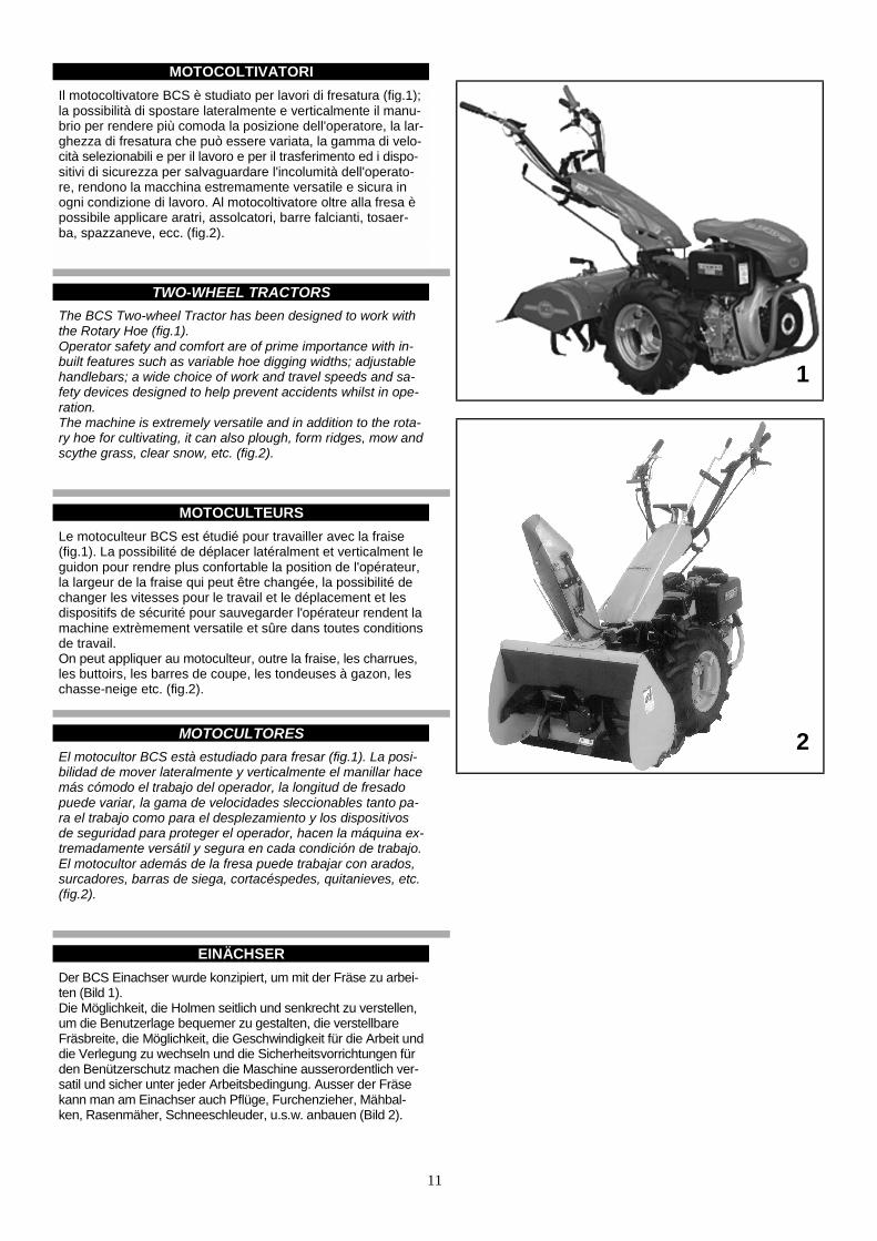
MOTOCOLTIVATORIIl motocoltivatore BCS è studiato per lavori di fresatura (fig.1);la possibilità di spostare lateralmente e verticalmente il manu-brio per rendere più comoda la posizione dell'operatore, la lar-ghezza di fresatura che può essere variata, la gamma di velo-cità selezionabili e per il lavoro e per il trasferimento ed i dispo-sitivi di sicurezza per salvaguardare l'incolumità dell'operato-re, rendono la macchina estremamente versatile e sicura inogni condizione di lavoro. Al motocoltivatore oltre alla fresa èpossibile applicare aratri, assolcatori, barre falcianti, tosaer-ba, spazzaneve, ecc. (fig.2).
TWO-WHEEL TRACTORS The BCS Two-wheel Tractor has been designed to work withthe Rotary Hoe (fig.1). Operator safety and comfort are of prime importance with in-built features such as variable hoe digging widths; adjustablehandlebars; a wide choice of work and travel speeds and sa-fety devices designed to help prevent accidents whilst in ope-ration.The machine is extremely versatile and in addition to the rota-ry hoe for cultivating, it can also plough, form ridges, mow andscythe grass, clear snow, etc. (fig.2).
MOTOCULTEURSLe motoculteur BCS est étudié pour travailler avec la fraise(fig.1). La possibilité de déplacer latéralment et verticalment leguidon pour rendre plus confortable la position de l'opérateur,la largeur de la fraise qui peut être changée, la possibilité dechanger les vitesses pour le travail et le déplacement et lesdispositifs de sécurité pour sauvegarder l'opérateur rendent lamachine extrèmement versatile et sûre dans toutes conditionsde travail.On peut appliquer au motoculteur, outre la fraise, les charrues,les buttoirs, les barres de coupe, les tondeuses à gazon, leschasse-neige etc. (fig.2).
MOTOCULTORESEl motocultor BCS està estudiado para fresar (fig.1). La posi-bilidad de mover lateralmente y verticalmente el manillar hacemás cómodo el trabajo del operador, la longitud de fresadopuede variar, la gama de velocidades sleccionables tanto pa-ra el trabajo como para el desplezamiento y los dispositivosde seguridad para proteger el operador, hacen la máquina ex-tremadamente versátil y segura en cada condición de trabajo.El motocultor además de la fresa puede trabajar con arados,surcadores, barras de siega, cortacéspedes, quitanieves, etc.(fig.2).
EINÄCHSERDer BCS Einachser wurde konzipiert, um mit der Fräse zu arbei-ten (Bild 1).Die Möglichkeit, die Holmen seitlich und senkrecht zu verstellen,um die Benutzerlage bequemer zu gestalten, die verstellbareFräsbreite, die Möglichkeit, die Geschwindigkeit für die Arbeit unddie Verlegung zu wechseln und die Sicherheitsvorrichtungen fürden Benützerschutz machen die Maschine ausserordentlich ver-satil und sicher unter jeder Arbeitsbedingung. Ausser der Fräsekann man am Einachser auch Pflüge, Furchenzieher, Mähbal-ken, Rasenmäher, Schneeschleuder, u.s.w. anbauen (Bild 2).
1
2

12
MOTOFALCIATRICILe motofalciatrici BCS (fig.3) a barra centrale sono particolar-mente adatte per lo sfalcio. Il loro peso ridotto, la frizione acomando manuale, il manubrio regolabile in altezza e montatosu sospensione elastica antivibrante, i dispositivi di sicurezzarendono la macchina estremamente maneggevole e sicura.Oltre alla barra falciante, alle motofalciatrici è possibile appli-care tosaerba, spazzaneve, frese, ecc. (fig.4).
MOTOR MOWERS The motor-mowers BCS (fig.3) with centrally mounted cutterbars are particularly suitable for moving. Their low weight, themanual operated clutch, the anti-vibration handlebar withheight adjustment and the built-in safety devices make thesemachines extremely easy to operate and safe.In addition to the cutter bar for motor mowers it is also pos-sible to operate lawn mower, snow throwers, rotary hoe, etc.(fig.4).
MOTOFAUCHEUSESLes motofaucheuses BCS (fig.3) avec barre centrale sont par-ticulièrement appropriées pour le fauchage. Leur poids réduit,l'embrayage à commande manuelle, le mancheron à hauté re-glable, monté sur une suspension élastique antivibrante et lesdispositifs de sécurité rendent la machine extrèmement ma-niable et sûre même dans les conditions d'utilisation les plusdifficiles.Il est possible de monter sur les motofaucheuse, outre la bar-re de coupe, la tondeuse, le chasseneige, la fraise, etc (fig.4).
MOTOSEGADORASLas motosegadoras BCS (fig.3) con barra central están parti-cularmente indicadas para la siega. Su peso reducido, el em-brague con mando manual, el manillar regulable en alturamontado en suspensión elástica antivibrante y el dispositivode seguridad, convierten extremadamente manejable y segu-ra la máquina.Ademàs de la barra de siega, pueden montarse en motosega-dora, cortacésped, quitanieves, fresa, etc. (fig.4).
MOTORMÄHERDie Motormäher BCS (Bild 3) mit Frontmähbalken sind fürden Schnitt besonders geeignet. Ihr begrenztes Gewicht, diehandbetätigte Kupplung, der Holm mit verstellbarer Höhe,wel-cher auf einer gefederten, vibrationsdämpfenden Aufhängungmontiert sind, sowie die Sicherheitsvorrichtungen machen die-se Maschinen auch unter den schwersten Betriebsbedingun-gen ausserordentlich handlich und sicher.Auf die Motormäher ist es möglich Rasenmäher, Schnee-schleuder, Fräse, u.s.w. ausser dem Mähbalken zu montieren(Bild 4).
13
MONTAGGIO DELLA MACCHINA
1.2 / 1.5 bar (vedi tab.1 pag. 29).
MACHINE ASSEMBLY
page 29).
MONTAGE DE LA MACHINE
1.5 bar (voir table 1 page 29).
MONTAJE DE LA MAQUINA
de 1.2 / 1.5 bar (veer tab.1 pag. 29).
MASCHINEMONTAGE
Seite 29).
14
NORME DI SICUREZZA
GENERAL SAFETY
REGLES DE SECURITE GENERALE
NORMAS DE SEGURIDAD
SICHERHEITSVORSCHRIFTEN
15
16
17
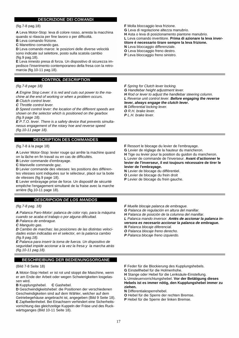
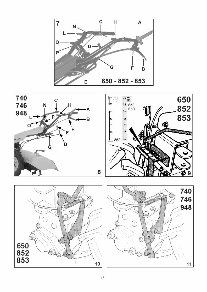
DESCRIZIONE DEI COMANDI(fig.7-8 pag.18)
A Leva Motor-Stop: leva di colore rosso, arresta la macchinaquando si rilascia per fine lavoro o per difficoltà.B Leva comando frizione.C Manettino comando gas.D Leva comando marce: le posizioni delle diverse velocitàsono indicate sul selettore, posto sulla scatola cambio(fig.9 pag.18).E Leva innesto presa di forza. Un dispositivo di sicurezza im-pedisce l'inserimento contemporaneo della fresa con la retro-marcia (fig.10-11 pag.18).
F Molla bloccaggio leva frizione.G Leva di regolazione altezza manubrio.H Asta o leva di posizionamento piantone manubrio.L Leva comando invertitore. Prima di azionare la leva inver-titore é necessario tirare sempre la leva frizione.N Leva bloccaggio differenziale.O Leva bloccaggio freno destro.P Leva bloccaggio freno sinistro.
CONTROL DESCRIPTION (fig.7-8 page 18) A Engine Stop Lever: it is red and cuts out power to the ma-chine at the end of working or when a problem occurs. B Clutch control lever. C Throttle control lever. D Speed control lever: the location of the different speeds areshown on the selector which is positioned on the gearbox(fig.9 page 18). E P.T.O. lever. There is a safety device that prevents simulta-neous engagement of the rotary hoe and reverse speed(fig.10-11 page 18).
F Spring for Clutch lever locking.G Handlebar height adjustment lever.H Rod or lever to adjust the handlebar steering column.L Reverse unit control lever. Before engaging the reverselever, always engage the clutch lever.N Differential locking lever.O R.H. brake lever.P L.H. brake lever.
DESCRIPTION DES COMMANDES(fig.7-8 à la page 18)
A Levier Motor-Stop: levier rouge qui arrête la machine quandon la lâche en fin travail ou en cas de difficultés.B Levier commande d'embrayage.C Manivelle commande gaz.D Levier commande des vitesses: les positions des différen-tes vitesses sont indiquées sur le sélecteur, placé sur la boitede vitesses (fig.9 page 18).E Levier embrayage prise de force. Un dispositif de sécuritéempêche l'engagement simultané de la fraise avec la marchearrière (fig.10-11 page 18).
F Ressort le blocage du levier de l'embrayage.G Levier de réglage de la hauteur du mancheron.H Tige ou levier pour la position du guidon du mancheron.L Levier de commande de l'inverseur. Avant d'actionner lelevier de l'inverseur, il est toujours nécessaire de tirer lelevier de l'embrayage.N Levier de blocage du différentiel.O Levier de blocage du frein droitP Levier de blocage du frein gauche.
DESCRIPCION DE LOS MANDOS(fig.7-8 pag. 18)
A Palanca Paro-Motor: palanca de color rojo, para la máquinacuando se acaba el trabajo o por alguna dificultad.B Palanca de embrague.C Manguito gas.D Cambio de marchas: las posiciones de las distintas veloci-dades estan indicadas en el selector, en la palanca cambio(fig.9 pag.18).E Palanca para inserir la toma de fuerza. Un dispositivo deseguridad impide accionar a la vez la fresa y la marcha atrás(fig.10-11 pag.18).
F Muelle blocaje palanca de embrague.G Palanca de regulación en altura del manillar.H Palanca de posición de la columna del manillar.L Palanca mando inversor. Antés de accionar la palanca in-versora es necesario accionar la palanca de embrague.N Palanca blocaje diferencial.O Palanca blocaje freno derecho.P Palanca blocaje freno izquierdo.
BESCHREIBUNG DER BEDIENUNGSORGANE(Bild 7-8 Seite 18)
A Motor-Stop Hebel: er ist rot und stoppt die Maschine, wenner am Ende der Arbeit oder wegen Schwierigkeiten losgelas-sen wird.B Kupplungshebel. C Gashebel.D Geschwindigkeitshebel: die Positionen der verschiedenenGeschwindigkeiten sind auf dem Wähler, welcher auf demGetriebegehäuse angebracht ist, angegeben (Bild 9 Seite 18).E Zapfwellenhebel. Bei Einachsern verhindert eine Sicherheits-vorrichtung das gleichzeitige Kuppeln der Fräse und des Ruck-wärtsganges (Bild 10-11 Seite 18).
F Feder für die Blockierung des Kupplungshebels.G Einstellhebel für die Holmenhohe.H Stange oder Hebel für die Lenksäule-Einstellung.L Umsteuervorrichtungshebel. Vor der Betätigung diesesHebels ist es immer nötig, den Kupplungshebel immer zuziehen.N Differentialesperrehebel.O Hebel für die Sperre der rechten Bremse.P Hebel für die Sperre der linken Bremse.
18

19
APPLICAZIONE ATTREZZIGli attrezzi si applicano direttamente alla flangiatura A (fig.12)oppure interponendo l’attacco rapido C (fig.13).
E’ necessario che i dadi D (fig.13) che fissano l’attrezzo allamacchina siano ben serrati.
Il rimorchio a ruote libere ed il carrello di trasferimento si attac-cano al gancio di traino E (fig.12).
Per applicare ai motocoltivatori la barra falciante, il tosaerba,lo spazzaneve, ecc., ed alle motofalciatrici fresa, assolcatori,aratri, è necessario ruotare il manubrio di 180°.
Prima di fare questo, vanno sganciate le aste di comando mar-ce D e presa di forza E dai supporti, tirare la leva di posiziona-mento piantone manubrio H e girare (fig.7-8 pag.18).
Reinserirla una volta scelta la posizione ideale del manubrio.
Girato il manubrio, le aste vanno reinserite nei supporti.
IMPLEMENT ASSEMBLYImplements are mounted directly to the flange A (fig.12) or fit-ting the attachment the quick hitch C (fig.13).
It is necessary that nuts D (fig.13) which fasten the implementto the machine are well tightened.
The free wheel trailer and the travel sulky are mounted to thetow hook E (fig.12).
To mount to the two-wheel tractors the cutter bar, lawn mower,snow thrower, etc., and to the motor mowers the rotary hoe, rid-gers and ploughs, it is necessary to turn the handlebar of 180°.
Before making that, you must release the speed D and P.T.O.controls rods E from supports, pull lever for handlebarsteering column position H and turn (fig.7-8 pag.18).
Insert it again after choosing the ideal position of the handle-bar.
After turning the handlebar, rods must be inserted again intothe supports.
MONTAGE OUTILSLes outils sont montés directement à la bride A (fig.12) oubien entreposant l’attache rapide C (fig.13).
Les écrous D (fig.13) qui fixent l’outil à la machine doiventêtre bien serrés.
Le remorque à roues libres et le sulky doivent être attachés aucrochet de traction E (fig.12).
Pour appliquer aux motoculteurs la barre de coupe, la tondeu-se, le chasse-neige, etc., et la motofaucheuse la fraise, lesbutteurs, les charrues, il est nécessaire de tourner le manche-ron de 180°.
Avant de faire celà, on doit décrocher des supports les tiges decommande des marches D et prise de force E, tirer le levierpour la mise en position du guidon H et tourner (fig.7-8 pag.18).
Le réinsérer après avoir choisi la position idéale du manche-ron.
Après avoir tourné le mancheron, les tiges doivent être réinsé-rées dans les supports.
APLICACION APEROSLos aperos se aplican directamente a la flangia A (fig.12) obien poniendo entre un enganche rápido C (fig.13).
Es necesario que las tuercas D (fig.13) que fijan el apero a lamáquina esten bien apretadas.
El remolque de arrastre y el carro de transporte se montan alenganche de arrastre E (fig.12).
Para acoplar al motocoltor la barra de siega, el cortacésped,el quitanieves, etc., y a la motosegadoras la fresa, surcador,arados, es necesario girar el manillar 180°.
Antes de hacer esto, cuando se desengancha el asta del man-do marchas D y la toma de fuerza E del supporte, tirar de lapalanca de posición de la columna del manillar H y girar(fig.7-8 pag.18).
Reinserirla una vez encontrada la posición ideal del manillar.
Girando el manillar, las astas se meterán en los soportes.
MONTAGE DER ARBEITSGERATEDie Arbeitsgeräte werden mittels Flansch A (Bild 12) oder mit-tels Schnell-anschluß C (Bild 13) zwischen Arbeitsgerät undMaschine direkt montiert.
Die Muttern D (Bild 13), welche das Arbeitsgerät an der Maschi-ne befestigen, müssen gut angezogen werden. Der Anhängermit Freilaufradern und der Fahrersitz werden mittels ZughakenE (Bild 12) angekuppelt.
Um an den Einachsern den Mähbalken, Schneeschleuder, Ra-senmäher, etc., und an den Motormäher Fräse, Furchenzieheroder Pflüge zu montieren, ist es nötig, den Holm um 180° zudrehen.
Vor dieser Arbeit muß man Geschwindigkeits D und Zapfwel-lenstange E von den Lagern auskuppeln, Hebel für die Holmen-Einstellung H ziehen und gegen den Uhrzeigersinn drehen(Bild 7-8 Seite 18).
Nachdem Sie den gewunschte Holmenstellung gewählt haben,schalten Sie den Hebel wieder.
Nach Drehen des Holmens müssen die Stangen wieder in ihreLager geschaltet werden.

20
17/1

21
APPLICAZIONE ATTREZZI PRESA DI POTENZA
Ruotato il manubrio di 180° si hanno a disposizione 3 marceavanti che tirando la leva rossa L (fig.7-8 pag.18) posta sulmanubrio diventano retromarce.La 4a velocità in questa condizione di lavoro non può essereinserita.
É a 3 denti con innesto frontale. La rotazione è destra, indi-pendente dal cambio, vincolata alla velocità del motore (990giri/1’ a 3600 giri/1’ del motore).
Per lo schema e le dimensioni della flangiatura vedi fig.17/1.
IMPLEMENT ASSEMBLY P.T.O. If you turn the handlebar of 180° you get three forward speeds,that, pulling red lever L (fig.7-8 page 18) on the handlebar,become reverse speeds. The 4th speed cannot be engaged in this condition of work.
It is a front locking 3-teeth implement. It rotates right, indipen-dently from the gear, and depending on the motor speed (990rev/1’ at 3600 rev/1’ of the motor).
For the scheme and the flange dimension, please refer tofigure 17/1.
MONTAGE OUTILS PRISE DE PUISSANCE
En tournant le mancheron de 180°, on dispose de 3 marchesavant qui, en tirant le levier rouge L (fig.7-8 à la page 18)placé sur le mancheron, deviennent marches arrières.La 4ème vitesse dans cette condition de travail ne peut pasêtre embrayée.
A 3 dents avec insertion frontale rotation à droite, indépen-dente du changement de vitesse, est liée à la vitesse du mo-teur (990 tours/1’ à 3600 tours/1’ du moteur).
Schéma et dimensions des brides (fig.17/1).
APLICACION APEROS TOMA DE FUERZA
Girando el manillar 180° se dispone de 3 marchas adelanteque tirando de la palanca roja L (fig.7-8 pag.18) del manillarse convierte en marcha atrás.La 4a velocidad en estas condiciones de trabajo no puedeaccionarse.
Es a tres dientes con conexión frontal. La rotación es hacia laderecha, indipendiente del cambio, vinculada a la velocidaddel motor (990 giros/1’ a 3600 giros/1’ del motor).
Por el esquema y las dimensiones de la flangia ver fig.17/1.
MONTAGE DER ARBEITSGERATE ZAPFWELLE
Erhalten Sie durch Drehen des Holmen 3 Vorwärtsgänge, wel-che zu Rüchwärtsgängen werden, wenn Sie den roten Hebel L(Bild 7-8 Seite 18) auf dem Holmen ziehen.Der 4 Gang kann nicht in diese Arbeitsbedingung eingeschaltetwerden.
Zähnen vordere Einkupplung Zapfwelle. Das Drehen ist nachrecht, unabhängig vom Getriebe, je nach der Geschwindigkeit(990 Dreh./1’ bei 3600 Dreh./1’ des Motors).
Siehe Bild 17/1 für das Schema und die Abmessungen derFlansche.

22
CONTROLLI DA ESEGUIRE PRIMA DI AVVIARE LAMACCHINA
Seguendo le istruzioni contenute nel libretto uso e manuten-zione del motore, controllare il livello dell’olio. E’ bene lavora-re con il livello dell’olio al massimo, specialmente quando silavora su pendenze, per avere così una sicura lubrificazione.In caso di rabboccamento dell’olio usare qualità e densità in-dicate nel libretto stesso.
Attenzione: non superare mai il livello di olio max previ-sto dal costruttore.
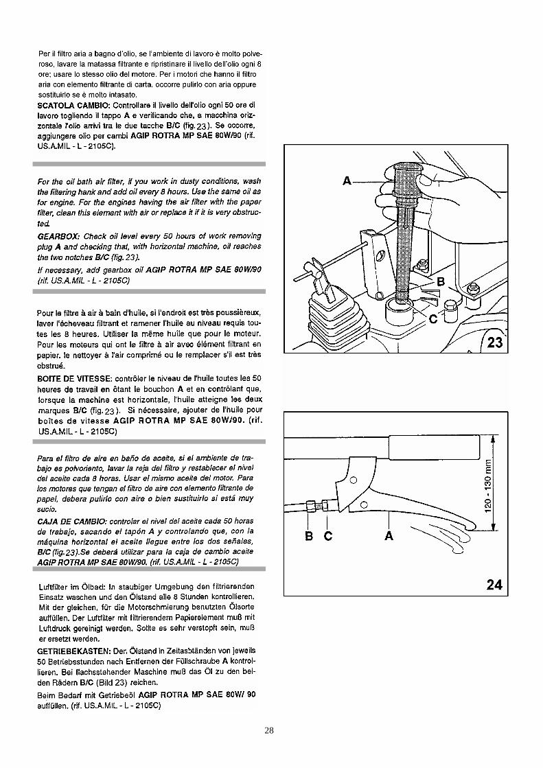
Controllare il livello dell’olio nella scatola cambio, sfilando il tap-po A (fig.18) e verificare che il livello sia compreso fra le duetacche B e C.In caso di rabbocco aggiungere olio AGIP ROTRA MP SAE80W/90 (rif. US.A.MIL. - L - 2105C) (per elevate pressioni).Riempire il serbatoio di carburante, non fare mai rifornimentocon il motore in moto, utilizzate un imbuto con filtro a rete inmodo da trattenere eventuali impurità.Completate queste operazioni la macchina è pronta per essereavviata.
CHECKS BEFORE STARTING THE MACHINE Check oil level, following the instructions in the engine opera-ting manual. To ensure correct lubrication, especially whenworking on slopes, the oil level should be maximum. Shouldthe oil spill off, use the quality and density as prescribed in thesame operating manual. Attention: never exceed the max. oil level established bythe manufacturer.
Check oil level in the gearbox through oil plug A (fig.18), verifythat the level is between the two grooves B and C.If necessary add oil AGIP ROTRA MP SAE 80W/90 (rif. US.A.MIL. - L - 2105C) (for high pressure).Fill tank with fuel using a funnel with a mesh filter to eliminateimpurities.Never fill the tank whilst engine is running.After having performed these operations the machine is readyto be started.
CONTROLES A EFFECTUER AVANT DEDEMARRER LA MACHINE
En suivant les instructions données dans le manuel du moteur,contrôler le niveau de l’huile. Travailler avec le niveau de l’huileau maximum, particulièrement quand on travaille sur des pen-tes, pour avoir une lubrification sûre.En cas de remplissage, utiliser une huile en quantité et densitéconforme a celle indiquée dans le manuel.
Ne jamais dépasser le niveau de l’huile maximum prévupar le constructeur.
Contrôler le niveau de l’huile dans la boîte de vitesses en ôtantle bouchon A (fig.18) et en vérifiant que le niveau de l’huile soitcompris entre le deux marques B et C.Si nécessaire, ajouter de l’huile AGIP ROTRA MP SAE 80W/90(rif. US.A.MIL. - L - 2105C) (pour pressions élevées).Remplir le réservoir de carburant, mais jamais avec le moteuren marche.Utilisez un entonnoir avec filtre en tamis de façon à retenird’éventuelles impurités. Ces operations complétées, la machineest prête pour être démarrée.
CONTROLES A EFECTUAR ANTES DE PONER ENMARCHA LA MAQUINA
Siguiendo las operacciones contenidas en el librito de uso ymanutención del motor, controlar el nivel de aceite. Es acon-sejable trabajar con el nivel de aceite al máximo, especial-mente cuando se trabaja en pendientes, para tener así unasegura lubrificación.En caso de añadir aceite usar la calidad y densidad indicadaen el mismo librito.
¡Atención!: no se debe superar nunca el nivel màximo deaceite indicado por el fabricante.
Controlar el nivel de aceite de la caja de cambio, retirando eltapón A (fig.18) y verificar si el nivel llega entre las dos mar-cas B y C.En caso de tener que añadir aceite, usar AGIP ROTRA MPSAE 80W/90 (rif. US.A.MIL. - L - 2105C) (para elevadas pre-siones).Rellenar el depósito del carburante, no lo haga nunca con elmotor funcionando, utilice un embudo con filtro de reja pararetener cualquier impureza. Hecha esta operación, la máqui-na estará a punto para su funcionamiento.
VOR DEN INBETRIEBNAHME VORZUNEHMENDEKONTROLLEN
Ölstand im Motor kontrollieren (siehe die entsprechenden Be-triebsanleitung). Das Öl sollte sich am hochsten Stand beson-ders am Hang befinden, um eine sichere Schmierung zu ge-währleisten.Bei Bedarf mit Öl der vom Hersteller angegebenen Qualitätund Viskosität auffüllen.
Achtung: niemals den vom Hersteller vorgesehenen Öl-höchstand überschreiten.
Den Ölstand im Getriebekasten nach Entfernen der Verschrau-bung A (Bild 18) prüfen. Der Ölstand muß zwischen den beidenMarkierungen B und C liegen. Bei Bedarf mit Öl AGIP ROTRAMP AE 80W/90 (rif. US.A.MIL-L- 2105C) auffüllen (Hochdruck).Den Tank mit Kraftstoff auffüllen, niemals mit laufendem Motorfüllen.Das Benzin muß immer durch einen Trichter mit Netzfilter einge-füllt werden, damit keine Fremdkörper in das Kraftstoffsystemgelangen konnen. Die Maschine ist auf diese Weise arbeitsbe-reit.
23
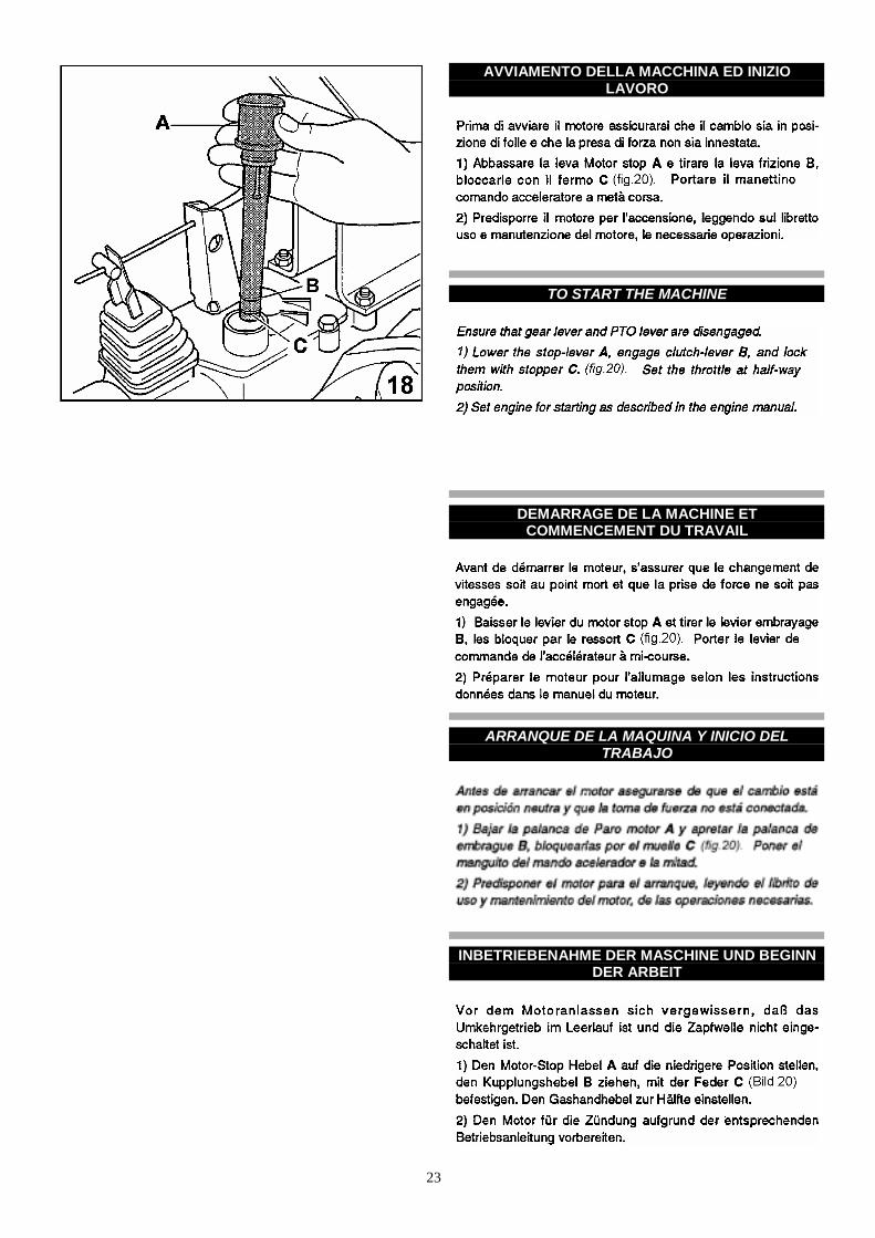
AVVIAMENTO DELLA MACCHINA ED INIZIOLAVORO
TO START THE MACHINE
DEMARRAGE DE LA MACHINE ETCOMMENCEMENT DU TRAVAIL
ARRANQUE DE LA MAQUINA Y INICIO DELTRABAJO
INBETRIEBENAHME DER MASCHINE UND BEGINNDER ARBEIT
24
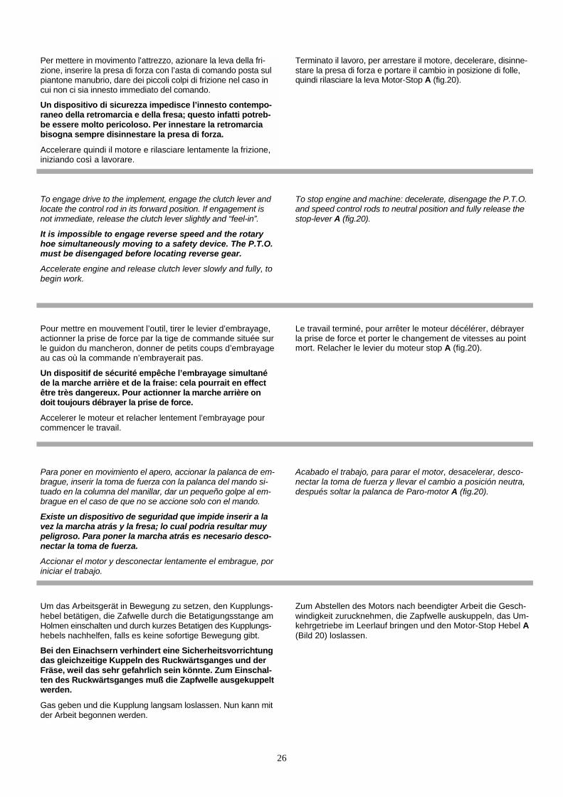
3) Afferrare la maniglia dell’avviamento, tirarla dolcemente finoa che si aggancia l’arpionismo, quindi appoggiare il piede (fig.21) e dare un energico strattone.
La maniglia va afferrata con UNA SOLA MANO, per evita-re contraccolpi del motore che possono ferire l’operatore.
Una volta che il motore è avviato, lasciarlo girare a vuoto qual-che minuto per dar tempo all’olio di raggiungere tutti gli organiin movimento. Impugnare il manubrio e serrare la leva frizioneper sganciare la molla di ritegno; fare attenzione a non rila-sciare la leva Motor-Stop A (fig.20) perchè la macchina sifermerà all’istante.
Innestare la marcia desiderata, portando l’asta comando cam-bio in corrispondenza della marcia prescelta.
Nel caso che la marcia non si innestasse subito dare dei pic-coli colpi di frizione. Una volta innestata la marcia rilasciare lafrizione lentamente, fino a che la macchina si sarà messa inmovimento.
3) Slowly pull the starting handle until the hooking system isengaged, then give a strong pull placing the foot (fig.21). The rope handle must always be grasped with ONE HANDONLY, to prevent the engine “kicking back”. When the engine has started, allow it to run idle for some mi-nutes to allow oil to lubricate all moving parts. Grip the clutchlever on the handlebars to allow the locking stop spring to re-lease, making sure not to fully release the stop-lever A(fig.20) which will stop the engine running.
Engage and locate the speed control rod to the desired speedposition.
If the gear does not engage immediately release the clutchlever slightly and “feel-in”. When the gear is engaged, releasethe clutch lever slowly and fully until the machine starts.
3) Prendre la poignée du lanceur, la tirer doucement jusqu’àl’accrocher à l’encliquetage puis appuyer le pied (fig.21) et tirerénergiquement.
La poignée doit être tenue d’UNE SEUL MAIN pour éviterd’eventuels contre-coups du moteur qui peuvent blesserl’opérateur.
Une fois le moteur allumé, le laisser tourner à vide pendantquelques minutes pour permettre à l’huile d’atteindre tous lesorganes en mouvement. Prendre le mancheron et serrer le le-vier d’embrayage pour décrocher le ressort d’arrêt: faire atten-tion à ne pas relacher le levier du motor stop A (fig.20) carla machine s’arrêtera à l’instant.
Enclencher la marche souhaitée en amenant la tige decommande de la boîte de vitesses en correspondance de lavitesse désirée.
Au cas où la vitesse n’entrerai pas tout de suite, donner despetits coups d’embrayage. Une fois mise en marche,embrayer lentement jusqu’à ce que la machine soit entrée enmouvement.
3) Coger la manecilla de arranque, tirar de ella suavementehasta que se enganche al gancho, después apoyar los pies(fig.21) y dar un fuerte tirón.
El puño debe cogerse con UNA SOLA MANO, para evitarcontragolpes del motor que podrían herir al operador.
Una vez el motor está en marcha, dejarlo rodar durante unosminutos para dar tiempo a que el aceite llegue a todos los ór-ganos de movimiento. Empuñar el manillar y apretar la palan-ca del embrague para enganchar el muelle del freno; presteatención en no dejar la palanca de Paro-motor A (fig.20)porque la máquina se parará al instante.
Escoja la marcha deseada, llevando la palanca de cambio ala marcha correspondiente.
En el caso que la marcha no entre, dé un pequeño golpe alembrague. Una vez puesta en marcha deje el embraguelentamente, hasta que la máquina se ponga en movimiento.
3) Den Anlassergriff sanft ziehen, bis die Rastvorrichtung ein-rastet. Dann den Fuß wie im (Bild 21) gezeigt aufsetzen undden Motor mit einem Ruck anwerfen.
In beiden Fallen darf der Anlassergriff immer NUR MIT EINERHAND betatigt werden, um Verletzungen beim Ruckschla-gen des Motors zu vermeiden.
Seilrolle anlassen. Wenn der Motor anspringt, ihn einige Minu-ten leerlaufen lassen, damit das Schmieröl zu den beweglichenMaschinenteilen gelangen kann.Den Holmen ergreifen und denKupplungshebel anziehen, um die Haltefeder zu lösen: DerMotor-Stop Hebel A (Bild 20) muß nicht losgelassen wer-den, sonst wird der Motor sofort abstellen.
Zum Einlegen des gewunschten Ganges die Gangschaltstangeauf den vorgewahlten Gang einstellen. Wenn der Gang nichtsofort einrastet, durch kurzes Betatigen des Kupplungshebelsnachhelfen.
Sobald der gewünschte Gang eingerückt ist, Kupplungshebellangsam loslassen, bis sich die Maschine Bewegung setzt.
25
26
Per mettere in movimento l’attrezzo, azionare la leva della fri-zione, inserire la presa di forza con l’asta di comando posta sulpiantone manubrio, dare dei piccoli colpi di frizione nel caso incui non ci sia innesto immediato del comando.
Un dispositivo di sicurezza impedisce l’innesto contempo-raneo della retromarcia e della fresa; questo infatti potreb-be essere molto pericoloso. Per innestare la retromarciabisogna sempre disinnestare la presa di forza.
Accelerare quindi il motore e rilasciare lentamente la frizione,iniziando così a lavorare.
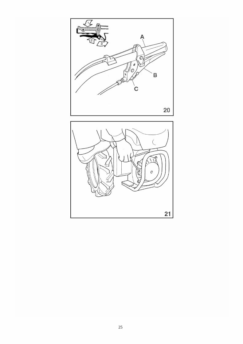
Terminato il lavoro, per arrestare il motore, decelerare, disinne-stare la presa di forza e portare il cambio in posizione di folle,quindi rilasciare la leva Motor-Stop A (fig.20).
To engage drive to the implement, engage the clutch lever andlocate the control rod in its forward position. If engagement isnot immediate, release the clutch lever slightly and “feel-in”.
It is impossible to engage reverse speed and the rotaryhoe simultaneously moving to a safety device. The P.T.O.must be disengaged before locating reverse gear.
Accelerate engine and release clutch lever slowly and fully, tobegin work.
To stop engine and machine: decelerate, disengage the P.T.O.and speed control rods to neutral position and fully release thestop-lever A (fig.20).
Pour mettre en mouvement l’outil, tirer le levier d’embrayage,actionner la prise de force par la tige de commande située surle guidon du mancheron, donner de petits coups d’embrayageau cas où la commande n’embrayerait pas.
Un dispositif de sécurité empêche l’embrayage simultanéde la marche arrière et de la fraise: cela pourrait en effectêtre très dangereux. Pour actionner la marche arrière ondoit toujours débrayer la prise de force.
Accelerer le moteur et relacher lentement l’embrayage pourcommencer le travail.
Le travail terminé, pour arrêter le moteur décélérer, débrayerla prise de force et porter le changement de vitesses au pointmort. Relacher le levier du moteur stop A (fig.20).
Para poner en movimiento el apero, accionar la palanca de em-brague, inserir la toma de fuerza con la palanca del mando si-tuado en la columna del manillar, dar un pequeño golpe al em-brague en el caso de que no se accione solo con el mando.
Existe un dispositivo de seguridad que impide inserir a lavez la marcha atrás y la fresa; lo cual podria resultar muypeligroso. Para poner la marcha atrás es necesario desco-nectar la toma de fuerza.
Accionar el motor y desconectar lentamente el embrague, poriniciar el trabajo.
Acabado el trabajo, para parar el motor, desacelerar, desco-nectar la toma de fuerza y llevar el cambio a posición neutra,después soltar la palanca de Paro-motor A (fig.20).
Um das Arbeitsgerät in Bewegung zu setzen, den Kupplungs-hebel betätigen, die Zafwelle durch die Betatigungsstange amHolmen einschalten und durch kurzes Betatigen des Kupplungs-hebels nachhelfen, falls es keine sofortige Bewegung gibt.
Bei den Einachsern verhindert eine Sicherheitsvorrichtungdas gleichzeitige Kuppeln des Ruckwärtsganges und derFräse, weil das sehr gefahrlich sein könnte. Zum Einschal-ten des Ruckwärtsganges muß die Zapfwelle ausgekuppeltwerden.
Gas geben und die Kupplung langsam loslassen. Nun kann mitder Arbeit begonnen werden.
Zum Abstellen des Motors nach beendigter Arbeit die Gesch-windigkeit zurucknehmen, die Zapfwelle auskuppeln, das Um-kehrgetriebe im Leerlauf bringen und den Motor-Stop Hebel A(Bild 20) loslassen.
27
LUBRIFICAZIONE E MANUTENZIONE
LUBRICATION AND MAINTENANCE
LUBRIFICATION ET ENTRETIEN
LUBRICACION Y MANTENIMIENTO
SCHMIERUNG UND WARTUNG
28
29
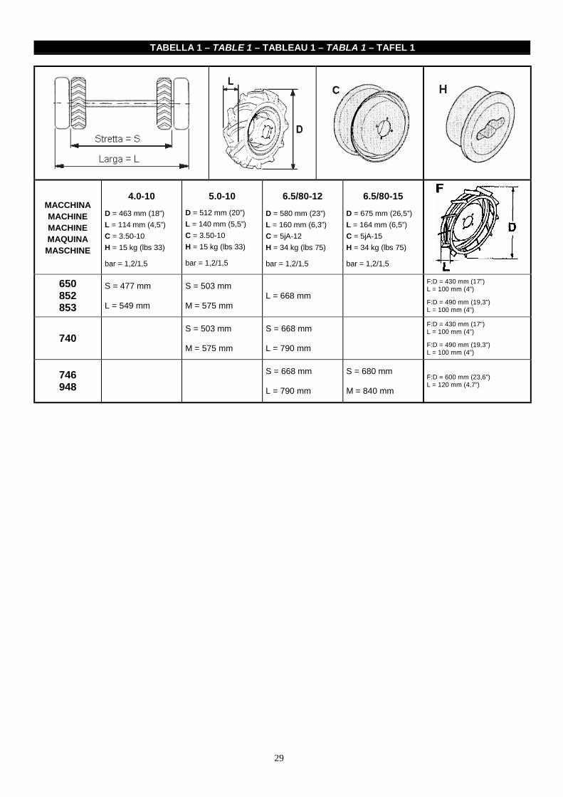
TABELLA 1 – TABLE 1 – TABLEAU 1 – TABLA 1 – TAFEL 1
MACCHINAMACHINEMACHINEMAQUINA
MASCHINE
4.0-10D = 463 mm (18”)L = 114 mm (4,5”)C = 3.50-10H = 15 kg (lbs 33)
bar = 1,2/1,5
5.0-10D = 512 mm (20”)L = 140 mm (5,5”)C = 3.50-10H = 15 kg (lbs 33)
bar = 1,2/1,5
6.5/80-12D = 580 mm (23”)L = 160 mm (6,3”)C = 5jA-12H = 34 kg (lbs 75)
bar = 1,2/1,5
6.5/80-15D = 675 mm (26,5”)L = 164 mm (6,5”)C = 5jA-15H = 34 kg (lbs 75)
bar = 1,2/1,5
650852853
S = 477 mm
L = 549 mm
S = 503 mm
M = 575 mmL = 668 mm
F:D = 430 mm (17”)L = 100 mm (4”)
F:D = 490 mm (19,3”)L = 100 mm (4”)
740S = 503 mm
M = 575 mm
S = 668 mm
L = 790 mm
F:D = 430 mm (17”)L = 100 mm (4”)
F:D = 490 mm (19,3”)L = 100 mm (4”)
746948
S = 668 mm
L = 790 mm
S = 680 mm
M = 840 mmF:D = 600 mm (23,6”)L = 120 mm (4,7”)
30
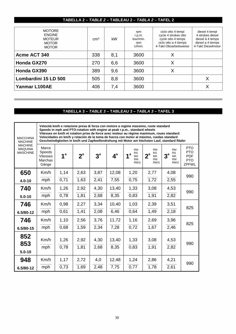
TABELLA 2 – TABLE 2 – TABLEAU 2 – TABLA 2 – TAFEL 2
MOTOREENGINEMOTEURMOTORMOTOR
cm³ kW
rpmr.p.m.
tour/min.rpm
U/min.
ciclo otto 4 tempicycle 4 strokes ottocycle otto 4 temps
ciclo otto a 4 tiemps4-Takt Ottoarbeitsweise
diesel 4 tempi4 strokes dieseldiesel à 4 tempsdiesel a 4 tiemps
4-Takt Dieselmotor
Acme ACT 340 338 8,1 3600 XHonda GX270 270 6,6 3600 XHonda GX390 389 9,6 3600 XLombardini 15 LD 500 505 8,8 3600 XYanmar L100AE 406 7,4 3600 X
TABELLA 3 – TABLE 3 – TABLEAU 3 – TABLA 3 – TAFEL 3
Velocità km/h e rotazione presa di forza con motore a regime massimo, ruote standardSpeeds in mph and PTO-rotation with engine at peak r.p.m., standard wheelsVitesses en km/h et rotation prise de force avec moteur au régime manimum, roues standardVelocidades en km/h y rotación de la toma de fuerza con motor al máximo, ruedas standardGeschwindigkeiten in km/h und Zapfwellendrehung mit Motor am höchsten Lauf, standard Räder
MACCHINAMACHINEMACHINEMAQUINA
MASCHINEMarce
SpeedsVitessesMarchasGänge
1a 2a 3a 4a 1aRMRSMARMRWG
2aRMRSMARMRWG
3aRMRSMARMRWG
PTOPTOPDFPTO
ZPFWL
6504.0-10
Km/h__________
mph1,14
__________
0,712,63
__________
1,633,87
__________
2,4112,08__________
7,551,20
__________
0,752,77
__________
1,724,08
__________
2,55990
7405.0-10
Km/h__________
mph1,26
__________
0,782,92
__________
1,814,30
__________
2,6813,40__________
8,351,33
__________
0,833,08
__________
1,914,53
__________
2,82990
7466.5/80-12
Km/h__________
mph0,98
__________
0,612,27
__________
1,413,34
__________
2,0810,40__________
6,461,03
__________
0,642,39
__________
1,493,51
__________
2,18825
7466.5/80-15
Km/h__________
mph1,10
__________
0,682,56
__________
1,593,76
__________
2,3411,72__________
7,281,16
__________
0,722,69
__________
1,673,96
__________
2,46825
8528535.0-10
Km/h__________
mph1,26
__________
0,782,92
__________
1,814,30
__________
2,6813,40__________
8,351,33
__________
0,833,08
__________
1,914,53
__________
2,82990
9486.5/80-12
Km/h__________
mph1,17
__________
0,732,72
__________
1,694,0
__________
2,4812,48__________
7,751,24
__________
0,772,86
__________
1,784,21
__________
2,61990
31
CARATTERISTICHE TECNICHE
Motore: per tipo di motore, potenza giri/min vedi tab. 2.
Frizione: a secco con comando manuale.
Differenziale: ad ingranaggi conici, con bloccaggio, montatodi serie.
Freni: a tamburo con comando indipendente sulle due ruotemontati di serie.
Manubrio regolabile in altezza e lateralmente in più posizioniorientabile di 180°.
Cambio di velocità ad ingranaggi.Per le velocità d’avanzamento della macchina, con ruote stan-dard, ed i giri della presa di forza, fare riferimento alla tab.3(Motore a regime di rotazione secondo tab. 2).I motocoltivatori 740,746,946 e le motofalciatrici 650,852,853dispongono di invertitore automatico. Girando il piantone ma-nubrio di 180°, verso il motore per il motocoltivatore, verso laflangiatura attrezzi per la motofalciatrice, si hanno a disposi-zione 3 marce che tirando la leva invertitore rossa, posta sulmanubrio alla destra, automaticamente diventano retromarce,ad esclusione della 4a velocità che in questa condizione non èselezionabile.
TECHNICAL FEATURES
Engine: for the engine type, power r.p.m., see table 2.
Clutch: dry clutch with hand control.
Differential: with conical gears, with locking, serial mounted.
Brakes: drum brakes with indipendent control on both wheels.
Handlebar adjustable in height and sidewise in different posi-tions. It can be orientated of 180°.
Gearbox with gears.For the forward speeds of the machine with standard wheelsand the P.T.O. revolutions, refer to table 3 (Engine andrevolution rate as per table 2).The two-wheel tractors 740,746,946 and motor mowers 650,852,853 has the automatic reverser.If you turn the steering column of handlebar of 180°, towardsthe engine for the walking tractors and towards the attachmentflange for the motor mowers, you will have three speeds which,turning the red inverser lever placed on the right side of thehandlebar, automatically become reverse speeds, except forthe 4th speed which cannot be selected in this condition.
CARACTERISTIQUES TECHNIQUES
Moteur: pour le type de moteur, la puissance, les tours/min,voir table 2.
Embrayage: à sec, à commande manuelle.
Differentiel: à engrenages coniques, avec blocage, monté ensérie.
Freins: à tambour, avec commande indépendante sur lesdeux roues, montés en série.
Mancheron réglable en hauteur et latéralement dansplusieurs positions, orientable de 180°.
Boîte de vitesses à engranages. Se référer à la table 3 (moteur et régime de rotation selon table2) pour les vitesses d'avancement de la machine avec rouesstandard et les tours de la prise de force.Les motoculteurs 740,746,946 et les motofaucheuses 650,852,853 ont un inverseur automatique. En tournant le guidon mancheron de 180°, vers le moteur pourle motoculteur et vers la bride pour la motofaucheuse, on a àdisposition 3 vitesses qui, en tirant le levier rouge de l'inverseurplacé sur le mancheron, à la droite, deviennent automatique-ment des marches arrière, sauf pour la quatrième vitesse quin’est pas sélectionnée dans cette condition.
CARACTERISTICAS TECNICASMotor: par modelos de motores, potencia y rev./min ver tabla 2.
Embrague: en seco con mando manual.
Diferencial: con engranajes cónicos, con blocaje, montadoen serie.
Frenos: de tambor con mando independiente en cada rueda.Montado de serie.
Manillar: regulable en altura y lateralmente en diversas posi-ciones, orientable 180°.
Cambio di marchas a engranajes. Para las velocidades ade-lante de la máquina, con ruedas standard, y los giros de la to-ma de fuerza, mirar tabla 3 (motores a régimen de rotacionespor segundo en table 2).Los motocultores 740,746,946 y las motosegadoras 650,852,853 disponen de invertidor automátivo.Girando la columna del manillar en 180°, hacia el motor en elcaso de motocultor y hacia el enganche de apero en el casode la motosegadora, tiene en disposición 3 marchas che tirandode la palanca invertidora roja, situada a la derecha del manillar,se convierten automáticamente en marchas atrás, excepto la 4a
velocidad que quada anulada.
TECHNISCHE EIGENSCHAFTENMotor: Betreffend Motorentyp, Leistung U/min. etc. siehe Ta-fel 2.
Kupplung: Trockenkupplung mit Handbetätigung.
Differential: Mit Kegelzahnrädern, mit Sperre. Es wird serien-massig montiert.
Bremsen: Trommelbremsen mit unabhängiger Wirkung aufbeiden Räder. Sie werden serienmassig montiert.
Holmen: Seiten-und hohenverstellbar in mehreren Stellun-gen. Sie konnen um 180°.
Umkehrgetriebe mit Zahnrädern.Siehe Tafel 3 (Motor mit Leerlauf gemaß Tafel 2) für die Vor-wärtsgeschwindigkeiten der Maschine mit Standard-Rädernund für die Zapfwellenumdrehungszahl.Die Einächser 740,746,946 und der Motormäher 650,852,853haben eine automatische Umsteuetvorrichtung.Wenn Sie den Holmen um 180° drehen (gegen den Motor fürden Einachser und gegen die Zapfwelle für den Motormäher)haben Sie 3 Gänge.Wenn Sie den roten Umsteuerhebel ziehen (rechts am Holm)wahlen, werden sie automatisch Ruckwärtsgange, mit Aus-nahme des 4. Ganges, der in dieser Bedingung nicht gewahltwerden kann.

32
Dispositivi di sicurezzaMotor-Stop combinato con la frizione per tutte le macchine. Incaso di difficoltà abbandonando la leva Motor-Stop la macchi-na si fermerà all’istante. Non è possibile avviare la macchinase non viene tirata la leva frizione e agganciata con la leva stop(in questa condizione la macchina si trova in folle).Contrasto retromarcia automatico per evitare l’innesto contem-poraneo con la fresa.Per adeguare le macchine alle necessità di lavoro dei vari at-trezzi e delle varie colture, è possibile variare la carreggiataed i tipi di ruote, vedi tab.1.
Safety devices Motor-Stop combined with clutch for all the machines. Underdifficult circumstances, if you release the motor stop lever, themachine will immediately stop. It is not possible to start themachine if the clutch lever has not been pulled and it has notbeen hooked with stop lever (the machine is with idle gear inthis condition). Automatic reverse speed dog to avoid the si-multaneous engagement with the rotary hoe. To conform the machines to the work needs of the differentimplements and cultivations, you can change the track andwheel types. See table 1.
Dispositifs de sécuritéMotor-Stop combiné avec l’embrayage pour toutes les machi-nes. En cas de difficultés, si vous lachez le levier motor-stop,la machine s’arrêtera. On ne peut acheminer la machine si onne lâche pas le levier débrayage en l’accrochant au levierstop (dans ces conditions, la machine se trouve avec le levierde changement au point mort).Dispositif d’arrêt automatique de la marche arrière immédiate-ment pour éviter l’embrayage simultané avec la fraise.Pour adapter les machines aux nécessités du travail des diffé-rents outils et cultures, il est possible de changer la chausséet les types de roues. Voir table 1.
Dispositivo de seguridadParo-motor combinado con el embrague para todas las máqui-nas.En caso de dificultad,dejando la palanca Paro-motor la má-quina se parará al instante. No es posible poner la máquina enmarcha sin haber tirado de la palanca de embrague y engan-chado a la palanca stop (en estas condicciones la máquina seencuentra con el cambio de marcha en punto muerto).Dispositivo de paro de marcha atrás automático para evitarinserir a la vez la fresa.Para adecuar las máquinas a las necesidades del trabajo delos distintos aperos y de los distintos cultivos, es posible va-riar la dimensión y tipo de rueda ver Tabla 1.
SicherheitsvorrichtungenMit der Kupplung kombinierter Motor-Stop für alle Maschinen.Wenn der Motor-Stop Hebel im Falle von Schwierigkeiten los-gelassen wird, wird die Maschine sofort gestoppt. Es ist unmö-glich die Maschine zu starten, wenn man die Kupplung nichtengagiert hat und sie mit dem Stop-Hebel nicht gehackt hat (dieMaschine in diesem Zustand ist im Leerlauf).Automatische Rückwärtsgangsperre, um das gleichzeitige Kup-peln mit der Fräse zu vermeiden.Um die Maschine der Arbeitsanforderungen der verschriedenenArbeitsgeräte und deren Anbau anzupassen ist es möglich, dieSpurweite und die Rädertypen zu nadern. Siehe Tafel 1.

33
ATTREZZI APPLICABILI ACCESSORI
Alle motofalciatrici e motocoltivatori BCS sono applicabili:barre falcianti, spazzaneve, tosaerba, carrelli di lavoro, frese,assolcatori, aratri, rimorchi a ruote libere, ecc.
Protezioni laterali barra, protezione anteriore barra, attacco ra-pido attrezzi, presa di forza unificata, catene da neve, distanzia-li per ruote, prolunghe registrabili per ruote, ruotina per fresa,zavorre per ruote, biotrituratori, ecc.
POSSIBLE IMPLEMENTS ACCESSORIES
Following implements can be mounted to the BCS motor mo-wers and two-wheel tractors: cutter bars, snow throwers, lawnmowers, work sulkys, rotary hoes, ridgers ploughs, free wheeltrailers, etc.
Cutter bar side protections, cutter bar protection, implementquick hitch, UNI P.T.O., snow chains, wheel spacers,adjustable wheel extensions, rotary hoe support wheel, wheelballasts, chipper shredder, etc.
OUTILS ADAPTABLES ACCESSOIRES
On peut monter sur les motofaucheuses et les motoculteursBCS: barres de coupe, chasses-neige, tondeuses, sulkys detravail, fraises, butteurs, charrues, remorques à roues libres,etc.
Protections laterales pour barre, protection avant pour barre,attache rapide pour outils, prise de force unifiée, chaînes àneige, entretoises pour roues, roue porteuse pour fraise, mas-ses de roues, biotriturateurs, etc.
APEROS APLICABLES ACCESORIOS
En las motosegadoras y motocultores BCS pueden aplicarse:barras de siega, quitanieves, cortacéspedes, carros de traba-jo, fresas, surcadores, arados, remolques de arrastre, carrosde desplazamiento, etc.
Protecciónes laterales barra, proteccion anterior barra, ataquerápido aperos, toma de fuerza unificada, cadenas nieve, distan-ciales ruedas, prolungación regulable ruedas, rueda soportefresa, lastres para ruedas, biotriturador, etc.
MOGLICHE ARBEITSGERATE ZUBEHÖR
Folgende Arbeitsgeräte können auf den BCS-Motormähernund Einachsern montiert werden: Mähbalken, Schneeschleu-dern, Rasenmäher, Fahrersitze, Fräsen, Furchenzieher,Pflüge, gezogene Anhänger, u.s.w.
Seitenschutz für Mähbalken, Frontalschutz für Mähbalken,Schnellanschluß für Arbeitsgeräte, UNI-Zapfwelle, Schnee-ketten, Zubehörkasten, Distanzstücke für Räder, verstellbareRaderlängerungen Stützrad für Fräswerkabstützung, Ballast-gewichte für Räder, Biohäcksler, u.s.w.
34
ATTREZZI ED ACCESSORI SPECIALI
Oltre agli attrezzi elencati nel presente libretto è possibile appli-care alle macchine BCS attrezzi ed accessori speciali.
L’impiego di questi attrezzi è subordinato ad una verifica di ido-neità che deve tener conto dei seguenti fattori: dimensioni, chedevono essere appropriate alle dimensioni degli organi di attac-co della macchina; la potenza richiesta, che non deve esseresuperiore a quella fornita dalla macchina.
Se si hanno dubbi sulla idoneità dell’attrezzo rivolgersi ai Centridi Assistenza tecnica o direttamente alla BCS S.p.A.
Elenco di alcuni attrezzi: falcia forma andana, falciatrici rotative,generatori, mulini per macina, pompe di irrigazione e di irrora-zione, raccoglierba, ranghinatori, scavapatate, scavasolchi,sco-patrici (anche per olive e nocciole), segne circolari ed a nastroper legno, spaccalegna idraulico e meccanico, seminatrici,spandiconcime, pattini per ruote, ecc.
SPECIAL IMPLEMENTS AND ACCESSORIES
Besides the implements and accessories given in this manualit is possible to mount special implements and accessories onBCS machines.
Their use is subordinated to a suitability verification that mustconsider following elements: dimensions, which must be sui-table with the coupling sizes of the machine parts, neededpower, which must not be higher than the one of the machi-ne.
If you have doubts on the implement suitability, contact theBCS Service Points or BCS directly.
Here is a list of some possible implements: swath forming mo-wer, rotary mowers for walking tractors, generators, grindingmills, irrigation pumps, sprayers, grass catchers, hayrakes, po-tato diggers, ridgers, sweepers (also for olives and hazel-nuts),circular saws, tape saws for wood, hydraulic log splitters, me-chanic log splitters, seeders, broadcasters, sarment crushers,shoes for wheels, etc.
OUTILS ET ACCESSOIRES SPECIAUX Outre les outils indiqués dans ce manuel, il est possible demonter sur les machines BCS des outils et accessoires spé-ciaux. L’emploi de ces outils est subordonné à une vérification d’apti-tude qui doit tenir compte des facteurs suivants: dimensions,qui doivent être appropriées aux dimensions des pièces d’at-tache de la machine; puissance nécessaire, qui ne doit pasêtre supérieure à celle de la machine.
Si vous avez des doutes sur l’adaptation de quelques outils,adressez-vous aux Centre d’Assistance techniques ou di-rectement à BCS S.p.A. Voici quelques outils: faucheuses-andaineuse, faucheuse rota-tive pour motoculteurs, générateur, moulin à moudre, pomped’irrigation, bac à herbe, rateau-faneur, arracheuse de pommede terre, buttoir balayeuse (aussi pour olives et noisettes), tron-çonneuse, scie à ruban pour bois, casse-bois, semeuse, epan-deur, broyeur de sarments, patin pour roues, etc.
APEROS Y ACCESORIOS ESPECIALES
Además de los aperos indicados en este librito, es posibleaplicar a las máquinas BCS aperos y accesorios especiales.
La utilización de estos aperos está subordinada a un controlede idoneidad que debe tomar en consideración los elementossiguientes: dimensiones, tienenque ser adequadas a las di-mensiones de los órganos de enganche de la máquina; la po-tencia que ha tiene que ser superior a la potencia provistapor la máquina.
Si hay unas dudas sobre la idoneidad del apero, consultar alos Centros de Asistencia Técnica, o BCS directamente.
Ejemplo de algunos aperos especiales: cadenas a cremallerapara motocultor, guadanadora de anada, segadoras rotativas,generadores, rueda de molino, bomba de irrigación y rociado-ra, recogedor de hierba, rastrillo mecánico, cavapatatas,cavasurcos, barredor (también para aceitunas y avellnas),sierra circular y en cinta para leña, partidor de leña hidraúlicoy mecánico, sembrador, esparciador de estiércol, triturador desarmientos, patines pasa ruedas, etc.
SPEZIELLE ARBEITSGERATE UND ZUBEHOR Außer den obigen Arbeitsgeräten/Zubehör ist es möglich, spe-zielle Arbeitsgeräte/Zubehör auf den BCS-Maschinen zu mon-tieren. Ihre Verwendung hängt jedoch von einer Fahigkeitsprüfungab, welche folgende Elemente berücksichtigen muß: Abmes-sungen, welche zur Größe oder Kupplungsteile der Maschinepassen müssen; Kraftabnahme, welche nicht höher.
Sollten Sie Zweifel über die Kapazität des Arbeitsgeräts haben,fragen die Kundendienstellen oder direkt die BCS S.p.A. Nachstehend eine Aufstellung einiger Arbeitsgeräte: Mähermit Schwadbildung, Scheibenmäher für Einachser, Stromag-gregat, Mühle, Spritzpumpe, Wasserpumpe, Grasfangkorb,Heuwender, Kartoffel-grubber, Furchenzieher, Kehrmäschine(auch für Oliven und Haselnüsse), Kreissage, Bandsäge fürHolz, hydraulischer Holzspalter, mechanischer Holzspalter,Sägerät, Schleuderstreuer, Schnittholzreisser, Radschuh,u.s.w.
35
AVVIAMENTO ELETTRICO
I motocoltivatori e le motofalciatrici BCS possono essere forni-ti, a richiesta, con avviamento elettrico.In questo caso per avviare il motore procedere nel seguentemodo:
ATTENZIONE: l’elettrolito della batteria è costituito da acidosolforico diluito e può causare bruciature gravi. Evitate in modoassoluto contatti con la pelle, gli occhi, il vestiario. Non avvici-nate scintille, fiamme o sigarette accese. Ventilate durante lacarica o l’impiego in locali chiusi.
La batteria da installare è a 12V 14:16Ah (dimensioni max.mm 160x90x161; riferimento FIAMM 6M4P).Per i modelli con motore diesel installare il tipo a 12V 35Ah(dimensioni mm 232x130x167; riferimento SAEM 6LD5/P).Predisporre il motore per l’avviamento seguendo le istruzionicontenute nel libretto del motore stesso, abbassare la levaMotor-Stop, tirare la leva frizione ed agganciare con la molla(fig.20 a pag.25).Inserire la chiave di avviamento e girarla verso destra.
ELECTRIC STARTER
BCS two-wheel tractor and motor-mowers can be suppliedwith an electric starter.In this instance, start the engine as follows:
ATTENTION: battery electrolyte consists of deluted sulphuricacid which can cause bad turns. Avoid contact with skin, eyesand clothing. Do not smoke or bring sparks or flames near toit. Always fill in a well ventilated environment.
The battery to be installed is a 12V 14:16Ah battery (size maxmm 160x90x161; ref. FIAMM 6M4P).As concerns models with diesel motor install the 12V 35Ahtype (size mm 232x130x167; ref. SAEM 6LD5/P).Prepare engine for starting as per the instructions in the engi-ne manual, depress the stop-lever, engage clutch lever andsecure with the spring clip (fig.20 to page 25).Insert key and turn to the right.
DEMARRAGE ELECTRIQUE
Les motoculteurs et motofaucheuses BCS peuvent être four-nis, sur demande, avec démarrage électrique.Dans ce cas, pour démarrer le moteur, procéder comme suit:
ATTENTION: le liquide electrolytique de la batterie est consti-tué d’acide sulphorique délayé et peut provoquer des brûluresgraves. Absolument éviter le contact avec le peau , les yeux,les vêtements. Ne pas approcher des étincelles, d’une flam-me ou des cigarettes allumées. Ventiler pendant le charge-ment ou l’emploi dans des endroits clos.
La batterie à installer a un voltage de 12V 14:16Ah (dimensionsmax mm 160x90x161; réf. FIAMM 6M4P). Pour les modéles à moteur diesel, installer le type à 12V 35Ah(dimensions mm 232x130x167; réf SAEM 6LD5/P). Préparer le moteur pour le démarrage selon les instructionscontenues dans le manuel du moteur, baisser le levier Motor-Stop, tirer le levier d’embrayage et l’accrocher avec le ressort(fig.20 à la page 25). Introduire la clé de démarrage et la tourner vers la droîte.
ARRANQUE ELECTRICOLos motocultores y las motosegadoras BCS pueden llevaropcionalmente arranque eléctrico.En este caso para arrancar el motor, proceder del siguientemodo:
ATENCION: el electrolito de la batería está constituido de áci-do sulfúrico diluido y puede causar quemaduras graves. Evitartotalmente el contacto con la piel, los ojos y la ropa. No acer-que chispas, inflamables o cigarrillos encendidos. Haga la ope-ración en sitios ventilados.
La batería que debe ser instalada es à 12V 14:16Ah (dimen-siones max mm 160x90x161; rif: FIAMM 6M4P).Para los modelos con motor diesel, instalar el modelo à 12V35Ah (dimensiones mm 232x130x167; rif: SAEM 6LD5/P).Predisponga el motor para el arranque siguiendo las instruc-ciones contenidas en el librito del mismo motor; bajar la pa-lanca Paro-motor, tirar de la palanca de embrague y engan-charla al muelle (fig.20 a la pag.25).Ponga la llave de arranque y girela hacia la derecha.
ELEKTROSTARTER
Die BCS Einachser und Motormäher können auf Anfrage mitElektrostarter geliefert werden. In diesem Falle nachstehen-des Verfahren anwenden.
ACHTUNG: Sie ist durch verdünnte Schwefelsäure zusammen-gesetzt und kann schwere Verbrennungen verursachen. Ver-meiden Sie jede Berührung mit den Augen, der Haut und denKleidern. Sich niemals mit angebrannten Zigaretten, Funkenoder Flammen nähern. Während der Ladung in geschlossenenRäumen gut lüften.
Die Batterie zum Installieren ist 12V 14:16Ah (Abmessungmax. mm160x90x161; Bezug FIAMM 6M4P). Installieren Sie den Typ 12V 35Ah für Modellen mit Dieselmo-tor (Abmessung mm 232x130x167; Bezug SAEM 6LD5/P). Den Motor den entsprechenden Anweisungen zum Anlassenvorbereiten. Den Motor-Stop Hebel auf niedrige Position stel-len den Kupplungshebel ziehen und an Feder anhaken (Bild20 Seite 25). Anlasserschlüssel einstecken und nach rechts drehen.

36
Per spegnere il motore agire sulla leva Motor-Stop e toglierela chiave.
Manutenzione: controllare periodicamente il livello del liquidonella batteria.
To stop the engine release the stop-lever and extract key.
Maintenance: check the liquid level in the battery periodically.
Pour éteindre le moteur, agir sur le levier Motor Stop et ôter laclé. Entretien: contrôler périodiquement le niveau du liquide dansla batterie.
Para parar el motor, accionar sobre la palanca de Paro-motory girar la llave.
Manutencion: controlar periódicamente el nivel del liquido dela batería.
Um den Motor abzustellen, den Motor-Stop Hebel betätigenund Schlüssel herausziehen. Wartung: Den Flüssigkeitsstand in der Batterie regelmässigkontrollieren.
37
Accertatevi che tutti gli attrezzi speciali (non costruiti dallaBCS S.p.A.) abbiano la certificazione “CE” e siano correda-ti di Dichiarazione di Conformità e manuale di uso e manu-tenzione in accordo con la Direttiva Macchine CEE 89/392 esuccessive modificazioni.
ATTREZZIE
ACCESSORI
Ensure that all special implements (not produced by BCSS.p.A) have “CE” certification and are sold together withthe Conformity Declaration and the Use and maintenanceManual according to the EEC 89/392 Machine Regulationand further modification.
IMPLEMENTSAND
ACCESSORIES
Contrôler que tous les outillages spéciaux (non construitspar la BCS S.p.A.) aient la certification “CE” et soient pour-vus de la Déclaration de Conformité et du mode d’emploiet d’entretien suivant la Norme des Machines CEE 89/392et modifications successives.
OUTILS AND
ACCESSOIRES
Asegurarse que todos los aperos especiales (que no hansido producidos por BCS) tengan la certificación CE y seanacompañados con declaración de conformidad y manual deúso y manutención, según directiva máquinas CEE 89/392 yvariacciones siguientes.
APEROSY
ACCESORIOS
Kontrollieren Sie, daß alle spezielle Geräte (nicht von BCSS.p.A herzeugt) die CE Beurkundung haben und zusammenmit Gemaßheitbescheinigung und einem Handbuch geliefertwerden. Handbuch und Bescheinigung müssen die Maschi-ne Vorschrift CE 89/392 und weitere Änderungen entspre-chen.
ARBEITSGERÄTE UND
ZUBEHÖR
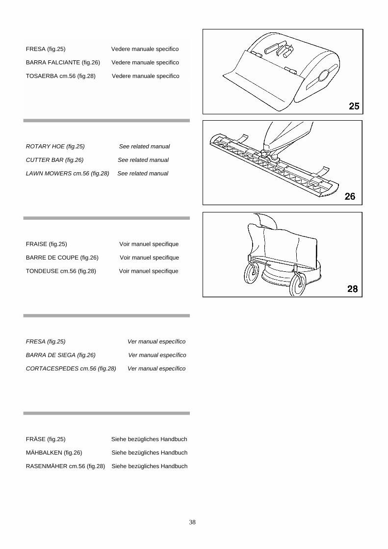
38
FRESA (fig.25) Vedere manuale specifico
BARRA FALCIANTE (fig.26) Vedere manuale specifico
TOSAERBA cm.56 (fig.28) Vedere manuale specifico
ROTARY HOE (fig.25) See related manual CUTTER BAR (fig.26) See related manual LAWN MOWERS cm.56 (fig.28) See related manual
FRAISE (fig.25) Voir manuel specifique
BARRE DE COUPE (fig.26) Voir manuel specifique
TONDEUSE cm.56 (fig.28) Voir manuel specifique
FRESA (fig.25) Ver manual específico
BARRA DE SIEGA (fig.26) Ver manual específico
CORTACESPEDES cm.56 (fig.28) Ver manual específico
FRÄSE (fig.25) Siehe bezügliches Handbuch
MÄHBALKEN (fig.26) Siehe bezügliches Handbuch
RASENMÄHER cm.56 (fig.28) Siehe bezügliches Handbuch
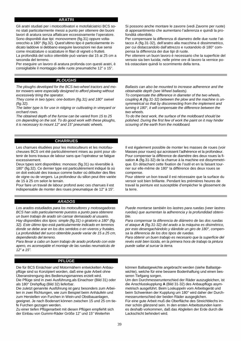
39
ARATRIGli aratri studiati per i motocoltivatori e motofalciatrici BCS so-no stati particolarmente messi a punto per ottenere dei buonilavori di aratura senza affaticare eccessivamente l’operatore.Sono disponibili due tipi: monovomere (fig.31) oppure volta-orecchio a 180° (fig.32). Quest’ultimo tipo è particolarmente in-dicato laddove si debbano eseguire lavorazioni nei due sensicome rincalzature o scalzature in filari di vigneti o frutteti.La profondità del solco ottenibile può variare dai 15 ai 25 cm aseconda del terreno.Per eseguire un lavoro di aratura profonda con questi aratri, èconsigliabile il montaggio delle ruote pneumatiche 12” o 15”.
Si possono anche montare le zavorre (vedi Zavorre per ruote)di appesantimento che aumentano l’aderenza e quindi la pro-fondità ottenibile.Per compensare la differenza di diametro delle due ruote l’at-tacco A (fig.31-32), dell’aratro alla macchina è dissimmetrico,per cui distaccandolo dall’attrezzo e ruotandolo di 180° com-pensa la differenza dei due tipi di ruote.Per ottenere un buon lavoro è necessario che la superficie delversoio sia ben lucida; nelle prime ore di lavoro la vernice po-trà ostacolare quindi lo scorrimento della terra.
PLOUGHSThe ploughs developed for the BCS two-wheel tractors and mo-tor mowers were especially designed to afford plowing withoutexcessively tiring the operator.They come in two types: one-bottom (fig.31) and 180° swivel(fig.32).The latter type is for use in ridging or cultivating in vineyard ororchard rows.The obtained depth of the furrow can be varied from 15 to 25cm depending on the soil. To do good work with these ploughs,it is necessary to mount 12” and 15” pneumatic wheels.
Ballasts can also be mounted to increase adherence and theobtainable depth (see Wheel ballasts).To compensate the difference in diameter of the two wheels,coupling A (fig.31-32) between the plow and the machine is un-symmetrical so that by disconnecting from the implement andturning it 180°, it will compensate the difference between thetwo wheels.To do the best work, the surface of the moldboard should bepolished. During the first few of work the paint on it may hinderscouring of the earth from the moldboard.
CHARRUESLes charrues étudiées pour les motoculteurs et les motofau-cheuses BCS ont été particuliérement mises au point pour ob-tenir de bons travaux de labour sans que l’opérateur se fatigueexcessivement.Deux types sont disponibles: monosoc (fig.31) ou réversible à180° (fig.32). Ce dernier type est particuliérement indiqué là oùon doit exécuté des travaux comme butter où débutter des filesde vigne ou de vergers. La profondeur du sillon peut être variéede 15 à 25 cm selon le terrain.Pour faire un travail de labour profond avec ces charrues il estindispensable de monter des roues pneumatique de 12” à 15”.
Il est également possible de monter les masses de roues (voirMasses pour roues) qui acroissent l’adhérence et la profondeur. Pour compenser la différence de diamètre des deux roues la fi-xation A (fig.31-32) de la charrue à la machine est dissymmetri-que. En détachant cette fixation de l’outil et en la faisant tour-ner sur elle-même de 180° la différence des deux roues secompense. Pour obtenir un bon travail il est nécessaire que la surface duversoir soit bien brillante. Pendant les prémières heures detravail la peinture est susceptible d’empècher le glissement dela terre.
ARADOSLos arados estudiados para los motocultores y motosegadorasBCS han sido particularmente puestos a punto para obtenereun buen trabajo de arado sin cansar demasiado al usuario.Hay disponibles dos tipos: simple (fig.31) o giratorio a 180° (fig.32). Este último tipo está particularmente indicado en terrenosdonde se debe arar en los dos sentidos o en viveros y frutales.La profundidad del surco obtenible puede variar de 15 a 25 cm,dependiendo del terreno.Para llevar a cabo un buen trabajo de arado profundo con esteapero, es aconsejable el montaje de las ruedas neumaticás de12” a 15”.
Puede montarse también los lastres para ruedas (veer lastresruedas) que aumentan la adherencia y la profundidad obteni-ble.Para compensar la diferencia de diámetro de las dos ruedasel ataque A (fig.31-32) del arado a la máquina es disimétrico,por esto desengachándolo y dándole un giro de 180°, compen-sa la diferencia de los dos tipos de ruedas.Para obtenir un buen trabajo es necesario que la superficie delrevés esté bien lúcida, en la primera hora de trabajo la pinturapuede saltar al surcar la tierra.
PFLÜGEDie für BCS Einächser und Motormähern entwickelten Anbau-pflüge sind so Konzipiert worden, daß eine gute Arbeit ohneÜberanstrengung des Bedienungsmannes erzielt wird.Die Pflüge sind in zwei Ausführung,als Einachser (Bild 31) oderals 180° Drehpflug (Bild 32) lieferbar.Die zuletzt genannte Ausführung ist ganz besonders zum Arbei-ten in zwei Richtungen, wie zum Beispiel beim Anhäufeln undzum Herstellen von Furchen in Wein-und Obstbauanlagen,geeignet. Je nach Bodenart können zwischen 15 und 25 cm tie-fe Furchen gezogen werden.Zu einer tiefen Pflügenarbeit mit diesen Pflügen empfiehlt sichder Einbau von Gummi-Räder Größe 12” und 15” Weiterhin
können Ballastgewichte angebracht werden (siehe Ballastge-wichte), welche für eine bessere Bodenhaftung und einen bes-seren Tiefgang sorgen. Um den Durchmesserunterschied der Räder auszugleichen, istdie Anschlusskupplung A (Bild 31-32) des Anbaupflügs asym-metrisch ausgeführt. Beim Loskuppeln vom Arbeitsgerät undbeim Schwenken der Kupplung um 180° wird daher der Durch-messerunterschied der beiden Räder ausgeglichen. Für eine gute Arbeit muß die Oberfläche des Streichblechs im-mer schön glänzend sein. In den ersten Arbeitsstunden kannes deshalb vorkommen, daß das Abgleiten der Erde durch dieLackschicht behindert wird.
ASSOLCATORE RETROFRESA
RIDGER ADAPTABLE BEHIND ROTARY HOE
BUTTOIR MONTE DERRIERE LA FRAISE Pendant le travail garder toujours le fil du versoir vertical en ré- glant l’inclinaison de la charrue de façon à obtenir une coupure nette du terrain. Pour régler la profondeur du labour actionner le petit levier M (fig.31-32) qui fait varier l’incidence de la charrue par rapport au terrain: en le faisant tourner dans le sens des aiguilles d’une montre on obtiendra une augmentation de profon- deur. Au contraire dans l’autre sens une diminution. L’inclinaison de la charrue se règle en actionnant le levier L de commande du verrou de bloquage.
SURCADOR RETROFRESA
Während der Pflügarbeit muß die Kante des Ssenkrecht stehen wobei der Pflüg derart schrämuß, daß ein sauberes Durchschneiden des Für die Einstellung der Arbeitstiefe dient der v(Bild 31-32), mit welchem die Einschnittiefe dden eingestellt werden kann. Eine Drehung imgibt eine größere Tiefe, eine Drehung entgegsinn eine kleinere Tiefe beim Pflügen. Die Nekann dagegen durch Betätigen des Hebels L der auf die Verriegelung entwirkt.
31-32) 33).
31-32)
33).
33).
3
1-32)40
FURCHENZIEHER HINTER DER FRÄSEtreichblechs immerg gestellt werden
Bodens erzielt wird.ordere Handgriff Mes Plugs in den Bo- Uhrzeigersinn er-
en dem Uhrzeiger-igung des Pflügsgeregelt werden,
Er macht Sä- und Bewässerungfurchen und er wird hinter der Frä-se montiert, ohne die Haube zu beseitigen. Die Furchentiefe wirddurch das Heben (höhere Tiefe) oder das Senken des Schlittens Beingestellt.Die Breite wird durch Änderung der Flügel mit den Zugstangen C(Bild 33) eingestellt.
33).

41

42
ASSOLCATORE REGISTRABILE
L’assolcatore registrabile (fig.35) è un attrezzo particolarmentestudiato per eseguire solchi di semina o d’irrigazione. Si applicacome gli aratri e la fresa, sulla flangia attrezzi situata nella parteposteriore della scatola cambio.La possibilità di variare la posizione delle due ali B permette laregolazione della larghezza del solco da un minimo di 10 ad unmassimo di 30 cm.La profondità ottenibile può variare da 10 a 20 cm. La variazionedi incidenza si ottiene agendo sui tiranti di regolazione C.
Nel caso si debba operare in terreni particolarmente duri è oppor-tuno eseguire prima un’operazione di fresatura e quindi procede-re al lavoro con l’assolcatore. Le prestazioni ottenibili possono es-sere aumentate montando le ruote pneumatiche da 12” o 15”.
ADJUSTABLE RIDGER The adjustable ridger (fig.35) is an implement specially designedfor making furrows for seeding or irrigation. It is attached likeploughs and rotary hoe to the implement coupling flange locatedin the back of the gearbox.
BUTTOIR A AILES REGLABLES
Le butteur à ailes réglables (fig.35) est un outil étudié particulière-ment pour exécuter des sillons d’ensemencement ou d’irrigation.On l’applique comme les charrues et la fraise pour la bride atta-che outils située sur la partie postérieure de la boîte de change-ment de vitesses. La possibilité de changer la position des deuxailes B permet le réglage de la largeur du sillon d’un minimum de10 cm à un maximum de 30 cm.La profondeur que on peut obtenir varie de 10 à 20 cm. Le chan-gement d’incidence est obtenue en agissant sue les tirants de ré-glage C.
SURCADOR REGISTRABLE
El surcador registrable (fig.35) es un apero particularmente estu-diado para hacer surcos en sembrados y zonas de riego. Semonta igual que el arado y la fresa, sobre la arandela de ataquede aperos situada en la parte superior de la caja de cambio. Laposibilidad de variar la posición de las dos alas B, permite la re-gulación de la largura del surco de 10 a 30 cm.
VERSTELLBARER FURCHENZIEHER
Der verstellbare Furchenzieher (fig.35) ist speziell für das Ziehenvon Saatbett-oder Bewässerungsfurchen entwickelt worden.Er wird genau wie die Anbaupflüge uns das Fräswerk am Geräte-kupplungsflansch hinten am Getriebekasten befestigt.Die beiden Streichbleche B sind verstellbar angeordnet, so daßbeliebig breite Furchen zwischen 10 und maximal 30 cm gezogenwerden können.Die Arbeitstiefe kann zwischen 10 und 20 cm variieren. Der Nach-lauf wird durch Betätigung der Zugstangen C verstellt.
Wenn auf besonders harten Böden gearbeitet werden muß,empfiehlt es sich, vor dem Furchenziehen den Boden zunächst mitdem Fräswerk zu lockern. Die Leistung dieses Arbeitsgeräts kannweiter erhöht werden, wenn man Gummi-Räder Größe 12” und 15”verwendet.

43
CARRELLO DI TRASFERIMENTO(non omologato su strada)
CARRELLO DI LAVORO(non omologato su strada)
Il carrello di trasferimento (fig.36) si può agganciare alla mac-china senza togliere la fresa, girando l’asta coltello A. Il carrel-lo di trasferimento si aggancia alla macchina montando l’at-tacco curvo C.
La macchina deve essere dotata di freni.
MANUTENZIONE: ingrassare periodicamente le boccole del-le ruote, smontando le ruote stesse e riempiendo di grasso lacamera tra le due boccole.
Questo carrello è utilizzabile solamente con: barre falcianti etosaerba a due lame con cestello di raccolta. La macchinadeve essere dotata di freni. Si fissa alla macchina montandoi due attacchi A all’esterno delle ruote, agganciando i bracci aforcella F sulle boccole B e fissandoli posizionando le spine ascatto C (fig.37).
MANUTENZIONE: ingrassare periodicamente le boccole del-le ruote, smontando le ruote stesse e riempiendo di grasso lacamera tra le due boccole.
MOVING SULKY WORKING SULKY
It can be mounted (fig.36) to the machine without removingthe rotary hoe, by turning the knive rod A. The moving sulky ismounted to the machine by fitting curved coupling C.
The machine must be equipped with brakes.
MAINTENANCE: periodically grease the wheel bushes by re-moving the wheels and filling with grease the space betweenthe two bushes.
This sulky can be used only with cutter bars and 2-blades lawnmower with grass bag. The machine must be equipped withbrakes.It is mounted to the machine by fitting the two couplings A out-side the wheels, hooking fork tubes F on bushes B and lockingthem by spring pins C (fig.37).
MAINTENANCE: periodically grease the wheel bushes,remo-ving the wheels and filling with grease the space between thetwo bushes.
SULKY DE DEPLACEMENT SULKY DE TRAVAILLe sulky de déplacement (fig.36) peut être monté sur la ma-chine sans ôter la fraise, en tournant la tige du couteau A.Celui est monté à la machine à l’aide de l’attache courbe C.
La machine doit être équipée de freins.
ENTRETIEN: graisser périodiquement les cages des rouesen démontant les roues et en remplissant de graisse ladistance entres les douilles.
Ce sulky peut être utilisé seulement avec les barres de coupeet la tondeuse à deux lames avec bac. La machine doit êtreéquipée de freins. Il s’attache à la machine en montant lesdeux attaches A à l’extérieur des roues, en accrochant les four-chettes F sur les douilles B et en les fixant avec les épingles àressort C (fig.37). ENTRETIEN: graisser périodiquement les cages des roues endémontant les roues et en remplissant de graisse la distanceentres les cages.
CARRO DE TRANSPORTE CARRO DE TRABAJOEl carro de transporte (fig.36) se puede enganchar a la má-quina sin sacar la fresa, girando el asta del cuchillo A. Elcarro de transporte se engancha a la máquina montando elataque curvo C.
La máquina tiene que estar dotada de frenos.
MANUTENCÍON: Engrasar periódicamente los aros de lasruedas, desmontando las ruedas a menudo y llenando degrasa la cámara entre los dos aros.
Este carro, puede utilizarse solo con la barra de siega y corta-césped de dos cuchillas con recogedor. La máquina tieneque estar dotada de frenos. Se fija a la máquina montandolos dos ataques A al exterior de las ruedas, enganchando losbrazos con la horquilla F sobre los aros B y fijándolos posicio-nando las espinas al escape C (fig.37).
MANUTENCÍON: Engrasar periódicamente los aros de lasruedas, desmontando las ruedas a menudo y llenando degrasa la cámara entre los dos aros.
TRANSPORTSITZWAGEN ARBEITSSITZWAGENDer Transportsitzwagen (Bild 36) kann an Maschine montiertwerden, ohne die Fräse abzumontieren. Dazu Messerstift Adrehen. Der Wagen an Maschine mittels gekrümmtem Ansch-luß C montiert.
Die Maschine muß dazu mit Bremsen ausgerüstet sein.
WARTUNG: Die Radlager in regelmässigen Zeitabstanden ein-fetten. Dazu Räder ausbauen und die Fettkammer zwischenden beiden Lagern mit Fett füllen.
Dieser Wagen kann nur zusammen mit Mähbalken und 2-Messer Rasenmähern mit Grasfangkorb gebraucht werden.Die Maschine muß dazu mit Bremsen ausgerüstet sein.Zur Befestigung mit der Maschine die zwei KupplungsstückeA ausserhalb der Räder montieren, Gabel F auf Lager B an-haken und sie mit den Stiften C befestigen (Bild 37). WARTUNG: Die Radlager der Räder in regelmässigen Zeit-abständen einfetten. Dazu Räder ausbauen und die Fettkam-mer zwischen den beiden Lagern mit Fett füllen.
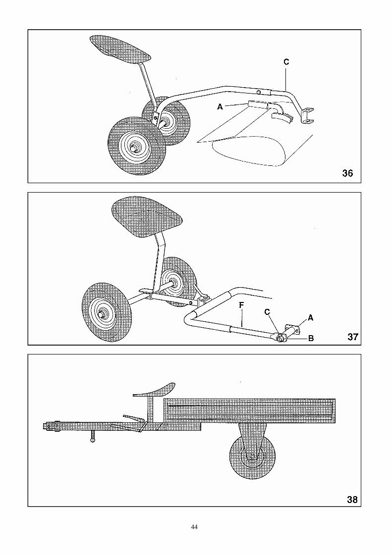
44
45
RIMORCHIO A RUOTE LIBERE(non omologato su strada)
Il rimorchio a ruote libere (fig.38) é un attrezzo molto utile pereseguire piccoli trasporti aziendali. La sua maneggevolezza, ilridotto ingombro e la sua rapida applicazione ne costituisconole caratteristiche più salienti.Il rimorchio si può applicare direttamente alla macchina ag-ganciandolo con l’apposito attacco curvo C (fig.36), lasciandoapplicata la fresa.Le ruote motrici sono quelle anteriori, ossia, quelle della mac-china; la guida viene effettuata a mezzo del manubrio; le ruo-te posteriori sono folli e montate su cuscinetti a sfere.
La frenatura è assicurata da due freni a tamburo montati nelleruote posteriori e comandati da un pedale posto sul timonedel rimorchio. Il freno di stazionamento è comandato da unaleva a mano e agisce sugli stessi freni delle ruote posteriori.
La portata utile del rimorchio è di 400 kg; le dimensioni delcassone sono: 1,50 m x 1,10.
TRAILER WITH FREE WHEELS
The trailer with free wheels (fig.38) is a very useful accessoryfor light hauling around the farm. Its most outstanding featuresare its ease of handling, small size and easy attachment.The trailer can be applied directly to the machine leaving therotary hoe in place and connecting it to curved coupling C(fig.36).The driving wheels are the front ones, i.e. those of the machi-ne which is steered by the handlebar.The rear wheels are idle and mounted on ball bearings.
There are two drum brakes mounted in the back wheels andcontrolled by a pedal located on the trailer shaft. The parking-brake is controlled by a hand lever and acts on the backwheels.Useful capacity of the trailer is 400 kg. Box dimensions are1,50 m x 1,10.
REMORQUE A ROUES LIBRES
La remorque à roues libres (fig.38) est un accessoires très uti-le pour de petits transports d’entreprise. Sa maniabilité, le peude place qu’elle occupe et sa rapidité d’application en costi-tuent les caractéristiques essentielles.La remorque peut être appliquée directement a la machine enlaissant la fraise et en la joignant à l’attache courbe C (fig.36).Les roues motrices sont les roues antérieurs, c’est-à-dire cel-les de la machine; la direction est donnée par le mancheron;les roues postérieures tournent à vide et sont montées surroulement.
Le freinage se fait par deux freins à tambour montés dans lesroues postérieures et commandés par une pédale située surle timon de la remorque. Le frein de stactionnement est actionné par un levier à mainet agit directement sur les freins des roues postérieures. La portée utile de la remorque est de 400 kg; les dimensionsdu caisson sont de 1,50 m x 1,10.
REMOLQUE DE ARRASTREEl remolque (fig.38) de arrastre es un apero muy útil para ha-cer pequeños transportes dentro de la finca. Su maniobrabili-dad, sus reducidas dimensiones y su rápida aplicación costi-tuyen sus principales características.El remolque se puede aplicar directamente a la máquina en-ganchándolo con el ataque curvo C (fig.36), dejando montadala fresa.Las ruedas motrices son las anteriores, es dicir, las de la má-quina; la guía se efectúa mediante el manillar; las ruedas po-steriores son libres y montadas sobre cojinetes de esfera.
El frenado viene asegurado por los dos frenos de tambor mon-tados en las ruedas posteriores y comandados por un pedalsituado en el timón del remolque.El freno de estacionamiento está comandado por una palancade mano que actúa sobre los mismos frenos de las ruedas po-steriores.La carga útil del remolque es de 400 kg; las dimensiones dela caja son 1,50 m x 1,10.
ANHANGER MIT FREILAUFRADERNDer Anhänger (Bild 38) ist für kleinere Transportauftgaben imRahmen des Betriebs gedacht. Handlichkeit, geringer Platz-bedarf und schnelles Ankuppeln an den Einachser: das sindseine hervorstehendsten Charakteristiken.Der Anhänger wird direkt an den Maschine angehängt,mittels-des gekrummten Anschlusses C ohne Demontage der Fräse(Bild 36). Die Räder des Maschine sind dann die Antriebsräder.Die Len-kung erfolgt mittels der Holmen des Maschinen. Die Hinterrä-der, auf Kugellagern montiert, laufen mit.
Zum Abbremsen dienen zwei Trommelbremsen an den Hinter-rädern, die durch ein an der Dreichsel des Anhangers ange-ordnetes Bremspedal betatigt werden. Die Handbremse wird mit einem Handhebel betätigt, der wiederum auf dei beiden Hinterradbremsen einwirkt. Die Anhangernutzlast beträgt 400 kg. Abmessungen der La-deflache: 1,50 x 1,10 m.

46
RUOTE PNEUMATICHESono particolarmente indicate per gli impieghi agricoli in quan-to il profilo artigliato consente sempre una buona aderenzadella macchina a terra sia sui terreni duri che soffici.
Le ruote 4.0-10, 5.0-10, 6.5/80-12, e 6.5/80-15 hanno il cer-chio a carreggiata variabile che permette di avere 2 possibilitàdi montaggio con carreggiate diverse (fig.40).
Per lavorare con aratri od assolcatori è consigliabile l'applica-zione di ruote con diametro superiore, questo per incrementa-re notevolmente l'aderenza e lo sforzo di traino.
Con queste ruote si possono applicare anche gli altri attrezzi:tosaerba, barra, ecc. montando sulla presa di forza del cambiouna prolunga o attacco rapido, per evitare l'interferenza tra leruote e gli attrezzi stessi.
PNEUMATIC WHEELS They are particularly suitable for agricultural uses since theclaw tread always provides good adherence of the machine tothe ground, either on hard or soft grounds. The wheels 4.0-10, 5.0-10, 6.5/80-12 and 6.5/80-15 have therim with adjustable track, which offers two assembling possibi-lities with different tracks (fig.40). When working with ploughs and ridgers it is advisable to mountwheels with a larger diameter. Their larger diameter and theirclaw tread increase the adherence to the ground and theirtraction.
These wheels can be fitted also with the other implements:lawn mower, bars, etc., by fitting on the gearbox P.T.O. theimplement extension or quick hitch, in order to avoid interfe-rences between the wheels and the implements.
ROUES PNEUMATIQUESElles sont particulièrement indiquées pour les usage agrico-les, puisque le profil dentelé permet toujours une bonne adhé-rence de la machine au terrain, qu'il s'agisse de terrains dursou meubles.
Les roues 4.0-10, 5.0-10, 6.5/80-12, et 6.5/80-15 ont la janteà chaussée variable qui permet d'avoir deux possibilités demontage avec des chaussées différentes (fig.40).Pour travailler avec les charrues et les buttoirs on conseille demonter des roues avec un diamètre supérieur pour augmenterconsidérablement l'adhérence et la force de traction.
Avec ces roues on peut appliquer aussi les autres accessoires:tondeuse, barre, etc., en montant sur la prise de force de laboite de vitesses une rallonge ou une attache rapide, pouréviter des interférences entre les roues et les outils.
RUEDAS NEUMATICASSon particularmente indicadas para maquinaria agricola yaque el perfil garrudo ofrece siempre una buena adherencia dela máquina al suelo, ya sea sobre terrenos duros o blandos.
Las ruedas 4.0-10, 5.0-10, 6.5/80-12 y 6.5/80-15 tienen lallanta con paso variable que les permite tener 2 posibilidadesde montaje con pasos distintos (fig.40).Para trabajar con arados o surcadores es aconsejable la apli-cación de ruedas con diámetro superior, esto se hace para in-crementar notablemente la adherencia y el esfuerzo de arrastre.
Con estas ruedas pueden aplicarse también otros aperos:cortacésped, barra, etc., montando sobre la toma de fuerzadel cambio una prolungación o enganche rápido, para evitarla interferencia entre las ruedas y los aperos mencionados.
GUMMI-RÄDERSie sind für landwirtschaftliche Einsätze besonders geeignet,weil ihr Klauenprofil eine gute Haftung der Maschine auf har-ten oder weichen Boden erlaubt.
Die Räder 4.0-10, 5.0-10, 6.5/80-12, und 6.5/80-15 haben Fel-gen mit verstellbarer Spurweite, was zwei Montagemöglichkei-ten mit zwei verschiedenen Spurweiten ermöglichst (Bild 40).Um mit Pflügen oder Furchenziehern zu arbeiten, werden grö-ßere Räder empfohlen. Der Durchmesser erhöht die Haftungam Boden sowie die Zugkraft.
Mit diesen Gummi-Rädern können auch andere Arbeitsgeräte,wie Mähbalken, Rasenmähern, u.s.w. angebaut werden, indemauf die Zapfwelle die Verlängerung für Arbeitsgeräte montiertwird. Die Verlängerung dient dazu, Interferenzen zwischenden Rädern und denselben Arbeitsgeräten zu vermeiden.

47
RUOTE “SUPER-BITE” (antideriva)Queste ruote sono particolarmente indicate per falciare su ter-reni in pendenza.Accoppiate alle ruote pneumatiche incrementano sia la trazio-ne che la stabilità laterale della macchina (fig.41).
WHEELS “SUPER-BITE” (Antidrift)Those wheels are particularly recommended to mow on slo-ping ground. Coupled to pneumatic wheels they increase both the tractionand lateral stability of the machine (fig.41).
ROUES “SUPER-BITE” (Antidérive)Ces roues sont particulièrement indiquées pour faucher surterrains en pente.Unies aux roues pneumatiques elles augmentent la traction etla stabilité latérale de la machine (fig.41).
RUEDAS “SUPER-BITE” (Antideriva)Estas ruedas son particularmente indicadas para falcar sobreterrenos en pendencia.Acopiada a las ruedas pneumáticas incrementan sea la trac-ción que la estabilidad lateral de la máquina (fig.41).
RADER “SUPER-BITE” (Rutschfest)Diese Räder bieten besonders auf geneigtem Undergrund aus-gezeichnete Bodenhaaftung.Gekoppelt mit den pneumatischen Reifen verbessert sich so-woohl die traltion als auch die Lateralstabilitat des Fahrzeugs(Bild 41).
48
RUOTE METALLICHE A GABBIA
Queste ruote sono disponibili in tre misure diverse: con diame-tro da 43, 49 e 58 cm. (vedi tab.1).
ANELLI DI GEMELLAGGIO
Queste ruote trovano particolare utilizzazione nell'impiego delmotocoltivatore con fresa in terreni molto duri.Infatti le traversine poste sulla circonferenza delle ruote pene-trano nel terreno realizzando quindi un buon ancoraggio dellamacchina a terra e impedendo alle ruote di slittare.L'uso delle ruote a gabbia è conveniente se limitato a questicasi. Negli altri casi in genere è consigliabile l'uso delle ruotepneumatiche,che, dove non siano richieste prestazioni di ade-renza limite, danno alla macchina una trazione più regolare efanno da cuscinetto elastico tra questa e la terra.
Questi anelli, accoppiati alle ruote a gabbia con diametro da49 cm, ne raddoppiano la larghezza ed aumentano quindi no-tevolmente l’aderenza. Sono particolarmente indicati per lafresatura in terreni molto duri e compatti (fig.43).
STEEL CAGE WHEELS
These wheels are available in 3 different sizes: diameter 43,49 and 58 cm. (see tab.1).
TWINNING RINGS
These wheels are specially designed to be used with the two-wheel tractor mounting the rotary hoe on hard ground. The crosspieces on the wheels perimeter penetrate theground, and assure good griping of the machine to the earth,and prevent slippage. Cage wheels are profitable to use only in these conditions.Otherwise it is better to use pneumatic wheels which, if thereis no severe problem of adherence, give the machine asteadier traction and form a flexible buffer between it and theground.
These rings, coupled to the cage wheels diam. 49, double theirwidth and increase therefore remarkably their adherence. Theyare particularly suitable to hoe very hard and compact soils(fig.43).
ROUES METALLIQUES
Les roues sont disponibles dans 3 dimensions différentes:diam. 43, 49 et 58 cm. (voir tab.1).
BAGUES D’ACCOUPLEMENT
Ces roues sont surtout employées pour l'utilisation du motocul-teur avec fraise sur terrains très durs. En effet, les traverses po-sées sur la circonférence des roues pénètrent dans le terraincréant ainsi un bon ancrage de la machine à la terre en empê-chant ainsi aux roues de glisser.L'utilisation des roues métalli-ques d'adhérence est utile si ellese limite aux cas ci-dessus. Pour tous les autres cas en généralil est préférable d'utiliser des roues pneumatiques qui donnentà la machine, lorsqu'on ne lui demande pas de prestations deforte adhérence, une traction plus régulière en formant un cous-sin élastique entre le terrain et la machine.
Ces bagues, accouplées aux roues métalliques de diam. 49 enredoublent la largeur et par conséquent augmentent l’adhéren-ce. Elles sont particulièrement adéquates pour fraiser des ter-rains très durs et compacts (fig.43)
RUEDAS DE JAULA
Estas ruedas se fabrican en 3 medidas distintas: de 43, 49 y58 cm de diámetro (veer tab.1).
ANILLOS GEMELOS
Estas ruedas están particularmente indicadas para trabajarcon el motocultor con fresa en terrenos muy duros.En efecto, los traveseros situados en la circunferéncia de lasruedas, penetran en la tierra realizando un buen anclaje de lamáquina al suelo e impidiendo que las ruedas patinen.El uso de las ruedas de jaula se limita a este caso. En otroscasos es aconsejable el uso de ruedas neumáticas que, aun-que no tengan prestaciones de adherencia máxima, dan a lamáquina una tracción más regular y hacen de cojinete elásti-co entre la máquina y el suelo.
Estos anillos, acoplables a las ruedas de jaula con diámetrode 49 cm, doblan la largura y aumentan así notablemente laadherencia. Estan particularmente indicados para la fresadu-ra en terrenos muy duros y compactos (fig.43).
METALLSTOLLENRADER
Diese Räder sind in 3 verschiedenen Abmessungen lieferbarØ 43, 49 und 58 cm (siehe Tafel 1).
ZWILLINGSRINGE
Die Gitterräder werden vorzugsweise beim Fräsen auf sehrhartem Boden eingesetzt. Die Querstege der Gitterräder drin-gen in den Boden ein und gewährleisten damit eine gute Ver-ankehrung der Maschine ohne, daß es zum Durchrutschender Räder kommt. Der Einsatz der Gitterräder ist nur in dengeschilderten Verhältnissen günstig.In allen anderen Fällen ist im allgemeinen das Arbeiten mitLuftreifen gunstiger, weil sie eine bessereZugkraftubertragung gewahrleisten und ein federndes Kissenzwischen der Maschine um dem Erdboden bilden.
Diese Ringe, die mit den Stollenrädern Ø 49 verbunden sind,verdoppeln deren Breite und erhöhen deshalb derenBodenhaftung in bemerkenswerter Weise.Sie sind besonder angezeigt, um sehr harte und kompakteBöden zu Fräsen (Bild 43).

49
GEMELLAGGIO RUOTE
Si possono gemellare le ruote 4.00-8 e le 4.0-10 interponendodue distanziali D da 6 cm (fig.45) fra una ruota e l’altra (vediDistanziali ruote).
WHEELS TWINNING You can twin the wheels 4.00-8 and 4.0-10 installing two 6 cmspacers D (fig.45) between the two wheels (see Wheel spa-cers).
JUMELAGE ROUES
On peut jumeler les roues 4.00-8 et 4.0-10 en montant deuxmoyeux D de 6 cm (fig.45) entre une roue et l’autre (voirMoyeux pour roues).
RUEDAS GEMELAS
Pueden duplicarse las ruedas 4.00-8 y las 4.0-10 interponien-do dos distanciales D da 6 cms. (fig.45) entre una rueda y laotra (veer Distanciales ruedas).
ZWILLINGSBEREIFUNG
Die Zwillingsbereifung der Räder 4.00-8 und 4.0-10 erfolgtdurch zwei Distanzstücke D 6 cm (Bild 45) zwischen den Rä-dern (siehe Distanzstücke für Räder).

50
DISTANZIALI PER RUOTE
Servono per allargare la carreggiata e aumentano quindi lastabilità della macchina sulle pendenze trasversali. Si mon-tano interposti tra le ruote e i mozzi portaruote e allarganola carreggiata di 6 cm per parte (fig.46).
WHEEL SPACERS These spacers are used to widen the track and thus increasethe stability of the machine on sloping ground. They aremounted between the wheels and the hubs and widen thetrack by 6 cm on each side (fig.46).
ENTRETOISES POUR ROUES
Leur utilisation a pour but d’élargir la voie en augmentant parconséquent la stabilité de la machine sur les pentes transver-sales. Elles se situent entre les roues et les moyeux et élar-gissent la voie de 6 cm de chaque côté (fig.46).
DISTANCIALES PARA RUEDAS
Sirven para aumentar la anchura y a mejorar así la estabili-dad de la máquina en disniveles transversales. Se montaninterpuestas entre las ruedas y los tapabucos de las ruedas,aumentando 6 cms por lado la anchura (fig.46).
SPURVERSTELLELEMENTE
Mit diesen Distanzstücken kann die Spurweite vergrössert wer-den so, daß die Stabilität des Einachsers bei Hanglagen erhöhtwird. Die Verstellelemente werden zwischen die Räder und dieRadnaben eingebaut und ergeben auf jeder Seite eine Spur-weitenvergrößerung von 6 cm (Bild 46).

51
ZAVORRE PER RUOTE
Queste zavorre servono per appesantire la macchina ed ave-re quindi una trazione superiore. Si possono impiegare nei la-vori di aratura ed assolcatura. Si fissano ai mozzi ruote condue dei quattro dadi che fissano le ruote (fig.48).
Vedi Tab. riassuntiva n°1.
BALLASTS FOR WHEELS These ballasts are used to make the machine heavier and tohave therefore a higher tractive force. They can be used inploughing or ridging works. They must be fixed to the wheelhubs with two of the four nuts fastening the wheels (fig.48). See table n°1.
LEST POUR ROUES
Ces masses servent pour alourdir la machine et avoir donc uneffort de traction supérieur. On peut les employer dans lestravaux de charruage ou sillonnage. Ces-ci doivent être fixésaux moyeux des roues au moyen de deux des quatre écrousqui fixent les roues (fig.48).
Voir table 1.
LASTRES PARA RUEDAS
Estos lastres sirven para hacer más pesada la máquina y te-ner así un esfuerzo de tracción superior. Pueden utilizarseentrabajos con el arado y el surcador. Se fijan a los tapabu-cos de las ruedas con dos de las cuatro tuercas que fijan larueda (fig.48).
Ver tabla 1.
BALLASTGEWICHTE FUR RADER
Die Ballastgewicht dienen dazu, die Maschine schwerer zu ma-chen, um eine höhere Zugkraft zu erwirken. Sie können beiPflug oder Furchenzieharbeiten verwendet werden. Sie werdenan den Räder mit zwei der vier Mutter die Räder fixieren, fest-gestellt (Bild 48).
Siehe Übersichtstabelle 1.
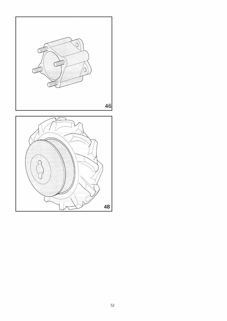
52
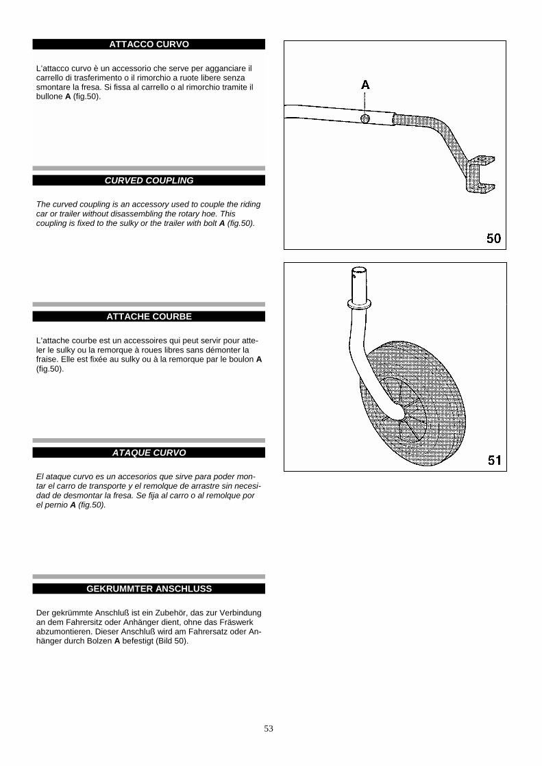
53
ATTACCO CURVO
L’attacco curvo è un accessorio che serve per agganciare ilcarrello di trasferimento o il rimorchio a ruote libere senzasmontare la fresa. Si fissa al carrello o al rimorchio tramite ilbullone A (fig.50).
CURVED COUPLING
The curved coupling is an accessory used to couple the ridingcar or trailer without disassembling the rotary hoe. Thiscoupling is fixed to the sulky or the trailer with bolt A (fig.50).
ATTACHE COURBE
L’attache courbe est un accessoires qui peut servir pour atte-ler le sulky ou la remorque à roues libres sans démonter lafraise. Elle est fixée au sulky ou à la remorque par le boulon A(fig.50).
ATAQUE CURVO
El ataque curvo es un accesorios que sirve para poder mon-tar el carro de transporte y el remolque de arrastre sin necesi-dad de desmontar la fresa. Se fija al carro o al remolque porel pernio A (fig.50).
GEKRUMMTER ANSCHLUSS
Der gekrümmte Anschluß ist ein Zubehör, das zur Verbindungan dem Fahrersitz oder Anhänger dient, ohne das Fräswerkabzumontieren. Dieser Anschluß wird am Fahrersatz oder An-hänger durch Bolzen A befestigt (Bild 50).

54
RUOTINO SOSTEGNO FRESA
E’ molto utile nei trasferimenti della macchina perché tenendosollevata la fresa dal terreno ne rende più agevole e menofaticosa la traslazione (fig.51).
ROTARY HOE WHEEL
This wheel is very useful when moving the machine on longdistance because it holds the hoe up off the ground and ma-kes travelling easier (fig.51).
ROUE PORTEUSE POUR FRAISE
Elle est particulièrement utile au cours des déplacements dela machine car en gardant soulevée la fraise du sol elle rendle déplacement plus aisé et moins fatigant (fig.51).
RUEDA SOPORTE FRESA
Es muy útil en el transporte de la máquina porque teniendolevantada la fresa del suelo es más fácil o al menos, menoscansado el traslado (fig.51).
LAUFRAUD FUR FRASABSTUTZUNG
Das Laufrad dient für die Transportfähren der Maschine. Esstützt die Fräse über dem Böden ab und erleichert damit denTransport von einem Platz zum anderen (Bild 51).

55
PROTEZIONE ANTERIORE PER BARRA PROTEZIONI LATERALI PER BARRA
É obbligatorio applicare la protezione anteriore ogni volta che si effettua un trasferimento o qualora la barra riman- ga esposta al pubblico o ferma in deposito (fig.54).
Servono per impedire che la lama, uscendo nella sua corsa dilavoro dall’ingombro della barra, danneggi le piante vicine o sidanneggi urtando contro ostacoli o sassi. Vanno montate alleestremità della barra: per la barra Europa la protezione A(fig.55), per le barre fitte e semifitte la protezione B (fig.56).
Servono anche come protezioni antinfortunistiche.
CUTTER BAR FRONT PROTECTIONS CUTTER BAR SIDE PROTECTIONS It is recommended to apply the front protection each time a transfer is performed or whenever the bar remains ex- posed or in the deposit (fig.54).
Their purpose is to avoid that the blade, when it comes out fromthe bar seat during its running, damages itself or the near plantsknocking against obstacles or stones. They must be fitted at theends of the cutter bar; for the EUROPE cutter bar, fit protectionA (fig.55), for the cutter bars with low cut or middle cut finger fitprotection B (fig.56).
They can also be used as accident prevention tools.
PROTECTION AVANT POUR BARRE PROTECTIONS LATERALES POUR BARRE
Il est obligatoire d’appliquer la protection antérieure cha- que fois que l’on transfère la machine ou lorsque la barre reste exposée au public ou garée dans une remise (fig.54).
Leur but est d’éviter que la lame, en sortant du siège de la bar-re pendant le travail, endommage les plantes proches ou s’en-dommage en heurtant des obstacles ou des pierres.Ces protections doivent être montées aux extrémités de la bar-re; pour la barre EUROPE protection A (fig.55), pour les barresavec dents à coupe courte ou à coupe moyenne protection B(fig.56).
Ils sertent aussi pour protection anti-infortunistique.
PROTECCION ANTERIOR PARA BARRA PROTECCIONES LATERALES PARA BARRA
Es obligatorio aplicar la protección anterior cada vez que usted quiere efectuar un desplazamiento o si la palanca está exhibida o parada en deposito (fig.54).
Sirven para impedir que la cuchilla, usándose la barra normal-mente, no dañe plantas vecinas o se rompa al topar con obstá-culos o piedras. Tienen que ser montadas en la extremidad dela barra; para la barra EUROPA la protección A (fig.55), paralas barras finas, semifinas la protección B (fig.56).
Ellas sirven como protección anti-infotunio, támbien.
FRONTSCHUTZ FUR MAHBALKEN SEITENSCHUTZ FUR MAHBALKEN
Es ist notwendig den Frontschutz anzuwenden in Fall einer Übertragung und jedes Mal der Mähbalken bleibt ausgestellt oder im Lagerplatz (Bild 54).
Vermeidet Beschädigungen am Blatt selbst, wenn es währenddes Arbeitslauf sich löst, sowie beim Anstoß an Hindernisseoder Steine. Dieser Schutz muß an die beiden äußersten En-den des Balkens montiert werden: für den EUROPA Mähbal-ken Schutz Typ A (Bild 55), für die Mähbalken mit Tiefschnitt-oder Mittelschnittzähnen Schutz Typ B (fig.56).
Sie dienen als Schutz gegen Unfälle.

56

57
ATTACCO RAPIDO ATTREZZI
Serve per cambiare rapidamente gli attrezzi sulla macchina.E’ composto da due parti, un cannotto A che si monta allamacchina ed un codolo B che si fissa all’attrezzo.Per montare l’attrezzo alla macchina basta inserire il codolo Bnel cannotto A ed agganciarli abbassando il perno G.Mantenere il codolo B ed il cannotto A lubrificati con grassoper favorire il montaggio e lo smontaggio (fig.58).
QUICK HITCH FOR IMPLEMENTS It allows to change rapidly the implements on the machine. Itis composed by two parts: one tube A which is fitted on themachine and one tang B which is inserted into the tube whenthe implement is fitted. The fastening is made with hook G. Keep tang B and tube A always lubricated with grease to ma-ke assembly and disassembly easier (fig.58).
ENGANCHE RAPIDE OUTILS
Elle sert pour changer rapidement les outils de la machine.Elle est composée par deux pièces: un petit tuyau A qui semonte à la machine et un pivot B qui se fixe à l’outil.Pour monter l’outil de la machine introduire le pivot B dans letuyau A et les accrocher en baissant le pivot G. Maintenir lepivot B et le tuyau A bien lubrifiés avec de la graisse pourpermettre le montage et le démontage (fig.58).
ENGANCHE RAPIDO APEROS
Sirve para cambiar rápidamente los aperos en la máquina.Está compuesto de dos partes, una parte A que se monta a lamáquina y la otra B que se fija al apero.Para montar el apero a la máquina basta inserir la parte B enla parte A y engancharlos bajando el perno G.Mantener la parte B y la parte A lubrificadas con grasa parafacilitar el montaje y el desmontaje (fig.58).
SCHNELLANSCHLUß FUR ARBEITSGERATE
Er dient, um die Arbeitsgeräte der Maschine schnell zu wech-seln. Er ist aus zwei Teilen zusammengesetzt: Buchse A, wel-che auf die Maschine montiert wird und Zwischenstück B,wel-ches auf das Arbeitsgerät befestigt wird.Um das Arbeitsgerät an der Maschine zu montieren, Zwischen-stück B in Buchse A hineinstecken und durch niedriger Stel-lung des Stiftes G anhaken.Zwischenstück B und Buchse A mit Fett gut geschmiert hal-ten, um die Montage und Demontage zu erleichtern (Bild 58).
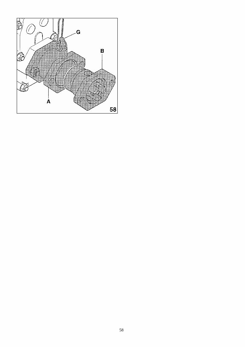
58

59
PRESA DI FORZA UNIFICATA D=35 CATENE DA NEVE
Questa presa di forza, applicata sulla presa di forza standardcome fosse una prolunga attrezzi, porta all’esterno un alberoscanalato di 35 mm di diametro e di dimensioni unificate comele prese di potenza dei trattori, secondo le norme DIN 9611.A questo albero si possono collegare giunti cardanici, puleggee attrezzi vari (fig.59).
Sono costruite in plastica speciale rinforzata con inserti metal-lici.Montate sulle ruote, migliorano nettamente la capacità di lavo-ro dello spazzaneve (fig.60).
STANDARD POWER TAKE-OFF D=35 SNOW CHAINS
This PTO fitted on the machine PTO as an implement exten-sion, takes out a 35 mm splined shaft that is of the same sizeof the tractors PTO, according to DIN standards 9611.By this shaft you can drive universal joint, pulleys and manyother implements (fig.59).
They are made of special plastic, reinforced with metal parts.When they are fitted on wheels, they highly improve the workcapacity of the snow thrower (fig.60).
PRISE DE FORCE UNIFIEE D=35 CHAINES NEIGE
Cette prise de force appliquée sur la prise de force standardcomme une rallonge pour outils, porte à l’extérieur un arbrecannelé de 35 mm de diamètre qui a des dimensions unifiéescomme les prises de puissance des tracteurs, selon les reglesDIN 9611.A cette arbre on peut appliquer des joints cardaniques, poulieset d’autres outils (fig.59).
Elles sont en plastique spéciale renforcée avec des piècesmétalliques. Montées sur les roues elles augmentent beaucoup la capacitéde travail du chasse-neige (fig.60).
TOMA DE FUERZA UNIFICADA D=35 CADENAS PARA NIEVE
Esta toma de fuerza aplicada sobre la toma de fuerza principaldel motocultor como si fuera una extensión de aperos lleva alexterior un eje estriado de 35 mm de diámetro y de dimensio-nes unificadas como las tomas de fuerza de los tractores segúnlas reglas DIN 9611.A este eje se pueden acoplar juntas cardánicas, poleas y ape-ros varios (fig.59).
Construidas en plástico especial reforzado con insercionesmetálicas.Montadas sobre las ruedas, mejora notablemente la capaci-dad de trabajo del quitanieves (fig.60).
ZAPFWELLE D=35 SCHNEEKETTEN
Diese Zapfwelle, welche auf die Standard-Zapfwelle wie eineVerlängerung für Arbeitsgeräte montiert wird, hat außen einegerillte Welle Ø35 mm, die standard Abmessungen wie dieSchlepper-Zapfwelle gemass DIN-Norm 9611 aufweist.Mit dieser Welle können Gelenkwelle, Riemenscheiben undverschiedenes Zubehör verbunden werden (Bild 59).
Sie sind aus Spezialkunststoff, mit Metallstücke verstärkt. Auf die Rädern montiert, verbessern sie sehr die Arbeitslei-stung der Schneeschleuder (Bild 60).
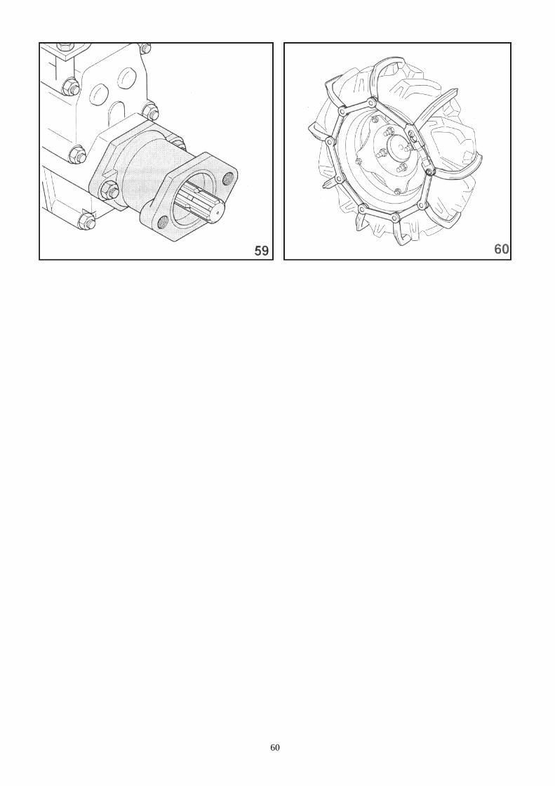
60
61
POSSIBILI INCONVENIENTI E LORO RIMEDI
TROUBLE SHOOTING
DEPANNAGE
POSIBLES INCONVENIENTES Y SOLUCIONES
MOGLICHE STORUNGEN UND DEREN ABHILFE
62
• regolare la frizione svitando la vite di registro B (fig.24) fino adottenere un buon distacco della frizione.
• adjust the clutch, unscrewing adjusting screw B (fig.24) untilthe clutch disengages properly.
• régler l’embrayage en dévissant la vis de réglage B (fig.24)jusqu’à obtenir un bon détachement de l’embrayage.
• regular el embrague destornillando el tornillo de regulación B(fig.24) hasta obtener una buena distancia del embrague.
• Die Kupplung durch Losschrauben der Stellschraube B (Bild24) so einstellen, daß die Kupplung gut abhebt.
4) Macchina con fresa: la macchina nei terreni duri salta in avanti;
4) Machine with rotary hoe: the machine jumps forward in hardground.
4) Machine avec fraise: la machine sur les terrains durs sauteen avant;
4) Máquina con fresa: la máquina en terrenos duros salta haciaadelante:
5) Macchina con barra falciante: si rompe frequentemente l’attacco lama;
63
4) Maschine mit Anbaufräse: auf hartem Böden bewegt sichdas Gerät sprungweise fort:
ataco cuchilla;

64
PERIODI DI LUNGA INATTIVITA’
STORAGE
REMISAGE
PERIODOS DE LARGA INACTIVIDAD
LANGERER STILLSTAND DER MASCHINE
65
COME SOSTITUIRE LA FRIZIONE (figura 69)
1 - Montare la frizione sul motore
2 - Posizionare la leva frizione A sulla macchina.
3 - Accostare il motore con la frizione alla scatola cambio efissarlo, avendo cura che i due denti dell’anello reggispinta(B) siano posizionati in basso come indicato in figura 69.
4 - Collegare il cavo di comando frizione.
5 - Per la registrazione vedere pag.27.
ATTENZIONE!
Non smontare mai la frizione nei suoi particolari interni perché,essendoci molle fortemente precaricate, lo smontaggio senza leapposite attrezzature può risultare pericoloso.
NOTAAl termine del lavoro si consiglia di lasciare la macchina conla frizione disinnestata, azionando cioè la leva frizione e bloc-candola con l’apposita molletta di fermo C (fig.70).
HOW TO REPLACE THE CLUTCH (picture 69)
1 - Mount the clutch on the motor
2 - Position clutch lever A on the machine.
3 - Approach the motor with the clutch to the gear box and fixit, paying attention that the two teeth of the push-holder ring(B) are low as indicated in the picture 69.
4 - Connect the clutch driving cable.
5 - For adjustments refer to page 27.
ATTENTION !
Never disassemble the inner parts of the clutch since, beingthe spring strongly charged, it would be dangerous to disas-semble the unit without the fit equipment.
NOTAAt the end of the operation, it is advisable to let the machinewith the clutch disengaged, that is actionning the clutch leverand blocking it with the fit stop bracket C (fig.70).
COMMENT SUBSTITUER LA FRICTION (figure 69)
1 - Monter la friction sur le moteur.
2 - Positionner le levier friction sur la machine.
3 - Approcher le moteur avec la friction de le boîte de vitesse etle fixer, en se soignant que les deux dents de l’anneau soutien-poussées (B) soient situés en bas comme indiqué dans la figu-re 69.
4 - Accoupler le câble de commande friction.
5 - Pour l’enregistration voir à la page 27.
ATTENTION ! Ne démonter jamais la friction dans ses particuliers intérieuresparce que il y des ressorts fortement prechargé et cette opé-ration peut être très dangereuse si conduite sans un outillageapte a ce bût. NOTE A la fin du travail, on conseille de laisser la machine à lafriction débrayée, c’est a dire en actionnant le levier friction,en le bloqueant par le ressort d’arrêt C (fig.70).
COMO SUBSTITUIR EL EMBRAGUE (figura 69)
1 - Montar el embrague sobre el motor.
2 - Colocar la palanca embrague A sobre la máquina.
3 - Acercar el motor con el embrague a la caja del cambio yfijarlo, asegurandose que los dos dientes de el anillo cojinetedel tope (B) sean puestos en bajo como indicado por la fig.69.
4 - Conexionar el cable de mando embrague.
5 - Para la registración ver a la pagina 27.
ATENCIÓN !
No desmontar nunca el embrague en sus particulares inter-nos porqué hay unos resortes fuertemente cargadas, y estaoperación puede ser muy peligrosa si efectuada sin los ape-ros adecuados.
NOTAA la fin del trabajo, aconsejamos de dejar la máquina con elembrague desenchufado, o sea accionando la palanca em-brague y bloqueandolo con el resorte de firme C (fig.70).
ERSATZEN DER KUPPLUNG (bild 69)
1 - Montieren Sie die Kupplung auf den Motor.
2 - Stellen Sie den Kupplungshebel A auf die Maschine ein.
3 - Nähern Sie den Motor mit der Kupplung auf das Getriebe-gehäuse und fixieren, die zwei Zähne des Drucklagersrings(B) müssen unten festgestellt werden (siehe Bild 69).
4 - Verbinden Sie das Kabel der Kupplungsdrehen.
5 - Siehe Seite 27 für die Einstellung.
VORSICHT ! Die inneren Teilen der Kupplung nie abmontieren, der Ausein-anderbau ohne die bezüglichen Vorrichtung kann gefährlichsein, da die Feder stark gespannte sind. NOTE Am Ende der Arbeit es ist ratsam die Maschine mit entkuppelteKupplung zu lassen, d.h. das Kupplungshebel antrieben undsie mit der bezüglichen Festellvorrichtung blockieren (Bild 70).
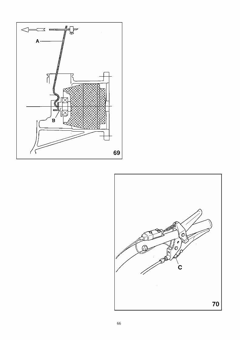
66

67
DOTAZIONE GARANZIA
Ogni macchina viene corredata di:
1 Manuale uso e manutenzione motore1 serie di chiavi per il motore1 Manuale uso e manutenzione macchina1 serie di chiavi per la macchina
La garanzia è riconosciuta nei termini e modi specificati suidocumenti allegati alla dotazione della macchina.
In caso di impiego per noleggio, la garanzia non è riconosciuta.
Nota: la garanzia del motore è riconosciuta dal costruttore delmotore stesso, nei termini e modi specificati sui documenti al-legati alla dotazione della macchina.
TOOL KIT GUARANTEE Each machine comes supplied with: 1 Use and maintenance manual for engine 1 Set of spanner for the engine 1 Use and maintenance manual for machine 1 Set of spanner for the machine
BCS guarantee is recognized according to the terms andrules indicated on the documents furnished with the machine.
For rental use, warranty is nor granted.
Note: the engine guarantee is recognizedby the builder of theengine according to the terms and rules indicated on thedocuments furnished with the machine.
OUTILLAGE GARANTIE
Chaque machine est delivré avec:
1 Manuel d’usage et d’entretien du moteur1 Série de clefs pour le moteur1 Manuel d’usage et d’entretien de la machine1 Série de clefs pour la machine
La garantie est reconnue selon les modes et termes indiquéssur les documents fournis avec la machine.
En cas de location, la garantie n’est pas reconnue.
Note: la garantie du moteur est reconnue par le constructeurdu moteur selon les modes et termes indiqués sur les docu-ments fournis avec la machine.
DOTACIONES GARANTIA
Cada máquina viene equipada de:
1 Manual de uso y manutención del motor1 Serie de llaves para el motor1 Manual de uso y manutención de la máquina1 Serie de llaves para la máquina
La garantia es reconocida en término y modo especificadossobre documentos adjunto a la dotaciòn de la máquina.
En caso de empleo para alquier, la garantia no tiendrà valor.
Nota: la garantia del motor es reconocida por el constructordel mismo, en término y modo especificados sobre documen-tos adjunto a la dotaciòn de la máquina.
STANDARD ZUBEHOR GARANTIE
Jeder Maschine ist mit folgendem Standardzubehörausgestattet:
1 Betriebsanleitung und Wartungshandbuch für den Motor1 Satz Bedienungsschlussel für den Motor1 Betriebsanleitung und Wartungshandbuch für die Maschine1 Satz Bedienungsschlussel für die Maschine
Die Garantie wird gemass der mit der Maschine mitgeliefertenUnterlage anerkannt.
Im Mietfall ist die Garantie nicht anerkannt.
Anmerkung: Die Garantie auf den Motor wird vom Werk selbstgelestet; siehe mitgelieferte Dokumentation.

68
CERTIFICATI E DICHIARAZIONI (dove previsti)
CERTIFICATES AND DECLARATIONS (if foreseen)
CERTIFICATS ET DECLARATIONS (si prevu)
CERTIFICADOS Y DECLARACIONES (donde està previsto)
BESCHEINIGUNGEN UND DEKLARATION (Wenn vorgesehen)

69
PARTICOLARI DI CONSUMO
PARTICOLARI SOGGETTI A SOSTITUZIONE PER USURA:
- coltelli frese (laterali e centrali) - lame barre falcianti e sezioni lama - denti barre falcianti - attacchi lama - lame per tosaerba - slitte di regolazione altezza di taglio - slitte di scorrimento a terra
PARTICOLARI SOGGETTI A SOSTITUZIONE PERMANUTENZIONE PERIODICA:
- filtri olio motore - filtri carburante - filtri aria motore - olio cambio - olio motore - olio trasmissione attrezzi - cinghie di trasmissione
CONSUMABLES PARTS TO BE REPLACED BECUASE WORN OUT: - Rotary hoe knives (side and central knives) - Cutter bars and cutter section - Cutter bars tooth - Cutter bars hitches - Lawn mowers cutting bars - Adjustment slides for cutting height - Floor sliding slides
PARTS WHICH MUST BE REPLACED FOR PERIODICALMAINTENANCE PROCEDURES:
- Motor oil filters - Carburator filters - Motor air filters - Gear box oil - Motor oil - Implements transmission oil - Transmission belts
SUYET A USURE
PIECES A CHANGER POUR USURE:
- couteaux des fraises (láteraux et centraux) - lame barre faucheuses et lame fixe - dents des barres fauchantes - attache lame - lame pour tondeuse - glissières de réglage des hauteurs de coupe - glissières de frottolement sur le terrain
PIECES A CHANGER LORS DES CONTROLESPERIODIQUE DE LA MACHINE:
- filtres à huile moteur - filtres carburant - filtres à air moteur - huile de la boite de vitesses - huile du moteur - huile de la transmission des outillage - courroies de transmission
PARTICULARES DE DESGASTE
PARTICULARES EXPUESTOS A DESGASTE:
- Cuchillos fresas (laterales y centrales) - Hojas lamas segadoras y seccion hojas - Dientes lamas segadoras - Enganches lamas - Lamas cortahierba - Trineos regulación hancho de corte - Trineos deslizamiento a tierra
PARTICULARES EXPUESTOS A SUBSTITUCION PORMANUTENCIÓN PERÍODICA:
- Filtros aceite motor - Filtros carburante - Filtros aire motor - Aceite cambio - Aceite motor - Aceite transmisión implementos - Correos de transmisión
VERBRAUCHEN TEILE
VERBRAUCHBARE TEILE:
- Fräsen Messe (seitlich und zentral) - Mähbalken Messer und Messerschnitt - Mähbalkenszähnen - Messerskupplung - Messer für Rasenmäher - Einstellungsschlitten der Schnittshöhe - Schlitten für Bodensgleiten
TEILE DIE PERIODISCH ERSÄTZT WERDEN MÜSSEN:
- Motor Ölfilter - Brennstoffilter - Motorluftfilter - Wächselsöl - Geräteantriebsöl - Antriebsbänder - Treibriemen

MODALITA’ DI VENDITA DEI RICAMBIPer la richiesta dei pezzi di ricambio é necessario indica-re il codice completo del pezzo desiderato, così come in-dicato sulle tavole del catalogo ricambi presso i rivendi-tori autorizzati.Oltre questo è necessario indicare anche il numero di se-rie della macchina (vedi pag.6, fig.A).
N° DI SERIE
La BCS si riserva il diritto di apportare, in qualsiasi mo-mento e senza preavviso, eventuali modifiche di compo-nenti od accessori che ritenesse necessarie per esigenzetecniche o commerciali.
BCS S.p.A.
ORDERING SPARE PARTSWhen ordering spare parts, be sure to give the completecode of the part required to the authorised dealers as gi-ven in the parts catalogue.The serial number of the machine or of the implementmust also be given (see page 6, fig. A).
CODE NUMBER
BCS S.p.A. reserves the right to modify at any time andwithout notice any parts of accessory, if necessary fromtechnical or commercial point of view.
BCS S.p.A.
MODALITE DE VENTE DES PIECES DE RECHANGEPour la commande des pièces de rechange, il est néces-saire d’indiquer le code complet de la pièce désirée, ense reportant aux tables des pièces de rechange du cata-logue chez les revendeurs autorisès.Outre cela, il est également nécessaire d’indiquer le n°d’immatriculation de la machine (voir page 6, fig. A).
NUMERO DE MATR.
La BCS S.p.A. se réserve le droit d’apporter à tout mo-ment at sans préavis, d’éventuelles modifications auxpièces et aux accessoires considérés nécessaire sur leplan technique ou commercial. BCS S.p.A.
SOLICITUD DE RECAMBIOSPara la solicitud de las piezas de recambio es necesarioindicar el código completo de la pieza deseada, en la for-ma indicada en la tabla del cátalogo recambios a travésde los distributores autorizados.Además es necesario indicar el número de matrícula dela máquina (ver pag.6, fig. A).
NUMERO DE MATR.
La BCS S.p.A. se reserva el derecho de efectuar en cual-quier momento, y sin previo aviso, modificación de com-ponentes o accesorios que considere necesaria por exi-géncias técnicas ó comerciales.
BCS S.p.A.
VERKAUF DER ERSATZTEILEBei der Anforderung von Ersatzteilen muß die vollständi-ge Kennummer des gewünschten Teiles den anerkanntenhändler angegeben werden, die den Tabellen des Ersatz-teilkatalogs zu entnehmen ist.Darüberhinaus ist auch die Zulassungsnummer der Ma-schine anzugeben (siehe Seite 6, Bild A).
KODEZAHL
Firma BCS S.p.A. behält sich jederzeit ohne Vorankündi-gung eventuelle Änderungen bezüglich von Bau oder Zu-satzteilen vor, die sie aus technischen oder kommerziel-len Gründen für notwendig erachtet. BCS S.p.A.
70

Note:
……………………………………………………………………………………………………………….
……………………………………………………………………………………………………………….
……………………………………………………………………………………………………………….
……………………………………………………………………………………………………………….
……………………………………………………………………………………………………………….
……………………………………………………………………………………………………………….
……………………………………………………………………………………………………………….
……………………………………………………………………………………………………………….
……………………………………………………………………………………………………………….
……………………………………………………………………………………………………………….
……………………………………………………………………………………………………………….
……………………………………………………………………………………………………………….
……………………………………………………………………………………………………………….
……………………………………………………………………………………………………………….
……………………………………………………………………………………………………………….
……………………………………………………………………………………………………………….
……………………………………………………………………………………………………………….
……………………………………………………………………………………………………………….
……………………………………………………………………………………………………………….
……………………………………………………………………………………………………………….
……………………………………………………………………………………………………………….
……………………………………………………………………………………………………………….
……………………………………………………………………………………………………………….
……………………………………………………………………………………………………………….
……………………………………………………………………………………………………………….
……………………………………………………………………………………………………………….

HERSTELLER – CONSTRUCTOR – CONSTRUCTEUR – MANUFACTURER – COSTRUTTORE
BCS S.p.a.Viale Mazzini, 161
20081 ABBIATEGRASSO – MILANO – ItalyTel. (02) 9482.1 – Telefax (02) 94960800
http://www.bcs-ferrari.it
BCS IBERICA S.p.A.Poligono Industrial
S.ta Margarita – c/Llobregat, 15TERRASSA – Barcellona – Spagna
Tel. 7830544 – Telefax 7851203e-mail: [email protected]
BCS AMERICA LLC8111 N.E. Columbia Blvd
Portland , OR 97218 U.S.A.Tel. 503 - 2521249 / 800 – 5431040
Fax: 503-2528360http://www.bcs-america.com