670 series version 2.2 ansi installation manual · disclaimer this document has been carefully...
TRANSCRIPT

Relion® 670 SERIES
670 seriesVersion 2.2 ANSIInstallation manual


Document ID: 1MRK 514 026-UUS Issued: May 2019
Revision: G Product version: 2.2
© Copyright 2017 ABB. All rights reserved

Copyright
This document and parts thereof must not be reproduced or copied without written permissionfrom ABB, and the contents thereof must not be imparted to a third party, nor used for anyunauthorized purpose.
The software and hardware described in this document is furnished under a license and may beused or disclosed only in accordance with the terms of such license.
This product includes software developed by the OpenSSL Project for use in the OpenSSL Toolkit.(http://www.openssl.org/) This product includes cryptographic software written/developed by:Eric Young ([email protected]) and Tim Hudson ([email protected]).
Trademarks
ABB and Relion are registered trademarks of the ABB Group. All other brand or product namesmentioned in this document may be trademarks or registered trademarks of their respectiveholders.
Warranty
Please inquire about the terms of warranty from your nearest ABB representative.

Disclaimer
This document has been carefully checked by ABB but deviations cannot be completely ruled out.In case any errors are detected, the reader is kindly requested to notify the manufacturer. Otherthan under explicit contractual commitments, in no event shall ABB be responsible or liable for anyloss or damage resulting from the use of this manual or the application of the equipment.

Conformity
This product complies with the directive of the Council of the European Communities on theapproximation of the laws of the Member States relating to electromagnetic compatibility (EMCDirective 2004/108/EC) and concerning electrical equipment for use within specified voltagelimits (Low-voltage directive 2006/95/EC). This conformity is the result of tests conducted by ABBin accordance with the product standard EN 60255-26 for the EMC directive, and with the productstandards EN 60255-1 and EN 60255-27 for the low voltage directive. The product is designed inaccordance with the international standards of the IEC 60255 series and ANSI C37.90.

Table of contents
Section 1 Introduction..............................................................................................................51.1 This manual................................................................................................................................................51.2 Intended audience.................................................................................................................................... 51.3 Product documentation.......................................................................................................................... 61.3.1 Product documentation set...............................................................................................................61.3.2 Document revision history................................................................................................................. 71.3.3 Related documents..............................................................................................................................81.4 Document symbols and conventions................................................................................................. 101.4.1 Symbols................................................................................................................................................ 101.4.2 Document conventions..................................................................................................................... 10
Section 2 Safety information.................................................................................................132.1 Symbols on the product........................................................................................................................ 132.2 Warnings................................................................................................................................................... 132.3 Caution signs...........................................................................................................................................142.4 Note signs................................................................................................................................................ 15
Section 3 Environmental aspects..........................................................................................173.1 Sustainable development......................................................................................................................173.2 Disposing of the IED...............................................................................................................................17
Section 4 Unpacking, inspecting and storing..................................................................... 194.1 Removing transport packaging........................................................................................................... 194.2 Inspecting the product.......................................................................................................................... 194.2.1 Identifying the product..................................................................................................................... 194.2.2 Checking delivery items.................................................................................................................... 194.2.3 Inspecting the IED.............................................................................................................................. 194.2.4 Returning an IED damaged in transit............................................................................................. 194.3 Storing...................................................................................................................................................... 20
Section 5 Mounting................................................................................................................. 215.1 Required tools..........................................................................................................................................215.2 Checking environmental conditions and mounting space.............................................................215.3 Mounting the IED.................................................................................................................................... 215.3.1 Flush mounting...................................................................................................................................225.3.1.1 Overview........................................................................................................................................... 225.3.1.2 Mounting procedure for flush mounting................................................................................... 235.3.2 19” panel rack mounting................................................................................................................... 235.3.2.1 Overview........................................................................................................................................... 23
Table of contents
670 series 1Installation manual
© Copyright 2017 ABB. All rights reserved

5.3.2.2 Mounting procedure for 19” panel rack mounting...................................................................245.3.3 Wall mounting..................................................................................................................................... 255.3.3.1 Overview........................................................................................................................................... 255.3.3.2 Mounting procedure for wall mounting..................................................................................... 255.3.3.3 How to reach the rear side of the IED.........................................................................................255.3.4 Side-by-side 19” rack mounting...................................................................................................... 265.3.4.1 Overview........................................................................................................................................... 265.3.4.2 Mounting procedure for side-by-side rack mounting............................................................. 275.3.4.3 IED mounted with a RHGS6 case................................................................................................. 275.3.5 Side-by-side flush mounting............................................................................................................285.3.5.1 Overview........................................................................................................................................... 285.3.5.2 Mounting procedure for side-by-side flush mounting............................................................295.3.6 Mounting the injection unit REX060 (REG670 only)....................................................................295.3.7 Mounting the coupling capacitor unit REX061 and shunt resistor unit REX062
(REG670 only)......................................................................................................................................305.3.7.1 Coupling capacitor unit REX061.................................................................................................. 305.3.7.2 Shunt resistor unit REX062........................................................................................................... 31
Section 6 Connecting..............................................................................................................336.1 Making the electrical connection.........................................................................................................336.1.1 IED connectors....................................................................................................................................336.1.1.1 Overview........................................................................................................................................... 336.1.1.2 Front side connectors....................................................................................................................356.1.1.3 Rear side connectors......................................................................................................................366.1.1.4 Connection examples for high impedance differential protection...................................... 476.1.2 Connecting to protective ground...................................................................................................496.1.3 Connecting the power supply module...........................................................................................496.1.4 Connecting to CT and VT circuits................................................................................................... 506.1.5 Connecting the binary input and output signals......................................................................... 516.1.6 Making the shield connection..........................................................................................................536.2 Making the electrical connection to the rotor and stator injection equipment (REG670
only)...........................................................................................................................................................556.2.1 Connectors for injection unit REX060, coupling capacitor unit REX061 and shunt
resistor unit REX062..........................................................................................................................556.2.1.1 Injection unit REX060.....................................................................................................................556.2.1.2 Coupling capacitor unit REX061...................................................................................................576.2.1.3 Shunt resistor unit REX062...........................................................................................................596.2.2 Connecting injection unit REX060, coupling capacitor unit REX061 and shunt
resistor unit REX062..........................................................................................................................606.2.3 Connecting and setting voltage inputs.........................................................................................656.3 Making of Ethernet connections......................................................................................................... 676.3.1 Connecting station communication interfaces........................................................................... 676.3.2 Connecting remote communication interfaces LDCM...............................................................686.4 Installing the serial communication cable for RS485......................................................................69
Table of contents
2 670 seriesInstallation manual
© Copyright 2017 ABB. All rights reserved

6.4.1 RS485 serial communication module............................................................................................ 696.4.2 Installing the serial communication cable for RS485 SPA/IEC................................................. 726.4.3 Data on RS485 serial communication module cable...................................................................746.5 Installing the GPS antenna....................................................................................................................756.5.1 Antenna installation...........................................................................................................................756.5.2 Electrical installation......................................................................................................................... 766.5.3 Lightning protection......................................................................................................................... 76
Section 7 Checking installation.............................................................................................777.1 Identifying hardware and software version...................................................................................... 777.2 Checking mounting................................................................................................................................ 777.3 Checking the power supply...................................................................................................................777.4 Energizing the IED.................................................................................................................................. 77
Section 8 Removing, repairing and exchanging..................................................................798.1 Product lifecycle......................................................................................................................................798.2 Checking IED information.....................................................................................................................798.3 Removing the IED................................................................................................................................... 798.4 Sending the IED for repair.................................................................................................................... 798.5 Exchanging the IED................................................................................................................................ 79
Section 9 Technical data........................................................................................................ 819.1 Dimensions.............................................................................................................................................. 819.1.1 Case without protective cover.........................................................................................................819.1.2 Case with protective cover...............................................................................................................839.1.3 Flush mounting dimensions............................................................................................................ 869.1.4 Side-by-side flush mounting dimensions..................................................................................... 879.1.5 Wall mounting dimensions.............................................................................................................. 88
Section 10 Glossary.................................................................................................................. 89
Table of contents
670 series 3Installation manual
© Copyright 2017 ABB. All rights reserved

4

Section 1 Introduction
1.1 This manualGUID-AB423A30-13C2-46AF-B7FE-A73BB425EB5F v19
The installation manual contains instructions on how to install the IED. The manual providesprocedures for mechanical and electrical installation. The chapters are organized in thechronological order in which the IED should be installed.
1.2 Intended audienceGUID-C9B8127F-5748-4BEA-9E4F-CC762FE28A3A v11
This manual addresses the personnel responsible for installing the product hardware.
The installation personnel must have basic knowledge of handling electronic equipment.
1MRK 514 026-UUS G Section 1Introduction
670 series 5Installation manual
© Copyright 2017 ABB. All rights reserved

1.3 Product documentation
1.3.1 Product documentation setGUID-3AA69EA6-F1D8-47C6-A8E6-562F29C67172 v16
IEC07000220-4-en.vsd
Plan
ning
& p
urch
ase
Engi
neer
ing
Inst
allin
g
Com
mis
sion
ing
Ope
ratio
n
Mai
nten
ance
Dec
omm
issi
onin
gD
eins
tallin
g &
disp
osal
Application manual
Operation manual
Installation manual
Engineering manual
Communication protocol manual
Cyber security deployment guideline
Technical manual
Commissioning manual
IEC07000220 V4 EN-US
Figure 1: The intended use of manuals throughout the product lifecycle
The engineering manual contains instructions on how to engineer the IEDs using the various toolsavailable within the PCM600 software. The manual provides instructions on how to set up aPCM600 project and insert IEDs to the project structure. The manual also recommends a sequencefor the engineering of protection and control functions, as well as communication engineering forIEC 61850.
The installation manual contains instructions on how to install the IED. The manual providesprocedures for mechanical and electrical installation. The chapters are organized in thechronological order in which the IED should be installed.
The commissioning manual contains instructions on how to commission the IED. The manual canalso be used by system engineers and maintenance personnel for assistance during the testingphase. The manual provides procedures for the checking of external circuitry and energizing theIED, parameter setting and configuration as well as verifying settings by secondary injection. Themanual describes the process of testing an IED in a substation which is not in service. Thechapters are organized in the chronological order in which the IED should be commissioned. Therelevant procedures may be followed also during the service and maintenance activities.
Section 1 1MRK 514 026-UUS GIntroduction
6 670 seriesInstallation manual
© Copyright 2017 ABB. All rights reserved
The operation manual contains instructions on how to operate the IED once it has beencommissioned. The manual provides instructions for the monitoring, controlling and setting of theIED. The manual also describes how to identify disturbances and how to view calculated andmeasured power grid data to determine the cause of a fault.
The application manual contains application descriptions and setting guidelines sorted perfunction. The manual can be used to find out when and for what purpose a typical protectionfunction can be used. The manual can also provide assistance for calculating settings.
The technical manual contains operation principle descriptions, and lists function blocks, logicdiagrams, input and output signals, setting parameters and technical data, sorted per function.The manual can be used as a technical reference during the engineering phase, installation andcommissioning phase, and during normal service.
The communication protocol manual describes the communication protocols supported by theIED. The manual concentrates on the vendor-specific implementations.
The point list manual describes the outlook and properties of the data points specific to the IED.The manual should be used in conjunction with the corresponding communication protocolmanual.
The cyber security deployment guideline describes the process for handling cyber security whencommunicating with the IED. Certification, Authorization with role based access control, andproduct engineering for cyber security related events are described and sorted by function. Theguideline can be used as a technical reference during the engineering phase, installation andcommissioning phase, and during normal service.
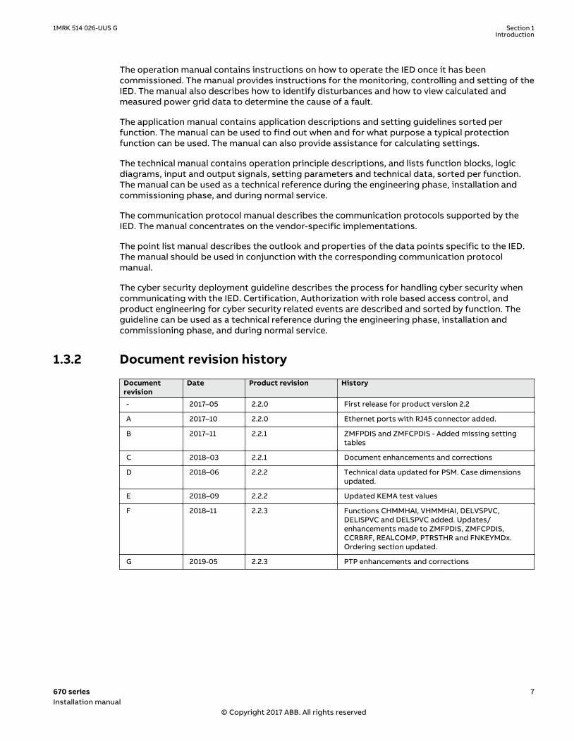
1.3.2 Document revision historyGUID-34B323E4-1319-4D42-80CE-29B0F2D36E2C v2
Documentrevision
Date Product revision History
- 2017–05 2.2.0 First release for product version 2.2
A 2017–10 2.2.0 Ethernet ports with RJ45 connector added.
B 2017–11 2.2.1 ZMFPDIS and ZMFCPDIS - Added missing settingtables
C 2018–03 2.2.1 Document enhancements and corrections
D 2018–06 2.2.2 Technical data updated for PSM. Case dimensionsupdated.
E 2018–09 2.2.2 Updated KEMA test values
F 2018–11 2.2.3 Functions CHMMHAI, VHMMHAI, DELVSPVC,DELISPVC and DELSPVC added. Updates/enhancements made to ZMFPDIS, ZMFCPDIS,CCRBRF, REALCOMP, PTRSTHR and FNKEYMDx.Ordering section updated.
G 2019-05 2.2.3 PTP enhancements and corrections
1MRK 514 026-UUS G Section 1Introduction
670 series 7Installation manual
© Copyright 2017 ABB. All rights reserved

1.3.3 Related documentsGUID-94E8A5CA-BE1B-45AF-81E7-5A41D34EE112 v7
Documents related to REB670 Document numbers
Application manual 1MRK 505 370-UUS
Commissioning manual 1MRK 505 372-UUS
Product guide 1MRK 505 373-BEN
Technical manual 1MRK 505 371-UUS
Type test certificate 1MRK 505 373-TUS
Documents related to REC670 Document numbers
Application manual 1MRK 511 401-UUS
Commissioning manual 1MRK 511 403-UUS
Product guide 1MRK 511 404-BEN
Technical manual 1MRK 511 402-UUS
Type test certificate 1MRK 511 404-TUS
Documents related to RED670 Document numbers
Application manual 1MRK 505 376-UUS
Commissioning manual 1MRK 505 378-UUS
Product guide 1MRK 505 379-BEN
Technical manual 1MRK 505 377-UUS
Type test certificate 1MRK 505 379-TUS
Documents related to REG670 Document numbers
Application manual 1MRK 502 071-UUS
Commissioning manual 1MRK 502 073-UUS
Product guide 1MRK 502 074-BEN
Technical manual 1MRK 502 072-UUS
Type test certificate 1MRK 502 074-TUS
Documents related to REL670 Document numbers
Application manual 1MRK 506 369-UUS
Commissioning manual 1MRK 506 371-UUS
Product guide 1MRK 506 372-BEN
Technical manual 1MRK 506 370-UUS
Type test certificate 1MRK 506 372-TUS
Section 1 1MRK 514 026-UUS GIntroduction
8 670 seriesInstallation manual
© Copyright 2017 ABB. All rights reserved

Documents related to RET670 Document numbers
Application manual 1MRK 504 163-UUS
Commissioning manual 1MRK 504 165-UUS
Product guide 1MRK 504 166-BEN
Technical manual 1MRK 504 164-UUS
Type test certificate 1MRK 504 166-TUS
Documents related to RES670 Document numbers
Application manual 1MRK 511 407-UUS
Commissioning manual 1MRK 511 409-UUS
Product guide 1MRK 511 410-BEN
Technical manual 1MRK 511 408-UUS
Type test certificate 1MRK 511 410-TUS
Documents related to RER670 Document numbers
Application manual
Commissioning manual
Product guide 1MRK 506 378-BEN
Technical manual
Type test certificate
670 series manuals Document numbers
Operation manual 1MRK 500 127-UUS
Engineering manual 1MRK 511 398-UUS
Installation manual 1MRK 514 026-UUS
Communication protocol manual, DNP3 1MRK 511 391-UUS
Communication protocol manual, IEC 61850 Edition 2 1MRK 511 393-UEN
Point list manual, DNP3 1MRK 511 397-UUS
Accessories guide 1MRK 514 012-BUS
Connection and Installation components 1MRK 513 003-BEN
Test system, COMBITEST 1MRK 512 001-BEN
1MRK 514 026-UUS G Section 1Introduction
670 series 9Installation manual
© Copyright 2017 ABB. All rights reserved

1.4 Document symbols and conventions
1.4.1 SymbolsGUID-2945B229-DAB0-4F15-8A0E-B9CF0C2C7B15 v13
The electrical warning icon indicates the presence of a hazard which could result inelectrical shock.
The warning icon indicates the presence of a hazard which could result in personalinjury.
The caution hot surface icon indicates important information or warning about thetemperature of product surfaces.
The caution icon indicates important information or warning related to theconcept discussed in the text. It might indicate the presence of a hazard whichcould result in corruption of software or damage to equipment or property.
The information icon alerts the reader of important facts and conditions.
The tip icon indicates advice on, for example, how to design your project or how touse a certain function.
Although warning hazards are related to personal injury, it is necessary to understand that undercertain operational conditions, operation of damaged equipment may result in degraded processperformance leading to personal injury or death. It is important that the user fully complies with allwarning and cautionary notices.
1.4.2 Document conventionsGUID-96DFAB1A-98FE-4B26-8E90-F7CEB14B1AB6 v8
• Abbreviations and acronyms in this manual are spelled out in the glossary. The glossary alsocontains definitions of important terms.
• Push button navigation in the LHMI menu structure is presented by using the push buttonicons.
For example, to navigate between the options, use and .• HMI menu paths are presented in bold.
For example, select Main menu/Settings.• LHMI messages are shown in Courier font.
For example, to save the changes in non-volatile memory, select Yes and press .• Parameter names are shown in italics.
Section 1 1MRK 514 026-UUS GIntroduction
10 670 seriesInstallation manual
© Copyright 2017 ABB. All rights reserved

For example, the function can be enabled and disabled with the Operation setting.• Each function block symbol shows the available input/output signal.
• the character ^ in front of an input/output signal name indicates that the signal namemay be customized using the PCM600 software.
• the character * after an input signal name indicates that the signal must be connectedto another function block in the application configuration to achieve a valid applicationconfiguration.
• Dimensions are provided both in inches and millimeters. If it is not specifically mentionedthen the dimension is in millimeters.
1MRK 514 026-UUS G Section 1Introduction
670 series 11Installation manual
© Copyright 2017 ABB. All rights reserved

12

Section 2 Safety information
2.1 Symbols on the productGUID-E48F2EC3-6AB8-4ECF-A77E-F16CE45CA5FD v4
All warnings must be observed.
Read the entire manual before doing installation or any maintenance work on theproduct.
Class 1 Laser product. Take adequate measures to protect your eyes and do notview directly with optical instruments.
Do not touch the unit in operation. The installation shall take into account theworst case temperature.
2.2 WarningsIP1504-1 v2
Observe the warnings during all types of work related to the product.GUID-C9B6638A-57E7-4E05-9A33-A60E359C54AF v1
Only electrically skilled persons with the proper authorization and knowledge ofany safety hazards are allowed to carry out the electrical installation.
M2366-2 v2
National and local electrical safety regulations must always be followed. Working ina high voltage environment requires serious approach to avoid human injuries anddamage to equipment.
M2362-2 v1
Do not touch circuitry during operation. Potentially lethal voltages and currents arepresent.
M2364-2 v1
Always use suitable isolated test pins when measuring signals in open circuitry.Potentially lethal voltages and currents are present.
1MRK 514 026-UUS G Section 2Safety information
670 series 13Installation manual
© Copyright 2017 ABB. All rights reserved

M2370-2 v1
Never connect or disconnect a wire and/or a connector to or from a IED duringnormal operation. Hazardous voltages and currents are present that may be lethal.Operation may be disrupted and IED and measuring circuitry may be damaged.
GUID-BEDD698E-356C-4CF9-9DAE-64DB3CEADEAD v1
Dangerous voltages can occur on the connectors, even though the auxiliary voltagehas been disconnected.
M2369-2 v3
Always connect the IED to protective ground, regardless of the operatingconditions. This also applies to special occasions such as bench testing,demonstrations and off-site configuration. This is class 1 equipment that shall begrounded.
M2367-2 v1
Never disconnect the secondary connection of current transformer circuit withoutshort-circuiting the transformer’s secondary winding. Operating a currenttransformer with the secondary winding open will cause a massive potential build-up that may damage the transformer and may cause injuries to humans.
M2372-2 v1
Never remove any screw from a powered IED or from a IED connected to poweredcircuitry. Potentially lethal voltages and currents are present.
SEMOD168311-3 v1
Take adequate measures to protect the eyes. Never look into the laser beam.
GUID-11CCF92B-E9E7-409C-84D0-DFDEA1DCBE85 v2
The IED with accessories should be mounted in a cubicle in a restricted access areawithin a power station, substation or industrial or retail environment.
2.3 Caution signsIP1503-1 v1
GUID-5D1412B8-8F9D-4D39-B6D1-60FB35797FD0 v2
Whenever changes are made in the IED, measures should be taken to avoidinadvertent tripping.
GUID-F2A7BD77-80FB-48F0-AAE5-BE73DE520CC2 v1
The IED contains components which are sensitive to electrostatic discharge. ESDprecautions shall always be observed prior to touching components.
Section 2 1MRK 514 026-UUS GSafety information
14 670 seriesInstallation manual
© Copyright 2017 ABB. All rights reserved

M2695-2 v2
Always transport PCBs (modules) using certified conductive bags.
M2696-2 v1
Do not connect live wires to the IED. Internal circuitry may be damaged
M2697-2 v2
Always use a conductive wrist strap connected to protective ground whenreplacing modules. Electrostatic discharge (ESD) may damage the module and IEDcircuitry.
M2698-2 v2
Take care to avoid electrical shock during installation and commissioning.
M2693-2 v1
Changing the active setting group will inevitably change the IEDs operation. Becareful and check regulations before making the change.
GUID-3BEE51C6-8793-4C89-B8A8-07D0FA6EE4CA v3
Avoid touching the enclosure of the coupling capacitor REX061 unit and the shuntresistor REX062 unit. The surface may be hot during normal operation. Thetemperature can rise 50°C in REX061 and 65°C in REX062 above the ambienttemperature.
2.4 Note signsIP1497-1 v1
M19-2 v3
Observe the maximum allowed continuous current for the different currenttransformer inputs of the IED. See technical data.
1MRK 514 026-UUS G Section 2Safety information
670 series 15Installation manual
© Copyright 2017 ABB. All rights reserved

16

Section 3 Environmental aspects
3.1 Sustainable developmentGUID-573C2931-CBB2-4E7D-A067-D8246CC7A52F v7
Sustainability has been taken into account from the beginning of the product design including thepro-environmental manufacturing process, long life time, operation reliability and disposing of theIED.
Operational reliability and long life time have been assured with extensive testing during thedesign and manufacturing processes. Moreover, long life time is supported by maintenance andrepair services as well as by the availability of spare parts.
Design and manufacturing have been done under a certified environmental system. Theeffectiveness of the environmental system is constantly evaluated by an external auditing body.We follow environmental rules and regulations systematically to evaluate their effect on ourproducts and processes.
3.2 Disposing of the IEDAMU0600460 v6
Definitions and regulations of hazardous materials are country-specific and change when theknowledge of materials increases. The materials used in this product are typical for electric andelectronic devices.
All parts used in this product are recyclable. When disposing of an IED or its parts contact a localwaste handler who is authorized and specialized in disposing electronic waste. These handlers cansort the material by using dedicated sorting processes and dispose of the product according tothe local requirements.
GUID-09CAB180-6D53-45E3-99EF-1AF5E357F41E v3
Table 1: Materials of the IED parts
IED Parts Material
Unit Metallic plates, parts and screws Steel and aluminum
Plastic parts PC1), LCP2)
Unit LHMI display module Various
Package Box Cardboard
Attached material Manuals Paper
1) Polycarbonate2) Liquid crystal polymer
1MRK 514 026-UUS G Section 3Environmental aspects
670 series 17Installation manual
© Copyright 2017 ABB. All rights reserved

18

Section 4 Unpacking, inspecting and storing
4.1 Removing transport packagingAMU0600514 v5
IEDs require careful handling.
1. Examine the delivered products to ensure that they have not been damaged during thetransport.
2. Remove the transport packing carefully without force.
The cardboard packaging material is 100% recyclable.
4.2 Inspecting the product
4.2.1 Identifying the productAMU0600513 v5
1. Locate the IED's order number from the label attached to the IED's case.2. Compare the IED's order number with the ordering information to verify that the received
product is correct.
4.2.2 Checking delivery itemsGUID-2A6D8F5A-470F-40D1-9EAE-60DE4DD85EE6 v1
Check that all items are included in the delivery in accordance with the delivery documents.
4.2.3 Inspecting the IEDGUID-F6333353-F05D-4B41-BE44-5CE5274E788E v2
• Check the IED to see if any damage occurred during transportation.
4.2.4 Returning an IED damaged in transitGUID-966A05ED-CD30-4F66-957E-00FF38943A73 v4
If damage has occurred during transport, appropriate actions must be taken against the latestcarrier. Please inform the nearest ABB office or representative. Notify ABB immediately if there areany discrepancies in relation to the delivery documents.
1MRK 514 026-UUS G Section 4Unpacking, inspecting and storing
670 series 19Installation manual
© Copyright 2017 ABB. All rights reserved

4.3 StoringGUID-1DC9D33D-DC62-438B-9333-3BB354164CBC v7
If the IED is stored before installation, it must be done in the original transport casing in a dry anddust free place in accordance with ANSI C37.90.0.Storage temperature must be within the range of-40° C to +70° C. The average high temperature is recommended to be less than +40° C, tominimize component ageing.
Section 4 1MRK 514 026-UUS GUnpacking, inspecting and storing
20 670 seriesInstallation manual
© Copyright 2017 ABB. All rights reserved

Section 5 Mounting
5.1 Required toolsGUID-B9478208-286B-4CFF-9C47-074D641A6F71 v2
Generally, all the screws included in delivered mounting kits are of Torx type and a torquescrewdriver of the same type is needed (Tx10, Tx15, Tx20, Tx25 and Tx30).
Use only the screws included in the mounting kit when mounting the plates and theangles on the IED. Screws with wrong dimension may damage the PCBs inside theIED.
5.2 Checking environmental conditions and mounting spaceGUID-2AF46E8C-25B3-4606-A768-E4B70E3D6B0A v11
The mechanical and electrical environmental conditions at the installation site must be within thelimits described in the technical manual and IEC60255-1, normal environment.
• Avoid installation in dusty, damp areas.• Check that sufficient space is available.
Sufficient space is needed at the front and rear of the IED to allow access to wires and opticalfibers and to enable maintenance and future modifications.
• Ensure convection cooling around the case to minimize the heating effect within the IED.
• Avoid installation in dusty, damp places and where combustible materials are presentnear the IED
5.3 Mounting the IEDM11978-3 v12
The IED can be rack, wall or flush mounted with the use of different mounting kits, see figure 2.
An additional box of type RHGS can be mounted to one side of a 1/2 or 3/4 IED.
The different mounting kits contain all parts needed including screws and assembly instructions.The following mounting kits are available:
• Flush mounting kit• 19” Panel (rack) mounting kit• Wall mounting kit• Side-by-side mounting kit
The same mounting kit is used for side-by-side rack mounting and side-by-side flush mounting.
The mounting kits are ordered with the IED from the ordering sheet in the Productguide. They are also available for ordering in the Accessories guide.
1MRK 514 026-UUS G Section 5Mounting
670 series 21Installation manual
© Copyright 2017 ABB. All rights reserved

A B C D
IEC06000147-4-en.vsdx
IEC06000147 V4 EN-US
Figure 2: Different mounting methods
Description
A Flush mounting
B 19” Panel rack mounting
C Wall mounting
D Side-by-side rack mounting
5.3.1 Flush mountingIP10303-1 v1
5.3.1.1 OverviewM11967-3 v5
The flush mounting kit can be used for case sizes:
• 1/2 x 19”• 3/4 x 19”• 1/1 x 19”• 1/4 x 19” (RHGS6 6U)
Only a single case can be mounted in each cut-out on the cubicle panel, for class IP54 protection.The screws from the IED shall be used to fasten the fasteners to the IED.
Flush mounting cannot be used for side-by-side mounted IEDs when IP54 classmust be fulfilled. Only IP20 class can be obtained when mounting two cases side-by-side in one (1) cut-out.
To obtain IP54 class protection, an additional factory mounted sealing must beordered when ordering the IED.
Section 5 1MRK 514 026-UUS GMounting
22 670 seriesInstallation manual
© Copyright 2017 ABB. All rights reserved

5.3.1.2 Mounting procedure for flush mountingM11942-2 v5
1
5
6
3
IEC16000080=1=en.vsd
2
4
IEC16000080 V1 EN-US
Figure 3: Flush mounting details.
PosNo Description Quantity Type
1 Sealing strip, used to obtain IP54class. The sealing strip is factorymounted between the case andfront plate.
- -
2 Fastener 2 -
3 Groove - -
4 Screw 4 M3x8 mm
5 Joining point of sealing strip - -
6 Panel - -
5.3.2 19” panel rack mountingIP10313-1 v1
5.3.2.1 OverviewSEMOD127656-5 v4
All IED sizes can be mounted in a standard 19” cubicle rack by using a suitably sized mounting kitconsisting of two mounting angles, their fastening screws and washers.
The mounting angles are reversible which enables mounting of IED size 1/2 x 19” or 3/4 x 19” eitherto the left or the right side of the cubicle.
A separately ordered rack mounting kit for side-by-side mounted IEDs or IEDstogether with RHGS cases should be selected so that the total size equals 19”.
1MRK 514 026-UUS G Section 5Mounting
670 series 23Installation manual
© Copyright 2017 ABB. All rights reserved

Use only the screws included in the mounting kit when mounting the plates and theangles on the IED. Screws with wrong dimension may damage the PCBs inside theIED.
5.3.2.2 Mounting procedure for 19” panel rack mountingM11948-2 v7
1a
IEC08000160-3-en.vsdx
1a
2
3
IEC08000160 V3 EN-US
Figure 4: 19” panel rack mounting details
The required torque for the screws is 3.5 Nm.
Section 5 1MRK 514 026-UUS GMounting
24 670 seriesInstallation manual
© Copyright 2017 ABB. All rights reserved

PosNo Description Quantity Type
1a, 1b Mounting angles, can be mounted eitherto the left or the right side of the case
2 -
2 Screw 8 M4x6
3 Washer 8 M4x6
5.3.3 Wall mountingIP10316-1 v1
5.3.3.1 OverviewM11973-3 v7
All case sizes, 1/2 x 19”, 3/4 x 19”, and 1/1 x 19”, can be wall mounted. It is also possible to mountthe IED on a panel or in a cubicle.
Use only the screws included in the mounting kit when mounting the plates and theangles on the IED. Screws with wrong dimension may damage the PCBs inside theIED.
If fiber cables are bent too much, the signal can be weakened. Wall mounting istherefore not recommended for any communication modules with fiberconnection.
5.3.3.2 Mounting procedure for wall mountingM11949-2 v3
Figure 5: Wall mounting details.
5.3.3.3 How to reach the rear side of the IEDM11941-2 v5
The IED can be equipped with a rear protection cover recommended to be used with this type ofmounting. See figure 6.
To reach the rear side of the IED, a free space of 3.2 inches is required on the unhinged side.
1MRK 514 026-UUS G Section 5Mounting
670 series 25Installation manual
© Copyright 2017 ABB. All rights reserved

3.2"
View from above
1
ANSI_en06000135.vsd
3
2(80 mm)
ANSI06000135 V1 EN-US
Figure 6: How to reach the connectors on the rear side of the IED.
PosNo Description Type
1 Screw M4x10
2 Screw M5x8
3 Rear protection cover (Ordered separately)
5.3.4 Side-by-side 19” rack mountingIP10323-1 v1
5.3.4.1 OverviewM11974-3 v3
IED case size 1/2 x 19” or 3/4 x 19” and RHGS cases can be mounted side-by-side up to a maximumsize of 19”. For side-by-side rack mounting, the side-by-side mounting kit together with the 19”rack panel mounting kit must be used. The mounting kit has to be ordered separately.
Use only the screws included in the mounting kit when mounting the plates and theangles on the IED. Screws with wrong dimension may damage the PCBs inside theIED.
Section 5 1MRK 514 026-UUS GMounting
26 670 seriesInstallation manual
© Copyright 2017 ABB. All rights reserved
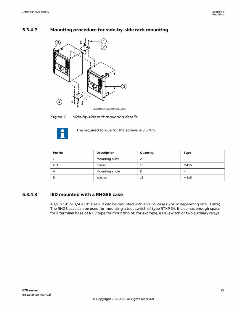
5.3.4.2 Mounting procedure for side-by-side rack mountingM11955-2 v4
IEC040004563enOriginal.vsdx
1
2
3
4
3
IEC04000456 V3 EN-US
Figure 7: Side-by-side rack mounting details.
The required torque for the screws is 3.5 Nm.
PosNo Description Quantity Type
1 Mounting plate 2 -
2, 3 Screw 16 M4x6
4 Mounting angle 2 -
5 Washer 16 M4x6
5.3.4.3 IED mounted with a RHGS6 caseM11953-3 v4
A 1/2 x 19” or 3/4 x 19” size IED can be mounted with a RHGS case (6 or 12 depending on IED size).The RHGS case can be used for mounting a test switch of type RTXP 24. It also has enough spacefor a terminal base of RX 2 type for mounting of, for example, a DC-switch or two auxiliary relays.
1MRK 514 026-UUS G Section 5Mounting
670 series 27Installation manual
© Copyright 2017 ABB. All rights reserved

8 88
7
5
6
3
4
2
7
5
6
7
5
6
3
4
2
3
4
2
1
1
2
1 1
1
8
7
5
6
3
4
2
2
1
IEC06000180-2-en.vsdIEC06000180 V2 EN-US
Figure 8: IED (1/2 x 19”) mounted with a RHGS6 case containing a test switch moduleequipped with only a test switch and a RX2 terminal base
5.3.5 Side-by-side flush mountingIP10329-1 v1
5.3.5.1 OverviewM11975-3 v3
If IP54 is required it is not allowed to flush mount side by side mounted cases. If your applicationdemands side-by-side flush mounting, the side-by-side mounting details kit and the 19” panel rackmounting kit must be used. The mounting kit has to be ordered separately. The maximum size ofthe panel cut out is 19”.
With side-by-side flush mounting installation, only IP class 20 is obtained. To reachIP class 54, it is required to mount the IEDs separately. For cut out dimensions ofseparately mounted IEDs, see section "Flush mounting".
Use only the screws included in the mounting kit when mounting the plates and theangles on the IED. Screws with wrong dimension may damage the PCBs inside theIED.
Please contact factory for special add on plates for mounting FT switches on theside (for 1/2 19" case) or bottom of the relay.
Section 5 1MRK 514 026-UUS GMounting
28 670 seriesInstallation manual
© Copyright 2017 ABB. All rights reserved

5.3.5.2 Mounting procedure for side-by-side flush mountingM12730-6 v4
1 2
3
4
IEC06000181-2-en.vsdIEC06000181 V2 EN-US
Figure 9: Side-by-side flush mounting details (RHGS6 side-by-side with 1/2 x 19” IED).
The required torque for the screws is 3.5 Nm.
PosNo Description Quantity Type
1 Mounting plate 2 -
2, 3 Screw, washer 16 M4x6
4 Mounting angle 2 -
5.3.6 Mounting the injection unit REX060 (REG670 only)GUID-264732AC-6C84-44E6-9F86-2065AD0B7D5B v3
The injection unit REX060 case size is 6U, 1/2 x 19”. REX060 can be rack, wall or flush mounted inthe same way as the IED. For guidance, see instructions for rack mounting, wall mounting or flushmounting the IED in this manual.
REX060 shall be mounted close to the IED. It is recommended that they are mounted in the samecubicle.
1MRK 514 026-UUS G Section 5Mounting
670 series 29Installation manual
© Copyright 2017 ABB. All rights reserved
5.3.7 Mounting the coupling capacitor unit REX061 and shunt resistorunit REX062 (REG670 only)
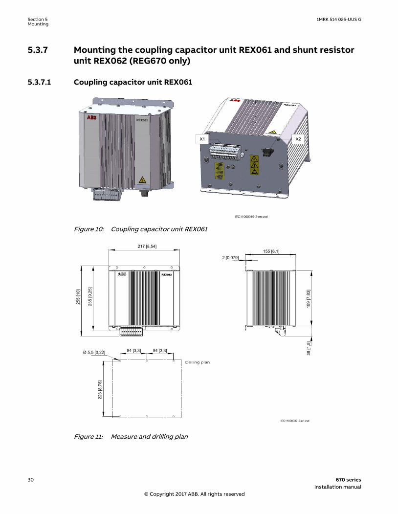
5.3.7.1 Coupling capacitor unit REX061GUID-59726B2B-0888-4CC1-8DEA-209F77CA5173 v5
X1 X2
IEC11000019-2-en.vsdIEC11000019 V1 EN-US
Figure 10: Coupling capacitor unit REX061
217 [8,54]
255
[10]
235
[9,2
5]
84 [3,3] 84 [3,3]Ø 5,5 [0,22]
223
[8,7
8]
2 [0,079]155 [6,1]
199
[7,8
3]38
[1,5
]
IEC11000037-2-en.vsd
IEC11000037 V2 EN-US
Figure 11: Measure and drilling plan
Section 5 1MRK 514 026-UUS GMounting
30 670 seriesInstallation manual
© Copyright 2017 ABB. All rights reserved

REX061 shall be mounted close to the generator in order to limit the exposure of the field circuit.Alternatively it can be located in the excitation cubicle.
The surface of REX061 unit may be temporarily very hot due to heat dissipation, upto about 50° C above the ambient temperature. It must be installed to get a openair convection and prevent contact with combustible material to the surface.
5.3.7.2 Shunt resistor unit REX062GUID-184D9033-33F3-4F85-8847-E9FDC95C3C41 v5
X1
IEC11000038-1-en.vsdIEC11000038 V1 EN-US
Figure 12: Shunt resistor unit REX062
1MRK 514 026-UUS G Section 5Mounting
670 series 31Installation manual
© Copyright 2017 ABB. All rights reserved

217 [8,54]
255
[10]
235
[9,2
5]
84 [3,3] 84 [3,3]Ø 5,5 [0,22]
223
[8,7
8]
2 [0,079]155 [6,1]
199
[7,8
3]38
[1,5
]
IEC11000039-2-en.vsd
IEC11000039 V2 EN-US
Figure 13: REX062 measures and drilling plan
REX062 shall be mounted close to the IED. It is recommended that REX060 and REX062 aremounted in the same cubicle as the IED.
The surface of REX062 unit may be temporarily very hot due to heat dissipation, upto about 65° C above the ambient temperature. It must be installed to get a openair convection and prevent contact with combustible material to the surface.
Section 5 1MRK 514 026-UUS GMounting
32 670 seriesInstallation manual
© Copyright 2017 ABB. All rights reserved

Section 6 Connecting
6.1 Making the electrical connection
6.1.1 IED connectorsSEMOD127536-1 v1
6.1.1.1 OverviewSEMOD129364-5 v1
The quantity and designation of connectors depend upon the type and size of the IED. The rearcover plates are prepared with space for the maximum of HW options for each case size and thecut-outs that are not in use are covered with a plate from factory.
OverviewM11562-3 v11
Table 2: Basic modules
Module Description
Power supply module (PSM) Including a regulated DC/DC converter that supplies auxiliaryvoltage to all static circuits.
• An internal fail alarm output is available.
Numerical module (NUM) Module for overall application control. All information isprocessed or passed through this module, such as configuration,settings and communication. The module provides four SFPs forEthernet traffic.
Local Human machine interface (LHMI) The module consists of LEDs, an LCD, a push button keyboard andan ethernet connector used to connect a PC to the IED.
Transformer input module (TRM) Transformer module that galvanically separates the internalcircuits from the VT and CT circuits. It has 12 analog inputs.
Analog digital conversion module (ADM) The module converts the VT and CT analog signals from the TRMto digital signals processed by the NUM. Carrier forcommunication boards.Note: TRM module is not included in SAM600-IO, so ADM moduleis only used for internal communication carrier for IO modules.
Combined backplane module (CBM) The module has two main purposes: to distribute supply voltagesfrom the PSM to the other modules and to act as acommunication carrier via its two buses, CompactPCI for fast I/Oand communication and CAN for slow I/O.
Universal backplane module (UBM) The module is used to interconnect the TRM and the ADM. It alsoconnects the NUM with the LHMI
1MRK 514 026-UUS G Section 6Connecting
670 series 33Installation manual
© Copyright 2017 ABB. All rights reserved

Table 3: Application specific modules
Module Description
Binary input module (BIM) Module with 16 optically isolated binary inputs
Binary output module (BOM) Module with 24 single outputs or 12 double-pole commandoutputs including supervision function
Binary I/O module (IOM) Module with 8 optically isolated binary inputs, 10 outputs and 2fast signalling outputs.
Line data communication modules (LDCM),short range, medium rang, long range
Modules used for digital communication to remote terminal.
Serial SPA/LON/IEC 60870-5-103communication modules (SLM)
Used for SPA/LON/DNP3/IEC 60870–5–103 communication.
Optical Ethernet module (OEM) Module used for Ethernet traffic. It has support for two SFPs.
Optical Ethernet SFP Small form factor pluggable for Ethernet communication
Galvanic RJ45 Ethernet SFP Small form factor pluggable for Ethernet communication
mA input module (MIM) Analog input module with 6 independent, galvanically separatedchannels
GPS time synchronization module (GTM) Used to provide the IED with GPS time synchronization and pulseper second (PPS) output
Static output module (SOM) Module with 6 fast static outputs and 6 change over output relays
IRIG-B Time synchronization module (IRIG-B) Module with 2 inputs. One is used for handling both pulse-widthmodulated signals and amplitude modulated signals and one isused for optical input type ST for PPS time synchronization.
Section 6 1MRK 514 026-UUS GConnecting
34 670 seriesInstallation manual
© Copyright 2017 ABB. All rights reserved

6.1.1.2 Front side connectorsSEMOD129384-5 v3
1
2
ANSI16000051.vsdx
ANSI16000051 V1 EN-US
Figure 15: RJ-45 communication port
1 IED service port with RJ-45 connector
2 Green indicator LED (lit when the cable is successfully connected)
1MRK 514 026-UUS G Section 6Connecting
670 series 35Installation manual
© Copyright 2017 ABB. All rights reserved

6.1.1.3 Rear side connectorsSEMOD129387-1 v1
M16105-3 v10
Table 4: Designations for 1/2 x 19” casing with 1 TRM slot
1MRK002801-AC-2-670-1.2-PG V.3 EN1MRK002801-AC-2-670-1.2-PG V4 EN-US
Rear position Module
X11 PSM
X31 and X32 etc. to X51 and X52 BIM, BOM, SOM, IOM or MIM
X301, X302, X303, X304 SFP
X305 LDCM
X306 LDCM or OEM
X3061, X3062 SFP if OEM is selected
X311: A, B, C, D SLM
X312 LDCM, IRIG-B, GTM
X313 LDCM, IRIG-B, GTM, RS485
X401 TRM
Section 6 1MRK 514 026-UUS GConnecting
36 670 seriesInstallation manual
© Copyright 2017 ABB. All rights reserved

SEMOD111882-4 v8
Table 5: Designations for 3/4 x 19” casing with 1 TRM slot
1MRK002801-AC-3-670-1.2-PG V4 EN-US
Rear position Module
X11 PSM
X31 and X32 etc. to X101 and X102 BIM, BOM, SOM, IOM or MIM
X301, X302, X303, X304 SFP
X305 LDCM
X306 LDCM
X3061, X3062 SFP if OEM is selected
X311: A, B, C, D SLM
X312 LDCM, IRIG-B, GTM
X313 LDCM, IRIG-B, GTM, RS485
X401 TRM
1MRK 514 026-UUS G Section 6Connecting
670 series 37Installation manual
© Copyright 2017 ABB. All rights reserved

SEMOD111884-4 v7
Table 6: Designations for 3/4 x 19” casing with 2 TRM slot
1MRK002801-AC-4-670-1.2-PG V.3 EN1MRK002801-AC-4-670-1.2-PG V4 EN-US
Rear position Module
X11 PSM
X31 and X32 etc. to X71 and X72 BIM, BOM, SOM, IOM or MIM
X301. X302, X303, X304 SFP
X305 LDCM
X306 LDCM
X3061, X3062 SFP if OEM is selected
X311: A, B, C, D SLM
X312 LDCM, IRIG-B, GTM
X313, X322, X323 LDCM, IRIG-B, GTM, RS485
X401 TRM 1
X411 TRM 2
Section 6 1MRK 514 026-UUS GConnecting
38 670 seriesInstallation manual
© Copyright 2017 ABB. All rights reserved

M16106-3 v10
Table 7: Designations for 1/1 x 19” casing with 1 TRM slot
1MRK002801-AC-5-670-1.2-PG V.3 EN1MRK002801-AC-5-670-1.2-PG V4 EN-US
Rear position Module
X11 PSM
X31 and X32 etc. to X161and X162
BIM, BOM, SOM, IOM orMIM
X301, X302, X303, X304 SFP
X305 LDCM
X306 LDCM
X3061, X3062 SFP if OEM is selected
X311: A, B, C, D SLM
X312 LDCM, IRIG-B, GTM
X313 LDCM, IRIG-B, GTM,RS485
X401 TRM
1MRK 514 026-UUS G Section 6Connecting
670 series 39Installation manual
© Copyright 2017 ABB. All rights reserved

M16108-3 v10
Table 8: Designations for 1/1 x 19” casing with 2 TRM slots
1MRK002801-AC-6-670-1.2-PG V.3 EN1MRK002801-AC-6-670-1.2-PG V4 EN-US
Rear position Module
X11 PSM
X31 and X32 etc. to X131and X132
BIM, BOM, SOM, IOM orMIM
X301, X302, X303, X304 SFP
X305 LDCM
X306 LDCM
X3061, X3062 SFP if OEM is selected
X311: A, B, C, D SLM
X312 LDCM, IRIG-B, GTM
X313, X322, X323 LDCM, IRIG-B, GTM,RS485
X401 TRM 1
X411 TRM 2
Section 6 1MRK 514 026-UUS GConnecting
40 670 seriesInstallation manual
© Copyright 2017 ABB. All rights reserved
SEMOD53217-4 v14
ANSI08000479 V1 EN-US
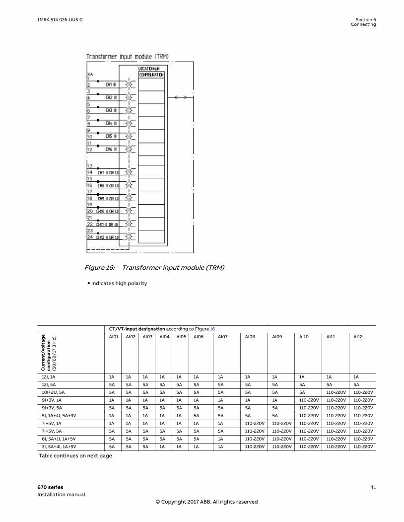
Figure 16: Transformer input module (TRM)
■ Indicates high polarity
CT/VT-input designation according to Figure 16
Cur
rent
/vol
tage
conf
igur
atio
n(5
0/6
0/1
7.3
Hz) AI01 AI02 AI03 AI04 AI05 AI06 AI07 AI08 AI09 AI10 AI11 AI12
12I, 1A 1A 1A 1A 1A 1A 1A 1A 1A 1A 1A 1A 1A
12I, 5A 5A 5A 5A 5A 5A 5A 5A 5A 5A 5A 5A 5A
10I+2U, 5A 5A 5A 5A 5A 5A 5A 5A 5A 5A 5A 110-220V 110-220V
9I+3V, 1A 1A 1A 1A 1A 1A 1A 1A 1A 1A 110-220V 110-220V 110-220V
9I+3V, 5A 5A 5A 5A 5A 5A 5A 5A 5A 5A 110-220V 110-220V 110-220V
5I, 1A+4I, 5A+3V 1A 1A 1A 1A 1A 5A 5A 5A 5A 110-220V 110-220V 110-220V
7I+5V, 1A 1A 1A 1A 1A 1A 1A 1A 110-220V 110-220V 110-220V 110-220V 110-220V
7I+5V, 5A 5A 5A 5A 5A 5A 5A 5A 110-220V 110-220V 110-220V 110-220V 110-220V
6I, 5A+1I, 1A+5V 5A 5A 5A 5A 5A 5A 1A 110-220V 110-220V 110-220V 110-220V 110-220V
3I, 5A+4I, 1A+5V 5A 5A 5A 1A 1A 1A 1A 110-220V 110-220V 110-220V 110-220V 110-220V
Table continues on next page
1MRK 514 026-UUS G Section 6Connecting
670 series 41Installation manual
© Copyright 2017 ABB. All rights reserved

3IM, 1A+4IP, 1A+5V 1AM*)
1AM*)
1AM*)
1A 1A 1A 1A 110-220V 110-220V 110-220V 110-220V 110-220V
3IM, 5A+4IP, 5A+5V 5AM*)
5AM*)
5AM*)
5A 5A 5A 5A 110-220V 110-220V 110-220V 110-220V 110-220V
6I+6V, 1A 1A 1A 1A 1A 1A 1A 110-220V 110-220V 110-220V 110-220V 110-220V 110-220V
6I+6V, 5A 5A 5A 5A 5A 5A 5A 110-220V 110-220V 110-220V 110-220V 110-220V 110-220V
3I, 5A+3I, 1A+6V 5 A 5 A 5 A 1A 1A 1A 110-220V 110-220V 110-220V 110-220V 110-220V 110-220V
6I, 1A 1A 1A 1A 1A 1A 1A - - - - - -
6I, 5A 5A 5A 5A 5A 5A 5A - - - - - -
*) Metering
Note that internal polarity can be adjusted by setting of analog input CT neutral direction and/or on SMAI pre-processing functionblocks.
Section 6 1MRK 514 026-UUS GConnecting
42 670 seriesInstallation manual
© Copyright 2017 ABB. All rights reserved

1MRK002801-AC-11-670-1.2-PG V2 EN-US
Figure 17: Binary input module (BIM)
1MRK 514 026-UUS G Section 6Connecting
670 series 43Installation manual
© Copyright 2017 ABB. All rights reserved

XA7
89
13
1415
1617
18
1011
12
mA input module (MIM)
CH1
CH2
CH3
CH4
CH5
CH6
CONFIGURATION
LOCATION=pN
1MRK002801-AC-15-670-1.2-PG V2 EN-US
Figure 18: mA input module (MIM)
1MRK002801-AC-8-670-1.2-PG V3 EN-US
Figure 19: IED with basic functionality and communication interfaces
Section 6 1MRK 514 026-UUS GConnecting
44 670 seriesInstallation manual
© Copyright 2017 ABB. All rights reserved

X1113
X11
2 X11
4 5
Power supply module (PSM)
INTERNAL FAIL
p1
+ -
ReadyFail
+ Protective earth must be connected
EL1MRK002801-AC-7-670-1.2-PG V3 EN-US
Figure 20: Power supply module (PSM)
1MRK002801-AC-12-670-1.2-PG V1 EN-US
Figure 21: Binary output module (BOM)
1MRK 514 026-UUS G Section 6Connecting
670 series 45Installation manual
© Copyright 2017 ABB. All rights reserved

1MRK002801-AC-13-670-1.2-PG V2 EN-US
Figure 22: Static output module (SOM)
1MRK002801-AC-14-670-1.2-PG V2 EN-US
Figure 23: Binary in/out module (IOM)
Section 6 1MRK 514 026-UUS GConnecting
46 670 seriesInstallation manual
© Copyright 2017 ABB. All rights reserved

6.1.1.4 Connection examples for high impedance differential protectionGUID-8C58A73D-7C2E-4BE5-AB87-B4C93FB7D62B v5
WARNING! USE EXTREME CAUTION! Dangerously high voltages might be presenton this equipment, especially on the plate with resistors. De-energize the primaryobject protected with this equipment before connecting or disconnecting wiring orperforming any maintenance. The plate with resistors should be provided with aprotective cover, mounted in a separate box or in a locked cubicle. National law andstandards shall be followed.
Connections for three-phase high impedance differential protectionGUID-C12CCAAF-5AE5-4A9C-AC9C-F56A66FD2C14 v8
Generator, reactor or busbar differential protection is a typical application for three-phase highimpedance differential protection. Typical CT connections for three-phase high impedancedifferential protection scheme are shown in figure 24.
L1
(A)
L2
(B)
L3
(C)
Protected Object
CT 1200/1
Star/Wye
Connected
L1
(A)
L2
(B)
L3
(C)
CT 1200/1
Star/Wye
Connected
7
8
91
01
11
2
1
2
3
4
5
6
AI01
(I)
AI02
(I)
AI03
(I)
AI04
(I)
AI05
(I)
AI06
(I)
7
6
X1
R4
R5
R6
12
12
12
11 12 13 14
U U U R1
13
4
2
13
R2
2
4
13
R3
2
4
1 2 3 4 5 6 7
L1 (A)
L2 (B)
L3 (C)
N
3-Ph Plate with Metrosils and Resistors
2
3
5
4
X X
L1 (A)
L2 (B)
L3 (C)
N
1
IED
SMAI2
BLOCK
REVROT
^GRP2_A
^GRP2_B
^GRP2_C
^GRP2_N
G2AI3P
G2AI1
G2AI2
G2AI3
G2AI4
G2N
ANSI09000169-4-en.vsdx
ANSI09000169 V4 EN-US
Figure 24: CT connections for high impedance differential protection
Pos Description
1 Scheme grounding point
It is important to insure that only one grounding point exist in this scheme.
2 Three-phase plate with setting resistors and metrosils. Protective ground is a separate 4 mm screwterminal on the plate.
3 Necessary connection for three-phase metrosil set.
1MRK 514 026-UUS G Section 6Connecting
670 series 47Installation manual
© Copyright 2017 ABB. All rights reserved

4 Position of optional test switch for secondary injection into the high impedance differential IED.
5 Necessary connection for setting resistors.
6 Factory-made star point on a three-phase setting resistor set.
The star point connector must be removed for installations with 670 series IEDs. Thisstar point is required for RADHA schemes only.
7 Connections of three individual phase currents for high impedance scheme to three CT inputs in the IED.
Connections for 1Ph High impedance differential protection HZPDIF (87)GUID-D68A237F-610C-4AF0-870F-273117F64D92 v10
Restricted earth fault protection is a typical application for 1Ph High impedance differentialprotection HZPDIF (87). Typical CT connections for the high impedance based protection schemeare shown in figure 25.
L1
(A)
L2
(B)
L3
(C)
Protected Object
CT 1500/5
Star/Wye
Connected
7
8
9
10
11
12
1
2
3
4
5
6
AI01 (I)
AI02 (I)
AI03 (I)
AI04 (I)
AI05 (I)
AI06 (I)
6
IED
X1
R1
12
4 5
V R2
13
4
2
1 2 3
N
1-Ph Plate with Metrosil and Resistor
2
3
5
4
N
L1
(A)
L2
(B)
L3
(C)
CT
15
00
/5
1
ANSI09000170-5-en.vsdx
SMAI2
BLOCK
REVROT
^GRP2_A
^GRP2_B
^GRP2_C
^GRP2_N
G2AI3P
G2AI1
G2AI2
G2AI3
G2AI4
G2N
ANSI09000170 V5 EN-US
Figure 25: CT connections for restricted earth fault protection
Pos Description
1 Scheme grounding point
Ensure that only one grounding point exists in this scheme.
2 One-phase plate with stabilizing resistor and metrosil. Protective ground is a separate 4 mm screwterminal on the plate.
3 Necessary connection for the metrosil.
Section 6 1MRK 514 026-UUS GConnecting
48 670 seriesInstallation manual
© Copyright 2017 ABB. All rights reserved
4 Position of optional test switch for secondary injection into the high impedance differential IED.
5 Necessary connection for stabilizing resistor.
6 How to connect the high impedance restricted earth fault protection scheme to one CT input in IED.
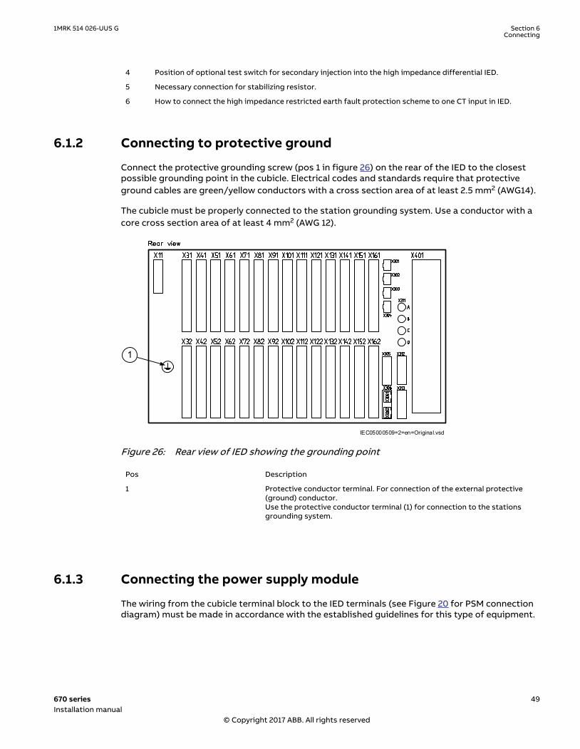
6.1.2 Connecting to protective groundM11997-4 v11
Connect the protective grounding screw (pos 1 in figure 26) on the rear of the IED to the closestpossible grounding point in the cubicle. Electrical codes and standards require that protectiveground cables are green/yellow conductors with a cross section area of at least 2.5 mm2 (AWG14).
The cubicle must be properly connected to the station grounding system. Use a conductor with acore cross section area of at least 4 mm2 (AWG 12).
IEC05000509=2=en=Original.vsd
1
IEC05000509 V2 EN-US
Figure 26: Rear view of IED showing the grounding point
Pos Description
1 Protective conductor terminal. For connection of the external protective(ground) conductor.Use the protective conductor terminal (1) for connection to the stationsgrounding system.
6.1.3 Connecting the power supply moduleSEMOD128790-5 v7
The wiring from the cubicle terminal block to the IED terminals (see Figure 20 for PSM connectiondiagram) must be made in accordance with the established guidelines for this type of equipment.
1MRK 514 026-UUS G Section 6Connecting
670 series 49Installation manual
© Copyright 2017 ABB. All rights reserved

Insert only the corresponding male connector to the female connector. Insertinganything else (such as a measurement probe) may violate the female connectorand prevent a proper electrical contact between the printed circuit board and theexternal wiring connected to the screw terminal block.
The auxiliary power wiring should have a minimum cross-sectional area of 1.0 mm2 and a voltagerating of 250 V. Branch circuit protection must be provided in the auxiliary power supply wiring tothe IED, and if necessary it must be possible to disconnect manually from the power supply. Fuseor circuit breaker up to 6 A and 250 V should be close to the equipment. It is recommended toseparate the instrument transformer leads from the other cables, that is, they should not be run inthe same cable ducts or loom. The connections are made on connector X11.
6.1.4 Connecting to CT and VT circuitsM11991-6 v3
CTs and VTs are connected to the 24–pole connector of the Transformer input module (TRM) onthe rear side of the IED. Connection diagram for TRM is shown in figure 16.
Use a solid conductor with a cross section area between 2.5-6 mm2 (AWG14-10) or a strandedconductor with a cross section area between 2.5-4 mm2 (AWG14-12).
If the IED is equipped with a test-switch of type RTXP 24, COMBIFLEX wires with 20 A socketsmust be used to connect the CT and VT circuits.
M11991-10 v4
Connectors on TRM (for location see section "Rear side connectors") for current and voltagetransformer circuits are so called “feed-through IED blocks” and are designed for conductors withcross sectional area up to 4 mm2 (AWG 12). The screws used to fasten the conductors should betightened with a torque of 1Nm.
Connector terminals for CT and VT circuits, as well as terminals for binary input and outputsignals, can be of either ringlug or compression connection type, depending on ANSI/IECstandards, or customers choice.
Section 6 1MRK 514 026-UUS GConnecting
50 670 seriesInstallation manual
© Copyright 2017 ABB. All rights reserved

IEC06000505 V1 EN-US
Figure 27: Examples of ringlugterminals
IEC06000506 V1 EN-US
Figure 28: Examples of standardcompression connectionterminals
SEMOD53376-2 v6
Table 9: CT and VT circuit connectors
Connector type Rated voltage and current Maximum conductor area
Screw compression type 250 V AC, 20 A 4 mm2 (AWG12)2 x 2.5 mm2 (2 x AWG14)
Terminal blocks suitable for ring lug terminals 250 V AC, 20 A 4 mm2 (AWG12)
6.1.5 Connecting the binary input and output signalsM11992-9 v8
Auxiliary power and signals are connected using voltage connectors. Signal wires are connected toa female connector (see Figure 29) which is then plugged into the corresponding male connector(see Figure 30) located at the rear of the IED. For location of BIM, BOM, SOM and IOM refer tosection "Rear side connectors". Connection diagrams for BIM, BOM, SOM and IOM are shown inFigure 17, Figure 21, Figure 22 and Figure 23.
Do not insert anything else to the female connector but the corresponding maleconnector. Inserting anything else (such as a measurement probe) may violate thefemale connector and prevent a proper electrical contact between the printedcircuit board and the external wiring connected to the screw terminal block.
If the IED is equipped with a test-switch of type RTXP 24, COMBIFLEX wires with 20 A sockets,1.5mm² (AWG16) conductor area must be used to connect the auxiliary power.
1MRK 514 026-UUS G Section 6Connecting
670 series 51Installation manual
© Copyright 2017 ABB. All rights reserved

Procedure
1. Connect signals to the female connectorThe conductors can be of rigid type (solid, stranded) or of flexible type.The female connectors accept conductors with a cross section area of 0.2-2.5 mm2 (AWG24-14). If two conductors are used in the same terminal, the maximum permissible crosssection area is 0.2-1 mm2 (AWG 24-18).If two conductors, each with area 1.5 mm2 (AWG 16) need to be connected to the sameterminal, a ferrule must be used, see figure 31. Crimp this ferrule properly to the wire usingtools as recommended by the supplier of the ferrules (keep stripping length of the cable tominimum 10 mm). The fastening screw shall be tightened with a torque of 0.4 Nm (Thistorque applies to all binary connectors).
2. Plug the female connector to the corresponding back-side mounted male connector3. Lock the female connector by fastening the lock screws
IEC02000742-2-en.vsdx
IEC02000742 V2 EN-US
IEC16000050-1-en.vsdx
IEC16000050 V1 EN-US
Figure 29: A female connector (top: screw compression type, bottom: ringlug type)
IEC04000167 V1 EN-US
Figure 30: Board with male connectors
Section 6 1MRK 514 026-UUS GConnecting
52 670 seriesInstallation manual
© Copyright 2017 ABB. All rights reserved

12
IEC06000168 V3 EN-US
Figure 31: Accessories
PosNo Description
1 Ferrule
2 Bridge connector, used to jump terminal points in a connector.
M12583-1 v8
Table 10: Auxiliary power supply and binary I/O connectors
Connector type Rated voltage Maximum conductor area
Screw compression type 250 V AC 2.5 mm2 (AWG14)2 × 1 mm2 (2 x AWG18)
Terminal blocks suitable for ring lug terminals 300 V AC 3 mm2 (AWG14)
Because of limitations of space, when ring lug terminal is ordered for Binary I/Oconnections, one blank slot is necessary between two adjacent I/O modules. Pleaserefer to the ordering particulars for details.
6.1.6 Making the shield connectionM11998-3 v6
When using shielded cables, always make sure that the shields are connected according toapplicable engineering methods.
1MRK 514 026-UUS G Section 6Connecting
670 series 53Installation manual
© Copyright 2017 ABB. All rights reserved

For RS485 only: at the IED end, always connect the shield to the IED with the shieldconnection clamp, shown below.
IEC13000234-1-en.vsdGUID-682A59D0-950C-4D89-8318-984E0A8B2761 V1 EN-US
Figure 32: Shield connection clamp
The cable shield shall be properly connected to the IED chassis by the cable clampwith the maximum open conductor length of 1.57” between clamp and terminals. Ifdouble shielded cable is used, the inner cable shielding should be connected at theexternal equipment end only. At the IED terminal end, the inner shield should beisolated.
Section 6 1MRK 514 026-UUS GConnecting
54 670 seriesInstallation manual
© Copyright 2017 ABB. All rights reserved

6.2 Making the electrical connection to the rotor and statorinjection equipment (REG670 only)
6.2.1 Connectors for injection unit REX060, coupling capacitor unitREX061 and shunt resistor unit REX062
6.2.1.1 Injection unit REX060GUID-18B7451E-7F72-4C24-99E7-E72ED2F99B43 v3
X11
Rear view
X61 X81
X62 X82
1/2x19" (241.3 mm)
6U(266.7 mm)
X81 p8 p6 p1
Front view
HLM
Module Slot TerminalPSMSIMRIM p8
p6p1 X11
X61, X62X81, X82
1MRK002501-BA-2-PG V2 EN-US
Figure 33: Designation for REX060 unit casing
Protective conductor terminal. For connection of the external protective (earth) conductor.
1MRK002501-BA-3-PG V2 EN-US
Figure 34: Power supply module
1MRK 514 026-UUS G Section 6Connecting
670 series 55Installation manual
© Copyright 2017 ABB. All rights reserved

1MRK002501-BA-4-PG V3 EN-US
Figure 35: Stator injection module
1MRK002501-BA-5-PG V3 EN-US
Figure 36: Rotor injection module
Section 6 1MRK 514 026-UUS GConnecting
56 670 seriesInstallation manual
© Copyright 2017 ABB. All rights reserved

6.2.1.2 Coupling capacitor unit REX061GUID-A35479A3-6BE6-4C8A-BE3C-FF03AF68A197 v2
Front view
Bottom view
X1 X2
ABB
(235 mm)
(217 mm)
Module Slot TerminalCCM P1 X1, X2
REX061
P1
1MRK002551-BA-1-PG V2 EN-US
Figure 37: Designation for capacitor unit casing
Protective conductor terminal. For connection of the external protective (earth) conductor.
1MRK 514 026-UUS G Section 6Connecting
670 series 57Installation manual
© Copyright 2017 ABB. All rights reserved

1MRK002551-BA-2-PG V2 EN-US
Figure 38: Coupling capacitor module
Section 6 1MRK 514 026-UUS GConnecting
58 670 seriesInstallation manual
© Copyright 2017 ABB. All rights reserved

6.2.1.3 Shunt resistor unit REX062GUID-F16BA87E-7744-4236-BC98-4EBB3FF576A9 v2
Front view
Bottom view
X1
ABB
(235 mm)
(217 mm)
P1
Module Slot TerminalSRM P1 X1
REX062
1MRK002556-BA-1-PG V2 EN-US
Figure 39: Designation for shunt resistor unit casing
Protective conductor terminal. For connection of the external protective (earth) conductor.
1MRK 514 026-UUS G Section 6Connecting
670 series 59Installation manual
© Copyright 2017 ABB. All rights reserved

1MRK002556-BA-2-PG V2 EN-US
Figure 40: Shunt resistor module
6.2.2 Connecting injection unit REX060, coupling capacitor unitREX061 and shunt resistor unit REX062
GUID-0B6A1CDE-9CDE-413C-9E85-9314175D901E v4
The injection unit REX060 should be installed close to the IED in the same cubicle, or at minimumwithin 10 m distance of the IED.
The coupling capacitor unit REX061 should be mounted close to the generator in order to limit theexposure of the field circuit. Alternatively it can be located in the excitation cubicle. REX061 shouldbe connected as a permanently connected equipment. The connection cables should be at least 1.5mm2 (16 AWG) at rated rotor injection voltage 250 V and rated field injection voltage 800 VDC.
The shunt resistor unit REX062, if used in the application, should preferably also be installed in thesame cubicle as REX060.
For information on type, cross section and maximum length of the cables refer tosection Connection diagrams in the REG 670 Technical Manual.
Connecting to protective ground
Connect the protective grounding screw on the rear of each unit to the closest possible groundingpoint in the cubicle. Electrical codes and standards require that protective ground cables aregreen/yellow conductors with a cross section area of at least 2.5 mm2 (AWG 14).
The cubicle must be properly connected to the station grounding system. Use a conductor with acore cross section area of at least 4 mm2 (AWG 12).
Connecting the power supply module
The wiring from the cubicle terminal block to the REX060 unit (see figure 34 for PSM connectiondiagram) must be made in accordance with the established guidelines for this type of equipment.The auxiliary power wiring should have a minimum cross-sectional area of 1.0 mm2 and a voltagerating of 250 V. Branch circuit protection must be provided in the auxiliary power supply wiring tothe IED and, if necessary, it must be possible to disconnect it manually from the power supply.Fuse or circuit breaker up to 6 A and 250 V should be close to the equipment. It is recommended to
Section 6 1MRK 514 026-UUS GConnecting
60 670 seriesInstallation manual
© Copyright 2017 ABB. All rights reserved

separate the instrument transformer leads from the other cables, that is, they should not be run inthe same cable ducts or loom.
Connection examples
The figures below show typical installations for rotor and stator ground fault protection withinjection unit REX060 and coupling capacitor unit REX061. Some installations with and withoutshunt resistor unit REX062 are also shown.
IEC11000224-3-en.vsdx
IEC11000224 V3 EN-US
Figure 41: Rotor connection example
IEC11000225-2-en.vsd
IEC11000225 V3 EN-US
Figure 42: Stator connection example, with REX062
1MRK 514 026-UUS G Section 6Connecting
670 series 61Installation manual
© Copyright 2017 ABB. All rights reserved

IEC11000236-2-en.vsd
IEC11000236 V3 EN-US
Figure 43: Stator connection example, without REX062
For connection details regarding REX060, REX061 and REX062, refer to section Connectiondiagrams in the REG670 Technical Manual.
REX060 connections
Table 11: Power X11
No Signal
1 Ready, Power off NO binary out
2 Power off common binary out
3 Fail, Power off NC binary out
4 Power input positive
5 Power input negative
Table 12: Stator IED and sense connection X61
No Signals
1 Block injection, 220 V binary in
2 Block injection, 110 V binary in
3 Block injection, 48 V binary in
4 Block injection, Common binary in
5 Injection Blocked NC binary out
6 Voltage/Current Saturation NO binary out
7 Common binary out
8 Voltage A, analog out
Table continues on next page
Section 6 1MRK 514 026-UUS GConnecting
62 670 seriesInstallation manual
© Copyright 2017 ABB. All rights reserved

No Signals
9 Voltage B analog out
10 Current A analog out
11 Current B analog out
12 Voltage sense A
13 Voltage sense B
14 Current sense A (same as 16)
15 Current sense B
16 Current sense A (same as 14)
17 -
18 -
Table 13: Stator injection connection X62
No Signal
1 Injection, via extern shunt resistor
2 Injection return, via extern shunt resistor
3 Injection
4 Injection return (same as 5)
5 Injection return (same as 4)
Table 14: Rotor injection and IED connection X81
No Signal
1 Block injection, 220 V binary in
2 Block injection, 110 V binary in
3 Block injection, 48 V binary in
4 Block injection, Common binary in
5 Injection Blocked NC binary out
6 Voltage/Current Saturation NO binary out
7 Common binary out
8 Voltage A, analog out
9 Voltage B analog out
10 Current A analog out
11 Current B analog out
12 Voltage sense A
13 Voltage sense B
14 Current sense A (same as 16)
15 Current sense B
16 Current sense A (same as 14)
17 -
18 -
1MRK 514 026-UUS G Section 6Connecting
670 series 63Installation manual
© Copyright 2017 ABB. All rights reserved

Table 15: Rotor injection connection X82
No Signal
1 Injection (same as 3)
2 Injection, inside shunt resistor
3 Injection (same as 1)
4 Injection return (same as 5)
5 Injection return (same as 4)
Connect each signal connector terminal of screw compression type with one 0.5 to 2.5 mm2 (AWG24 - AWG 14) wire or with two 0.5 to 1.0 mm2 (AWG 24 - AWG 18) wires.
Protective conductor terminal must be connected to the cubicle or station protective groundingsystem. Electrical codes and standards require that protective ground cables are green/yellowconductors with a cross section area of at least 2.5 mm2 (AWG 14). The cubicle must be properlyconnected to the station grounding system. Use a conductor with a core cross section area of atleast 4 mm2 (AWG 12).
REX061 Capacitor unit connections
Table 16: Injection and rotor connection X1
No Signal
1 Rotor positive pole
2 -
3 Positive pole
4 -
5 Negative pole
6 -
7 Rotor negative pole
8 -
9 Rotor injection
10 Injection ground. Internally connected to chassis and PE
Table 17: Measurment connector X2
No Signal
1 Rotor + voltage divided by 1 000
2 Ground
3 Rotor - voltage divided by 1 000
X1 connector. Connect each signal connector terminal of screw compression type with one 0.14 to6 mm2 (AWG 35 - AWG 3) wire or with two 0.14 to 1.5 mm2 (AWG 35 - AWG 15) wires.
Section 6 1MRK 514 026-UUS GConnecting
64 670 seriesInstallation manual
© Copyright 2017 ABB. All rights reserved

X2 connector. Connect each signal connector terminal of screw compression type with one 0.5 to2.5 mm2 (AWG 24 - AWG 14) wire or with two 0.5 to 1.0 mm2 (AWG 24 - AWG 18) wires.
Protective conductor terminal must be connected to the cubicle or station protective groundingsystem. Electrical codes and standards require that protective ground cables are green/yellowconductors with a cross section area of at least 2.5 mm2 (AWG 14). The cubicle must be properlyconnected to the station grounding system. Use a conductor with a core cross section area of atleast 4 mm2 (AWG 12).
The protective grounding terminal is also the functional ground terminal. The functional ground isthe reference for rotor injection and measurement. The connection to the generator grounding,and also to the station, should be as short and low impedance as possible to reduce unwanteddisturbances and improve the quality of rotor measurements.
REX062 Shunt resistor unit connections
Table 18: Injection via shunt resistors connection X1
No Signal
1 -
2 Injection
3 -
4 Injection return
5 -
6 Current sense output
7 -
8 Current sense output
9 Injection input, External shunt
10 Injection input return, External shunt
X1 connector. Connect each signal connector terminal of screw compression type with one 0.14 to6 mm2 (AWG 35 - AWG 3) wire or with two 0.14 to 1.5 mm2 (AWG 35 - AWG 15) wires.
Protective conductor terminal must be connected to the cubicle or station protective groundingsystem. Electrical codes and standards require that protective ground cables are green/yellowconductors with a cross section area of at least 2.5 mm2 (AWG 14). The cubicle must be properlyconnected to the station grounding system. Use a conductor with a core cross section area of atleast 4 mm2 (AWG 12).
6.2.3 Connecting and setting voltage inputsGUID-BE3E0554-3E96-4489-B8C9-E62953853BB7 v4
The RIM module of REX060 has two analog output channels that shall be connected to two voltageinput channels of the IED.
If both stator and rotor protection are used, there are two possible methods to perform theconnection.
1MRK 514 026-UUS G Section 6Connecting
670 series 65Installation manual
© Copyright 2017 ABB. All rights reserved

1. The recommended connection require four analog channels of the IED: two IED voltagechannels are used for the measured quantities for ROTIPHIZ; two more IED voltage channelsare used for the measured quantities for STTIPHIZ.
REX060X61
9
8
8
9
11
10
11
10
X81
STATOR MODULE SIM
ROTOR MODULE RIM
IED
VOLTAGE MEASURE (V)
VOLTAGE MEASURE (V)
CURRENT MEASURE (V)
CURRENT MEASURE (V)
ANSI11000209_1_en.vsdANSI11000209 V1 EN-US
Figure 44: Separate analog inputs for stator STTIPHIZ (64S) and rotor ROTIPHIZ (64R)protection
2. It is possible to use a mixed connection that requires only two IED voltage channels for bothROTIPHIZ and STTIPHIZ. REX060 outputs are connected in series. This connection is notrecommended and can be used only in applications where it is prove the possibility to use it.the use of this connection leads to reduced performances of both ROTIPHIZ and STTIPHIZ.
REX060X61
9
8
8
9
11
10
11
10
X81
STATOR MODULE SIM
ROTOR MODULE RIM
IED
VOLTAGE MEASURE (V)
CURRENT MEASURE (V)
ANSI11000210_1_en.vsdANSI11000210 V1 EN-US
Figure 45: Connection to IED with two analogue voltage inputs
Section 6 1MRK 514 026-UUS GConnecting
66 670 seriesInstallation manual
© Copyright 2017 ABB. All rights reserved

Some settings are required for the analog voltage inputs. Set the voltage ratio for the inputs to1/1, for example, VTSecx = 100 V VTPrimx = 0.1 kV
The analog inputs are linked to a pre-processor block in the Signal Matrix Tool. This pre-processorblock must have the same cycle time, 8 ms, as the function blocks for STTIPHIZ (64S) andROTIPHIZ (64R).
The default parameter settings are used for the pre-processor block.
It is possible to connect two REG670 IEDs in parallel to the REX060 injection unit in order to obtainredundant measurement in the two IEDs. However, at commissioning, both IEDs must beconnected during the calibration procedure.
It is important that REX060, REX061 and REX062 chassis are solidly grounded.Protective ground is a separate 0.15” screw terminal that is a part of the metallicchassis.
Avoid touching the enclosure of the coupling capacitor REX061 unit and the shuntresistor REX062 unit. The surface may be hot during normal operation. Thetemperature can rise 50°C in REX061 and 65°C in REX062 above the ambienttemperature.
6.3 Making of Ethernet connections
6.3.1 Connecting station communication interfacesM11720-2 v11
The numerical module (NUM) provides up to four Ethernet ports (one basic and three optional),and the optical Ethernet module (OEM) provides two additional Ethernet ports. These ports areused for IEC 61850 or DNP3 communication. The serial communication module (SLM) providesfour optical ports which are used for LON, SPA, IEC 60870-5-103 or DNP3 communication.
• Ports X301 to X304 on the NUM module and ports X3061 and X3062 on the OEM module areused for IEC 61850-8-1 and IEC/UCA 61850-9-2LE communication. Ports X301/X302, X303/X304 and X3061/X3062 are to be used in pairs for redundant communication. The optical portconnectors are of LC type and the galvanic connectors are of RJ45 type.
• Optical ports X311 A and B on the SLM module are used for SPA, IEC 60870-5-103 or DNP3communication. The port connectors are of ST (glass) or HFBR Snap in (plastic) type.
• Optical ports X311 C and D (Tx, Rx) on the SLM module are used for LON communication. Theport connectors are of ST (glass) or HFBR Snap in (plastic) type.
Optical fibers have Transmission (Tx) and Reception (Rx) connectors, and they should be attachedto the Tx and Rx connectors on the SLM module (Tx cable to Rx connector, Rx cable to Txconnector). Connectors are usually color coded: connect blue or dark grey cable connectors to blueor dark grey (receive) back-side connectors. Connect black or grey cable connectors to black orgrey (transmit) back-side connectors.
1MRK 514 026-UUS G Section 6Connecting
670 series 67Installation manual
© Copyright 2017 ABB. All rights reserved

Fiber-optical cables are very sensitive to handling. Do not bend too sharply. Theminimum curvature radius is 5.9” for plastic fiber cables and 9.84” for glass fibercables. If cable straps are used to fix the cables, apply them with a loose fit.Always hold the connector, never the cable, when connecting or disconnectingoptical fibers. Do not twist, pull or bend the fiber. Invisible damage may increasefiber attenuation making communication impossible.
RJ45 LAN ports of the IED are PELV or SELV circuits.The connected remote circuit must be PELV or SELV circuits.
Ensure that the clearance distance accordance with national regulations, for thehighest voltage that may be present within the cabinet. This can be done byensuring that the LAN cables are mounted and fixed with sufficient distance to allHLV circuits.
During transportation of a relay mounted in a cubicle, the optical fibers must bedisconnected from the OEM ports.
Strictly follow the instructions from the manufacturer for specific types of opticalcables/connectors.
When utilizing galvanic RJ45 SFP ports for the IEDs network connection(s), theinstallation shall be done in such way that the electrical power distributionenvironment follows Environment A as specified in IEEE 802.3. In other words, theLAN or LAN segments, with all its associated interconnected equipment, is entirelycontained within a single low-voltage power distribution system and within asingle building.
6.3.2 Connecting remote communication interfaces LDCMM12637-2 v6
The Line Data Communication Module (LDCM) (see Figure 19) is used for transferring binary andanalog signal data between IEDs in different protection schemes on the IEEE/ANSI C37.94protocol. The optical ports on the rear side of the IED are X305, X306, X312, X313, X322 and X323.
When LDCM is used for binary signal exchange between IEDs in the same station or even withinthe same panel, the fiber optic cables can be quite short (39-79 inches). With such an installation itis important to set the LDCM parameter OptoPower = LowPower.
Section 6 1MRK 514 026-UUS GConnecting
68 670 seriesInstallation manual
© Copyright 2017 ABB. All rights reserved
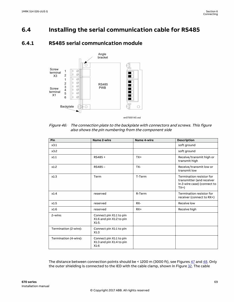
6.4 Installing the serial communication cable for RS485SEMOD176344-1 v1
6.4.1 RS485 serial communication moduleSEMOD176342-152 v6
RS485PWBScrew
terminalX1
Backplate
Screwterminal
X3
Anglebracket
12
456
3
12
en07000140.vsdIEC07000140 V1 EN-US
Figure 46: The connection plate to the backplate with connectors and screws. This figurealso shows the pin numbering from the component side
Pin Name 2-wire Name 4-wire Description
x3:1 soft ground
x3:2 soft ground
x1:1 RS485 + TX+ Receive/transmit high ortransmit high
x1:2 RS485 – TX- Receive/transmit low ortransmit low
x1:3 Term T-Term Termination resistor fortransmitter (and receiverin 2-wire case) (connect toTX+)
x1:4 reserved R-Term Termination resistor forreceiver (connect to RX+)
x1:5 reserved RX- Receive low
x1:6 reserved RX+ Receive high
2–wire: Connect pin X1:1 to pinX1:6 and pin X1:2 to pinX1:5.
Termination (2-wire): Connect pin X1:1 to pinX1:3
Termination (4-wire): Connect pin X1:1 to pinX1:3 and pin X1:4 to pinX1:6
The distance between connection points should be < 1200 m (3000 ft), see Figures 47 and 48. Onlythe outer shielding is connected to the IED with the cable clamp, shown in Figure 32. The cable
1MRK 514 026-UUS G Section 6Connecting
670 series 69Installation manual
© Copyright 2017 ABB. All rights reserved

shield shall be properly connected to the IED chassis with the cable clamp, where the maximumopen conductor length is 40 mm (1.57”) between clamp and terminals, see Figure 32. If doubleshielded cable is used, the inner cable shielding should be connected at the external equipmentend only. At the IED terminal end, the inner shield should be isolated. The inner and outershieldings are connected to the external equipment according to the installation instructions forthe actual equipment. Use insulating tape for the inner shield to prevent contact with the IEDchassis. Make sure that the IEDs are properly grounded with as short connections as possible fromthe ground screw, for example to an grounded frame.
The IED and the external equipment should preferably be connected to the same battery.
en07000141_ansi.vsd
Cc Cc1)
ExternalEquipment (PC)
PG 1) 3)
2)
PG
IED
X11 65432
IED
1 65432X1
PGPG
ANSI07000141 V1 EN-US
Figure 47: Communication cable installation, 2-wire
Where:
1 The inner shields shall be connected together (with an isolated terminal block) and only have oneconnection point in the whole system, preferably at the external equipment (PC).The outer shield shall be connected to the IED chassis in every cable end. Use the shield connection clampat all IEDs. The first IED will have only one cable end but all others require two.
2 Connect according to installation instructions for the actual equipment, observe the 120 ohmstermination.
3 Connect the screens according to the installation instructions for the actual equipment.
4 Shield connection clamp, see Figure 32.
Cc Communication cable
Section 6 1MRK 514 026-UUS GConnecting
70 670 seriesInstallation manual
© Copyright 2017 ABB. All rights reserved

en07000142_ansi.vsd
ExternalEquipment (PC)
PG 1) 3)
2)
IED
1 65432X1
PGPG
Cc
PG
IED
X11 65432
1)
1)
Cc
ANSI07000142 V1 EN-US
Figure 48: Communication cable installation, 4-wire
Where:
1 The inner shields shall be connected together (with an isolated terminal block) and only have oneconnection point in the whole system, preferably at the external equipment (PC).The outer shield shall be connected to the IED chassis in every cable end. Use the shield connection clampat all IEDs. The first IED will have only one cable end but all others require two.
2 Connect according to installation instructions for the actual equipment, observe the 120 ohmstermination.
3 Connect the screens according to the installation instructions for the actual equipment.
4 Shield connection clamp, see Figure 32.
Cc Communication cable
1MRK 514 026-UUS G Section 6Connecting
670 series 71Installation manual
© Copyright 2017 ABB. All rights reserved

en03000110.vsd
1
2
IEC03000110 V1 EN-US
Figure 49: Cable contact, Phoenix: MSTB2.5/6-ST-5.08 1757051
Where:
1 is cable
2 is screw
Conductor
Pair Shield
Pair separator
Jacket
Separator
Overall shield
Drain wire
en07000139.vsdIEC07000139 V1 EN-US
Figure 50: Cross section of communication cable
The EIA standard RS-485 specifies the RS485 network. An informative excerpt is given insection "Installing the serial communication cable for RS485 SPA/IEC".
6.4.2 Installing the serial communication cable for RS485 SPA/IECSEMOD176342-192 v3
Informative excerpt from EIA Standard RS-485 - Electrical Characteristics of Generators andReceivers for Balanced Digital Multipoint Systems
RS-485 Wire - Media dependent Physical layer
Section 6 1MRK 514 026-UUS GConnecting
72 670 seriesInstallation manual
© Copyright 2017 ABB. All rights reserved
1 Normative references
EIA Standard RS-485 - Electrical Characteristics of Generators and Receivers for BalancedDigital Multipoint Systems
2 Transmission method
RS-485 differential bipolar signaling
2.1 Differential signal levels
Two differential signal levels are defined:
A+ =line A positive with respect to line B
A- =line A negative with respect to line B
2.2 Galvanic isolation
The RS485 circuit shall be isolated from ground by:
Riso ≥ 10 MW
Ciso ≤ 10 pF
Three isolation options exist:
a) The entire node electronics can be galvanically isolated
b) The bus interface circuit can be isolated form the rest of node electronics byoptoisolators, transformer coupling or otherwise.
c) The RS485 chip can include built-in isolation
2.3 Bus excitation and signal conveyance
2.3.1 Requirements
a) The RS485 specification requires the Signal A and Signal B wires.
b) Each node also requires (5 V) Excitation of the RS485 termination network.
c) Vim - the common mode voltage between any pair of RS485 chips may not exceed10 V.
d) A physical ground connection between all RS485 circuits will reduce noise.
2.3.2 Bus segment termination network
The termination network below required at each end of each Bus Ph-segment.
Table continues on next page
1MRK 514 026-UUS G Section 6Connecting
670 series 73Installation manual
© Copyright 2017 ABB. All rights reserved

en03000112.vsd
ExV+
Signal B
Signal A
DGND
Ru = 390 ohm1/4 W, 2%
Rt = 220 ohm1/4 W, 2%
Rd = 390 ohm1/4 W, 2%
ExV is supplied by the Node at end of the Bus Segment
IEC03000112 V1 EN-US
Figure 51: RS-485 bus segment terminationExV is supplied by the Node at end of the Bus Segment
The specifications of the components are:
a) Ru + 5 V to Signal B = 390 W, 0.25 W ±2.5%
b) Rt Signal B to Signal A = 220 W, 0.25 W ±2.5%
c) Rd Signal A to GND = 390 W, 0.25 W ±2.5%
2.3.3 Bus power distribution
The end node in each Ph-segment applies 5 V bus excitation power to the Terminationnetwork via the Excitation pair (ExV+ and GND) used in the Type 3 Physical layerspecification.
6.4.3 Data on RS485 serial communication module cableSEMOD176342-280 v2
Type: Twisted-pair S-STP (Screened – Screened Twisted Pair)
Shield: Individual foil for each pair with overall copper braid
Length: Maximum 1200 m (3000 ft) from one system ground to the next system ground (includeslength from platform point to system ground on both sides)
Temp: According to application
Impedance: 120 W
Capacitance: Less than or equal to 42 pF/m
Example: Belden 9841,Alpha wire 6412, 6413
Section 6 1MRK 514 026-UUS GConnecting
74 670 seriesInstallation manual
© Copyright 2017 ABB. All rights reserved

6.5 Installing the GPS antennaSEMOD53073-1 v1
6.5.1 Antenna installationM12267-6 v3
The antenna is mounted on a console for mounting on a horizontal or vertical flat surface or on anantenna mast.
1
2
4
3
5
6
7
xx05000510.vsdIEC05000510 V1 EN-US
PosNO Description
1 GPS antenna
2 TNC connector
3 Console, 78x150 mm
4 Mounting holes 5.5 mm
5 Tab for securing of antenna cable
6 Vertical mounting position (on antenna mast etc.)
7 Horizontal mounting position
Mount the antenna and console clear of flat surfaces such as buildings walls, roofs and windows toavoid signal reflections. If necessary, protect the antenna from animals and birds which can affectsignal strength. Also protect the antenna against lightning.
Always position the antenna and its console so that a continuous clear line-of-sight visibility to alldirections is obtained, preferably more than 75%. A minimum of 50% clear line-of-sight visibility isrequired for un-interrupted operation.
1MRK 514 026-UUS G Section 6Connecting
670 series 75Installation manual
© Copyright 2017 ABB. All rights reserved

A
99001046.vsdIEC99001046 V1 EN-US
Figure 52: Antenna line-of-sight
6.5.2 Electrical installationM12267-34 v4
Use a 50 ohm coaxial cable with a male TNC connector on the antenna end and a male SMAconnector on the receiver end to connect the antenna to the IED. Choose cable type and length sothat the total attenuation is max. 26 dB at 1.6 GHz. A suitable antenna cable is supplied with theantenna.
The antenna has a female TNC connector to the antenna cable. For location of GPS time module(GTM), refer to section "Rear side connectors". Connection diagram for GTM is shown in figure 19.
Make sure that the antenna cable is not charged when connected to the antenna orto the receiver. Short-circuit the end of the antenna cable with some metal device,then connect to the antenna. When the antenna is connected to the cable, connectthe cable to the receiver. The IED must be switched off when the antenna cable isconnected.
6.5.3 Lightning protectionGUID-596EE08A-2D55-4EEA-B710-C11DC1E19C9B v1
The antenna should be mounted with adequate lightning protection, that is the antenna mastmust not rise above a neighboring lightning conductor.
Section 6 1MRK 514 026-UUS GConnecting
76 670 seriesInstallation manual
© Copyright 2017 ABB. All rights reserved

Section 7 Checking installation
7.1 Identifying hardware and software versionGUID-7527A986-F827-4104-B0E9-C62B1B0EF706 v1
The information of hardware and software versions of the IED are available on the label attachedon the case of the IED. There are also module labels that can be used to identify the differentmodules inside the IED (such as input-output cards and so on).
7.2 Checking mountingGUID-50578D7B-23D4-45B0-BB10-D3108EEF9B97 v2
Check that all fixing screws are tight and that all cables are connected.
7.3 Checking the power supplyM11725-2 v6
Do not insert anything else to the female connector but the corresponding maleconnector. Inserting anything else (such as a measurement probe) may damage thefemale connector and prevent a proper electrical contact between the printedcircuit board and the external wiring connected to the screw terminal block.
Check that the auxiliary supply voltage remains within the permissible input voltage range underall operating conditions. Check that the polarity is correct before energizing the IED.
7.4 Energizing the IEDGUID-E40DE80C-8DA4-4E17-876C-4CC3CE706347 v4
Before connecting the auxiliary power, check that the terminal strip is wired and placed correctly.Remove the protective film from the top side of the unit.
During IED start-up, you can observe the following sequence:
1. The Green Normal LED starts to flash.2. The LCD lights up and starting... is displayed.3. The main menu is displayed. A final steady green Normal LED indicates a successful start-up
of the device.
If the self supervision of the IED detects a diagnostic error during the start-up process, the greenNormal LED flashes. Further information on the error may be visible on the local HMI under Mainmenu/Diagnostics/IED status/General. Note down the displayed information as reference whencontacting ABB technical support.
1MRK 514 026-UUS G Section 7Checking installation
670 series 77Installation manual
© Copyright 2017 ABB. All rights reserved

78

Section 8 Removing, repairing and exchanging
8.1 Product lifecycleGUID-D1A48469-E2DB-4E39-8431-1686F13FFC4D v8
At some point of the product lifecycle, the IED will be upgraded to a next generation unit. Whenselecting the original product, already consider the upgrading and extension possibilities that thespecific product offers for its whole lifecycle.
8.2 Checking IED informationGUID-2CAE273B-B384-438A-B21C-C0BC86E203A1 v3
The IED information includes detailed information about the device, such as version and serialnumber. To find the information navigate through the LHMI menus as indicated below:
1. Select Main Menu/Diagnostics/IED status.2. Select a submenu with and .3. Enter the selected submenu with .4. Browse the information with and .
The Product identifiers submenu contains product related information including product type,serial number, order number, production date and SW version.
The Installed HW submenu contains information about the HW modules.
8.3 Removing the IEDGUID-6F99E661-D319-4782-97E9-3A864B1E972D v2
Before removing the IED, make sure that auxiliary power is turned off and all wiring isdisconnected.
For upgrade purposes the IED does not need to be removed. Before removing theIED check with your local ABB office if the IED can be upgraded.
8.4 Sending the IED for repairAMU0600445 v4
In case of product problems, contact the nearest ABB office or representative for consultation andinstructions.
8.5 Exchanging the IEDGUID-1EB39784-696C-4B2E-B560-4115F721DCAB v9
To exchange the IED with another identical unit, remove the IED and install the new one. Contactyour local ABB for information about exchangeable units.
1MRK 514 026-UUS G Section 8Removing, repairing and exchanging
670 series 79Installation manual
© Copyright 2017 ABB. All rights reserved

80

Section 9 Technical data
9.1 DimensionsIP11490-1 v3
9.1.1 Case without protective coverSEMOD53195-1 v2
M2152-3 v8
IEC08000164-4-en.vsdx
IEC08000164 V4 EN-US
Figure 53: Case without protective cover
1MRK 514 026-UUS G Section 9Technical data
670 series 81Installation manual
© Copyright 2017 ABB. All rights reserved

IEC08000166‐3‐en.vsdx
IEC08000166 V3 EN-US
Figure 54: Case without protective cover with 19” rack mounting kitM2152-11 v5
Case size(inches)
A B C D E F G H I
6U, 1/2 x 19” 10.5 8.81 8.03 9.83 8.10 7.50 18.36 7.44 19.00
6U, 3/4 x 19” 10.5 13.23 8.03 9.83 12.51 7.50 18.36 7.44 19.00
6U, 1/1 x 19” 10.5 17.64 8.03 9.83 16.93 7.50 18.36 7.44 19.00
The G and I dimensions are defined by the 19” rack mounting kit
Section 9 1MRK 514 026-UUS GTechnical data
82 670 seriesInstallation manual
© Copyright 2017 ABB. All rights reserved

9.1.2 Case with protective coverSEMOD53199-1 v2
M11985-110 v7
IEC08000163‐3‐en.vsdx
IEC08000163 V3 EN-US
Figure 55: Case with protective cover
1MRK 514 026-UUS G Section 9Technical data
670 series 83Installation manual
© Copyright 2017 ABB. All rights reserved

IEC08000165‐3‐en.vsdx
IEC08000165 V3 EN-US
Figure 56: Case with protective cover and 19” rack mounting kit
Section 9 1MRK 514 026-UUS GTechnical data
84 670 seriesInstallation manual
© Copyright 2017 ABB. All rights reserved

IEC05000503-3-en.vsdx
IEC05000503 V3 EN-US
Figure 57: Protective cover case with detailsM11985-120 v6
Case size(inches)
A B C D E F G H I
6U, 1/2 x 19” 10.47 8.81 9.74 10.04 8.10 7.50 18.36 9.15 19.00
6U, 3/4 x 19” 10.47 13.23 9.74 10.04 12.52 7.50 18.36 9.15 19.00
6U, 1/1 x 19” 10.47 17.65 9.74 10.04 16.86 7.50 18.36 9.15 19.00
The G and Idimensions are defined by the 19” rack mounting kit.
1MRK 514 026-UUS G Section 9Technical data
670 series 85Installation manual
© Copyright 2017 ABB. All rights reserved

9.1.3 Flush mounting dimensionsM11571-3 v6
CA
IEC04000465-3-en.vsd
B
ED
IEC04000465 V3 EN-US
Figure 58: Flush mounting
Case sizeTolerance
Cut-out dimensions (inches)
A+/0.04
B+/0.04
C D
6U, 1/2 x 19” 8.27 10.01 0.16–0.39 0.53
6U, 3/4 x 19” 12.69 10.01 0.16–0.39 0.53
6U, 1/1 x 19” 17.11 10.01 0.16–0.39 0.53
E = 7.52” without rear protection cover, 9.12” with rear protection cover
Section 9 1MRK 514 026-UUS GTechnical data
86 670 seriesInstallation manual
© Copyright 2017 ABB. All rights reserved

9.1.4 Side-by-side flush mounting dimensionsM11984-3 v6
IEC06000182-2-en.vsdIEC06000182 V2 EN-US
Figure 59: A 1/2 x 19” size IED side-by-side with RHGS6
xx05000505.vsd
B
A
C
GD
E
F
IEC05000505 V1 EN-US
Figure 60: Panel-cut out dimensions for side-by-side flush mounting
Case size(inches)Tolerance
A±0.04
B±0.04
C±0.04
D±0.04
E±0.04
F±0.04
G±0.04
6U, 1/2 x 19” 8.42 10.21 9.46 7.50 1.35 0.52 0.25 diam
6U, 3/4 x 19” 12.85 10.21 13.89 7.50 1.35 0.52 0.25 diam
6U, 1/1 x 19” 17.27 10.21 18.31 7.50 1.35 0.52 0.25 diam
1MRK 514 026-UUS G Section 9Technical data
670 series 87Installation manual
© Copyright 2017 ABB. All rights reserved

9.1.5 Wall mounting dimensionsM11569-3 v5
IEC04000471-2-en.vsdIEC04000471 V2 EN-US
Figure 61: Wall mounting
Case size (inches) A B C D E
6U, 1/2 x 19” 10.50 10.52 10.74 15.36 9.57
6U, 3/4 x 19” 15.92 14.94 10.74 15.36 9.57
6U, 1/1 x 19” 20.31 19.33 10.74 15.36 9.57
Section 9 1MRK 514 026-UUS GTechnical data
88 670 seriesInstallation manual
© Copyright 2017 ABB. All rights reserved

Section 10 GlossaryM14893-1 v18
AC Alternating current
ACC Actual channel
ACT Application configuration tool within PCM600
A/D converter Analog-to-digital converter
ADBS Amplitude deadband supervision
ADM Analog digital conversion module, with time synchronization
AI Analog input
ANSI American National Standards Institute
AR Autoreclosing
ASCT Auxiliary summation current transformer
ASD Adaptive signal detection
ASDU Application service data unit
AWG American Wire Gauge standard
BBP Busbar protection
BFOC/2,5 Bayonet fiber optic connector
BFP Breaker failure protection
BI Binary input
BIM Binary input module
BOM Binary output module
BOS Binary outputs status
BR External bistable relay
BS British Standards
BSR Binary signal transfer function, receiver blocks
BST Binary signal transfer function, transmit blocks
C37.94 IEEE/ANSI protocol used when sending binary signals between IEDs
CAN Controller Area Network. ISO standard (ISO 11898) for serialcommunication
CB Circuit breaker
CBM Combined backplane module
CCITT Consultative Committee for International Telegraph and Telephony. AUnited Nations-sponsored standards body within the InternationalTelecommunications Union.
CCM CAN carrier module
CCVT Capacitive Coupled Voltage Transformer
1MRK 514 026-UUS G Section 10Glossary
670 series 89Installation manual
© Copyright 2017 ABB. All rights reserved

Class C Protection Current Transformer class as per IEEE/ ANSI
CMPPS Combined megapulses per second
CMT Communication Management tool in PCM600
CO cycle Close-open cycle
Codirectional Way of transmitting G.703 over a balanced line. Involves two twisted pairsmaking it possible to transmit information in both directions
COM Command
COMTRADE Standard Common Format for Transient Data Exchange format forDisturbance recorder according to IEEE/ANSI C37.111, 1999 / IEC 60255-24
Contra-directional Way of transmitting G.703 over a balanced line. Involves four twisted pairs,two of which are used for transmitting data in both directions and two fortransmitting clock signals
COT Cause of transmission
CPU Central processing unit
CR Carrier receive
CRC Cyclic redundancy check
CROB Control relay output block
CS Carrier send
CT Current transformer
CU Communication unit
CVT or CCVT Capacitive voltage transformer
DAR Delayed autoreclosing
DARPA Defense Advanced Research Projects Agency (The US developer of theTCP/IP protocol etc.)
DBDL Dead bus dead line
DBLL Dead bus live line
DC Direct current
DFC Data flow control
DFT Discrete Fourier transform
DHCP Dynamic Host Configuration Protocol
DIP-switch Small switch mounted on a printed circuit board
DI Digital input
DLLB Dead line live bus
DNP Distributed Network Protocol as per IEEE Std 1815-2012
DR Disturbance recorder
DRAM Dynamic random access memory
DRH Disturbance report handler
DSP Digital signal processor
DTT Direct transfer trip scheme
Section 10 1MRK 514 026-UUS GGlossary
90 670 seriesInstallation manual
© Copyright 2017 ABB. All rights reserved

ECT Ethernet configuration tool
EHV network Extra high voltage network
EIA Electronic Industries Association
EMC Electromagnetic compatibility
EMF Electromotive force
EMI Electromagnetic interference
EnFP End fault protection
EPA Enhanced performance architecture
ESD Electrostatic discharge
F-SMA Type of optical fiber connector
FAN Fault number
FCB Flow control bit; Frame count bit
FOX 20 Modular 20 channel telecommunication system for speech, data andprotection signals
FOX 512/515 Access multiplexer
FOX 6Plus Compact time-division multiplexer for the transmission of up to sevenduplex channels of digital data over optical fibers
FPN Flexible product naming
FTP File Transfer Protocol
FUN Function type
G.703 Electrical and functional description for digital lines used by localtelephone companies. Can be transported over balanced and unbalancedlines
GCM Communication interface module with carrier of GPS receiver module
GDE Graphical display editor within PCM600
GI General interrogation command
GIS Gas-insulated switchgear
GOOSE Generic object-oriented substation event
GPS Global positioning system
GSAL Generic security application
GSE Generic substation event
HDLC protocol High-level data link control, protocol based on the HDLC standard
HFBR connector type Plastic fiber connector
HLV circuit Hazardous Live Voltage according to IEC60255-27
HMI Human-machine interface
HSAR High speed autoreclosing
HSR High-availability Seamless Redundancy
HV High-voltage
HVDC High-voltage direct current
1MRK 514 026-UUS G Section 10Glossary
670 series 91Installation manual
© Copyright 2017 ABB. All rights reserved

ICT Installation and Commissioning Tool for injection based protection inREG670
IDBS Integrating deadband supervision
IEC International Electrical Committee
IEC 60044-6 IEC Standard, Instrument transformers – Part 6: Requirements forprotective current transformers for transient performance
IEC 60870-5-103 Communication standard for protection equipment. A serial master/slaveprotocol for point-to-point communication
IEC 61850 Substation automation communication standard
IEC 61850–8–1 Communication protocol standard
IEEE Institute of Electrical and Electronics Engineers
IEEE 802.12 A network technology standard that provides 100 Mbits/s on twisted-pairor optical fiber cable
IEEE P1386.1 PCI Mezzanine Card (PMC) standard for local bus modules. References theCMC (IEEE P1386, also known as Common Mezzanine Card) standard forthe mechanics and the PCI specifications from the PCI SIG (Special InterestGroup) for the electrical EMF (Electromotive force).
IEEE 1686 Standard for Substation Intelligent Electronic Devices (IEDs) Cyber SecurityCapabilities
IED Intelligent electronic device
IET600 Integrated engineering tool
I-GIS Intelligent gas-insulated switchgear
IOM Binary input/output module
Instance When several occurrences of the same function are available in the IED,they are referred to as instances of that function. One instance of afunction is identical to another of the same kind but has a differentnumber in the IED user interfaces. The word "instance" is sometimesdefined as an item of information that is representative of a type. In thesame way an instance of a function in the IED is representative of a type offunction.
IP 1. Internet protocol. The network layer for the TCP/IP protocol suite widelyused on Ethernet networks. IP is a connectionless, best-effort packet-switching protocol. It provides packet routing, fragmentation andreassembly through the data link layer.2. Ingression protection, according to IEC 60529
IP 20 Ingression protection, according to IEC 60529, levelIP20- Protected against solid foreign objects of 12.5mm diameter andgreater.
IP 40 Ingression protection, according to IEC 60529, level IP40-Protected againstsolid foreign objects of 1mm diameter and greater.
IP 54 Ingression protection, according to IEC 60529, levelIP54-Dust-protected, protected against splashing water.
IRF Internal failure signal
IRIG-B: InterRange Instrumentation Group Time code format B, standard 200
Section 10 1MRK 514 026-UUS GGlossary
92 670 seriesInstallation manual
© Copyright 2017 ABB. All rights reserved

ITU International Telecommunications Union
LAN Local area network
LIB 520 High-voltage software module
LCD Liquid crystal display
LDCM Line data communication module
LDD Local detection device
LED Light-emitting diode
LNT LON network tool
LON Local operating network
MCB Miniature circuit breaker
MCM Mezzanine carrier module
MIM Milli-ampere module
MPM Main processing module
MVAL Value of measurement
MVB Multifunction vehicle bus. Standardized serial bus originally developed foruse in trains.
NCC National Control Centre
NOF Number of grid faults
NUM Numerical module
OCO cycle Open-close-open cycle
OCP Overcurrent protection
OEM Optical Ethernet module
OLTC On-load tap changer
OTEV Disturbance data recording initiated by other event than start/pick-up
OV Overvoltage
Overreach A term used to describe how the relay behaves during a fault condition. Forexample, a distance relay is overreaching when the impedance presentedto it is smaller than the apparent impedance to the fault applied to thebalance point, that is, the set reach. The relay “sees” the fault but perhapsit should not have seen it.
PCI Peripheral component interconnect, a local data bus
PCM Pulse code modulation
PCM600 Protection and control IED manager
PC-MIP Mezzanine card standard
PELV circuit Protected Extra-Low Voltage circuit type according to IEC60255-27
PMC PCI Mezzanine card
POR Permissive overreach
POTT Permissive overreach transfer trip
1MRK 514 026-UUS G Section 10Glossary
670 series 93Installation manual
© Copyright 2017 ABB. All rights reserved

Process bus Bus or LAN used at the process level, that is, in near proximity to themeasured and/or controlled components
PRP Parallel redundancy protocol
PSM Power supply module
PST Parameter setting tool within PCM600
PTP Precision time protocol
PT ratio Potential transformer or voltage transformer ratio
PUTT Permissive underreach transfer trip
RASC Synchrocheck relay, COMBIFLEX
RCA Relay characteristic angle
RISC Reduced instruction set computer
RMS value Root mean square value
RS422 A balanced serial interface for the transmission of digital data in point-to-point connections
RS485 Serial link according to EIA standard RS485
RTC Real-time clock
RTU Remote terminal unit
SA Substation Automation
SBO Select-before-operate
SC Switch or push button to close
SCL Short circuit location
SCS Station control system
SCADA Supervision, control and data acquisition
SCT System configuration tool according to standard IEC 61850
SDU Service data unit
SELV circuit Safety Extra-Low Voltage circuit type according to IEC60255-27
SFP Small form-factor pluggable (abbreviation)Optical Ethernet port (explanation)
SLM Serial communication module.
SMA connector Subminiature version A, A threaded connector with constant impedance.
SMT Signal matrix tool within PCM600
SMS Station monitoring system
SNTP Simple network time protocol – is used to synchronize computer clocks onlocal area networks. This reduces the requirement to have accuratehardware clocks in every embedded system in a network. Each embeddednode can instead synchronize with a remote clock, providing the requiredaccuracy.
SOF Status of fault
Section 10 1MRK 514 026-UUS GGlossary
94 670 seriesInstallation manual
© Copyright 2017 ABB. All rights reserved

SPA Strömberg Protection Acquisition (SPA), a serial master/slave protocol forpoint-to-point and ring communication.
SRY Switch for CB ready condition
ST Switch or push button to trip
Starpoint Neutral/Wye point of transformer or generator
SVC Static VAr compensation
TC Trip coil
TCS Trip circuit supervision
TCP Transmission control protocol. The most common transport layer protocolused on Ethernet and the Internet.
TCP/IP Transmission control protocol over Internet Protocol. The de factostandard Ethernet protocols incorporated into 4.2BSD Unix. TCP/IP wasdeveloped by DARPA for Internet working and encompasses both networklayer and transport layer protocols. While TCP and IP specify two protocolsat specific protocol layers, TCP/IP is often used to refer to the entire USDepartment of Defense protocol suite based upon these, including Telnet,FTP, UDP and RDP.
TEF Time delayed gound-fault protection function
TLS Transport Layer Security
TM Transmit (disturbance data)
TNC connector Threaded Neill-Concelman, a threaded constant impedance version of aBNC connector
TP Trip (recorded fault)
TPZ, TPY, TPX, TPS Current transformer class according to IEC
TRM Transformer Module. This module transforms currents and voltages takenfrom the process into levels suitable for further signal processing.
TYP Type identification
UMT User management tool
Underreach A term used to describe how the relay behaves during a fault condition. Forexample, a distance relay is underreaching when the impedance presentedto it is greater than the apparent impedance to the fault applied to thebalance point, that is, the set reach. The relay does not “see” the fault butperhaps it should have seen it. See also Overreach.
UTC Coordinated Universal Time. A coordinated time scale, maintained by theBureau International des Poids et Mesures (BIPM), which forms the basis ofa coordinated dissemination of standard frequencies and time signals.UTC is derived from International Atomic Time (TAI) by the addition of awhole number of "leap seconds" to synchronize it with Universal Time 1(UT1), thus allowing for the eccentricity of the Earth's orbit, the rotationalaxis tilt (23.5 degrees), but still showing the Earth's irregular rotation, onwhich UT1 is based. The Coordinated Universal Time is expressed using a24-hour clock, and uses the Gregorian calendar. It is used for aeroplane andship navigation, where it is also sometimes known by the military name,"Zulu time." "Zulu" in the phonetic alphabet stands for "Z", which stands forlongitude zero.
UV Undervoltage
1MRK 514 026-UUS G Section 10Glossary
670 series 95Installation manual
© Copyright 2017 ABB. All rights reserved

WEI Weak end infeed logic
VT Voltage transformer
X.21 A digital signalling interface primarily used for telecom equipment
3IO Three times zero-sequence current.Often referred to as the residual or theground-fault current
3VO Three times the zero sequence voltage. Often referred to as the residualvoltage or the neutral point voltage
Section 10 1MRK 514 026-UUS GGlossary
96 670 seriesInstallation manual
© Copyright 2017 ABB. All rights reserved

97

ABB ABGrid Automation ProductsSE-721 59 Västerås, SwedenPhone +46 (0) 21 32 50 00
www.abb.com/protection-control
© Copyright 2017 ABB.All rights reserved.
Scan this QR code to visit our website1M
RK
514
026
-UU
S